WO2015050355A1 - 최대 변형률 측정을 위한 fbg 센서, 제조방법 및 사용방법 - Google Patents
최대 변형률 측정을 위한 fbg 센서, 제조방법 및 사용방법 Download PDFInfo
- Publication number
- WO2015050355A1 WO2015050355A1 PCT/KR2014/009159 KR2014009159W WO2015050355A1 WO 2015050355 A1 WO2015050355 A1 WO 2015050355A1 KR 2014009159 W KR2014009159 W KR 2014009159W WO 2015050355 A1 WO2015050355 A1 WO 2015050355A1
- Authority
- WO
- WIPO (PCT)
- Prior art keywords
- fbg sensor
- maximum strain
- optical fiber
- metal foil
- strain
- Prior art date
- Legal status (The legal status is an assumption and is not a legal conclusion. Google has not performed a legal analysis and makes no representation as to the accuracy of the status listed.)
- Ceased
Links
Images


Classifications
-
- G—PHYSICS
- G01—MEASURING; TESTING
- G01L—MEASURING FORCE, STRESS, TORQUE, WORK, MECHANICAL POWER, MECHANICAL EFFICIENCY, OR FLUID PRESSURE
- G01L1/00—Measuring force or stress, in general
- G01L1/24—Measuring force or stress, in general by measuring variations of optical properties of material when it is stressed, e.g. by photoelastic stress analysis using infrared, visible light, ultraviolet
- G01L1/242—Measuring force or stress, in general by measuring variations of optical properties of material when it is stressed, e.g. by photoelastic stress analysis using infrared, visible light, ultraviolet the material being an optical fibre
- G01L1/246—Measuring force or stress, in general by measuring variations of optical properties of material when it is stressed, e.g. by photoelastic stress analysis using infrared, visible light, ultraviolet the material being an optical fibre using integrated gratings, e.g. Bragg gratings
-
- G—PHYSICS
- G01—MEASURING; TESTING
- G01B—MEASURING LENGTH, THICKNESS OR SIMILAR LINEAR DIMENSIONS; MEASURING ANGLES; MEASURING AREAS; MEASURING IRREGULARITIES OF SURFACES OR CONTOURS
- G01B1/00—Measuring instruments characterised by the selection of material therefor
-
- G—PHYSICS
- G01—MEASURING; TESTING
- G01B—MEASURING LENGTH, THICKNESS OR SIMILAR LINEAR DIMENSIONS; MEASURING ANGLES; MEASURING AREAS; MEASURING IRREGULARITIES OF SURFACES OR CONTOURS
- G01B11/00—Measuring arrangements characterised by the use of optical techniques
- G01B11/16—Measuring arrangements characterised by the use of optical techniques for measuring the deformation in a solid, e.g. optical strain gauge
-
- G—PHYSICS
- G01—MEASURING; TESTING
- G01B—MEASURING LENGTH, THICKNESS OR SIMILAR LINEAR DIMENSIONS; MEASURING ANGLES; MEASURING AREAS; MEASURING IRREGULARITIES OF SURFACES OR CONTOURS
- G01B11/00—Measuring arrangements characterised by the use of optical techniques
- G01B11/16—Measuring arrangements characterised by the use of optical techniques for measuring the deformation in a solid, e.g. optical strain gauge
- G01B11/165—Measuring arrangements characterised by the use of optical techniques for measuring the deformation in a solid, e.g. optical strain gauge by means of a grating deformed by the object
-
- G—PHYSICS
- G01—MEASURING; TESTING
- G01B—MEASURING LENGTH, THICKNESS OR SIMILAR LINEAR DIMENSIONS; MEASURING ANGLES; MEASURING AREAS; MEASURING IRREGULARITIES OF SURFACES OR CONTOURS
- G01B11/00—Measuring arrangements characterised by the use of optical techniques
- G01B11/16—Measuring arrangements characterised by the use of optical techniques for measuring the deformation in a solid, e.g. optical strain gauge
- G01B11/18—Measuring arrangements characterised by the use of optical techniques for measuring the deformation in a solid, e.g. optical strain gauge using photoelastic elements
-
- G—PHYSICS
- G01—MEASURING; TESTING
- G01D—MEASURING NOT SPECIALLY ADAPTED FOR A SPECIFIC VARIABLE; ARRANGEMENTS FOR MEASURING TWO OR MORE VARIABLES NOT COVERED IN A SINGLE OTHER SUBCLASS; TARIFF METERING APPARATUS; MEASURING OR TESTING NOT OTHERWISE PROVIDED FOR
- G01D5/00—Mechanical means for transferring the output of a sensing member; Means for converting the output of a sensing member to another variable where the form or nature of the sensing member does not constrain the means for converting; Transducers not specially adapted for a specific variable
- G01D5/26—Mechanical means for transferring the output of a sensing member; Means for converting the output of a sensing member to another variable where the form or nature of the sensing member does not constrain the means for converting; Transducers not specially adapted for a specific variable characterised by optical transfer means, i.e. using infrared, visible, or ultraviolet light
- G01D5/32—Mechanical means for transferring the output of a sensing member; Means for converting the output of a sensing member to another variable where the form or nature of the sensing member does not constrain the means for converting; Transducers not specially adapted for a specific variable characterised by optical transfer means, i.e. using infrared, visible, or ultraviolet light with attenuation or whole or partial obturation of beams of light
- G01D5/34—Mechanical means for transferring the output of a sensing member; Means for converting the output of a sensing member to another variable where the form or nature of the sensing member does not constrain the means for converting; Transducers not specially adapted for a specific variable characterised by optical transfer means, i.e. using infrared, visible, or ultraviolet light with attenuation or whole or partial obturation of beams of light the beams of light being detected by photocells
- G01D5/353—Mechanical means for transferring the output of a sensing member; Means for converting the output of a sensing member to another variable where the form or nature of the sensing member does not constrain the means for converting; Transducers not specially adapted for a specific variable characterised by optical transfer means, i.e. using infrared, visible, or ultraviolet light with attenuation or whole or partial obturation of beams of light the beams of light being detected by photocells influencing the transmission properties of an optical fibre
-
- G—PHYSICS
- G01—MEASURING; TESTING
- G01D—MEASURING NOT SPECIALLY ADAPTED FOR A SPECIFIC VARIABLE; ARRANGEMENTS FOR MEASURING TWO OR MORE VARIABLES NOT COVERED IN A SINGLE OTHER SUBCLASS; TARIFF METERING APPARATUS; MEASURING OR TESTING NOT OTHERWISE PROVIDED FOR
- G01D5/00—Mechanical means for transferring the output of a sensing member; Means for converting the output of a sensing member to another variable where the form or nature of the sensing member does not constrain the means for converting; Transducers not specially adapted for a specific variable
- G01D5/26—Mechanical means for transferring the output of a sensing member; Means for converting the output of a sensing member to another variable where the form or nature of the sensing member does not constrain the means for converting; Transducers not specially adapted for a specific variable characterised by optical transfer means, i.e. using infrared, visible, or ultraviolet light
- G01D5/32—Mechanical means for transferring the output of a sensing member; Means for converting the output of a sensing member to another variable where the form or nature of the sensing member does not constrain the means for converting; Transducers not specially adapted for a specific variable characterised by optical transfer means, i.e. using infrared, visible, or ultraviolet light with attenuation or whole or partial obturation of beams of light
- G01D5/34—Mechanical means for transferring the output of a sensing member; Means for converting the output of a sensing member to another variable where the form or nature of the sensing member does not constrain the means for converting; Transducers not specially adapted for a specific variable characterised by optical transfer means, i.e. using infrared, visible, or ultraviolet light with attenuation or whole or partial obturation of beams of light the beams of light being detected by photocells
- G01D5/353—Mechanical means for transferring the output of a sensing member; Means for converting the output of a sensing member to another variable where the form or nature of the sensing member does not constrain the means for converting; Transducers not specially adapted for a specific variable characterised by optical transfer means, i.e. using infrared, visible, or ultraviolet light with attenuation or whole or partial obturation of beams of light the beams of light being detected by photocells influencing the transmission properties of an optical fibre
- G01D5/35306—Mechanical means for transferring the output of a sensing member; Means for converting the output of a sensing member to another variable where the form or nature of the sensing member does not constrain the means for converting; Transducers not specially adapted for a specific variable characterised by optical transfer means, i.e. using infrared, visible, or ultraviolet light with attenuation or whole or partial obturation of beams of light the beams of light being detected by photocells influencing the transmission properties of an optical fibre using an interferometer arrangement
- G01D5/35309—Mechanical means for transferring the output of a sensing member; Means for converting the output of a sensing member to another variable where the form or nature of the sensing member does not constrain the means for converting; Transducers not specially adapted for a specific variable characterised by optical transfer means, i.e. using infrared, visible, or ultraviolet light with attenuation or whole or partial obturation of beams of light the beams of light being detected by photocells influencing the transmission properties of an optical fibre using an interferometer arrangement using multiple waves interferometer
- G01D5/35316—Mechanical means for transferring the output of a sensing member; Means for converting the output of a sensing member to another variable where the form or nature of the sensing member does not constrain the means for converting; Transducers not specially adapted for a specific variable characterised by optical transfer means, i.e. using infrared, visible, or ultraviolet light with attenuation or whole or partial obturation of beams of light the beams of light being detected by photocells influencing the transmission properties of an optical fibre using an interferometer arrangement using multiple waves interferometer using a Bragg gratings
-
- G—PHYSICS
- G01—MEASURING; TESTING
- G01D—MEASURING NOT SPECIALLY ADAPTED FOR A SPECIFIC VARIABLE; ARRANGEMENTS FOR MEASURING TWO OR MORE VARIABLES NOT COVERED IN A SINGLE OTHER SUBCLASS; TARIFF METERING APPARATUS; MEASURING OR TESTING NOT OTHERWISE PROVIDED FOR
- G01D5/00—Mechanical means for transferring the output of a sensing member; Means for converting the output of a sensing member to another variable where the form or nature of the sensing member does not constrain the means for converting; Transducers not specially adapted for a specific variable
- G01D5/26—Mechanical means for transferring the output of a sensing member; Means for converting the output of a sensing member to another variable where the form or nature of the sensing member does not constrain the means for converting; Transducers not specially adapted for a specific variable characterised by optical transfer means, i.e. using infrared, visible, or ultraviolet light
- G01D5/32—Mechanical means for transferring the output of a sensing member; Means for converting the output of a sensing member to another variable where the form or nature of the sensing member does not constrain the means for converting; Transducers not specially adapted for a specific variable characterised by optical transfer means, i.e. using infrared, visible, or ultraviolet light with attenuation or whole or partial obturation of beams of light
- G01D5/34—Mechanical means for transferring the output of a sensing member; Means for converting the output of a sensing member to another variable where the form or nature of the sensing member does not constrain the means for converting; Transducers not specially adapted for a specific variable characterised by optical transfer means, i.e. using infrared, visible, or ultraviolet light with attenuation or whole or partial obturation of beams of light the beams of light being detected by photocells
- G01D5/353—Mechanical means for transferring the output of a sensing member; Means for converting the output of a sensing member to another variable where the form or nature of the sensing member does not constrain the means for converting; Transducers not specially adapted for a specific variable characterised by optical transfer means, i.e. using infrared, visible, or ultraviolet light with attenuation or whole or partial obturation of beams of light the beams of light being detected by photocells influencing the transmission properties of an optical fibre
- G01D5/3537—Optical fibre sensor using a particular arrangement of the optical fibre itself
-
- G—PHYSICS
- G01—MEASURING; TESTING
- G01K—MEASURING TEMPERATURE; MEASURING QUANTITY OF HEAT; THERMALLY-SENSITIVE ELEMENTS NOT OTHERWISE PROVIDED FOR
- G01K11/00—Measuring temperature based upon physical or chemical changes not covered by groups G01K3/00, G01K5/00, G01K7/00 or G01K9/00
- G01K11/32—Measuring temperature based upon physical or chemical changes not covered by groups G01K3/00, G01K5/00, G01K7/00 or G01K9/00 using changes in transmittance, scattering or luminescence in optical fibres
- G01K11/3206—Measuring temperature based upon physical or chemical changes not covered by groups G01K3/00, G01K5/00, G01K7/00 or G01K9/00 using changes in transmittance, scattering or luminescence in optical fibres at discrete locations in the fibre, e.g. using Bragg scattering
-
- G—PHYSICS
- G01—MEASURING; TESTING
- G01L—MEASURING FORCE, STRESS, TORQUE, WORK, MECHANICAL POWER, MECHANICAL EFFICIENCY, OR FLUID PRESSURE
- G01L1/00—Measuring force or stress, in general
- G01L1/24—Measuring force or stress, in general by measuring variations of optical properties of material when it is stressed, e.g. by photoelastic stress analysis using infrared, visible light, ultraviolet
- G01L1/242—Measuring force or stress, in general by measuring variations of optical properties of material when it is stressed, e.g. by photoelastic stress analysis using infrared, visible light, ultraviolet the material being an optical fibre
-
- G—PHYSICS
- G01—MEASURING; TESTING
- G01M—TESTING STATIC OR DYNAMIC BALANCE OF MACHINES OR STRUCTURES; TESTING OF STRUCTURES OR APPARATUS, NOT OTHERWISE PROVIDED FOR
- G01M11/00—Testing of optical apparatus; Testing structures by optical methods not otherwise provided for
- G01M11/08—Testing mechanical properties
- G01M11/083—Testing mechanical properties by using an optical fiber in contact with the device under test [DUT]
- G01M11/085—Testing mechanical properties by using an optical fiber in contact with the device under test [DUT] the optical fiber being on or near the surface of the DUT
-
- G—PHYSICS
- G01—MEASURING; TESTING
- G01M—TESTING STATIC OR DYNAMIC BALANCE OF MACHINES OR STRUCTURES; TESTING OF STRUCTURES OR APPARATUS, NOT OTHERWISE PROVIDED FOR
- G01M5/00—Investigating the elasticity of structures, e.g. deflection of bridges or air-craft wings
- G01M5/0033—Investigating the elasticity of structures, e.g. deflection of bridges or air-craft wings by determining damage, crack or wear
-
- G—PHYSICS
- G01—MEASURING; TESTING
- G01N—INVESTIGATING OR ANALYSING MATERIALS BY DETERMINING THEIR CHEMICAL OR PHYSICAL PROPERTIES
- G01N21/00—Investigating or analysing materials by the use of optical means, i.e. using sub-millimetre waves, infrared, visible or ultraviolet light
- G01N21/17—Systems in which incident light is modified in accordance with the properties of the material investigated
- G01N21/41—Refractivity; Phase-affecting properties, e.g. optical path length
- G01N21/412—Index profiling of optical fibres
-
- G—PHYSICS
- G01—MEASURING; TESTING
- G01N—INVESTIGATING OR ANALYSING MATERIALS BY DETERMINING THEIR CHEMICAL OR PHYSICAL PROPERTIES
- G01N21/00—Investigating or analysing materials by the use of optical means, i.e. using sub-millimetre waves, infrared, visible or ultraviolet light
- G01N21/84—Systems specially adapted for particular applications
- G01N21/88—Investigating the presence of flaws or contamination
- G01N21/8806—Specially adapted optical and illumination features
Definitions
- the present invention relates to an FBG sensor, and more particularly, to a FBG sensor, a method for manufacturing the sensor, and a method for using the sensor that can measure the maximum strain of the measurement object.
- FBG Fiber Bragg Grating
- the FBG sensor selectively irradiates the glass optical fiber with ultraviolet rays to give a pattern in which the refractive index periodically changes in the longitudinal direction of the optical fiber.
- This FBG sensor can be made as a filter inside the optical fiber, so the insertion loss is small. In addition, for mass production, the manufacturing cost is very small and the bandwidth of the filter can be made very small.
- FBG sensor Other features of the FBG sensor are less likely to deteriorate due to corrosion, which makes it suitable for embedded measurement (durability), and there is no abnormality caused by moisture due to the use of optical signals (reliability). Since it is transmitted to the measuring instrument by the optical signal, it is not affected by the electric field of the measuring place (especially in high voltage power environment (noise). The signal has extremely low transmission loss and can be measured in the range of several kilometers, so it can be used for long tunnels and large structures (applicability) .It can be used from cryogenic (-270 degrees) to extremely high temperature (hundreds of degrees). It can be used in cryogenic and high temperature (temperature), especially FBG fiber optic sensor can measure the stress in concrete like conventional electric measuring instruments and can maintain the measuring function for more than one year even in harsh environment. Very high.
- Such FBG sensors include time division multiplexing (TDM) using time difference and wave division multiplexing (WDM) using difference of waveforms.
- TDM time division multiplexing
- WDM wave division multiplexing
- wavelength division multiplexing is a method of identifying FBG above the reflection wavelength inherent in each FBG and enables long-range measurement.
- FBG sensors have been developed in the field of Structural Health Monitoring (SHM), such as strain measurement, crack diagnosis, thermometry and pressure monitoring. This is due to the outstanding advantages such as electromagnetic resistance, small size, corrosion resistance, sensor multiplicity on a single fiber and the like as described above. Furthermore, the FBG sensor can be used to measure parameters that are evident against strain or temperature changes.
- SHM Structural Health Monitoring
- silica glass fibers coated with 2-3 layers of polymer This is because fiber without coating is fragile.
- Silica fibers coated with polymers provide high stiffness for a short period of time. However, when these fibers are stressed in a humid environment, strength degradation occurs over time due to the growth of very slow cracks.
- metal coatings such as aluminum, indium, tin, antimony, zinc, lead, copper, nickel, and gold were applied to the optical fiber. Some of these fibers showed higher resistance to moisture penetration. And it showed a significantly higher rigidity than the polymer coated fiber. Some of these fibers can withstand relatively higher temperatures.
- optical fibers are coated to increase mechanical properties such as Young's Modulus, coefficient of thermal expansion, Poisson's ratio, etc., and to increase reliability and to be protected from harsh environments.
- the coating technique of the optical fiber improves the characteristics of the optical fiber, a technique for detecting the maximum strain of the measurement target using the residual strain of the coated material has not been achieved yet.
- the present invention has been made to solve the above problems, the object of the present invention is to measure the maximum strain (strain) of the structure to be measured by the residual strain FBG sensor, the manufacturing method for the maximum strain measurement And to provide a method of use.
- the optical fiber 130 having an FBG sensor 150 therein; A first metal foil 100 in contact with the optical fiber 130 on one surface; A second metal foil 120 interviewing one surface; An adhesive layer 140 provided between the first and second metal foils 100 and 120; Means for measuring a residual strain of the first and second metal foils 100 and 120 through the FBG sensor 150; And means for calculating the maximum strain based on the measured residual strain value and the experimentally obtained sensitivity coefficient (Csen). It can be achieved by the FBG sensor for the maximum strain measurement, characterized in that it comprises a.
- At least one of the first and second metal foils 100 and 120 may be one of aluminum foil, steel foil, and copper foil.
- the thickness of at least one of the first and second metal foils 100 and 120 is in the range of 10 ⁇ m to 30 ⁇ m.
- At least one of the first and second metal foils 100 and 120 may have a rectangular shape along the longitudinal direction of the optical fiber 130.
- the optical fiber 130 is positioned on the center line of at least one of the first and second metal foils 100 and 120.
- brackets for connecting one surface of any one of the first and second metal foils (100, 120) and the measurement object.
- the bracket is more preferably a pair of brackets (160a, 160b) symmetrically located with respect to the FBG sensor 150.
- a step of forming an adhesive layer 140 by applying an adhesive to one surface of the first metal foil 100 (S100); Bonding the optical fiber 130 provided with the FBG sensor 150 on the adhesive (S200); Bonding the second metal foil 120 to one surface of the first metal foil 100 (S300); And cutting the first and second metal foils 100 and 120 into a desired shape (S400); attaching the FBG sensors manufactured by the method to the measurement target;
- the object of the present invention can also be achieved by the method of using the FBG sensor for the maximum strain measurement, comprising a Can be.
- the present invention it is possible to measure the maximum strain of the measurement object while maintaining the characteristics (electromagnetic resistance, small size, corrosion resistance, etc.) of the FBG sensor.
- This enables active use in structural health monitoring (SHM), such as strain measurement, crack diagnosis, thermal measurement, and pressure monitoring.
- SHM structural health monitoring
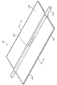
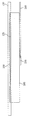
- FIG. 1 is a perspective view of an FBG sensor according to a first embodiment of the present invention
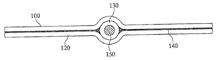
- FIG. 2 is a cross-sectional view taken along the line A-A in FIG. 1;
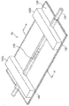
- FIG. 3 is a perspective view of an FBG sensor according to a second embodiment of the present invention.
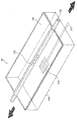
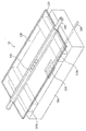
- FIG. 4 is a use state diagram briefly illustrating a state of measuring the maximum strain and the residual strain by attaching the first embodiment shown in FIG. 1 to the specimen CFRP (200),
- FIG. 5 is a side view of FIG. 4;
- FIG. 6 is a use state diagram briefly showing a state of measuring the maximum strain and the residual strain by attaching the second embodiment shown in FIG. 3 to the specimen CFRP (200),
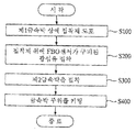
- FIG. 7 is a flowchart illustrating a manufacturing method of an FBG sensor according to an embodiment of the present invention.
- 11 is a graph of strain and residual strain measurement using the second embodiment of the present invention.
- the FBG sensor for measuring the maximum strain of the present invention the optical fiber 130 having the FBG sensor 150 therein, the first metal foil 100 is in contact with the optical fiber 130 on one surface, the first to interview the one surface 2, the residual strain of the first and second metal foils 100 and 120 is measured through the adhesive layer 140 provided between the metal foils 120, the first and second metal foils 100 and 120, and the FBG sensor 150.
- the FBG sensor 150 is located in the middle of the optical fiber 130.
- the first and second metal foils 100 and 120 are in contact with each other up and down around the FBG sensor 150.
- the first and second metal foils 100 and 120 and the optical fiber 130 are tightly bonded by the adhesive layer 140.
- the FBG sensor 150 is positioned at a central position.
- FIG. 1 is a perspective view of an FBG sensor 10 according to a first embodiment of the present invention
- Figure 2 is a cross-sectional view of the A-A direction in FIG. 1 and 2
- the FBG sensor 150 is located in the middle portion of the optical fiber 130.
- the first and second metal foils 100 and 120 are in contact with each other up and down around the FBG sensor 150.
- the first and second metal foils 100 and 120 and the optical fiber 130 are tightly bonded by the adhesive layer 140.
- Each of the first and second metal foils 100 and 120 may be an aluminum foil having a thickness of 10 ⁇ m to 30 ⁇ m. More preferably, the thickness may be in the range of 15 ⁇ m to 20 ⁇ m. A thickness of less than 10 ⁇ m is inconvenient to tear or difficult to manufacture, and when thicker than 30 ⁇ m, the elastic restoring force may increase, and thus, it may be difficult to accurately measure the residual strain.
- aluminum foil having a thickness of about 18 ⁇ m was used for the first and second metal foils 100 and 120, respectively. Therefore, the total thickness of the first and second metal foils 100 and 120 and the adhesive layer 140 is about 36 ⁇ m.
- steel foil or copper foil may be used.
- the FBG sensor 150 is positioned at a central position.
- FIG. 3 is a perspective view of the FBG sensor 20 according to the second embodiment of the present invention.
- the first and second metal foils 100 and 120, the adhesive layer 140, the optical fiber 130, the FBG sensor 150, and the like are the same as those of the first embodiment, and thus descriptions thereof will be omitted. do.
- the brackets 160a and 160b function to bond the first metal foil 100 and the measurement target 200.
- the brackets 160a and 160b are symmetrically disposed at positions spaced about 2.5 cm from side to side with respect to the FBG sensor 150.
- FIG. 7 is a flowchart illustrating a method of manufacturing an FBG sensor according to an embodiment of the present invention.
- an optical fiber 130 having an aluminum foil (first metal foil, 100) having a thickness of about 18 ⁇ m and an FBG sensor 150 having a length of about 1 cm may be prepared. do.
- an adhesive is applied to one surface of the aluminum foil (first metal foil) 100 to form an adhesive layer 140 (S100).
- the optical fiber 130 is bonded on the adhesive layer 140 so that the FBG sensor 150 is located at the center (S200).
- the same aluminum foil (second metal foil, 120) is covered and bonded on the aluminum foil (first metal foil, 100) (S300).
- one large aluminum foil can be folded in half to complete the S300 step.
- the periphery of the aluminum foil (first, second metal foil, 100, 120) is cut to a desired size and shape (for example, rectangular) to complete (S400).
- the optical fiber 130 is placed on the center line which is symmetrical.
- brackets 160a and 160b may be added as in the second embodiment illustrated in FIG. 3.
- the pair of brackets 160a and 160b are attached to each other by about 2.5 cm from the center by using epoxy resin.
- the sensitivity coefficient Csen between the maximum strain and the residual strain is defined as follows.
- e max is the maximum strain and e res is the residual strain.
- the FBG sensor and strain gauge according to the present invention are attached to a predetermined specimen and then subjected to a tensile test in a tensile tester.
- the sensitivity coefficient (Csen) is calculated from Equation 1 using the maximum strain (e max ) of the strain gauge measured at this time and the residual strain (e res ) of the FBG sensor measured after the tensile test.
- the maximum strain e max may be obtained from Equation 1 using the sensitivity coefficient Csen calculated in advance.
- FIG. 4 is a diagram illustrating a state in which the first embodiment illustrated in FIG. 1 is attached to the specimen CFRP 200 to briefly measure the maximum strain and the residual strain
- FIG. 5 is a side view of FIG. 4.
- a carbon fiber reinforced polymer (CFRP) is prepared as a predetermined specimen 200 for calculating the sensitivity coefficient Csen.
- Carbon fiber reinforced polymer (CFRP) is used as the main structural material in almost all commercialized modern aircraft.
- maximum strain detection is very important. This is because structural safety criteria can be determined from this information.
- the size of the carbon fiber reinforced polymer (CFRP) composite specimen 200 is 2 mm thick, 25 mm wide, and 150 mm long.
- An FBG sensor 10 bonded to an aluminum foil is attached to the top surface of the CFRP specimen 200 using an epoxy resin, and an electric strain gauge 250 having a length of 5 mm is attached to the bottom surface of the CFRP specimen 200.
- the signal of the strain gauge 250 is output through a separate wiring 260.
- the data of the FBG sensor 10 according to the present invention is obtained by an FBG interrogator (Cyronironi), and the data of the strain gauge 250 is a signal controller via an A / D transmitter (not shown). (Not shown).
- the strain was measured over 10 iterations for each load step. Each load step is 100 Kbf, and the load on the FBG sensor 10 on the specimen 200 is increased and the strain is repeated.
- FIG. 6 is a diagram illustrating a state in which the second embodiment illustrated in FIG. 3 is attached to the CFRP 200 as a specimen to briefly measure the maximum strain and the residual strain.
- FIGS. 8 to 11 the respective maximum strain and residual strain graphs for the first and second embodiments are shown in FIGS. 8 to 11. That is, FIG. 8 is a maximum strain measurement graph using the first embodiment of the present invention, FIG. 9 is a strain and residual strain measurement graph using the first embodiment of the present invention, and FIG. 10 is a second embodiment of the present invention. It is a maximum strain measurement graph using, Figure 11 is a strain and residual strain measurement graph using a second embodiment of the present invention. For reference, no residual strain could be obtained for the FBG sensor without metal foil.
- the residual strain remained from the second stage of the applied tensile force.
- the residual strain increased linearly. That is, the slopes of the maximum strain e max and the residual strain e res were 5.64 and 0.87, respectively, and the sensitivity coefficient Csen was calculated to be about 6.48 by Equation 1. Through this process, the sensitivity coefficient Csen may be calculated.
- the FBG sensor 10 according to the present invention is attached to an object to be measured, and the residual strain e res is obtained using the sensitivity coefficient Csen calculated through the above procedure.
- the maximum strain e max can be calculated.
- the strain was measured over five iterations in each step.
- the residual strain was measured from the fourth step.
- the strain showed linearity as in FIGS. 8 and 9.
- the slopes of the maximum strain e max and the residual strain e res were 2.69 and 0.319, respectively, in the same manner as in the experiments of FIGS. 8 and 9. Therefore, according to [Equation 1], the sensitivity coefficient Csen was calculated to be about 8.43.
- the difference between the experimental results of the first embodiment of FIGS. 8 and 9 and the second embodiment of FIGS. 10 and 11 is the ratio between the strain and the tensile force step.
- the sensitivity coefficient (Csen, 6.48) of the first embodiment (Figs. 8 and 9) is smaller than the sensitivity coefficient (Csen, 8.43) of the second embodiment (Figs. 10 and 11).
- This may be seen as related to the distance between the FBG sensor and the specimen 200. That is, in the case of the first embodiment (FIGS. 8 and 9), the distance between the FBG sensor and the specimen 200 is close so that the sensitivity coefficient Csen is small, and in the case of the second embodiment (FIGS. 10 and 11), the FBG Since the distance between the sensor and the specimen 200 is far, the sensitivity coefficient Csen is large.
- the residual strain (e res) (Fig. 8 and 9) is 0.87
- the residual strain (e res) of (10 and 11) is at least twice the difference as a 0.319 a It can be seen that. Therefore, the FBG sensors of the first and second embodiments can be appropriately applied and used depending on the size of the dispersion sensing field or the magnitude of the residual strain and the magnitude of the sensitivity coefficient.
- the FBG sensor described above is not limited to the configuration and method of the above-described embodiments, but the embodiments may be configured by selectively combining all or some of the embodiments so that various modifications can be made. have.
Landscapes
- General Physics & Mathematics (AREA)
- Physics & Mathematics (AREA)
- Chemical & Material Sciences (AREA)
- Analytical Chemistry (AREA)
- General Health & Medical Sciences (AREA)
- Life Sciences & Earth Sciences (AREA)
- Health & Medical Sciences (AREA)
- Biochemistry (AREA)
- Immunology (AREA)
- Pathology (AREA)
- Aviation & Aerospace Engineering (AREA)
- Engineering & Computer Science (AREA)
- Length Measuring Devices By Optical Means (AREA)
- Optical Transform (AREA)
- Measurement Of Length, Angles, Or The Like Using Electric Or Magnetic Means (AREA)
Abstract
Description

Claims (10)
- 내부에 FBG센서(150)가 구비된 광섬유(130);일면에 상기 광섬유(130)가 접해지는 제 1 금속박(100);상기 일면에 면접하는 제 2 금속박(120);상기 제 1, 2 금속박(100, 120) 사이에 구비되는 접착층(140);상기 FBG센서(150)를 통해 상기 제 1, 2 금속박(100, 120)의 잔류 변형률을 측정하는 수단; 및상기 측정된 잔류 변형률 값과 실험으로 구한 감도계수(Csen)에 기초하여 최대 변형률을 산출하는 수단;을 포함하는 것을 특징으로 하는 최대 변형률 측정을 위한 FBG 센서.
- 제 1 항에 있어서,상기 제 1, 2 금속박(100, 120)중 적어도 하나는 알루미늄 호일인 것을 특징으로 하는 최대 변형률 측정을 위한 FBG 센서.
- 제 1 항에 있어서,상기 제 1, 2 금속박(100, 120)중 적어도 하나의 두께는 10㎛ ~ 30 ㎛ 범위인 것을 특징으로 하는 최대 변형률 측정을 위한 FBG 센서.
- 제 1 항에 있어서,상기 제 1, 2 금속박(100, 120)중 적어도 하나는 상기 광섬유(130)의 길이방향을 따라 사각 형상인 것을 특징으로 하는 최대 변형률 측정을 위한 FBG 센서.
- 제 1 항에 있어서,상기 광섬유(130)는 상기 제 1, 2 금속박(100, 120)중 적어도 하나의 중심선상에 위치하는 것을 특징으로 하는 최대 변형률 측정을 위한 FBG 센서.
- 제 1 항에 있어서,상기 제 1, 2 금속박(100, 120)중 어느 하나의 일면과 측정대상을 연결하기 위한 브라켓을 더 포함하는 것을 특징으로 하는 최대 변형률 측정을 위한 FBG 센서.
- 제 6 항에 있어서,상기 브라켓은 상기 FBG 센서(150)를 중심으로 대칭적으로 위치하는 한쌍의 브라켓(160a, 160b)인 것을 특징으로 하는 최대 변형률 측정을 위한 FBG 센서.
- 제 1 금속박(100)의 일면에 접착제를 도포하여 접착층(140)을 성막하는 단계(S100);상기 접착제 위에 FBG 센서(150)가 구비된 광섬유(130)를 접착시키는 단계(S200); 및상기 제 1 금속박(100)의 일면에 제 2 금속박(120)을 접착시키는 단계(S300);를 포함하는 것을 특징으로 하는 최대 변형률 측정을 위한 FBG 센서의 제조방법.
- 제 8 항에 있어서,상기 제 1, 2 금속박(100, 120)을 원하는 형상으로 커팅하는 단계(S400)를 더 포함하는 것을 특징으로 하는 최대 변형률 측정을 위한 FBG 센서의 제조방법.
- 제 1 금속박(100)의 일면에 접착제를 도포하여 접착층(140)을 성막하는 단계(S100); 상기 접착제 위에 FBG 센서(150)가 구비된 광섬유(130)를 접착시키는 단계(S200); 상기 제 1 금속박(100)의 일면에 제 2 금속박(120)을 접착시키는 단계(S300); 및 상기 제 1, 2 금속박(100, 120)을 원하는 형상으로 커팅하는 단계(S400);에 의해 제조된 FBG 센서를 측정대상에 부착하는 단계;상기 측정대상이 변형되는 동안 또는 변형된 후 상기 광섬유(130)에 소정의 입력신호를 입력시키는 단계;상기 입력신호에 기반한 상기 FBG 센서(150)의 출력신호를 측정하는 단계;상기 출력신호에 기초하여 상기 측정대상의 잔류 변형률을 측정하는 단계; 및측정된 잔류 변형률 값과 실험으로 구한 감도계수(Csen)를 이용하여 최대 변형률을 산출하는 단계;를 포함하는 것을 특징으로 하는 최대 변형률 측정을 위한 FBG 센서의 사용방법.
Priority Applications (4)
| Application Number | Priority Date | Filing Date | Title |
|---|---|---|---|
| JP2016519340A JP6139026B2 (ja) | 2013-10-01 | 2014-09-30 | 最大歪率測定のためのfbgセンサ、その製造方法及び使用方法 |
| CN201480059010.0A CN105683705B (zh) | 2013-10-01 | 2014-09-30 | 用于测量最大应变的fbg传感器、制造方法和使用方法 |
| US15/025,334 US9791335B2 (en) | 2013-10-01 | 2014-09-30 | FBG sensor for measuring maximum strain, manufacturing method and using method |
| DE112014004544.6T DE112014004544B4 (de) | 2013-10-01 | 2014-09-30 | FBG-Sensor zur Messung maximaler Dehnung, Herstellungsverfahren und Verwendungsverfahren |
Applications Claiming Priority (2)
| Application Number | Priority Date | Filing Date | Title |
|---|---|---|---|
| KR10-2013-0117106 | 2013-10-01 | ||
| KR1020130117106A KR101465156B1 (ko) | 2013-10-01 | 2013-10-01 | 최대 변형률 측정을 위한 fbg 센서, 제조방법 및 사용방법 |
Publications (1)
| Publication Number | Publication Date |
|---|---|
| WO2015050355A1 true WO2015050355A1 (ko) | 2015-04-09 |
Family
ID=52291579
Family Applications (1)
| Application Number | Title | Priority Date | Filing Date |
|---|---|---|---|
| PCT/KR2014/009159 Ceased WO2015050355A1 (ko) | 2013-10-01 | 2014-09-30 | 최대 변형률 측정을 위한 fbg 센서, 제조방법 및 사용방법 |
Country Status (6)
| Country | Link |
|---|---|
| US (1) | US9791335B2 (ko) |
| JP (1) | JP6139026B2 (ko) |
| KR (1) | KR101465156B1 (ko) |
| CN (1) | CN105683705B (ko) |
| DE (1) | DE112014004544B4 (ko) |
| WO (1) | WO2015050355A1 (ko) |
Cited By (1)
| Publication number | Priority date | Publication date | Assignee | Title |
|---|---|---|---|---|
| CN107300363A (zh) * | 2016-05-12 | 2017-10-27 | 中国计量大学 | 一种正四面体光纤光栅三维应变检测结构体 |
Families Citing this family (15)
| Publication number | Priority date | Publication date | Assignee | Title |
|---|---|---|---|---|
| CA2967991A1 (en) * | 2016-05-19 | 2017-11-19 | Kidde Technologies, Inc. | Optical health monitoring for aircraft overheat and fire detection systems |
| CN106013276A (zh) * | 2016-07-04 | 2016-10-12 | 中国电建集团华东勘测设计研究院有限公司 | 海上风机大直径钢管桩应力应变测试系统及施工方法 |
| DE102016014280B4 (de) * | 2016-11-30 | 2018-07-12 | Hottinger Baldwin Messtechnik Gmbh | Anschweißbare FBG-Dehnungssensoranordnung |
| US10782191B2 (en) * | 2018-03-06 | 2020-09-22 | Kidde Technologies, Inc. | Method to isolate individual channels in a multi-channel fiber optic event detection system |
| JP6873073B2 (ja) * | 2018-03-08 | 2021-05-19 | 三菱重工業株式会社 | 評価方法及び評価システム |
| AT522927B1 (de) * | 2019-08-23 | 2022-04-15 | Ait Austrian Inst Tech Gmbh | Verfahren zur Detektion der maximalen Ausdehnung von Rissen in einem Objekt |
| US11682282B2 (en) | 2020-02-10 | 2023-06-20 | Kidde Technologies, Inc. | Fiber Bragg grating-based advance pneumatic fire/overheat detector |
| JP7334664B2 (ja) * | 2020-04-02 | 2023-08-29 | 株式会社島津製作所 | 応力発光測定方法および応力発光測定装置 |
| CN111579051A (zh) * | 2020-05-18 | 2020-08-25 | 武汉理工大学 | 一种光纤覆金属箔的水声压增敏装置 |
| JP2024540968A (ja) * | 2021-10-20 | 2024-11-06 | ルナ イノベーションズ インコーポレイテッド | 光ファイバ感知システムにおけるファイバ挿入損失の測定 |
| CN114509016B (zh) * | 2021-12-24 | 2024-03-29 | 北京遥测技术研究所 | 一种高温efpi型光纤应变传感器及其制备方法 |
| KR102677582B1 (ko) * | 2022-02-21 | 2024-06-21 | 주식회사 카이스 | 광섬유를 이용한 변위 센서 |
| CN115854900B (zh) * | 2022-11-04 | 2026-04-21 | 同济大学 | 一种刚性道面翘曲变形在线监测方法、设备、介质 |
| DE102023203725B4 (de) | 2023-04-24 | 2025-05-28 | Fraunhofer-Gesellschaft zur Förderung der angewandten Forschung eingetragener Verein | Bauteil zur Erfassung von Kraft- und Dehnungsfeldern und Verfahren zur Herstellung eines Bauteils zur Erfassung von Kraft- und Dehnungsfeldern |
| CN120284245B (zh) * | 2025-06-06 | 2025-09-09 | 浙江大学 | 一种弯曲传感器及其制备方法 |
Citations (3)
| Publication number | Priority date | Publication date | Assignee | Title |
|---|---|---|---|---|
| JP2003130934A (ja) * | 2001-10-26 | 2003-05-08 | Hitachi Cable Ltd | 光ファイバ磁気センサ |
| JP2003254838A (ja) * | 2002-03-04 | 2003-09-10 | Furukawa Electric Co Ltd:The | 光式温度センサー |
| JP2007255894A (ja) * | 2006-03-20 | 2007-10-04 | Tokyo Sokki Kenkyusho Co Ltd | Fbg式ひずみゲージ |
Family Cites Families (15)
| Publication number | Priority date | Publication date | Assignee | Title |
|---|---|---|---|---|
| JP2001296110A (ja) * | 2000-04-17 | 2001-10-26 | Ntt Advanced Technology Corp | 貼り付け型光ファイバセンサ |
| US7369729B2 (en) | 2001-09-13 | 2008-05-06 | Fujikura Ltd. | Optical fiber sheet and optical fiber sheet production method |
| JP3811761B2 (ja) | 2002-03-26 | 2006-08-23 | エヌ・ティ・ティ・アドバンステクノロジ株式会社 | ファイバ型ブラッググレーティング素子及びその製造方法 |
| JP2004012714A (ja) * | 2002-06-05 | 2004-01-15 | Sumitomo Electric Ind Ltd | 分散補償器用のパッケージ部材および分散補償器 |
| CN2651704Y (zh) * | 2003-11-04 | 2004-10-27 | 刘育梁 | 光纤光栅应变传感器 |
| JP4102291B2 (ja) | 2003-11-17 | 2008-06-18 | 独立行政法人 宇宙航空研究開発機構 | Ofdr方式の歪連続分布計測装置 |
| JP2006194704A (ja) * | 2005-01-12 | 2006-07-27 | Kyowa Electron Instr Co Ltd | 溶接型光ひずみゲージとその製造方法および溶接型光ひずみゲージユニット |
| JP2007225894A (ja) | 2006-02-23 | 2007-09-06 | Matsushita Electric Works Ltd | 光結合部品及びその製造方法 |
| DE102007048817B4 (de) | 2007-10-10 | 2016-06-30 | Airbus Defence and Space GmbH | Sensor zum Messen von Spannungen in einem Substrat |
| US7856888B2 (en) * | 2007-11-15 | 2010-12-28 | Micron Optics Inc. | Fiber optic strain gage and carrier |
| US7796844B2 (en) * | 2008-07-22 | 2010-09-14 | The Hong Kong Polytechnic University | Temperature-compensated fibre optic strain gauge |
| JP5258683B2 (ja) | 2009-06-26 | 2013-08-07 | 株式会社東芝 | 材料劣化診断装置及び方法 |
| JP2012122751A (ja) | 2010-12-06 | 2012-06-28 | Toshiba Corp | 材料劣化診断装置 |
| JP5747408B2 (ja) | 2011-04-19 | 2015-07-15 | 公益財団法人地球環境産業技術研究機構 | 物体の体積変化計測方法 |
| WO2013071914A1 (de) * | 2011-11-15 | 2013-05-23 | Hottinger Baldwin Messtechnik Gmbh | Fbg-dehnungssensor für gekrümmte oberflächen |
-
2013
- 2013-10-01 KR KR1020130117106A patent/KR101465156B1/ko not_active Expired - Fee Related
-
2014
- 2014-09-30 DE DE112014004544.6T patent/DE112014004544B4/de active Active
- 2014-09-30 CN CN201480059010.0A patent/CN105683705B/zh active Active
- 2014-09-30 JP JP2016519340A patent/JP6139026B2/ja not_active Expired - Fee Related
- 2014-09-30 WO PCT/KR2014/009159 patent/WO2015050355A1/ko not_active Ceased
- 2014-09-30 US US15/025,334 patent/US9791335B2/en not_active Expired - Fee Related
Patent Citations (3)
| Publication number | Priority date | Publication date | Assignee | Title |
|---|---|---|---|---|
| JP2003130934A (ja) * | 2001-10-26 | 2003-05-08 | Hitachi Cable Ltd | 光ファイバ磁気センサ |
| JP2003254838A (ja) * | 2002-03-04 | 2003-09-10 | Furukawa Electric Co Ltd:The | 光式温度センサー |
| JP2007255894A (ja) * | 2006-03-20 | 2007-10-04 | Tokyo Sokki Kenkyusho Co Ltd | Fbg式ひずみゲージ |
Non-Patent Citations (1)
| Title |
|---|
| KIM, S.W. ET AL.: "Determination of the maximum strains experienced by composite structures using metal coated optical fiber sensors", COMPOSITE SCIENCE AND TECHNOLOGY, vol. 78, April 2013 (2013-04-01), pages 48 - 55 * |
Cited By (1)
| Publication number | Priority date | Publication date | Assignee | Title |
|---|---|---|---|---|
| CN107300363A (zh) * | 2016-05-12 | 2017-10-27 | 中国计量大学 | 一种正四面体光纤光栅三维应变检测结构体 |
Also Published As
| Publication number | Publication date |
|---|---|
| CN105683705A (zh) | 2016-06-15 |
| DE112014004544T5 (de) | 2016-07-07 |
| US20160216166A1 (en) | 2016-07-28 |
| JP2016540188A (ja) | 2016-12-22 |
| KR101465156B1 (ko) | 2014-11-26 |
| US9791335B2 (en) | 2017-10-17 |
| DE112014004544B4 (de) | 2021-12-16 |
| CN105683705B (zh) | 2019-04-16 |
| JP6139026B2 (ja) | 2017-05-31 |
Similar Documents
| Publication | Publication Date | Title |
|---|---|---|
| WO2015050355A1 (ko) | 최대 변형률 측정을 위한 fbg 센서, 제조방법 및 사용방법 | |
| US7333696B2 (en) | Tape-shaped optical fiber cable | |
| JP2983018B1 (ja) | 光ファイバセンサ | |
| US7856888B2 (en) | Fiber optic strain gage and carrier | |
| EP0640824A1 (en) | Fibre optic damage detection system | |
| WO2003076887A1 (en) | Fiber optic sensor package | |
| CA2338409A1 (en) | Patch type optical fiber sensor | |
| US20070116402A1 (en) | Humidity sensor and method for monitoring moisture in concrete | |
| KR101529610B1 (ko) | 민감도가 제어된 fbg 탐촉자, fbg 탐촉자 센싱 시스템 및 그 센싱방법과 제조방법 | |
| CN107121158B (zh) | 一种内封式悬臂梁光纤光栅传感器 | |
| WO2010129942A1 (en) | Cable including strain-free fiber and strain-coupled fiber | |
| KR20110122443A (ko) | 다축 변형률 측정이 가능한 필름형 광섬유 브래그 격자 센서 패키지 | |
| KR20120090010A (ko) | 광섬유 브래그 회절격자를 갖는 광학 인장 측정장치 | |
| US20070065071A1 (en) | Humidity sensor and method for monitoring moisture in concrete | |
| CN104199159A (zh) | 同时监测温度和应变的扁平型带状传感光缆 | |
| IT201900008874A1 (it) | Metodo e sistema per rilevare e misurare una forza di frenata di un sistema frenante per veicolo, mediante sensori fotonici incorporati in una pastiglia freno | |
| CN109901272A (zh) | 一种多芯光纤智能复合筋、制备方法以及安全监测方法 | |
| CN111811685A (zh) | 一种光纤光栅温度传感器、组件及制作方法 | |
| CN110319949B (zh) | 一种分布式温度应变传感光缆及测量方法 | |
| EP4130650B1 (en) | Optical-fiber-embedding sheet, method for placing optical fiber, and application device | |
| US20070058898A1 (en) | Humidity sensor and method for monitoring moisture in concrete | |
| US20130265564A1 (en) | Optical strain gauge | |
| CN120800244A (zh) | 一种光纤光栅挠度传感系统及其制作方法 | |
| CN103162876A (zh) | 壳构件应力的光纤监测装置 | |
| Ramos et al. | Design of an optical fibre sensor patch for longitudinal strain measurement in structures |
Legal Events
| Date | Code | Title | Description |
|---|---|---|---|
| 121 | Ep: the epo has been informed by wipo that ep was designated in this application |
Ref document number: 14851086 Country of ref document: EP Kind code of ref document: A1 |
|
| WWE | Wipo information: entry into national phase |
Ref document number: 15025334 Country of ref document: US |
|
| ENP | Entry into the national phase |
Ref document number: 2016519340 Country of ref document: JP Kind code of ref document: A |
|
| WWE | Wipo information: entry into national phase |
Ref document number: 1120140045446 Country of ref document: DE Ref document number: 112014004544 Country of ref document: DE |
|
| 122 | Ep: pct application non-entry in european phase |
Ref document number: 14851086 Country of ref document: EP Kind code of ref document: A1 |