WO2015046942A1 - 관통 저항성이 향상된 열교환기용 알루미늄 합금, 이를 포함하는 관통 저항성이 향상된 알루미늄 압출 튜브와 핀 재 및 이로 구성된 열교환기 - Google Patents
관통 저항성이 향상된 열교환기용 알루미늄 합금, 이를 포함하는 관통 저항성이 향상된 알루미늄 압출 튜브와 핀 재 및 이로 구성된 열교환기 Download PDFInfo
- Publication number
- WO2015046942A1 WO2015046942A1 PCT/KR2014/009003 KR2014009003W WO2015046942A1 WO 2015046942 A1 WO2015046942 A1 WO 2015046942A1 KR 2014009003 W KR2014009003 W KR 2014009003W WO 2015046942 A1 WO2015046942 A1 WO 2015046942A1
- Authority
- WO
- WIPO (PCT)
- Prior art keywords
- corrosion
- heat exchanger
- aluminum
- aluminum alloy
- fin material
- Prior art date
- Legal status (The legal status is an assumption and is not a legal conclusion. Google has not performed a legal analysis and makes no representation as to the accuracy of the status listed.)
- Ceased
Links
Images




Classifications
-
- C—CHEMISTRY; METALLURGY
- C22—METALLURGY; FERROUS OR NON-FERROUS ALLOYS; TREATMENT OF ALLOYS OR NON-FERROUS METALS
- C22C—ALLOYS
- C22C21/00—Alloys based on aluminium
Definitions
- the present invention relates to an aluminum alloy for a heat exchanger having improved penetration resistance, an aluminum extrusion tube and a fin material for a heat exchanger having improved penetration resistance, and a heat exchanger including the same, and more particularly, a refrigerant in a heat exchanger such as an air conditioner, a refrigerator, a radiator, and the like. And an extruded aluminum tube for heat exchanger and a fin material and a heat exchanger having improved penetration resistance and corrosion durability, which inhibit penetration and damage of a material caused by corrosion damage caused by external condensate.
- heat exchanger materials have been replaced from copper to aluminum due to cost, ease of processing, and corrosion resistance. This is because aluminum is light, low in price, and has high thermal conductivity.
- pure aluminum base As the aluminum material for heat exchanger, pure aluminum base (A1XXX), which is advantageously extruded, has high thermal conductivity, and is inexpensive, and extrudeability is slightly lower than pure aluminum base, but has relatively high strength and corrosion resistance (A3XXX) ) Is used.
- Table 1 shows the compositions of A1070 and A3003 which are conventionally mainly used as aluminum materials for heat exchangers.
- A1070 is pure aluminum-based material and A3003 is aluminum-manganese-based material.
- Table 1 Material name Cu Si Fe Zn Mg Mn Ti Al. A1070 0.03 0.20 0.25 0.04 0.03 0.03 0.03 Rem. A3003 0.158 0.084 0.421 0.034 0.001 1.021 0.014 Rem.
- the A1070 material is used as a tube and fin material such as condensers of home appliances such as air conditioners and refrigerators, where high strength is not required because of low material price and extrusion cost.
- the A3003 material is used as an extruded tube and fin material for heat exchangers such as automotive intercoolers and radiators due to its relatively high strength and corrosion resistance compared to A1070 but higher extrusion cost.
- aluminum is a metal which is easy to be activated, but forms an oxide film on the surface in air and has high corrosion resistance.
- a pitting corrosion will occur only in the localized area where the oxide film is damaged.
- corrosion is intensively propagated to a part by electrochemical action with various impurities contained in the aluminum alloy. Due to the corrosion mechanism of the aluminum, the aluminum heat exchanger is locally penetrated to leak the refrigerant or the high temperature fluid therein. Therefore, there is an urgent need for development of an aluminum alloy material for heat exchangers having improved penetration resistance.
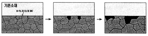
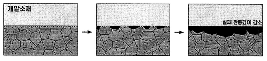
- FIG. 1 shows a formula and intergranular corrosion mechanism of a conventional aluminum material.
- a protective passive film is formed on the aluminum surface, and Al 2 Cu, Al 3 Fe, and the like are formed on the intermetallic face ( It is distributed at grain boundaries by intermetallic phase.
- the potential difference between the intermetallic face such as Al 2 Cu and Al 3 Fe and the base material is generated as shown in the middle drawing, and a local circuit is formed to form a passive film. You can see that the formula begins when it is destroyed.
- the formula then propagates as far right as the formula propagates along the grain boundary faster than the onset of the new formulation at the surface, which results in a very high penetration depth versus actual corrosion. Therefore, due to the corrosion mechanism of aluminum, the aluminum heat exchanger is locally penetrated to cause leakage of refrigerant or high temperature fluid therein.
- Figure 2 is a view showing the corrosion propagation behavior of aluminum used as a conventional heat exchanger material, it can be seen that the penetration depth is very high due to the propagation of the formula over time as shown in the figure.
- One object of the present invention unlike the A1070 and A3003 material used as a tube and fin material of the conventional heat exchanger, to add a zirconium (Zr) to disperse the occurrence of corrosion to induce a uniform corrosion, and to control the composition ratio of the material It is thereby to provide an aluminum alloy composition which improves penetration resistance and corrosion durability and at the same time does not lower the extrudability.
- Zr zirconium
- Aluminum alloy for heat exchangers with improved penetration resistance according to an embodiment of the present invention, 0.05% to 0.17% by weight of zirconium (Zr); More than 0 wt% copper (Cu); More than 0% by weight and 0.2% by weight or less of the silicon (Si); More than 0% and 0.2% by weight of said iron (Fe); And the balance of aluminum (Al) and indispensable impurities.
- the present invention provides an aluminum tube for heat exchanger with improved corrosion durability, aluminum fin material for heat exchanger with improved corrosion durability made of the aluminum alloy as described above.
- the present invention provides a heat exchanger with improved corrosion durability including the aluminum tube for heat exchanger with improved corrosion durability, the aluminum fin material for heat exchanger with improved corrosion durability.
- the present invention having the configuration as described above has excellent penetration resistance and corrosion durability compared to A1070, which is a conventional aluminum material for heat exchangers, and excellent resistance to corrosion damage and penetration by external condensate and internal refrigerant. Specifically, the addition of zirconium (Zr) induces uniform corrosion to occur, thereby increasing the penetration resistance of the material compared to the formula.
- Zr zirconium
- the present invention has the effect of inhibiting grain boundary corrosion due to the concentration control of copper (Cu) to disperse the propagation of corrosion to increase the penetration resistance of the material.
- the effects of the present invention having the configuration described above shows a similar extrusion speed (a level of 90 m / min) compared to the A1070, which is a conventional aluminum material for heat exchangers, and thus has excellent productivity and economy.
- FIG. 1 is a schematic diagram illustrating a formula and grain boundary corrosion mechanism of a conventional aluminum material.
- FIG. 2 is a view showing the corrosion propagation behavior of aluminum used as a conventional heat exchanger material.
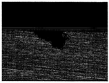
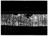
- 3A and 3B are cross-sectional views of the electrostatic potential polarization test of the A1070 specimen of 1XXX-based aluminum, which is used as a conventional heat exchanger material.
- Figures 4a and 4b is a view showing a cross-section after the potential potential polarization test of the A3003 specimen of 3XXX-based aluminum used as a conventional heat exchanger material.
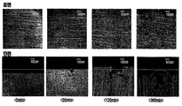
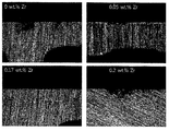
- Figure 6 shows a photograph of the change in the corrosion depth of the aluminum alloy according to an embodiment of the present invention according to the zirconium content.
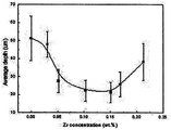
- Figure 7 shows a graph of the change in the corrosion penetration depth of the aluminum alloy according to an embodiment of the present invention according to the content of zirconium.
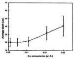
- Figure 8 shows a photograph of the change in the corrosion depth of the aluminum alloy according to an embodiment of the present invention depending on the copper content.
- Figure 9 shows a graph of the change in the corrosion depth of the aluminum alloy according to an embodiment of the present invention according to the copper content.
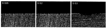
- FIG. 10 shows a photograph of the change in the corrosion depth of the aluminum alloy according to an embodiment of the present invention according to the silicon content.
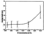
- Figure 11 shows a graph of the change in the corrosion depth of the aluminum alloy according to an embodiment of the present invention according to the silicon content.
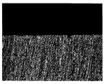
- Figure 12 shows a photograph of the change in the corrosion depth of the aluminum alloy according to an embodiment of the present invention according to the iron content.
- Figure 13 shows a graph of the change in the corrosion depth of the aluminum alloy according to an embodiment of the present invention depending on the iron content.
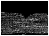
- FIG 14 is a view showing a cross section after the potential potential polarization test of the specimen made of an aluminum alloy composition according to an embodiment of the present invention.
- the aluminum alloy composition for heat exchanger having improved penetration resistance includes zirconium (Zr), copper (Cu), silicon (Si), iron (Fe), balance aluminum (Al) and essential impurities. Include.
- Such zirconium (Zr), copper (Cu), silicon (Si), iron (Fe) may be controlled to a predetermined concentration or less, respectively.
- Zirconium (Zr) is preferably controlled to 0.05% to 0.17% by weight
- copper (Cu) is preferably controlled to 0.01% by weight or less
- silicon (Si) is preferably controlled to 0.2% by weight or less.
- Iron (Fe) is preferably controlled to 0.2% by weight or less.
- the aluminum alloy for heat exchanger having improved penetration resistance is characterized in that it comprises zirconium (Zr), these components not only improve the strength by miniaturizing the grain size (Grain Size), By generating a potential difference, finely dispersing the precipitates acting as the initiation point of corrosion inhibits the occurrence of pitting corrosion, a form of locally violent unpredictable corrosion, and induces uniform corrosion.
- Zr zirconium
- the zirconium is included in about 0.05% by weight or more.
- the zirconium is preferably included in about 0.17% by weight or less in order to suppress the occurrence of cracks and improve the extrudability of the material.
- FIG. 5 It is a schematic diagram explaining the formula and grain boundary corrosion mechanism of the aluminum material of this invention.
- the aluminum alloy developed by the present invention reduces the distribution of Al 2 Cu, Al 3 Fe, etc. at grain boundaries in an intermetallic phase by inducing zirconium (Zr) and induces dispersion. Done.
- Zr zirconium
- each component is the content of each component expressed in weight percent
- Table 2 shows the average depth of corrosion and the depth of corrosion while only controlling the content of the remaining components and changing only the content of zirconium in order to determine the optimal zirconium content. Standard deviation is shown.
- the value of the average corrosion depth according to the content of zirconium shows a low value only in a certain section (0.05% to 0.17% by weight) of the content of zirconium and high values in other sections could. If the average corrosion depth exceeds 40um, it may correspond to the depth at which penetration occurs. In addition, as shown in Figure 6, but the content of zirconium content of 0.05% by weight and 0.17% by weight of similar corrosion penetration depth (about 20um), but less than 0.05% and more than 0.17% by weight Corrosion penetration depth was greatly increased (about 40um and above).
- the content of zirconium is a very important point in the present invention controls the content of zirconium (Zr) to 0.05% to 0.17% by weight.
- the mother alloy was dissolved and stirred at a temperature of about 730 ° C, injected into a plate mold preheated to 150 ° C, and cast, and boron nitride was applied as a release agent.
- the exposed area of 1cm 2 was controlled and artificial acid rain (4ppm SO 4 2- , 2.5 ppm NO2-, 1.7 ppm Cl-, pH 5)
- 0.25 V vs. Potential acceleration was performed at the potential of SCE. After the corrosion accelerated specimens were mounted, the corrosion accelerated points were cut at 0.25 cm intervals to obtain four corrosion accelerated cross sections, and the corrosion pattern and corrosion penetration depth were measured by optical microscopy.
- the element when another element is intentionally injected into the metal, the element is called an alloy element, and is inevitably injected due to technical and economical problems in the manufacturing process, and its existence is recognized by limiting the content to an allowable amount or less.
- the limiting amount of the impurity element depends on the degree of harmfulness of the impurity to the metal.
- Copper (Cu), silicon (Si), and iron (Fe) included in the aluminum alloy for heat exchanger having improved penetration resistance of the present invention generate impurities that are susceptible to corrosion as impurities unnecessarily contained in aluminum, and cathodic reaction in a corrosive environment. It is necessary to control the content.
- copper (Cu) is precipitated as Al2Cu, which combines with aluminum to promote the cathodic reaction of corrosion, and mainly because of the continuous distribution along the aluminum grain boundary, the corrosion damage propagates along the grain boundary. Since the aluminum material for the heat exchanger is vulnerable to penetrating as a cause, to control it, the aluminum material should be controlled to a high capacity or less at room temperature. In the present invention, the content of copper (Cu) is controlled to more than 0% by weight and about 0.01% by weight or less.
- the corrosion test was carried out under the conditions shown in the table below while changing the concentration of copper with almost uniform concentrations of silicon, iron, and zirconium, and the results were shown in the table below. .
- the content of copper is a very important point in the present invention, the content of copper (Cu) is controlled to more than 0% by weight to about 0.01% by weight or less.
- the content of silicon (Si) needs to be minimized.
- the content of silicon (Si) is 0% by weight. Greater than about 0.2% by weight.
- the content of silicon is a very important point in the present invention, the content of silicon (Si) is controlled to more than 0% by weight to about 0.2% by weight or less.
- iron (Fe) combines with aluminum (Al) and silicon (Si) to form precipitates and acts as a starting point for cathodic reactions in a corrosive environment, which plays a critical role in the corrosion of aluminum. Since the precipitates are discontinuously distributed, the risk of intergranular corrosion is lower than that of copper (Cu) and a high cost is generated to remove them below a low concentration. Therefore, in the present invention, the content of iron (Fe) is 0% by weight. Greater than about 0.2% by weight.
- the iron content is a very important point in the present invention controls the content of iron (Fe) to more than 0% by weight to about 0.2% by weight or less.
- FIGS. 4A and 4B are cross-sectional views of the electrostatic potential polarization test of the A1070 specimen of 1XXX aluminum, which is used as a conventional heat exchanger material
- FIGS. 4A and 4B are 3XXX aluminum, which is used as a conventional heat exchanger material.
- FIG. 14 is a cross-sectional view showing the cross-section after the potentiometric polarization test of the specimen A3003, FIG.
- composition of the aluminum alloy according to an embodiment of the present invention shown in Figure 14 is Zr, Cu, Si, Fe content of each component of Zr 0.15% by weight, Cu 0.01% by weight, Si 0.2% by weight, Fe 0.2% by weight % Was included.
- the electrostatic potential polarization test is useful for evaluating the corrosion resistance and corrosion resistance of the material by applying and maintaining a constant potential on the specimen to accelerate corrosion.
- the electrostatic potential polarization test was performed using an artificial acid ratio, which is an environment for simulating external condensate. After proceeding, the cross section of the specimen was observed to compare the depth of corrosion.
- the corrosion in the case of the A1070 and A3003 specimens, the corrosion is concentrated and propagated inward along the grain boundary in comparison with the reference line (red line).
- the corrosion in the case of the specimen having the composition of the present invention, the corrosion was dispersed based on the baseline of the surface and the grain boundary corrosion did not occur, so that the corrosion proceeded in a uniform form and the penetration depth was reduced, which is the A1070 specimen and the A3003 specimen. This means that the degree of corrosion progress is greatly reduced.
- Table 6 is a table measuring the corrosion depth after the potential potential polarization test for the A1070 specimens, A3003 specimens and the specimens (invention alloy) made of the aluminum alloy composition according to an embodiment of the present invention.
- the composition of the aluminum alloy of the present invention used an alloy containing a content of Zr, Cu, Si, and Fe contained 0.15% by weight of Zr, 0.01% by weight of Cu, 0.2% by weight of Si, and 0.2% by weight of Fe. .
- the average corrosion depth of the A1070 specimens was 139.14 ⁇ m.
- the average corrosion depth of the A3003 specimens was 96.49 ⁇ m.
- the specimen (invented alloy) prepared from the aluminum alloy composition according to the embodiment of the present invention had an average corrosion depth of 21.19 ⁇ m. That is, the specimen (invention alloy) made of the aluminum alloy composition according to an embodiment of the present invention has improved corrosion resistance by about five times or more than the A1070 specimens, and the corrosion progresses uniformly through the lower variation in corrosion depth. It can be seen that the penetration resistance against.
- the aluminum alloy composition according to an embodiment of the present invention showed an extrusion speed of about 90 m per minute. This is equivalent to about 90 m / min of the conventional A1070 and higher than about 60-70 m / min of the A3003. That is, the aluminum alloy composition according to the embodiment of the present invention showed a higher extrudability than the conventional A3003.
- the aluminum alloy composition according to the embodiment of the present invention can be used as the fin material of the heat exchanger as well as the extrusion tube.
- Heat exchangers consisting of extruded tubes and fins are structurally stacked, tube type and drawon cap type.
- the tube type pins therein or increases the amount of heat generated by the porous tube.
- the extruded tube is preassembled to a fin, a plate, a side tank, etc., and then fixed with a clamp, fluxed, and passed through a brazing furnace to prepare a heat exchanger.
- the penetration resistance of the heat exchanger to which the heat exchanger is applied is increased to increase the service life of components and to improve performance.
Landscapes
- Chemical & Material Sciences (AREA)
- Engineering & Computer Science (AREA)
- Materials Engineering (AREA)
- Mechanical Engineering (AREA)
- Metallurgy (AREA)
- Organic Chemistry (AREA)
- Preventing Corrosion Or Incrustation Of Metals (AREA)
Abstract
Description
| 소재명 | Cu | Si | Fe | Zn | Mg | Mn | Ti | Al. |
| A1070 | 0.03 | 0.20 | 0.25 | 0.04 | 0.03 | 0.03 | 0.03 | Rem. |
| A3003 | 0.158 | 0.084 | 0.421 | 0.034 | 0.001 | 1.021 | 0.014 | Rem. |
| Cu (고정) | Si (고정) | Fe (고정) | Zr (변화) | 부식 깊이 평균(um) | 부식 깊이 표준편차 | |
| 1 | 0.010 | 0.201 | 0.207 | 0 | 51.21 | 12.24 |
| 2 | 0.011 | 0.197 | 0.205 | 0.031 | 47.89 | 7.21 |
| 3 | 0.012 | 0.198 | 0.202 | 0.052 | 27.54 | 6.34 |
| 4 | 0.012 | 0.202 | 0.204 | 0.103 | 22.24 | 5.71 |
| 5 | 0.009 | 0.204 | 0.197 | 0.151 | 21.19 | 5.64 |
| 6 | 0.009 | 0.209 | 0.197 | 0.169 | 25.71 | 6.87 |
| 7 | 0.013 | 0.199 | 0.202 | 0.213 | 38.27 | 10.27 |
| Cu (변화) | Si (고정) | Fe (고정) | Zr (고정) | 부식 깊이 평균(um) | 부식 깊이 표준편차 | |
| 1 | 0.001 | 0.201 | 0.199 | 0.154 | 20.42 | 5.11 |
| 2 | 0.005 | 0.198 | 0.203 | 0.150 | 20.37 | 4.90 |
| 3 | 0.011 | 0.197 | 0.205 | 0.151 | 21.19 | 5.64 |
| 4 | 0.021 | 0.199 | 0.202 | 0.149 | 32.14 | 8.51 |
| 5 | 0.030 | 0.202 | 0.201 | 0.148 | 41.24 | 12.62 |
| Cu (고정) | Si (변화) | Fe (고정) | Zr (고정) | 부식 깊이 평균(um) | 부식 깊이 표준편차 | |
| 1 | 0.011 | 0.015 | 0.201 | 0.154 | 19.98 | 5.01 |
| 2 | 0.009 | 0.049 | 0.199 | 0.152 | 21.53 | 7.27 |
| 3 | 0.010 | 0.102 | 0.202 | 0.148 | 21.29 | 6.24 |
| 4 | 0.011 | 0.197 | 0.205 | 0.151 | 21.19 | 5.64 |
| 5 | 0.011 | 0.298 | 0.210 | 0.149 | 43.43 | 16.69 |
| Cu (고정) | Si (고정) | Fe (변화) | Zr (고정) | 부식 깊이 평균(um) | 부식 깊이 표준편차 | |
| 1 | 0.011 | 0.201 | 0.054 | 0.154 | 20.99 | 6.76 |
| 2 | 0.011 | 0.202 | 0.110 | 0.148 | 20.47 | 5.38 |
| 3 | 0.011 | 0.197 | 0.205 | 0.151 | 21.19 | 5.64 |
| 4 | 0.010 | 0.204 | 0.301 | 0.148 | 47.25 | 13.48 |
| 부식감육깊이 (㎛) | |||
| A1070 | A3003 | 발명합금 | |
| 평균 | 139.14 | 96.49 | 21.19 |
| 표준편차 | 98.63 | 50.07 | 5.64 |
Claims (4)
- 0.05 중량% 내지 0.17 중량% 의 지르코늄(Zr);0 중량% 초과 0.01 중량% 이하의 상기 구리(Cu);0 중량% 초과 0.2 중량% 이하의 상기 실리콘(Si);0 중량% 초과 0.2 중량% 이하의 상기 철(Fe); 및잔부의 알루미늄(Al)과 필수불가결한 불순물을 포함하는 것을 특징으로 하는 관통 저항성이 향상된 열교환기용 알루미늄 합금.
- 제 1 항의 알루미늄 합금으로 제조된 부식 내구성이 향상된 열교환기용 알루미늄 튜브.
- 제 1 항의 알루미늄 합금으로 제조된 부식 내구성이 향상된 열교환기용 알루미늄 핀 재.
- 제 2 항의 알루미늄 튜브 또는 제 3 항의 알루미늄 핀재를 포함하는 부식 내구성이 향상된 열교환기.
Priority Applications (2)
| Application Number | Priority Date | Filing Date | Title |
|---|---|---|---|
| US15/025,067 US10465265B2 (en) | 2013-09-27 | 2014-09-26 | Perforation resistance improved aluminum alloy for heat exchanger, perforation resistance improved aluminum extrusion tube and fin material comprising aluminum alloy, and heat exchanger formed of extrusion tube and fin material |
| CN201480050921.7A CN105579601B (zh) | 2013-09-27 | 2014-09-26 | 渗透抵抗性被提高的热交换器用铝合金、包括其的挤压管 |
Applications Claiming Priority (4)
| Application Number | Priority Date | Filing Date | Title |
|---|---|---|---|
| KR10-2013-0115043 | 2013-09-27 | ||
| KR20130115043 | 2013-09-27 | ||
| KR1020140127446A KR101586152B1 (ko) | 2013-09-27 | 2014-09-24 | 관통 저항성이 향상된 열교환기용 알루미늄 합금, 이를 포함하는 관통 저항성이 향상된 알루미늄 압출 튜브와 핀 재 및 이로 구성된 열교환기 |
| KR10-2014-0127446 | 2014-09-24 |
Publications (1)
| Publication Number | Publication Date |
|---|---|
| WO2015046942A1 true WO2015046942A1 (ko) | 2015-04-02 |
Family
ID=52743960
Family Applications (1)
| Application Number | Title | Priority Date | Filing Date |
|---|---|---|---|
| PCT/KR2014/009003 Ceased WO2015046942A1 (ko) | 2013-09-27 | 2014-09-26 | 관통 저항성이 향상된 열교환기용 알루미늄 합금, 이를 포함하는 관통 저항성이 향상된 알루미늄 압출 튜브와 핀 재 및 이로 구성된 열교환기 |
Country Status (1)
| Country | Link |
|---|---|
| WO (1) | WO2015046942A1 (ko) |
Citations (5)
| Publication number | Priority date | Publication date | Assignee | Title |
|---|---|---|---|---|
| JPH05263172A (ja) * | 1992-03-17 | 1993-10-12 | Furukawa Alum Co Ltd | 熱交換器フィン材用アルミニウム合金 |
| JPH1121649A (ja) * | 1997-12-15 | 1999-01-26 | Nippon Light Metal Co Ltd | 微小構造断面の熱交換器押出チューブ用アルミニウム合金および微小構造断面の熱交換器押出チューブの製造方法 |
| JP2003119534A (ja) * | 2001-10-10 | 2003-04-23 | Mitsubishi Alum Co Ltd | 熱交換器用高強度高耐食性アルミニウム合金押出材及びその製造方法並びに熱交換器 |
| JP2008208416A (ja) * | 2007-02-26 | 2008-09-11 | Furukawa Sky Kk | 自然冷媒用熱交換器に用いられるアルミニウム合金押出材 |
| JP2009127122A (ja) * | 2007-11-28 | 2009-06-11 | Kobe Steel Ltd | アルミニウム合金材およびアルミニウム合金ブレージングシート |
-
2014
- 2014-09-26 WO PCT/KR2014/009003 patent/WO2015046942A1/ko not_active Ceased
Patent Citations (5)
| Publication number | Priority date | Publication date | Assignee | Title |
|---|---|---|---|---|
| JPH05263172A (ja) * | 1992-03-17 | 1993-10-12 | Furukawa Alum Co Ltd | 熱交換器フィン材用アルミニウム合金 |
| JPH1121649A (ja) * | 1997-12-15 | 1999-01-26 | Nippon Light Metal Co Ltd | 微小構造断面の熱交換器押出チューブ用アルミニウム合金および微小構造断面の熱交換器押出チューブの製造方法 |
| JP2003119534A (ja) * | 2001-10-10 | 2003-04-23 | Mitsubishi Alum Co Ltd | 熱交換器用高強度高耐食性アルミニウム合金押出材及びその製造方法並びに熱交換器 |
| JP2008208416A (ja) * | 2007-02-26 | 2008-09-11 | Furukawa Sky Kk | 自然冷媒用熱交換器に用いられるアルミニウム合金押出材 |
| JP2009127122A (ja) * | 2007-11-28 | 2009-06-11 | Kobe Steel Ltd | アルミニウム合金材およびアルミニウム合金ブレージングシート |
Similar Documents
| Publication | Publication Date | Title |
|---|---|---|
| WO2015046940A1 (ko) | 알루미늄 합금 조성물, 이를 포함하는 부식내구성이 향상된 알루미늄 압출 튜브와 핀 재 및 이로 구성된 열교환기 | |
| US20210394313A1 (en) | Aluminum alloy brazing sheet and manufacturing method thereof | |
| JP2011026681A (ja) | アルミニウム合金クラッド材 | |
| CN103732350A (zh) | 冷却器用的包覆材料、用于发热装置的冷却器和制造用于发热装置的冷却器的方法 | |
| WO2020122472A2 (ko) | 마그네슘 합금재 및 이의 제조방법 | |
| KR20150126698A (ko) | 열교환기용 브레이징 시트 코어 합금 | |
| CN102534319A (zh) | 汽车空调层叠式换热器用铝合金复合材料及制备方法 | |
| CN100590170C (zh) | 一种汽车发动机冷却液及制备方法 | |
| WO2012138042A1 (ko) | 박판 주조된 알루미늄 합금을 이용한 브레이징용 고강도 클래드 판재 및 이의 제조 방법 | |
| CN104109781A (zh) | 铝合金、微通道铝扁管及其制备方法、换热器、电器 | |
| KR100469929B1 (ko) | 알루미늄 합금 및 그로부터 제조된 항공기 부품 | |
| WO2015046942A1 (ko) | 관통 저항성이 향상된 열교환기용 알루미늄 합금, 이를 포함하는 관통 저항성이 향상된 알루미늄 압출 튜브와 핀 재 및 이로 구성된 열교환기 | |
| WO2016152648A1 (ja) | 放熱部品用銅合金板及び放熱部品 | |
| WO2022220534A1 (en) | Aluminum alloys | |
| CN105154726B (zh) | 铝合金材料及铝合金电缆 | |
| US4150980A (en) | Aluminum alloy excellent in high-temperature sagging resistance and sacrificial anode property | |
| WO2023048391A1 (ko) | 고 내식성 열교환기 | |
| JP2012207276A (ja) | アルミニウム合金ブレージングシート | |
| JP4996909B2 (ja) | アルミニウム合金ブレージングシートおよびその製造方法 | |
| WO2015099247A1 (ko) | 열교환기 배관용 고내식성 알루미늄 합금 및 이로부터 제조된 열교환기 배관 | |
| CN100402686C (zh) | 汽车散热器用铝合金箔及其制作方法 | |
| WO2022030723A1 (ko) | 열전도도 및 파괴강도가 우수한 열교환기용 구리 합금관 및 그 제조방법 | |
| CN114106786A (zh) | 热管理系统液组合物 | |
| WO2024258091A1 (ko) | 열 교환기 및 그 제조 방법 | |
| CN103352139A (zh) | 铜镍合金 |
Legal Events
| Date | Code | Title | Description |
|---|---|---|---|
| WWE | Wipo information: entry into national phase |
Ref document number: 201480050921.7 Country of ref document: CN |
|
| 121 | Ep: the epo has been informed by wipo that ep was designated in this application |
Ref document number: 14849776 Country of ref document: EP Kind code of ref document: A1 |
|
| WWE | Wipo information: entry into national phase |
Ref document number: 15025067 Country of ref document: US |
|
| NENP | Non-entry into the national phase |
Ref country code: DE |
|
| 122 | Ep: pct application non-entry in european phase |
Ref document number: 14849776 Country of ref document: EP Kind code of ref document: A1 |