WO2015046548A1 - 熱拡散率を測定する方法 - Google Patents
熱拡散率を測定する方法 Download PDFInfo
- Publication number
- WO2015046548A1 WO2015046548A1 PCT/JP2014/075971 JP2014075971W WO2015046548A1 WO 2015046548 A1 WO2015046548 A1 WO 2015046548A1 JP 2014075971 W JP2014075971 W JP 2014075971W WO 2015046548 A1 WO2015046548 A1 WO 2015046548A1
- Authority
- WO
- WIPO (PCT)
- Prior art keywords
- temperature
- temperature wave
- wave
- test body
- amplitude
- Prior art date
- Legal status (The legal status is an assumption and is not a legal conclusion. Google has not performed a legal analysis and makes no representation as to the accuracy of the status listed.)
- Ceased
Links
Images



Classifications
-
- G—PHYSICS
- G01—MEASURING; TESTING
- G01N—INVESTIGATING OR ANALYSING MATERIALS BY DETERMINING THEIR CHEMICAL OR PHYSICAL PROPERTIES
- G01N25/00—Investigating or analyzing materials by the use of thermal means
- G01N25/18—Investigating or analyzing materials by the use of thermal means by investigating thermal conductivity
Definitions
- the present invention relates to a method for measuring thermal diffusivity, and more particularly to a method and apparatus for measuring thermal diffusivity by a periodic heating method.
- a periodic heating method which is an unsteady method in addition to a guarded hot plate (GHP) method which is a steady method and a heat flow meter method.
- GFP guarded hot plate
- a temperature wave is propagated in a one-dimensional direction from the surface of the specimen to the inside, and the amplitude ratio or phase difference between the temperature wave measured on the surface and the temperature wave measured on the inside is measured. Then, the thermal diffusivity of the test specimen is obtained, and further, the thermal conductivity of the test specimen is obtained from the thermal diffusivity and the density and specific heat of the specimen measured separately (Patent Document 1, Patent Document 2). Non-Patent Document 1 and Non-Patent Document 2).
- the present invention has been made in view of the above problems, and an object thereof is to provide a method capable of measuring the thermal diffusivity with high accuracy.
- a method for measuring thermal diffusivity by a periodic heating method in which a temperature wave is directed from a periodic heating surface of a specimen to a temperature wave absorbing surface. Measuring; a first temperature wave on the periodic heating surface; measuring a second temperature wave at a predetermined position inside the specimen between the periodic heating surface and the temperature wave absorbing surface; Obtaining a thermal diffusivity of the specimen from the amplitude ratio or phase difference between the first temperature wave and the second temperature wave, and measuring the first temperature wave and the second temperature for one cycle.
- Each wave is approximated to a trigonometric function by the least square method, and the thermal diffusivity of the specimen is measured from the amplitude ratio or the phase difference between the first temperature wave and the second temperature wave approximated to the trigonometric function. It is characterized by doing.
- the present invention can provide a method for measuring the thermal diffusivity with high accuracy.
- an average value of the center temperature of the amplitude of the temperature wave for one period and the temperature wave for the three periods may be within ⁇ 2 ° C.
- the temperature wave for the three periods of the average value of the central temperature of the amplitude of the temperature wave for one period is obtained. It is good also as the change rate with respect to the average value of the center temperature of the amplitude of less than ⁇ 2%.
- a method for measuring the thermal diffusivity with high accuracy can be provided.
- FIG. 1 is an explanatory diagram showing the principle of measuring the thermal diffusivity of a specimen by a periodic heating method.
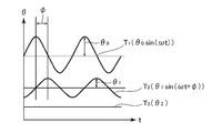
- FIG. 2 is an explanatory diagram showing an example of a temperature wave propagating through the test body in the periodic heating method.
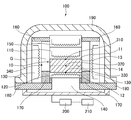
- FIG. 3 is an explanatory diagram showing a main configuration of an example of the present apparatus in a cross-sectional view.
- This method is a method of measuring the thermal diffusivity by a periodic heating method, and propagating a temperature wave from the periodic heating surface 11 of the test body 10 toward the temperature wave absorbing surface 12; Measuring one temperature wave T1; measuring a second temperature wave T2 at a predetermined position 14 inside the test body 10 between the periodic heating surface 11 and the temperature wave absorbing surface 12; Obtaining the thermal diffusivity of the specimen 10 from the amplitude ratio or phase difference between the wave T1 and the second temperature wave T2.
- the apparatus 100 is an apparatus for measuring the thermal diffusivity by a periodic heating method, and in order to propagate a temperature wave from the periodic heating surface 11 of the test body 10 toward the temperature wave absorbing surface 12, the periodic heating is performed.
- Periodic heater 110 disposed opposite to surface 11; disposed to face temperature wave absorption surface 12 in order to maintain the temperature of temperature wave absorption surface 12 of test body 10 at a predetermined constant value.
- a temperature wave is propagated in a one-dimensional direction (a direction indicated by an arrow D shown in FIG. 1) from the periodic heating surface 11 of the test body 10 to be measured on the periodic heating surface 11.
- a temperature wave T1 temperature wave approximated by ⁇ 0 sin ( ⁇ t) shown in FIG. 2
- a second temperature wave T2 ⁇ 1 sin ( ⁇ t + ⁇ shown in FIG. 2 measured at a predetermined position 14 inside the temperature wave T1.
- the temperature T3 of the temperature wave absorption surface 12 opposite to the periodic heating surface 11 of the test body 10 (the surface of the test body 10 opposite to the periodic heating surface 11 in the one-dimensional direction in which the temperature wave propagates) is shown in FIG. As shown in FIG. 2 , it is assumed that the predetermined constant value ⁇ 2 is maintained.
- the periodic heating method a one-dimensional heat flow from the periodic heating surface 11 of the test body 10 to the temperature wave absorption surface 12 is assumed.
- the temperature of the origin (the temperature of the temperature wave absorption surface 12) is maintained at a predetermined constant value
- ⁇ angular frequency [s ⁇ 1 ]
- t time [s]
- ⁇ an arbitrary phase [rad]).
- the 1st temperature wave T1 is given to the periodic heating surface 11 of the test body 10, the 2nd temperature wave T2 reaches
- k is represented by the following formula (III), and i is an imaginary unit.
- ⁇ is an angular frequency represented by the following formula (IV), and ⁇ is a thermal diffusivity [m 2 / s].
- f is the period [s].
- the amplitude ratio A or the phase difference ⁇ obtained by comparing the first temperature wave T1 on the periodic heating surface 11 of the test body 10 and the second temperature wave T2 at the predetermined position 14 inside the test body 10. Based on the above, the thermal diffusivity ⁇ of the specimen 10 is obtained.
- the amplitude ratio A is substituted into the above formula (I) to obtain k, and then the value of k is substituted into the above formula (III), so that the thermal diffusivity ⁇ [m 2 / s] of the specimen 10 is obtained. Is obtained.
- k is obtained by substituting the phase difference ⁇ [rad] into the above formula (II), the value of k is substituted into the above formula (III), and the thermal diffusivity ⁇ [m 2 / s] is obtained.
- the thermal conductivity ⁇ [W / (m ⁇ K)] of the test body 10 is equal to the thermal diffusivity ⁇ [m 2 / s] obtained as described above and the test body 10 measured separately. It is obtained by substituting the density ⁇ [kg / m 3 ] and the specific heat c [J / (kg ⁇ K)] into the following equation (V).
- the present apparatus 100 is preferably used in the present method for measuring the thermal diffusivity of the specimen 10 by the periodic heating method as described above.
- the apparatus 100 includes a periodic heater 110 and a temperature wave absorption heater 120 as shown in FIG.
- the periodic heater 110 heats the periodic heating surface 11 so as to give a temperature wave to the periodic heating surface 11 of the test body 10.
- a DC power supply 200 and a function generator 210 are connected to the periodic heater 110.
- the DC power source 200 supplies a DC current to the periodic heater 110.
- the function generator 210 is a device that sets the period and amplitude of the temperature wave generated by the periodic heater 110.
- the periodic heater 110 generates a temperature wave having a period and amplitude set by the function generator 210 via the DC power supply 200.
- Temperature wave absorption heater 120 adjusts the heating of the temperature wave absorbing surface 12 so that the temperature of the temperature wave absorbing surface 12 of the specimen 10 is maintained at a predetermined constant value theta 2.
- the apparatus 100 keeps the temperature of the side surface 13 of the test body 10 (the surface of the test body 10 connecting the periodic heating surface 11 and the temperature wave absorption surface 12 as shown in FIGS. 1 and 3) within a predetermined range.
- it has the surrounding heater 130 arrange
- the ambient heater 130 adjusts the heating of the side surface 13 so that the temperature of the side surface 13 of the test body 10 is maintained within a predetermined range.
- the arrangement of the surrounding heater 130 is not particularly limited as long as the surrounding heater 130 is arranged to face the side surface 13. However, in the example illustrated in FIG. 3, the surrounding heater 130 is disposed on the side surface 13 through the gap G. Opposed to each other.
- the gap G may be a space filled with gas (for example, air) or a vacuum.
- the surrounding heater 130 may be, for example, a cylindrical heater (for example, a cylindrical heater) surrounding the side surface 13 of the test body 10.
- the periodic heater 110, the temperature wave absorption heater 120, and the surrounding heater 130 are not particularly limited as long as they can heat the periodic heating surface 11, the temperature wave absorption surface 12, and the side surface 13 of the test body 10, respectively. It is a heater, a lamp heater or a laser irradiation device.
- the apparatus 100 includes a first temperature sensor 310, a second temperature sensor 320, and a third temperature sensor 330. As shown in FIGS. 1 and 3, the first temperature sensor 310, the second temperature sensor 320, and the third temperature sensor 330 are preferably arranged linearly in a one-dimensional direction in which a temperature wave is propagated.
- the first temperature sensor 310, the second temperature sensor 320, and the third temperature sensor 330 are preferably arranged on a virtual perpendicular drawn from the periodic heating surface 11 to the temperature wave absorption surface 12, for example. It is good also as arrange
- the temperature wave absorption heater 120 Based on the measurement result of the temperature wave absorption surface 12 by the third temperature sensor 330, the temperature wave absorption heater 120 absorbs the temperature wave absorption so that the temperature of the temperature wave absorption surface 12 is maintained at a predetermined constant value. Adjust the heating of surface 12.
- the apparatus 100 includes a fourth temperature sensor 340 for adjusting the heating by the ambient heater 130.
- the fourth temperature sensor 340 is disposed in contact with the surface of the surrounding heater 130 facing the side surface 13 of the test body 10.
- the ambient heater 130 adjusts the output of the ambient heater 130 (heating by the ambient heater 130) based on the temperature measurement result by the fourth temperature sensor 340.
- the first temperature sensor 310, the second temperature sensor 320, the third temperature sensor 330, and the fourth temperature sensor 340 are, for example, a thermocouple or a platinum resistor.
- the thickness of the first temperature sensor 310, the second temperature sensor 320, the third temperature sensor 330, and the fourth temperature sensor 340 may be, for example, one tenth or less of the thickness d of the test body 10. preferable.
- the thickness of the casing Is a cylindrical case
- the diameter of the case is preferably 1/10 or less of the thickness d of the test body 10.
- the apparatus 100 includes a cooling device 140 disposed on the opposite side of the temperature wave absorption heater 120 from the test body 10.
- the cooling device 140 cools the temperature wave absorption heater 120 so that the temperature wave is efficiently absorbed by the temperature wave absorption surface 12.
- the cooling device 140 is a cooling tank containing a refrigerant, for example.
- the apparatus 100 includes an auxiliary heater 150 disposed on the opposite side to the test body 10 of the periodic heater 110.
- the auxiliary heater 150 keeps the periodic heater 110 warm so as to reduce heat loss from the periodic heater 110.
- the auxiliary heater 150 is, for example, an electric heater.
- the apparatus 100 includes a heat insulating material 160 disposed between the surrounding heater 130 and the auxiliary heater 150. This heat insulating material 160 ensures the thermal stability around the test body 10.
- the apparatus 100 includes a heat insulating material 170 disposed around the cooling device 140. This heat insulating material 170 ensures thermal stability around the test body 10.
- the measurement system described above is disposed on a metal plate 180 (for example, a stainless steel plate) and covered with a casing 190 (for example, a bell jar).
- the test object 10 to be measured is not particularly limited as long as it is arranged between the periodic heater 110 and the temperature wave absorption heater 120.
- the test body 10 may be selected from the group consisting of a heat insulating material, a laminated body of a heat insulating material and another member, plastic, metal, wood, gypsum board, and cement, for example.
- the heat insulating material may be, for example, a fibrous heat insulating material, a porous heat insulating material, or a vacuum heat insulating material.
- the fibrous heat insulating material is selected from the group consisting of, for example, rock wool heat insulating material, glass wool heat insulating material, alumina-based fiber heat insulating material (for example, alumina fiber wool heat insulating material), and alumina-silica-based fiber heat insulating material. Also good.
- the porous heat insulating material is selected from the group consisting of, for example, an inorganic porous heat insulating material (for example, calcium silicate heat insulating material) or a foamed resin heat insulating material (for example, a foamed rubber molded body, a foamed polyurethane molded body, or a polystyrene foam molded body). It is also good to do.
- an inorganic porous heat insulating material for example, calcium silicate heat insulating material
- a foamed resin heat insulating material for example, a foamed rubber molded body, a foamed polyurethane molded body, or a polystyrene foam molded body. It is also good to do.
- the laminated body of a heat insulating material and another member is good also as being a laminated body which has the said heat insulating material and the metal member and / or glass member which were laminated
- the thermal diffusivity of the test specimen 10 exhibiting a relatively low thermal conductivity at a relatively high temperature can be measured with high accuracy. Therefore, for example, the test body 10 may have a thermal conductivity of 0.5 W / (m ⁇ K) or less at 1000 ° C., for example, and a heat of 0.3 W / (m ⁇ K) or less at 1000 ° C. It may have conductivity, or may have thermal conductivity of 0.2 W / (m ⁇ K) or less at 1000 ° C.
- the lower limit value of the thermal conductivity of the test body 10 is not particularly limited.
- the test body 10 may have a thermal conductivity of 0.01 W / (m ⁇ K) or more at 1000 ° C. .
- test body 10 is not particularly limited as long as it is disposed between the periodic heater 110 and the temperature wave absorption heater 120, for example, a flat plate shape is preferable.
- the periodic heating surface 11 and the temperature wave absorption surface 12 are arranged substantially in parallel.
- the test body 10 may be composed of a single test body, or may be composed of two or more homogeneous test bodies stacked in the direction in which the temperature wave propagates. That is, the test body 10 may be, for example, one plate-like heat insulating material or a laminated body formed by laminating two or more same types of plate-like heat insulating materials.
- test body 10 When the test body 10 is formed by stacking two or more test bodies, if a gap is formed between two adjacent test bodies, a gas (air) layer is formed between the two test bodies. The measurement result is affected by the thermal conductivity of the gas, and an error occurs.
- the test body 10 is formed by laminating two or more test bodies, in a pair of the test bodies adjacent in the direction in which the temperature wave propagates, the surface of one test body and the other facing the surface For example, it is preferable not to form a gap of 0.5 mm or more between the surface of the test body.
- a temperature wave is propagated from the periodic heating surface 11 of the test body 10 toward the temperature wave absorption surface 12. That is, a temperature wave having a predetermined period and a predetermined amplitude is generated by the periodic heater 110 facing the periodic heating surface 11. As a result, a temperature wave corresponding to the temperature wave generated by the periodic heater 110 is given to the periodic heating surface 11 of the test body 10.
- the temperature wave given to the periodic heating surface 11 and propagating through the inside of the test body 10 reaches the temperature wave absorption surface 12 without being completely attenuated. That is, the periodic heater 110 gives a temperature wave that reaches the temperature wave absorbing surface 12 of the test body 10 to the periodic heating surface 11 of the test body 10.
- the periodic heater 110 generates a temperature wave whose center of amplitude is a predetermined temperature.
- the temperature at the center of the amplitude is not particularly limited.
- the temperature may be a predetermined temperature within a range of ⁇ 190 ° C. to 1500 ° C., or may be a predetermined temperature within a range of 25 ° C. to 1500 ° C.
- the temperature may be a predetermined temperature within a range of 700 ° C. to 1500 ° C., or may be a predetermined temperature within a range of 800 ° C. to 1500 ° C.
- the thermal diffusivity of the specimen 10 can be measured with high accuracy even at such a relatively high temperature (for example, 700 ° C. to 1500 ° C. or 800 ° C. to 1500 ° C.).
- the arithmetic average value of the center temperature of the amplitude of the temperature wave on the periodic heating surface 11 and the predetermined constant temperature on the temperature wave absorption surface 12 Is measured under such conditions that the temperature becomes 1000 ° C.
- the gas around the test body 10 (the gas in contact with the side surface 13 of the test body 10 (the gas filled in the gap G)) is in contact with the gas.
- the temperature of other members such as the surrounding heater 130 and the heat insulating materials 160 and 170 arranged to prevent heat loss periodically changes to form another temperature wave.
- this other temperature wave penetrates into the inside of the test body 10 from the side surface 13 of the test body 10 and overlaps with the original temperature wave propagating from the periodic heating surface 11 toward the temperature wave absorption surface 12, and is measured. An error occurs.
- the amplitude of the temperature wave generated by the periodic heater 110 is preferably a predetermined value within a range of 1 ° C. to 10 ° C., for example, and is preferably a predetermined value within a range of 1 ° C. to 5 ° C. More preferably, the predetermined value is in the range of 2 ° C. to 4 ° C.
- the temperature wave generated by the periodic heater 110 preferably changes within a range of a predetermined temperature ⁇ 10 ° C., for example, preferably changes within a range of a predetermined temperature ⁇ 5 ° C., and the predetermined temperature ⁇ 2 ° C. It is preferable to change within the range.
- the temperature wave can be properly propagated to the test body 10 and the measurement accuracy can be improved.
- the temperature wave is periodically within a range of 1000 ⁇ 5 ° C. (995 ° C. to 1005 ° C.). Change.
- the temperature of the test body 10 changes almost uniformly at all positions in the direction in which the temperature wave propagates in the test body 10, and the inside of the test body 10 Thus, a state in which the temperature wave propagates cannot be formed, and a measurement error occurs.
- the period of the temperature wave is too short, while the temperature wave propagates through the inside of the test body 10, the temperature wave is completely attenuated and disappears on the way, resulting in a measurement error.
- the period of the temperature wave generated by the periodic heater 110 is preferably a predetermined value within a range of 1 minute to 120 minutes, for example, and is preferably a predetermined value within a range of 15 minutes to 100 minutes. More preferably, the predetermined value is within a range of 30 minutes to 60 minutes.
- the period of the temperature wave is within the appropriate range, the temperature wave can be appropriately propagated to the test body 10 and the measurement accuracy can be increased.
- the temperature wave is distorted.
- the amplitude ratio or phase difference between the first temperature wave T1 and the second temperature wave T2 at the predetermined position 14 inside the test body 10 cannot be measured accurately, resulting in a measurement error.
- a temperature wave for one cycle each.
- the difference between the average value of the center temperature of the amplitude and the average value of the center temperature of the amplitude of the temperature wave for the three cycles is preferably within ⁇ 2 ° C, more preferably within ⁇ 1 ° C. It is particularly preferable that the temperature is within ⁇ 0.2 ° C.
- the average value of the center temperature of the amplitude of the temperature wave for each one cycle, the average value of the center temperature of the amplitude for the three cycles is preferably within ⁇ 2%, more preferably within ⁇ 0.5%, and particularly preferably within ⁇ 0.2%.
- the temperature of the temperature wave absorption surface 12 is set to a predetermined constant value. Adjust.
- the heating of the temperature wave absorption surface 12 by the temperature wave absorption heater 120 is adjusted so that the temperature of the temperature wave absorption surface 12 becomes a predetermined constant value.
- the temperature wave absorption heater 120 adjusts the heating of the temperature wave absorption surface 12 based on the temperature measurement result of the temperature wave absorption surface 12 by the third temperature sensor 330.
- the temperature wave absorption heater 120 increases its output to increase the heating of the temperature wave absorption surface 12 and absorb the temperature wave absorption. Increase the temperature of the surface 12.
- the temperature wave absorption heater 120 decreases the output to weaken the heating of the temperature wave absorption surface 12, and the temperature wave absorption surface 12. Reduce the temperature.
- weakening the heating of the temperature wave absorption surface 12 it is good also as operating the cooling device 140 mentioned above and cooling the temperature wave absorption heater 120.
- the predetermined constant value at which the temperature of the temperature wave absorption surface 12 is to be adjusted is, for example, a temperature lower or higher than the central temperature of the amplitude of the temperature wave on the periodic heating surface 11 by a predetermined value in the range of 0 ° C. to 20 °
- the temperature may be lower or higher than the center temperature of the amplitude by a predetermined value within a range of 0 ° C. to 10 ° C., and may be 0 ° C. to 5 ° C. from the center temperature of the amplitude.
- the temperature may be lower or higher by a predetermined value within the range.
- the predetermined constant value to which the temperature of the temperature wave absorption surface 12 should be adjusted may be, for example, a predetermined constant value within the range of the center temperature ⁇ 20 ° C. of the temperature wave amplitude on the periodic heating surface 11.
- it may be a predetermined constant value within the range of the center temperature ⁇ 10 ° C., or may be a predetermined constant value within the range of the center temperature ⁇ 5 ° C.
- the thermal diffusivity ⁇ is obtained using the above formulas (I) to (III).
- This measurement principle is based on the condition that the temperature of one surface (periodic heating surface 11) of the test body 10 is periodically changed and the temperature of the opposite surface (temperature wave absorption surface 12) is kept constant.
- the solution obtained by solving the conduction equation is used, in practice, it is impossible to make the temperature of the temperature wave absorbing surface 12 completely constant. For this reason, the degree to which the temperature fluctuation on the temperature wave absorption surface 12 can be suppressed greatly affects the measurement accuracy.
- the temperature of the temperature wave absorbing surface 12 is preferably maintained within a predetermined constant value ⁇ 0.5 ° C., and more preferably maintained within a predetermined constant value ⁇ 0.2 ° C. It is particularly preferable to maintain within a range of a predetermined constant value ⁇ 0.05 ° C.
- the temperature wave propagated from the periodic heating surface 11 is not efficiently absorbed by the temperature wave absorption surface 12 (disappearance). Measurement error may occur.
- the temperature wave absorption surface 12 and the temperature wave absorption heater 120 may be brought into contact with each other.
- the 3rd temperature sensor 330 for measuring the temperature of the temperature wave absorption surface 12 is good also as arrange
- the third temperature sensor 330 may be arranged without contacting the temperature wave absorption heater 120.
- the temperature of the side surface 13 of the test body 10 is set within a predetermined range. Adjust.
- the heating of the side surface 13 by the surrounding heater 130 is adjusted so that the temperature of the side surface 13 of the test body 10 is within a predetermined range.
- the ambient heater 130 adjusts the heating of the side surface 13 of the test body 10 based on the result of the temperature measured by the fourth sensor 340.
- the ambient heater 130 increases its output to increase the heating of the side surface 13 and increase the temperature of the side surface 13. In addition, when the measured temperature exceeds the predetermined range, the ambient heater 130 decreases the output to weaken the heating of the side surface 13 and decrease the temperature of the side surface 13.
- the predetermined range in which the temperature of the side surface 13 of the test body 10 should be adjusted is, for example, the arithmetic average value ⁇ 50 ° C. between the center temperature of the temperature wave amplitude on the periodic heating surface 11 and the predetermined constant temperature on the temperature wave absorption surface 12.
- the arithmetic average value ⁇ 20 ° C. is more preferable, and the arithmetic average value ⁇ 5 ° C. is particularly preferable.
- the temperature may be adjusted to be within a predetermined range.
- the temperature of the surrounding heater 130 is maintained within a predetermined range, that is, a predetermined constant value and the vicinity thereof.
- the fourth temperature sensor 340 is arranged on the surface of the surrounding heater 340 facing the side surface 13 of the test body 10, and based on the temperature measurement result by the fourth temperature sensor 340.
- the output of the surrounding heater 130 (heating by the surrounding heater 130) is adjusted so that the measured temperature is within a predetermined range.
- the predetermined range in which the temperature of the surrounding heater 130 should be adjusted is, for example, a range of ⁇ 50 ° C. arithmetic average value between the center temperature of the temperature wave amplitude on the periodic heating surface 11 and the predetermined constant temperature on the temperature wave absorption surface 12.
- the arithmetic average value is more preferably within a range of ⁇ 20 ° C., and the arithmetic average value is preferably within a range of ⁇ 5 ° C.
- a first temperature wave T1 on the periodic heating surface 11 of the test body 10 and a second temperature wave T2 at a predetermined position 14 inside the test body 10 are measured. That is, the temperature wave T ⁇ b> 1 applied from the periodic heater 110 to the periodic heating surface 11 is measured by the first temperature sensor 310 and transmitted from the periodic heating surface 11 to the predetermined position 14 inside the test body 10. The temperature wave T ⁇ b> 2 is measured by the second temperature sensor 320.
- one of the characteristic features of this embodiment is that, in this method, each of the measured first temperature wave T1 and second temperature wave T2 for one period is approximated to a trigonometric function by the least square method.
- the thermal diffusivity of the specimen 10 is measured from the amplitude ratio or phase difference between the first temperature wave T1 and the second temperature wave T2 approximated to a trigonometric function.
- the temperature wave is treated as being represented by a trigonometric function, but the actually measured temperature wave is not represented by a complete trigonometric function. For this reason, when the waveform of the actually measured temperature wave is distorted, the amplitude ratio or the phase difference cannot be obtained accurately, resulting in a measurement error.
- the amplitude ratio is determined by a ratio between the amplitude of the first temperature wave T1 on the periodic heating surface 11 and the amplitude of the second temperature wave T2 at the predetermined position 14 inside the test body 10.
- the phase difference is determined by the time until the first temperature wave T1 on the periodic heating surface 11 reaches the predetermined position 14 inside the test body 10, and is measured as a base point for measuring the time. The time corresponding to the peak of the first temperature wave T1 and the peak of the second temperature wave T2 is used.
- the base point for obtaining the amplitude ratio or phase difference, for example, the peak point of the temperature wave cannot be obtained accurately, resulting in a measurement error.
- the temperature wave is attenuated violently. Will disturb the waveform of the temperature wave propagating. For example, when the temperature wave is drifting (when the center temperature of the amplitude of the temperature wave increases or decreases with time), the waveform of the measured temperature wave is distorted.
- the peak position of the temperature wave can be appropriately specified, and as a result, the amplitude The ratio and phase difference can be accurately determined.
- the temperature wave on the periodic heating surface 11 of the test body 10 is represented by ⁇ h0 sin ( ⁇ t), and the temperature ⁇ inside the test body 10 changes as shown in the following formula (VI). Assume.
- ⁇ is a phase difference between the temperature wave on the periodic heating surface 11 and the temperature wave inside the test body 10, and ⁇ 1 and ⁇ 2 are expressed by the following formula (VIII).
- the temperature ⁇ with respect to time t is measured, and the phase difference ⁇ is determined from the data for one period of the temperature wave using the least square method.
- the angular frequency ⁇ is known from the above formula (IV).
- a characteristic point of the temperature wave for example, the time or temperature of the peak of the waveform is used to determine the amplitude ratio or phase difference between the temperature wave on the periodic heating surface 11 and the temperature wave inside the test body 10. Is completely different.
- the characteristic point When only the characteristic point of the temperature wave is used, the characteristic point must be specified from the data. For example, when the waveform is distorted, it is difficult to specify the characteristic point. Become.
- the amplitude of the temperature wave in the test body 10 is small and is in contact with the temperature around the test body 10 (for example, the side surface 13 of the test body 10).
- a slight change in the temperature of the gas G) may distort the waveform of the temperature wave. In such a case, it is difficult to specify a characteristic point of the temperature wave, and if approximation is performed using only the characteristic point, a measurement error occurs.
- the amplitude of the temperature wave on the periodic heating surface 11 is too large, a temperature wave far from the trigonometric function is generated. That is, in this case, the portion of the temperature wave where the temperature rises draws a curve that is close to a trigonometric function, but the portion of the temperature drop that falls is not able to catch up with the curve of the trigonometric function. As a whole, the waveform may be distorted.
- the amplitude of the temperature wave can be determined according to the heat capacity and thermal diffusivity of the test body 20. That is, the amplitude of the temperature wave given to the periodic heating surface 11 is determined using the following method.
- the temperature wave ⁇ generated on the periodic heating surface 11 is represented by the following formula (IX).
- the amplitude ⁇ 0 of the temperature wave applied to the periodic heating surface 11 can be determined by the above formula (XII).
- the amplitude obtained by the above formula (XII) is a guideline and is not a strict value, but it is preferable to determine the amplitude ⁇ 0 based on the following formula (XIII).
- the average value of the center temperature of the amplitude of the temperature wave for one period and the amplitude of the temperature wave for the three periods is preferably within ⁇ 2 ° C., more preferably within ⁇ 1 ° C., and particularly preferably within ⁇ 0.5 ° C.
- the amplitude of the temperature wave for the three periods of the average value of the central temperature of the amplitude of the temperature wave for each one period is preferably within ⁇ 2%, more preferably within ⁇ 1%, and particularly preferably within ⁇ 0.5%.
- the amplitude ratio or the phase difference can be obtained more accurately.
- a predetermined temperature wave was generated by the periodic heater 110, and the temperature wave was measured on the periodic heating surface 11 of the test body 10.
- the measured temperature wave for one period was approximated to a trigonometric function by the least square method.
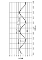
- FIG. 4 shows the actually measured temperature wave data by a thin line, and the result obtained by approximating the temperature wave for one period to a trigonometric function by the least square method is shown by a thick line.
- the measured temperature wave can be appropriately approximated to a trigonometric function by using the measured data for one period and using the least square method.
- the thermal diffusivity of the test specimen 10 was measured by this method using the apparatus 100 as shown in FIG. 3, and the thermal conductivity of the test specimen 10 was obtained from the thermal diffusivity.
- the temperature wave for one period measured at the periodic heating surface 11 and the predetermined position 14 inside the test body 10 is approximated to a trigonometric function by the least square method, and the peak position of the temperature wave is specified.
- the phase difference of the temperature wave was determined based on the identified peak, and the thermal diffusivity of the test body 10 was determined from the phase difference.
- thermocouples were used as the periodic heater 110, the temperature wave absorption heater 120, and the ambient heater 130.
- the ambient heater 130 was used with its output limited in advance to a range of a predetermined value ⁇ 0.05%.
- thermocouples were used as the first temperature sensor 310, the second temperature sensor 320, the third temperature sensor 330, and the fourth temperature sensor 340.
- a groove is formed in the periodic heating surface 11 and the first temperature sensor 310 is arranged in the groove, and between the periodic heating surface 11 and the periodic heater 110 (the first heater). Between the temperature sensor 310 and the periodical heater 110), an inorganic fiber fleece was disposed.
- two alumina plates are arranged with a gap between the temperature wave absorbing surface 12 and the temperature wave absorbing heater 120, and the two sandwiched between the two alumina plates.
- a third temperature sensor 330 is disposed in the gap.
- an alumina-silica fiber heat insulating material 150 mm ⁇ 100 mm, thickness 30 mm was used as the test body 10, and the test body 10 was tested at 100 ° C., 200 ° C., 400 ° C., 600 ° C., 800 ° C., 1000
- the thermal diffusivity was measured at 1,200, 1,400, and 1500 ° C., and the thermal conductivity was determined from the thermal diffusivity.
- the amplitude of the temperature wave generated by the periodic heater 110 was 3 ° C., and the period was 60 minutes.
- the temperature of the temperature wave absorbing surface 12 of the test body 10 was maintained within a range of a predetermined value ⁇ 0.05 ° C.
- the average value of the center temperature of the amplitude of the temperature wave for one period and the average of the center temperature of the amplitude of the temperature wave for the three periods was within ⁇ 2 ° C.
- the thermal conductivity of the specimen 10 was also measured by the GHP method.
- test body 10 two fiber reinforced cement plates (150 mm ⁇ 100 mm, thickness 20 mm) are used as the test body 10, the thermal diffusivities of the test body 10 at 100 ° C., 300 ° C., and 500 ° C. are measured, and the thermal diffusivity is measured. From this, the thermal conductivity was determined.
- the amplitude of the temperature wave generated by the periodic heater 110 was 2 ° C., and the period was 60 minutes.
- the temperature of the temperature wave absorbing surface 12 of the test body 10 was maintained within a range of a predetermined value ⁇ 0.05 ° C.
- the average value of the center temperature of the amplitude of the temperature wave for one period and the average of the center temperature of the amplitude of the temperature wave for the three periods was within ⁇ 2 ° C.
- the thermal conductivity of the specimen 10 was also measured by the GHP method.
- FIG. 5 and FIG. 6 show the results of measuring the thermal conductivity of the alumina-silica fiber heat insulating material and the dense porous body by the periodic heating method, respectively.
- the horizontal axis indicates the temperature (° C.) at which the thermal conductivity is measured (the arithmetic average value of the center temperature of the temperature wave amplitude on the periodic heating surface 11 and the predetermined constant temperature on the temperature wave absorption surface 12.
- the vertical axis indicates the thermal conductivity (W / (m ⁇ K)) measured at each temperature.
- circles indicate the results measured by this method using the periodic heating method
- squares indicate the results measured by the GHP method.
- the measurement result by this method using the present apparatus 100 almost coincided with the measurement result by the GHP method. That is, according to the method using the apparatus 100, it was confirmed that the thermal diffusivity and the thermal conductivity can be measured with high accuracy in a wide temperature range.
Landscapes
- Physics & Mathematics (AREA)
- Health & Medical Sciences (AREA)
- Life Sciences & Earth Sciences (AREA)
- Chemical & Material Sciences (AREA)
- Analytical Chemistry (AREA)
- Biochemistry (AREA)
- General Health & Medical Sciences (AREA)
- General Physics & Mathematics (AREA)
- Immunology (AREA)
- Pathology (AREA)
- Investigating Or Analyzing Materials Using Thermal Means (AREA)
Abstract
高い精度で熱拡散率を測定することができる方法及び装置を提供する。本発明に係る周期加熱法により熱拡散率を測定する方法は、試験体(10)の周期加熱面(11)から温度波吸収面(12)に向けて温度波を伝播させること;前記周期加熱面における第一温度波を測定すること;前記周期加熱面と前記温度波吸収面との間の前記試験体の内部の所定位置(14)における第二温度波を測定すること;前記第一温度波と前記第二温度波との振幅比又は位相差から前記試験体の熱拡散率を得ること;を含み、測定された一周期分の前記第一温度波及び前記第二温度波の各々を最小二乗法により三角関数に近似し、三角関数に近似された前記第一温度波と前記第二温度波との前記振幅比又は前記位相差から前記試験体の熱拡散率を測定する。
Description
本発明は、熱拡散率を測定する方法に関し、特に、周期加熱法により熱拡散率を測定する方法及び装置に関する。
試験体の熱伝導率を測定するための方法としては、定常法である保護熱板(Guarded Hot Plate:GHP)法や熱流計法の他に、非定常法である周期加熱法がある。
周期加熱法においては、試験体の表面から内部に、一次元方向に温度波を伝播させ、当該表面で測定される温度波と、当該内部で測定される温度波と、の振幅比又は位相差から、当該試験体の熱拡散率を求め、さらに、当該熱拡散率と、別途測定された当該試験体の密度及び比熱とから当該試験体の熱伝導率を求める(特許文献1、特許文献2、非特許文献1、非特許文献2参照)。
大村高弘;熱物性, 21(2), 2007, 86-96
大村高弘、坪井幹憲;熱物性, 13(4), 1999, 264-270
しかしながら、従来の周期加熱法においては、十分に高い精度で熱拡散率を測定することが難しかった。
すなわち、従来、例えば、測定された温度波のピークの位置を適切に特定できないことにより、振幅比又は位相差を正確に求めることができず、その結果、高い精度で熱拡散率を測定することができないことがあった。
本発明は、上記課題に鑑みて為されたものであって、高い精度で熱拡散率を測定することができる方法を提供することをその目的の一つとする。
上記課題を解決するための本発明の一実施形態に係る方法は、周期加熱法により熱拡散率を測定する方法であって、試験体の周期加熱面から温度波吸収面に向けて温度波を伝播させること;前記周期加熱面における第一温度波を測定すること;前記周期加熱面と前記温度波吸収面との間の前記試験体の内部の所定位置における第二温度波を測定すること;前記第一温度波と前記第二温度波との振幅比又は位相差から前記試験体の熱拡散率を得ること;を含み、測定された一周期分の前記第一温度波及び前記第二温度波の各々を最小二乗法により三角関数に近似し、三角関数に近似された前記第一温度波と前記第二温度波との前記振幅比又は前記位相差から前記試験体の熱拡散率を測定することを特徴とする。本発明によれば、高い精度で熱拡散率を測定する方法を提供することができる。
また、前記方法において、前記試験体を伝播する、連続する3周期分の前記温度波において、各1周期分の前記温度波の振幅の中心温度の平均値と、前記3周期分の前記温度波の振幅の中心温度の平均値との差分が、±2℃以内であることとしてもよい。また、前記方法において、前記試験体を伝播する、連続する3周期分の前記温度波において、各1周期分の前記温度波の振幅の中心温度の平均値の、前記3周期分の前記温度波の振幅の中心温度の平均値に対する変化率が、±2%以内であることとしてもよい。
本発明によれば、高い精度で熱拡散率を測定する方法を提供することができる。
以下に、本発明の一実施形態について説明する。なお、本発明は、本実施形態に限られるものではない。
まず、本実施形態に係る熱拡散率測定方法(本方法)及び熱拡散率測定装置(本装置)の概要について説明する。図1は、周期加熱法により試験体の熱拡散率を測定する原理を示す説明図である。図2は、周期加熱法において試験体を伝播する温度波の一例を示す説明図である。図3は、本装置の一例の主な構成を断面視で示す説明図である。
本方法は、周期加熱法により熱拡散率を測定する方法であって、試験体10の周期加熱面11から温度波吸収面12に向けて温度波を伝播させること;当該周期加熱面11における第一温度波T1を測定すること;当該周期加熱面11と当該温度波吸収面12との間の当該試験体10の内部の所定位置14における第二温度波T2を測定すること;当該第一温度波T1と当該第二温度波T2との振幅比又は位相差から当該試験体10の熱拡散率を得ること;を含む。
本装置100は、周期加熱法により熱拡散率を測定するための装置であって、試験体10の周期加熱面11から温度波吸収面12に向けて温度波を伝播させるために、当該周期加熱面11に対向して配置される周期加熱ヒータ110;当該試験体10の当該温度波吸収面12の温度を所定の一定値に維持するために、当該温度波吸収面12に対向して配置される温度波吸収ヒータ120;当該周期加熱面11における第一温度波T1を測定するための第一温度センサ310;当該周期加熱面11と当該温度波吸収面12との間の当該試験体10の内部の所定位置14における第二温度波T2を測定するための第二温度センサ320;当該温度波吸収面12の温度を測定するための第三温度センサ330;を有する。
ここで、周期加熱法について説明する。周期加熱法においては、試験体10の周期加熱面11から内部に、一次元方向(図1に示す矢印Dの指す方向)に温度波を伝播させ、当該周期加熱面11で測定される第一温度波T1(図2に示すθ0sin(ωt)で近似される温度波)と、当該内部の所定の位置14で測定される第二温度波T2(図2に示すθ1sin(ωt+φ)で近似される温度波)との振幅比A(=θ1/θ0:振幅の減衰率を示す比率)又は位相差φから、当該試験体10の熱拡散率を求める。なお、試験体10の内部を伝播する温度波は、次第に減衰するため、第二温度波T2の振幅θ1は、第一温度波T1の振幅θ0より小さい。
また、試験体10の周期加熱面11と反対側の温度波吸収面12(温度波が伝播する一次元方向における周期加熱面11と反対側の試験体10の表面)の温度T3は、図2に示すように、所定の一定値θ2に維持されていると仮定する。
すなわち、周期加熱法においては、試験体10の周期加熱面11から温度波吸収面12への一次元方向の熱流を仮定する。具体的に、例えば、図1に示すように、この一次元方向(矢印Dの指す方向)にx軸を設定し、試験体10の厚さ(周期加熱面11と温度波吸収面12との距離)がdであるとすると,当該x軸の原点(x=0)の位置に当該試験体10の温度波吸収面12が配置され、x=dの位置に当該試験体10の周期加熱面11が配置される。
ここで、原点の温度(温度波吸収面12の温度)は所定の一定値に維持され、x=dの位置の温度(周期加熱面11の温度)は、sin(ωt+η)で表される周期(ωは角振動数[s-1]、tは時間[s]、ηは任意の位相[rad]である。)で変化していると仮定する。
そして、上述のとおり、試験体10の周期加熱面11に第一温度波T1が与えられ、当該試験体10の内部の所定位置14に第二温度波T2が到達し、当該試験体10の温度波吸収面12の温度は所定の一定値θ2に維持されるという条件の下で一次元の熱伝導方程式を解くと、x=dの位置(周期加熱面11)で測定される第一温度波T1と、任意の位置x=xm(d>xm>0)(例えば、試験体10の内部の所定位置14)で測定される第二温度波T2と、の振幅比A(=θ1/θ0)(θ0は第一温度波T1の振幅であり、θ1は第二温度波T2の振幅である。)及び位相差φは、それぞれ下記の式(I)及び式(II)により求められる。


上記式(I)、(II)において、kは下記の式(III)で表され、iは虚数単位である。また、下記式(III)において、ωは、下記の式(IV)で表される角振動数であり、κは熱拡散率[m2/s]である。また、下記式(IV)において、fは周期[s]である。


こうして、試験体10の周期加熱面11における第一温度波T1と、当該試験体10の内部の所定位置14における第二温度波T2とを比較することにより得られた振幅比A又は位相差φに基づき、当該試験体10の熱拡散率κが求められる。
すなわち、まず振幅比Aを上記式(I)に代入してkを求め、次いで当該kの値を上記式(III)に代入して、試験体10の熱拡散率κ[m2/s]が得られる。同様に、位相差φ[rad]を上記式(II)に代入してkを求め、当該kの値を上記式(III)に代入して、試験体10の熱拡散率κ[m2/s]が得られる。
さらに、試験体10の熱伝導率λ[W/(m・K)]は,上述のようにして得られた熱拡散率κ[m2/s]と、別途測定された当該試験体10の密度ρ[kg/m3]及び比熱c[J/(kg・K)]とを下記の式(V)に代入することにより求められる。

本装置100は、上述のような周期加熱法により試験体10の熱拡散率を測定する本方法において好ましく使用される。本装置100は、図3に示すように、周期加熱ヒータ110及び温度波吸収ヒータ120を有している。周期加熱ヒータ110は、試験体10の周期加熱面11に温度波を与えるよう当該周期加熱面11を加熱する。
図3に示す例において、周期加熱ヒータ110には、直流電源200と、ファンクションジェネレーター210とが接続されている。直流電源200は、周期加熱ヒータ110に直流電流を供給する。ファンクションジェネレーター210は、周期加熱ヒータ110が発生させる温度波の周期及び振幅を設定する装置である。周期加熱ヒータ110は、ファンクションジェネレーター210によって設定された周期及び振幅を有する温度波を、直流電源200を介して発生させる。
温度波吸収ヒータ120は、試験体10の温度波吸収面12の温度が所定の一定値θ2に維持されるよう当該温度波吸収面12の加熱を調節する。
また、本装置100は、試験体10の側面13(図1及び図3に示すように、周期加熱面11と温度波吸収面12とをつなぐ試験体10の表面)の温度を所定範囲内に維持するために、当該側面13に対向して配置される周囲ヒータ130を有している。周囲ヒータ130は、試験体10の側面13の温度が所定範囲内に維持されるよう当該側面13の加熱を調節する。
周囲ヒータ130の配置は、当該周囲ヒータ130が側面13に対向して配置されれば特に限られないが、図3に示す例において、当該周囲ヒータ130は、隙間Gを介して当該側面13に対向して配置されている。この隙間Gは、気体(例えば、空気)が充填された空間であることとしてもよいし、真空であることとしてもよい。周囲ヒータ130の形状は特に限られないが、当該周囲ヒータ130は、例えば、試験体10の側面13を囲む筒状のヒータ(例えば、円筒ヒータ)であることとしてもよい。
周期加熱ヒータ110、温度波吸収ヒータ120及び周囲ヒータ130は、それぞれ試験体10の周期加熱面11、温度波吸収面12及び側面13を加熱できるヒータであれば特に限られないが、例えば、電熱ヒータ、ランプヒータ又はレーザー照射装置である。
また、本装置100は、第一温度センサ310、第二温度センサ320及び第三温度センサ330を有している。第一温度センサ310、第二温度センサ320及び第三温度センサ330は、図1及び図3に示すように、温度波が伝播される一次元方向において直線的に配置されることが好ましい。
すなわち、第一温度センサ310、第二温度センサ320及び第三温度センサ330は、例えば、周期加熱面11から温度波吸収面12に引いた仮想的な垂線上に配置されることが好ましく、当該垂線を中心とする半径5mm以下の当該周期加熱面11に平行な仮想的な円内に配置されることとしてもよい。
温度波吸収ヒータ120は、第三温度センサ330による温度波吸収面12の温度の測定結果に基づいて、当該温度波吸収面12の温度が所定の一定値に維持されるよう、当該温度波吸収面12の加熱を調節する。
また、図3に示す例において、本装置100は、周囲ヒータ130による加熱を調節するための第四温度センサ340を有している。この例において、第四温度センサ340は、試験体10の側面13に対向する、周囲ヒータ130の表面と接触して配置されている。周囲ヒータ130は、第四温度センサ340による温度の測定結果に基づいて、当該周囲ヒータ130の出力(当該周囲ヒータ130による加熱)を調節する。
第一温度センサ310、第二温度センサ320、第三温度センサ330及び第四温度センサ340は、例えば、熱電対又は白金抵抗体である。
なお、第一温度センサ310、第二温度センサ320、第三温度センサ330及び第四温度センサ340の厚さが、試験体10の厚さに比べて無視できないくらい大きい場合には、当該温度センサを介した熱損失によって温度波が歪み、測定の誤差が生じる。このため、第一温度センサ310、第二温度センサ320、第三温度センサ330及び第四温度センサ340の厚さは、例えば、試験体10の厚さdの10分の1以下であることが好ましい。
すなわち、例えば、第一温度センサ310、第二温度センサ320、第三温度センサ330及び第四温度センサ340が、筐体を有する熱電対である場合には、当該筐体の厚さ(熱電対が円筒状の筐体を有する場合には、当該筐体の直径)が試験体10の厚さdの10分の1以下であることが好ましい。
また、図3に示す例において、本装置100は、温度波吸収ヒータ120の試験体10と反対側に配置された冷却装置140を有する。冷却装置140は、温度波が温度波吸収面12に効率よく吸収されるように、温度波吸収ヒータ120を冷却する。冷却装置140は、例えば、冷媒を含む冷却タンクである。
また、図3に示す例において、本装置100は、周期加熱ヒータ110の試験体10と反対側に配置された補助ヒータ150を有する。補助ヒータ150は、周期加熱ヒータ110からの熱損失を低減させるよう当該周期加熱ヒータ110を保温する。補助ヒータ150は、例えば、電熱ヒータである。
また、図3に示す例において、本装置100は、周囲ヒータ130と補助ヒータ150との間に配置された断熱材160を有する。この断熱材160は、試験体10の周囲の熱的安定性を確保する。また、図3に示す例において、本装置100は、冷却装置140の周囲に配置された断熱材170を有する。この断熱材170は、試験体10の周囲の熱的安定性を確保する。また、図3に示す例においては、上述した測定系が金属板180(例えば、ステンレス板)の上に配置されるとともに、筐体190(例えば、ベルジャー)により覆われている。
測定の対象となる試験体10は、周期加熱ヒータ110と温度波吸収ヒータ120との間に配置されるものであれば特に限られない。具体的に、試験体10は、例えば、断熱材、断熱材と他の部材との積層体、プラスチック、金属、木材、石膏ボード及びセメントからなる群より選択されることとしてもよい。より具体的に、断熱材は、例えば、繊維質断熱材、多孔質断熱材又は真空断熱材であることとしてもよい。
繊維質断熱材は、例えば、ロックウール断熱材、グラスウール断熱材、アルミナ系繊維質断熱材(例えば、アルミナファイバーウール断熱材)、及びアルミナシリカ系繊維質断熱材からなる群より選択されることとしてもよい。
多孔質断熱材は、例えば、無機多孔質断熱材(例えば、ケイ酸カルシウム断熱材)又は発泡樹脂断熱材(例えば、発泡ゴム成形体、発泡ポリウレタン成形体又は発泡スチロール成形体)からなる群より選択されることとしてもよい。
断熱材と他の部材との積層体は、例えば、当該断熱材と、当該断熱材に積層された金属部材及び/又はガラス部材とを有する積層体であることとしてもよい。
また、本方法においては、後述のとおり、比較的高い温度(例えば、800℃以上)で比較的低い熱伝導率を示す試験体10の熱拡散率を高い精度で測定することができる。そこで、例えば、試験体10は、例えば、1000℃において0.5W/(m・K)以下の熱伝導率を有することとしてもよく、1000℃において0.3W/(m・K)以下の熱伝導率を有することとしてもよく、1000℃において0.2W/(m・K)以下の熱伝導率を有することとしてもよい。なお、試験体10の熱伝導率の下限値は特に限られないが、例えば、当該試験体10は、1000℃において0.01W/(m・K)以上の熱伝導率を有することとしてもよい。
試験体10の形状は、周期加熱ヒータ110と温度波吸収ヒータ120との間に配置されるものであれば特に限られないが、例えば、平板状であることが好ましい。試験体10が平板状である場合には、周期加熱面11と温度波吸収面12とは略平行に配置される。
試験体10は、1つの試験体からなることとしてもよいし、温度波が伝播する方向に積層された2つ以上の同質の試験体からなることとしてもよい。すなわち、試験体10は、例えば、1つの板状断熱材であることとしてもよいし、2つ以上の同一種類の板状断熱材が積層してなる積層体であることとしてもよい。
試験体10が2つ以上の試験体を積層してなる場合、隣接する2つの試験体の間に隙間が形成されると、当該2つの試験体の間に気体(空気)の層が形成され、測定結果が気体の熱伝導率の影響を受け、誤差が生じる。
このため、試験体10が2つ以上の試験体を積層してなる場合、温度波が伝播する方向に隣接する一対の当該試験体において、一方の試験体の表面と、当該表面に対向する他方の試験体の表面との間には、例えば、0.5mm以上の隙間を形成しないことが好ましい。
そして、本方法においては、まず、試験体10の周期加熱面11から温度波吸収面12に向けて温度波を伝播させる。すなわち、周期加熱面11に対向する周期加熱ヒータ110によって、所定の周期及び所定の振幅を有する温度波を発生させる。その結果、試験体10の周期加熱面11には、周期加熱ヒータ110が発生させた温度波に対応する温度波が与えられる。
本方法において、周期加熱面11に与えられ、試験体10の内部を伝播する温度波は、完全に減衰することはなく、温度波吸収面12に到達する。すなわち、周期加熱ヒータ110は、試験体10の温度波吸収面12に到達する温度波を、当該試験体10の周期加熱面11に与える。
また、周期加熱ヒータ110は、振幅の中心が所定温度である温度波を発生させる。振幅の中心の温度は、特に限られないが、例えば、-190℃~1500℃の範囲内の所定温度であることとしてもよく、25℃~1500℃の範囲内の所定温度であることとしてもよく、700℃~1500℃の範囲内の所定温度であることとしてもよく、800℃~1500℃の範囲内の所定温度であることとしてもよい。本方法においては、このような比較的高い温度(例えば、700℃~1500℃又は800℃~1500℃)においても、試験体10の熱拡散率を高い精度で測定することができる。
なお、例えば、試験体10の1000℃における熱拡散率を測定する場合には、周期加熱面11における温度波の振幅の中心温度と、温度波吸収面12における所定の一定温度との算術平均値が1000℃となるような条件で測定を行う。
また、温度波の振幅が大きすぎる場合には、例えば、試験体10の周囲の気体(試験体10の側面13と接している気体(隙間Gに充填されている気体))、当該気体と接している周囲ヒータ130、熱損失を防ぐために配置されている断熱材160,170等の他の部材の温度が周期的に変化して別の温度波が形成されてしまう。
そして、この別の温度波が試験体10の側面13から当該試験体10の内部へ侵入し、周期加熱面11から温度波吸収面12に向けて伝播している本来の温度波と重なり、測定誤差が生じる。
このため、周期加熱ヒータ110で発生させる温度波の振幅は、例えば、1℃~10℃の範囲内の所定値であることが好ましく、1℃~5℃の範囲内の所定値であることがより好ましく、2℃~4℃の範囲内の所定値であることが特に好ましい。
また、周期加熱ヒータ110で発生させる温度波は、例えば、所定温度±10℃の範囲内で変化することが好ましく、所定温度±5℃の範囲内で変化することが好ましく、所定温度±2℃の範囲内で変化することが好ましい。
温度波の振幅が上記の適切な範囲内であることにより、試験体10に温度波を適切に伝播させることができ、測定精度を高めることができる。なお、例えば、温度波の振幅の中心の温度が1000℃であり、当該振幅が5℃である場合、当該温度波は、1000±5℃の範囲内(995℃~1005℃)で周期的に変化する。
また、温度波の周期が長すぎる場合、試験体10の温度が、当該試験体10内の当該温度波が伝播する方向における全ての位置でほぼ均一に変化してしまい、当該試験体10の内部を当該温度波が伝播するという状態を形成することができなくなり、測定誤差が生じる。一方、温度波の周期が短すぎる場合、当該温度波が試験体10の内部を伝播する間に、当該温度波が途中で完全に減衰して消滅してしまい、測定誤差が生じる。
このため、周期加熱ヒータ110で発生させる温度波の周期は、例えば、1分~120分の範囲内の所定値であることが好ましく、15分~100分の範囲内の所定値であることがより好ましく、30分~60分の範囲内の所定値であることが特に好ましい。温度波の周期が上記の適切な範囲内であることにより、試験体10に温度波を適切に伝播させることができ、測定精度を高めることができる。
また、温度波の振幅の中心の温度が一定とならず、時間の経過とともに上昇又は下降する場合(温度波がドリフトする場合)には、当該温度波が歪んでしまうため、周期加熱面11における第一温度波T1と、試験体10の内部の所定位置14における第二温度波T2との振幅比又は位相差を正確に測定できなくなり、測定誤差が生じる。
このため、例えば、試験体10を伝播する、連続する3周期分の温度波(例えば、第一温度センサ310及び/又は第二温度センサ320により測定される)において、各1周期分の温度波の振幅の中心温度の平均値と、当該3周期分の温度波の振幅の中心温度の平均値との差分が、±2℃以内であることが好ましく、±1℃以内であることがより好ましく、±0.2℃以内であることが特に好ましい。
また、例えば、試験体10を伝播する、連続する3周期分の温度波において、各1周期分の温度波の振幅の中心温度の平均値の、当該3周期分の振幅の中心温度の平均値に対する変化率(当該各1周期分の平均値から当該3周期分の平均値を減じた値を、当該3周期分の平均値で除して得られた値に、100を乗じて算出される変化率)が、±2%以内であることが好ましく、±0.5%以内であることがより好ましく、±0.2%以内であることが特に好ましい。このように温度波のドリフトを抑制することにより、温度波の振幅比又は位相差を正確に測定することができ、熱拡散率の測定精度を高めることができる。
また、本方法においては、試験体10の周期加熱面11から温度波吸収面12に向けて温度波を伝播させている間、当該温度波吸収面12の温度を、所定の一定値となるよう調節する。
すなわち、温度波吸収面12の温度が所定の一定値となるよう、温度波吸収ヒータ120による当該温度波吸収面12の加熱を調節する。このとき、温度波吸収ヒータ120は、第三温度センサ330による温度波吸収面12の温度の測定結果に基づき、温度波吸収面12の加熱を調節する。
具体的に、温度波吸収ヒータ120は、温度波吸収面12の温度が所定の一定値を下回った場合には、その出力を上げて当該温度波吸収面12の加熱を強め、当該温度波吸収面12の温度を上昇させる。
また、温度波吸収ヒータ120は、温度波吸収面12の温度が所定の一定値を上回った場合には、その出力を下げて当該温度波吸収面12の加熱を弱め、当該温度波吸収面12の温度を低下させる。なお、温度波吸収面12の加熱を弱める場合、上述した冷却装置140を作動させて、温度波吸収ヒータ120を冷却することとしてもよい。
温度波吸収面12の温度が調節されるべき所定の一定値は、例えば、周期加熱面11における温度波の振幅の中心温度より、0℃~20℃の範囲内の所定値だけ低い又は高い温度であることとしてもよく、当該振幅の中心温度より、0℃~10℃の範囲内の所定値だけ低い又は高い温度であることとしてもよく、当該振幅の中心温度より、0℃~5℃の範囲内の所定値だけ低い又は高い温度であることとしてもよい。すなわち、温度波吸収面12の温度が調節されるべき所定の一定値は、例えば、周期加熱面11における温度波の振幅の中心温度±20℃の範囲内の所定の一定値であることとしてもよく、当該中心温度±10℃の範囲内の所定の一定値であることとしてもよく、中心温度±5℃の範囲内の所定の一定値であることとしてもよい。
また、本方法においては、上述のとおり、上記式(I)~(III)を使って熱拡散率κを求める。この測定原理は、試験体10の一方の表面(周期加熱面11)の温度を周期的に変化させ、且つその反対側の表面(温度波吸収面12)の温度を一定にするという条件で熱伝導方程式を解いて得られる解を使うというものであるが、実際には、温度波吸収面12の温度を完全に一定にすることは不可能である。このため、温度波吸収面12における温度の変動をどの程度まで抑えることができるかが、測定精度に大きく影響する。
この点、温度波吸収面12の温度は、所定の一定値±0.5℃の範囲内に維持することが好ましく、所定の一定値±0.2℃の範囲内に維持することがより好ましく、所定の一定値±0.05℃の範囲内に維持することが特に好ましい。温度波吸収面12の温度を上記のように所定の一定値又はその極近傍の温度に維持することにより、測定精度を高めることができる。
また、温度波吸収面12と温度波吸収ヒータ120との間に他の部材を配置すると、周期加熱面11から伝播してきた温度波が、当該温度波吸収面12で効率よく吸収されず(消滅せず)、測定誤差が生じることがある。
そこで、温度波吸収面12と温度波吸収ヒータ120との間には他の部材を配置せず、当該温度波吸収面12と温度波吸収ヒータ120とを接触させることとしてもよい。なお、温度波吸収面12の温度を測定するための第三温度センサ330は、例えば、当該温度波吸収面12と接触して配置されることとしてもよい。この場合、第三温度センサ330は、温度波吸収ヒータ120と接触することなく配置されることとしてもよい。
また、本方法においては、試験体10の周期加熱面11から温度波吸収面12に向けて温度波を伝播させている間、当該試験体10の側面13の温度を、所定範囲内となるよう調節する。
すなわち、試験体10の側面13の温度が所定範囲内となるよう、周囲ヒータ130による当該側面13の加熱を調節する。このとき、周囲ヒータ130は、第四センサ340が温度を測定した結果に基づき、試験体10の側面13の加熱を調節する。
具体的に、周囲ヒータ130は、測定温度が所定範囲を下回った場合には、その出力を上げて当該側面13の加熱を強め、当該側面13の温度を上昇させる。また、周囲ヒータ130は、測定温度が所定範囲を上回った場合には、その出力を下げて当該側面13の加熱を弱め、当該側面13の温度を低下させる。
試験体10の側面13の温度が調節されるべき所定範囲は、例えば、周期加熱面11における温度波の振幅の中心温度と温度波吸収面12の所定の一定温度との算術平均値±50℃の範囲であることが好ましく、当該算術平均値±20℃の範囲であることがより好ましく、当該算術平均値±5℃の範囲であることが特に好ましい。
また、本方法においては、試験体10の周期加熱面11から温度波吸収面12に向けて温度波を伝播させている間、当該試験体10の側面13の温度を調節するための周囲ヒータ130の温度を、所定の範囲内となるよう調節することとしてもよい。
すなわち、上述のとおり、周囲ヒータ130の温度が周期的に変化すると、周期加熱面11から温度波吸収面12に向けて伝播している本来の温度波と異なる別の温度波が形成され、測定誤差が生じる。
このため、周囲ヒータ130の温度の変化は可能な限り抑えることが好ましい。そこで、周囲ヒータ130の温度を、所定の範囲内、すなわち所定の一定値及びその近傍に維持する。
具体的に、図3に示すように、第四温度センサ340を、試験体10の側面13に対向する、周囲ヒータ340の表面に配置し、当該第四温度センサ340による温度の測定結果に基づき、当該測定される温度が所定の範囲内となるよう、当該周囲ヒータ130の出力(当該周囲ヒータ130による加熱)を調節する。
周囲ヒータ130の温度が調節されるべき所定範囲は、例えば、周期加熱面11における温度波の振幅の中心温度と温度波吸収面12の所定の一定温度との算術平均値±50℃の範囲であることが好ましく、当該算術平均値±20℃の範囲であることがより好ましく、当該算術平均値±5℃の範囲であることが特に好ましい。
次に、本方法においては、試験体10の周期加熱面11における第一温度波T1と、当該試験体10の内部の所定位置14における第二温度波T2とを測定する。すなわち、周期加熱ヒータ110から周期加熱面11に与えられた温度波T1を第一温度センサ310によって測定するとともに、当該周期加熱面11から試験体10の内部の所定位置14に伝播された第二温度波T2を第二温度センサ320によって測定する。
そして、本方法においては、上述のようにして測定された第一温度波T1と第二温度波T2との振幅比又は位相差から試験体10の熱拡散率を得る。すなわち、上述のとおり、第一温度波T1の振幅θ0と、第二温度波T2の振幅θ1とから振幅比A(=θ1/θ0)を求め、上記の式(I)と式(III)とから熱拡散率κを求める。また、第一温度波T1と第二温度波T2との位相のずれから位相差φを求め、上記の式(II)と式(III)とから熱拡散率κを求める。
ここで、本実施形態において特徴的なことの一つは、本方法において、測定された一周期分の第一温度波T1及び第二温度波T2の各々を最小二乗法により三角関数に近似し、三角関数に近似された当該第一温度波T1と当該第二温度波T2との振幅比又は位相差から試験体10の熱拡散率を測定することである。
すなわち、上述した測定原理においては、温度波は三角関数で表されるとして扱っているが、実際に測定される温度波は、完全な三角関数で表現されるものではない。このため、実際に測定された温度波の波形に歪みが生じている場合には、振幅比又は位相差を正確に求めることができず、測定誤差が生じる。
具体的に、振幅比は、周期加熱面11における第一温度波T1の振幅と、試験体10の内部の所定位置14における第二温度波T2の振幅との比で決定される。また、位相差は、周期加熱面11における第一温度波T1が、試験体10の内部の所定位置14に到達するまでの時間で決定され、その時間を測定するための基点として、測定された第一温度波T1のピーク及び第二温度波T2のピークに対応する時刻を使う。
したがって、測定される温度波のピーク付近の波形が歪んでいると、振幅比又は位相差を求めるための基点、例えば当該温度波のピーク点を正確に求めることができず、測定誤差が生じる。
この点、例えば、測定された温度波のピーク近傍部分のみを最小二乗法により二次関数で近似し、当該近似により得られた二次関数を微分してピークの時間及び温度を求めることが考えられる。
しかしながら、例えば、測定された温度波の波形の一部又は全体に歪みがある場合は、ピーク近傍のどの範囲までのデータを使って二次関数近似を行うかで振幅比又は位相差に違いが生じ、測定誤差が生じる。
また、例えば、試験体10の熱伝導率が小さい場合や、真空下で測定を実施する場合には、温度波が激しく減衰するため、測定中の僅かな温度の変化が、試験体10の内部を伝播する温度波の波形を乱してしまう。また、例えば、温度波がドリフトしている場合(温度波の振幅の中心温度が時間の経過とともに上昇又は低下している場合)には、測定される温度波の波形が歪んでしまう。
このように測定される温度波の波形が歪んでいる場合には、測定された温度波のピーク近傍部分のみを使用して近似を行っても、振幅比又は位相差を正確に求めることができず、測定誤差が生じる。
これに対し、本方法においては、測定された一周期分の温度波を最小二乗法により三角関数に近似することにより、当該温度波のピーク位置を適切に特定することができ、その結果、振幅比及び位相差を正確に求めることができる。
具体的に、試験体10の周期加熱面11における温度波がθh0sin(ωt)で表されると仮定し、当該試験体10内部における温度θが下記式(VI)のように変化したと仮定する。

さらに、上記式(VI)を下記式(VII)のように変形する。

ここで、φは周期加熱面11における温度波と試験体10の内部における温度波との位相差であり、さらに、β1及びβ2を下記式(VIII)のように表す。

実際の測定では、時間tに対する温度θを測定し、最小二乗法を使って、温度波の一周期分のデータから位相差φを決定する。この時、上記式(IV)より角振動数ωは既知である。
この方法は、温度波の特徴的な一点、例えば波形のピークの時刻又は温度を使って、周期加熱面11における温度波と試験体10の内部における温度波との振幅比又は位相差を求める方法とは全く違う。
温度波の特徴的な点のみを使う場合は、当該特徴的な点をデータから特定しなければならないが、例えば、波形が歪んでいる場合には、当該特徴的な点を特定することが難しくなる。
特に試験体10の熱伝導率が小さい場合には、当該試験体10内部における温度波の振幅は小さくなり、当該試験体10の周囲の温度(例えば、当該試験体10の側面13と接している気体Gの温度)の僅かな変化により、当該温度波の波形が歪んでしまうことがある。このような場合、温度波の特徴的な点を特定することは難しく、当該特徴的な点のみを使って近似を行うと、測定誤差が生じてしまう。
これに対し、上記式(VII)を、1周期全域に渡って最小二乗法により三角関数に近似することで、温度波の歪みの影響を最小限に抑えて、振幅比又は位相差を求めることができ、測定精度を向上させることができる。
なお、周期加熱面11における温度波の振幅が大きすぎると、三角関数からかけ離れた温度波が発生してしまう。すなわち、この場合、温度波のうち温度が上昇する部分は三角関数に近い曲線を描くが、温度が低下する部分は、温度の低下が三角関数の曲線に追いつかず、その結果、当該温度波の全体としては、歪んだ波形になってしまうことがある。
この場合には、試験体20の熱容量及び熱拡散率に応じて、温度波の振幅を決めることができる。すなわち、次のような方法を使って、周期加熱面11に与えられる温度波の振幅を決定する。
まず、周期加熱面11で発生する温度波θを、下記式(IX)のように表す。

また、周期加熱面11近傍における熱伝導方程式は下記式(X)のように表される。

上記式(IX)及び式(X)から、下記式(XI)を得る。

ここで、cは比熱、Sは熱流面積、tは時間、vは体積、ρは密度、θaは放熱側の温度、θ0は温度波の振幅、αは熱拡散率であり、ωは上記式(IV)で表される。
温度波の勾配が最大になる時(具体的には、cos(ωt)=1、すなわちsin(ωt)=0の時)、温度波の曲線が三角関数から外れてしまう可能性が高くなる。この条件を上記式(XI)に代入すると、下記式(XII)を得る。

したがって、周期加熱面11にかける温度波の振幅θ0を上記式(XII)で決定することができる。上記式(XII)で得られる振幅は目安であり、厳密な値ではないが、下記式(XIII)に基づき、振幅θ0を決定することが好ましい。

また、本方法においては、試験体10を伝播する、連続する3周期分の温度波において、各1周期分の温度波の振幅の中心温度の平均値と、当該3周期分の温度波の振幅の中心温度の平均値との差分が、±2℃以内であることが好ましく、±1℃以内であることがより好ましく、±0.5℃以内であることが特に好ましい。
また、本方法においては、試験体10を伝播する、連続する3周期分の温度波において、各1周期分の温度波の振幅の中心温度の平均値の、当該3周期分の温度波の振幅の中心温度の平均値に対する変化率が、±2%以内であることが好ましく、±1%以内であることがより好ましく、±0.5%以内であることが特に好ましい。
このように、温度波のドリフトを抑制した上で、一周期分の温度波を最小二乗法により三角関数に近似することにより、より正確に振幅比又は位相差を求めることができる。
次に、本実施形態に係る具体的な実施例について説明する。
周期加熱ヒータ110により所定の温度波を発生させ、試験体10の周期加熱面11において温度波を測定した。そして、この測定された一周期分の温度波を最小二乗法により三角関数に近似した。
図4には、実際に測定された温度波のデータを細線で示し、一周期分の当該温度波を最小二乗法により三角関数に近似した結果を太線で示す。図4に示すように、測定された一周期分のデータを使用し、且つ最小二乗法を使用することにより、測定された温度波を三角関数に適切に近似することができた。
図3に示すような本装置100を使用する本方法により試験体10の熱拡散率を測定し、さらに当該熱拡散率から当該試験体10の熱伝導率を求めた。
すなわち、周期加熱面11と、試験体10の内部の所定位置14とで測定された一周期分の温度波を最小二乗法により三角関数に近似して、当該温度波のピークの位置を特定し、当該特定されたピークに基づき温度波の位相差を求め、当該位相差から当該試験体10の熱拡散率を求めた。
また、周期加熱ヒータ110、温度波吸収ヒータ120及び周囲加熱ヒータ130としては、電熱ヒータを使用した。また、周囲ヒータ130は、予め出力を所定値±0.05%の範囲に制限して使用した。第一温度センサ310、第二温度センサ320、第三温度センサ330及び第四温度センサ340としては、熱電対を使用した。
また、図示はしていないが、周期加熱面11に溝を形成して当該溝内に第一温度センサ310を配置するとともに、当該周期加熱面11と周期加熱ヒータ110との間(当該第一温度センサ310と当該周期加熱ヒータ110との間)に、無機繊維製のフリースを配置した。
また、図示はしていないが、温度波吸収面12と温度波吸収ヒータ120との間に、隙間を空けて2枚のアルミナ板を配置するとともに、当該2枚のアルミナ板に挟まれた当該隙間に第三温度センサ330を配置した。
まず、試験体10としてアルミナ-シリカ系繊維質断熱材(150mm×100mm、厚さ30mm)1枚を使用し、当該試験体10の100℃、200℃、400℃、600℃、800℃、1000℃、1200℃、1400℃及び1500℃における熱拡散率を測定し、当該熱拡散率から熱伝導率を求めた。周期加熱ヒータ110で発生させた温度波の振幅は3℃であり、周期は60分であった。試験体10の温度波吸収面12の温度は、所定値±0.05℃の範囲内に維持された。また、試験体10を伝播する、連続する3周期分の温度波において、各1周期分の温度波の振幅の中心温度の平均値と、当該3周期分の温度波の振幅の中心温度の平均値との差分は、±2℃以内であった。また、比較のため、この試験体10の熱伝導率をGHP法によっても測定した。
また、試験体10として繊維補強セメント板(150mm×100mm、厚さ20mm)2枚を使用し、当該試験体10の100℃、300℃及び500℃における熱拡散率を測定し、当該熱拡散率から熱伝導率を求めた。周期加熱ヒータ110で発生させた温度波の振幅は2℃であり、周期は60分であった。試験体10の温度波吸収面12の温度は、所定値±0.05℃の範囲内に維持された。また、試験体10を伝播する、連続する3周期分の温度波において、各1周期分の温度波の振幅の中心温度の平均値と、当該3周期分の温度波の振幅の中心温度の平均値との差分は、±2℃以内であった。また、比較のため、この試験体10の熱伝導率をGHP法によっても測定した。
図5及び図6に、アルミナ-シリカ系繊維質断熱材及び緻密質多孔質体の熱伝導率を周期加熱法で測定した結果をそれぞれ示す。図5及び図6において、横軸は熱伝導率を測定した温度(℃)(周期加熱面11における温度波の振幅の中心温度と、温度波吸収面12の所定の一定温度との算術平均値)を示し、縦軸は各温度で測定された熱伝導率(W/(m・K))を示す。また、図5及び図6において、丸印は周期加熱法を使用した本方法で測定した結果を示し、四角印はGHP法で測定した結果を示している。
図5及び図6に示すように、本装置100を使用した本方法による測定結果は、GHP法による測定結果とほぼ一致した。すなわち、本装置100を使用した本方法によれば、広い温度範囲において高い精度で熱拡散率及び熱伝導率を測定できることが確認された。
10 試験体、11 周期加熱面、12 温度波吸収面、13 側面、14 試験体内部の所定位置、100 熱拡散率測定装置、110 周期加熱ヒータ、120 温度波吸収ヒータ、130 側面ヒータ、140 冷却装置、150 補助ヒータ、160,170 断熱材、180 金属板、190 筐体、200 直流電源、210 ファンクションジェネレータ、310 第一温度センサ、320 第二温度センサ、330 第三温度センサ、340 第四温度センサ。
Claims (3)
- 周期加熱法により熱拡散率を測定する方法であって、
試験体の周期加熱面から温度波吸収面に向けて温度波を伝播させること;
前記周期加熱面における第一温度波を測定すること;
前記周期加熱面と前記温度波吸収面との間の前記試験体の内部の所定位置における第二温度波を測定すること;
前記第一温度波と前記第二温度波との振幅比又は位相差から前記試験体の熱拡散率を得ること;
を含み、
測定された一周期分の前記第一温度波及び前記第二温度波の各々を最小二乗法により三角関数に近似し、三角関数に近似された前記第一温度波と前記第二温度波との前記振幅比又は前記位相差から前記試験体の熱拡散率を測定する
ことを特徴とする方法。 - 前記試験体を伝播する、連続する3周期分の前記温度波において、各1周期分の前記温度波の振幅の中心温度の平均値と、前記3周期分の前記温度波の振幅の中心温度の平均値との差分が、±2℃以内である
ことを特徴とする請求項1に記載の方法。 - 前記試験体を伝播する、連続する3周期分の前記温度波において、各1周期分の前記温度波の振幅の中心温度の平均値の、前記3周期分の前記温度波の振幅の中心温度の平均値に対する変化率が、±2%以内である
ことを特徴とする請求項1又は2に記載の方法。
Applications Claiming Priority (2)
| Application Number | Priority Date | Filing Date | Title |
|---|---|---|---|
| JP2013-205385 | 2013-09-30 | ||
| JP2013205385A JP2015068789A (ja) | 2013-09-30 | 2013-09-30 | 熱拡散率を測定する方法 |
Publications (1)
| Publication Number | Publication Date |
|---|---|
| WO2015046548A1 true WO2015046548A1 (ja) | 2015-04-02 |
Family
ID=52743669
Family Applications (1)
| Application Number | Title | Priority Date | Filing Date |
|---|---|---|---|
| PCT/JP2014/075971 Ceased WO2015046548A1 (ja) | 2013-09-30 | 2014-09-29 | 熱拡散率を測定する方法 |
Country Status (2)
| Country | Link |
|---|---|
| JP (1) | JP2015068789A (ja) |
| WO (1) | WO2015046548A1 (ja) |
Families Citing this family (1)
| Publication number | Priority date | Publication date | Assignee | Title |
|---|---|---|---|---|
| CN118633021A (zh) * | 2022-01-27 | 2024-09-10 | 国立大学法人东海国立大学机构 | 装置、方法以及程序 |
Citations (1)
| Publication number | Priority date | Publication date | Assignee | Title |
|---|---|---|---|---|
| JP2013526723A (ja) * | 2010-06-08 | 2013-06-24 | ディーシージー システムズ、 インコーポライテッド | 3次元ホットスポット位置特定 |
-
2013
- 2013-09-30 JP JP2013205385A patent/JP2015068789A/ja active Pending
-
2014
- 2014-09-29 WO PCT/JP2014/075971 patent/WO2015046548A1/ja not_active Ceased
Patent Citations (1)
| Publication number | Priority date | Publication date | Assignee | Title |
|---|---|---|---|---|
| JP2013526723A (ja) * | 2010-06-08 | 2013-06-24 | ディーシージー システムズ、 インコーポライテッド | 3次元ホットスポット位置特定 |
Non-Patent Citations (1)
| Title |
|---|
| TAKAHIRO OMURA ET AL.: "The Thermal Conductivity Test by a Cyclic Heat Method", JAPAN JOURNAL OF THERMOPHYSICAL PROPERTIES, vol. 13, no. 4, 16 June 2009 (2009-06-16), pages 264 - 270 * |
Also Published As
| Publication number | Publication date |
|---|---|
| JP2015068789A (ja) | 2015-04-13 |
Similar Documents
| Publication | Publication Date | Title |
|---|---|---|
| Lin et al. | The speed of sound and derived thermodynamic properties of pure water at temperatures between (253 and 473) K and at pressures up to 400 MPa | |
| CN102253082B (zh) | 一种动态测量薄膜热物理参数的装置和方法 | |
| Andersson et al. | Thermal conductivity of crystalline and amorphous ices and its implications on amorphization and glassy water | |
| Lian et al. | Rapid thermal conductivity measurement of porous thermal insulation material by laser flash method | |
| WO2013058134A1 (ja) | 熱伝導率測定方法 | |
| JP2013011563A (ja) | 熱伝導率測定方法及び熱伝導率測定装置 | |
| Nesic et al. | Photothermal thermoelastic bending for media with thermal memory | |
| JP2014239372A (ja) | 温度試験装置 | |
| JP4093333B2 (ja) | 熱物性測定方法と装置 | |
| Zhang et al. | An improved thermal conductivity measurement scheme for macroscopic graphitic films using the laser flash method | |
| Cohen et al. | Analysis of the transient hot-wire method to measure thermal conductivity of silica aerogel: influence of wire length, and radiation properties | |
| Zhang et al. | Influence of participating radiation on measuring thermal conductivity of translucent thermal insulation materials with hot strip method | |
| Wang et al. | Experimental investigation on temperature-dependent effective thermal conductivity of ceramic fiber felt | |
| CN109324079A (zh) | 一种基于超声的材料热膨胀系数的测量方法 | |
| WO2015046548A1 (ja) | 熱拡散率を測定する方法 | |
| JP4083378B2 (ja) | 熱伝導率の測定方法 | |
| WO2015046547A1 (ja) | 熱拡散率を測定する方法及び装置 | |
| Münchhalfen et al. | Order/disorder processes and electromechanical properties of monoclinic GdCa4O (BO3) 3 | |
| WO2015046546A1 (ja) | 熱拡散率を測定する方法 | |
| Zheng et al. | Stethoscope-type 3ω independent detector for fast measurement of material thermal conductivity | |
| Bodzenta | Thermal wave methods in investigation of thermal properties of solids | |
| WO2015046545A1 (ja) | 熱拡散率を測定する方法及び装置 | |
| RU2462703C2 (ru) | Способ определения тепловой активности материалов и устройство для его осуществления | |
| Lytle | Ångström’s Method of Measuring Thermal Conductivity | |
| Jannot et al. | In-plane thermal diffusivity measurement of thin plates by the transient fin method |
Legal Events
| Date | Code | Title | Description |
|---|---|---|---|
| 121 | Ep: the epo has been informed by wipo that ep was designated in this application |
Ref document number: 14848658 Country of ref document: EP Kind code of ref document: A1 |
|
| NENP | Non-entry into the national phase |
Ref country code: DE |
|
| 122 | Ep: pct application non-entry in european phase |
Ref document number: 14848658 Country of ref document: EP Kind code of ref document: A1 |