WO2015046148A1 - Catheter - Google Patents
Catheter Download PDFInfo
- Publication number
- WO2015046148A1 WO2015046148A1 PCT/JP2014/075091 JP2014075091W WO2015046148A1 WO 2015046148 A1 WO2015046148 A1 WO 2015046148A1 JP 2014075091 W JP2014075091 W JP 2014075091W WO 2015046148 A1 WO2015046148 A1 WO 2015046148A1
- Authority
- WO
- WIPO (PCT)
- Prior art keywords
- catheter
- wire
- lumen
- reinforcing material
- surface lubrication
- Prior art date
Links
Images


Classifications
-
- A—HUMAN NECESSITIES
- A61—MEDICAL OR VETERINARY SCIENCE; HYGIENE
- A61M—DEVICES FOR INTRODUCING MEDIA INTO, OR ONTO, THE BODY; DEVICES FOR TRANSDUCING BODY MEDIA OR FOR TAKING MEDIA FROM THE BODY; DEVICES FOR PRODUCING OR ENDING SLEEP OR STUPOR
- A61M25/00—Catheters; Hollow probes
- A61M25/0017—Catheters; Hollow probes specially adapted for long-term hygiene care, e.g. urethral or indwelling catheters to prevent infections
-
- A—HUMAN NECESSITIES
- A61—MEDICAL OR VETERINARY SCIENCE; HYGIENE
- A61M—DEVICES FOR INTRODUCING MEDIA INTO, OR ONTO, THE BODY; DEVICES FOR TRANSDUCING BODY MEDIA OR FOR TAKING MEDIA FROM THE BODY; DEVICES FOR PRODUCING OR ENDING SLEEP OR STUPOR
- A61M25/00—Catheters; Hollow probes
- A61M25/0043—Catheters; Hollow probes characterised by structural features
- A61M25/005—Catheters; Hollow probes characterised by structural features with embedded materials for reinforcement, e.g. wires, coils, braids
- A61M25/0053—Catheters; Hollow probes characterised by structural features with embedded materials for reinforcement, e.g. wires, coils, braids having a variable stiffness along the longitudinal axis, e.g. by varying the pitch of the coil or braid
-
- A—HUMAN NECESSITIES
- A61—MEDICAL OR VETERINARY SCIENCE; HYGIENE
- A61M—DEVICES FOR INTRODUCING MEDIA INTO, OR ONTO, THE BODY; DEVICES FOR TRANSDUCING BODY MEDIA OR FOR TAKING MEDIA FROM THE BODY; DEVICES FOR PRODUCING OR ENDING SLEEP OR STUPOR
- A61M25/00—Catheters; Hollow probes
- A61M25/0043—Catheters; Hollow probes characterised by structural features
- A61M25/0054—Catheters; Hollow probes characterised by structural features with regions for increasing flexibility
-
- A—HUMAN NECESSITIES
- A61—MEDICAL OR VETERINARY SCIENCE; HYGIENE
- A61M—DEVICES FOR INTRODUCING MEDIA INTO, OR ONTO, THE BODY; DEVICES FOR TRANSDUCING BODY MEDIA OR FOR TAKING MEDIA FROM THE BODY; DEVICES FOR PRODUCING OR ENDING SLEEP OR STUPOR
- A61M25/00—Catheters; Hollow probes
- A61M25/01—Introducing, guiding, advancing, emplacing or holding catheters
- A61M25/02—Holding devices, e.g. on the body
- A61M25/04—Holding devices, e.g. on the body in the body, e.g. expansible
-
- A—HUMAN NECESSITIES
- A61—MEDICAL OR VETERINARY SCIENCE; HYGIENE
- A61M—DEVICES FOR INTRODUCING MEDIA INTO, OR ONTO, THE BODY; DEVICES FOR TRANSDUCING BODY MEDIA OR FOR TAKING MEDIA FROM THE BODY; DEVICES FOR PRODUCING OR ENDING SLEEP OR STUPOR
- A61M25/00—Catheters; Hollow probes
- A61M25/0043—Catheters; Hollow probes characterised by structural features
- A61M25/0045—Catheters; Hollow probes characterised by structural features multi-layered, e.g. coated
- A61M2025/0046—Coatings for improving slidability
Definitions
- the present invention relates to a catheter.
- the present invention relates to a catheter excellent in operability and indwellability.
- the catheter In recent years, treatment of vascular lesions using a catheter has been actively performed for the reason that there is very little surgical invasion. In such a procedure, the catheter is delivered to the vicinity of the target site, and the target site is diagnosed or treated via the catheter. For this reason, the catheter has excellent operability so that it can be quickly and surely inserted into a vascular system with a thin and complex pattern, and excellent indwellability that can be fixed near the target site when performing diagnosis or treatment. Is required. In addition, from the viewpoint of widening the selection range of the catheter insertion site, reducing the burden on the patient, and improving the ease of the insertion operation, etc., the catheter should be reduced in diameter, especially while maintaining a constant inner diameter. It is required to be as small as possible.
- various therapeutic agents or contrast agents used in vascular embolization are administered and injected, for the purpose of diagnosing and treating the target site, or by filling the blood vessel with an embolic substance and embolizing the target site
- a microcatheter is used.
- the microcatheter has to be selectively introduced to a target site by advancing in a thin peripheral blood vessel having a diameter of about 3 mm or less that is complicated and meanders with many branches. Therefore, a microcatheter having operability capable of inserting even a thin blood vessel and an indwellability capable of fixing the arrangement position in the vicinity of the target site when a contrast medium or the like is used in the vicinity of the target site is desired.
- Patent Document 1 reports a catheter in which a coil having a reinforcing effect is embedded in the wall of a flexible tubular catheter body.
- the outer surface of the catheter body is coated with a hydrophilic polymer substance in order to impart lubricity (paragraph “0077” to “ “0081”).
- a hydrophilic polymer substance in order to impart lubricity (paragraph “0077” to “0081”).
- an organ such as an abdomen (smoothly) can be smoothly applied even to a thin peripheral blood vessel having a diameter of about 3 mm or less that has many branches and is complicatedly meandered. For example, it can be inserted up to the target site in the liver.
- JP 2001-218851 A (corresponding to US Patent Application Publication No. 2002/0022825)
- Patent Document 1 when the catheter of Patent Document 1 is used to administer and inject various therapeutic agents, embolic substances, or contrast agents into a target site, the friction force against the blood vessel wall is low even if the catheter is placed in the blood vessel. Therefore, there is a problem that it is difficult to fix the catheter to the inner wall of the blood vessel.
- the present invention has been made in view of the above circumstances, has operability when inserting up to a desired site, and can improve the indwellability at the desired site (achieving good backup performance)
- the object is to provide a catheter.
- Another object of the present invention is to provide a highly safe catheter.
- the present inventors have provided a deformed region configured to be inside when the catheter is bent with respect to the catheter, and the outside of the deformed region is provided. It has been found that the above problem can be solved by forming a low slip portion on the surface, and the present invention has been completed.
- the above-mentioned objects are a catheter having a lumen that is introduced and placed in a living body lumen, and the catheter is parallel to the lumen of the catheter and extends in the axial direction.
- the deformed region is configured to be inside the curved portion when the catheter is bent to form a curved portion, and at least a part of the outer surface of the catheter is surface lubricated.
- a low-sliding portion having a lower lubricity than the surface lubricating layer is provided on at least a part of the deformed region on the outer surface of the catheter, and at the same position in the axial direction of the catheter. This can be achieved by a catheter provided with the surface lubrication layer and the low sliding portion.
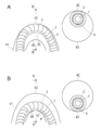
- FIG. 1 is a catheter; 2 is a catheter body; 3 is a reinforcing material; 4 is a wire; 5 is a low-sliding part; 6 is a surface lubricating part; 7 is a lumen (lumen); 9 indicates a guide wire; 10 indicates a deformation region; and 11 indicates a hub.
- FIG. 2 is a schematic sectional view taken along line A-A ′ of the catheter shown in FIG. 1.
- FIG. 2 4 indicates a wire material
- 5 indicates a low slip portion
- 6 indicates a surface lubrication portion
- 8 indicates an axis.
- 1 is a catheter
- 3 is a reinforcing material
- 4 is a wire
- 7 is a lumen (lumen)
- 10 is a deformed region
- 41 is a blood vessel
- 43 respectively indicate the inner blood vessel walls inside the blood vessel curved portion.
- FIG. 5 shows typically the other example of the structure of the catheter shown in FIG. In FIG.
- FIG. 8 7 is a lumen (lumen); 21 is a catheter; 23 is a reinforcing material; 24 is a wire; 30 is a deformed region; 41 is a blood vessel; And 43 show the inner wall of the blood vessel inside the blood vessel curve portion, respectively.
- FIG. 5 is a schematic sectional view taken along line A-A ′ of the catheter shown in FIG. 4.
- 24 indicates a wire material; 25 indicates a low slip portion; 26 indicates a surface lubrication portion; and 28 indicates an axis.
- It is a schematic diagram of the evaluation test apparatus (friction measuring machine) of the surface lubricity used in the Example.
- FIG. 9 It is a schematic diagram of the evaluation test apparatus (friction measuring machine) of the surface lubricity used in the Example.
- 50 is a friction measuring machine; 51 is a glass petri dish; 52 is a rubber terminal; 53 is a weight; and 54 is a sample.
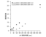
- 4 is a graph showing test results for evaluating the lubricity of a low-lubrication part with respect to ultraviolet irradiation time in Example 1.
- the present invention is a catheter having a lumen that is introduced and placed in a living body lumen, and the catheter has a deformation region that is parallel to the lumen of the catheter and extends in the axial direction.
- the deformation region is configured to be inside the curved portion when the catheter is bent to form a curved portion, and at least a part of the outer surface of the catheter is covered with a surface lubricating layer.
- a low slip portion (hereinafter also simply referred to as “low slip portion”) having lower lubricity than the surface lubrication layer is provided on at least a part of the deformation region on the outer surface of the catheter.
- the catheter is provided with the surface lubrication layer and the low slip portion at the same position in the axial direction of the catheter.
- the present invention is characterized in that when the catheter is bent, the low sliding portion is arranged on the outer surface at a position that is inside the curve of the catheter. Further, a surface lubrication layer is provided on the outer surface opposite to the deformation region with respect to the axial center of the lumen of the catheter, and the surface lubrication portion and the low slip portion are disposed at the same position in the axial direction of the outer surface of the catheter.
- the catheter having the above configuration can achieve both good operability when introduced into a living body lumen and high back-up performance when placed in the living body lumen. For this reason, by using the catheter of this invention, a catheter can be smoothly introduce
- the deformation region is preferably a region that is relatively difficult to stretch or a region that is relatively easy to contract in the circumferential direction of the catheter.
- the catheter has lubricity so that it can be smoothly introduced to a desired site, and has a backup property in order to hold (detain) it firmly at the desired site.
- the catheter has a surface other than the base end covered with a hydrophilic polymer substance. For this reason, it can introduce smoothly to a desired site
- the catheter is held or placed at a desired site for the purpose of administering or injecting a therapeutic agent or a contrast medium, the friction at the wall of the living body lumen (for example, blood vessel) is low, so that it has good backup power. Can not expect.
- the outer surface of the catheter of the present invention has a deformation region located inside the curve when the catheter is bent, and is eccentric with respect to the central axis (axial center) of the lumen of the catheter.
- the surface lubrication part and the low sliding part are installed at the same position in the axial direction. For this reason, the catheter can be smoothly inserted (introduced) to a position in a predetermined living body lumen (for example, blood vessel) due to the presence of the surface lubricating portion.
- a predetermined living body lumen for example, blood vessel
- the low sliding portion existing at the same position in the axial direction as the surface lubrication portion can be brought into contact with the living body lumen wall.
- the catheter of the present invention it is possible to improve the indwellability (back-up property) at the desired position while maintaining good operability at the time of introduction to the desired position.
- the catheter of the present invention has a deformed region configured to be inward when the catheter is bent, the outer surface of the deformed region is a living body lumen when the curved body lumen is advanced. Do not touch the wall. Therefore, when the catheter is advanced in a curved living body lumen or the like without the low sliding portion provided in the deformation region contacting the living body lumen wall, the low sliding portion does not hinder the movement. Further, the outer surface of the catheter located on the opposite side of the deformation region having the low sliding portion with respect to the axial center of the lumen of the catheter is covered with a surface lubricating layer.
- the catheter when the catheter is advanced in a curved living body lumen or the like, the portion having the surface lubrication layer on the outer surface of the catheter is always in contact with the living body lumen wall, so that better operability of the catheter can be achieved.
- the catheter when the catheter is to be fixed at a predetermined position, the catheter passes through the inside of the curved biological lumen wall by slightly pulling the catheter back to remove the bending of the catheter in the biological lumen. The outer surface of the deformed region of the catheter comes into contact with the living body lumen wall. Thereby, since the inside of the curved biological lumen wall and the low sliding portion of the outer surface of the catheter are in contact with each other, the catheter can be easily fixed in the biological lumen.
- excluding the bending of the catheter in the living body lumen means that the catheter in the state of FIG. 3A is inserted into the living body lumen by pulling the proximal side of the catheter so as to be in the state of FIG. 3B. This means shortening the length of the catheter.
- X to Y indicating a range means “X or more and Y or less”, “weight” and “mass”, “weight%” and “mass%”, “part by weight” and “weight part”. “Part by mass” is treated as a synonym. Unless otherwise specified, measurement of operation and physical properties is performed under conditions of room temperature (20 to 25 ° C.) / Relative humidity 40 to 50%.
- the catheter of the present invention may be used for any application, but in consideration of the effect of imparting lubricity due to contact with bodily fluids and blood and backup performance (indwellability), the catheter may be used in contact with bodily fluids and blood. preferable.
- the catheter of the present invention can improve operability and indwellability with an easy configuration, it is suitable to be applied to a catheter that needs to be reduced in diameter as used in the treatment of peripheral blood vessels. . For this reason, it is preferable to apply the catheter of the present invention to a microcatheter inserted into a thin peripheral blood vessel having a diameter of about 3 mm or less that has many branches and complicatedly meanders.
- the present invention will be described in detail by taking a catheter (especially a microcatheter) as a preferred embodiment of the present invention as an example.
- a catheter especially a microcatheter
- the present invention is not limited to the following, and is introduced and placed in other living body lumens. The same can be applied to the catheter to be used in the same manner or as appropriate.
- FIG. 1 is a plan view and a partially enlarged view showing an example of the overall configuration of a catheter according to an embodiment (first embodiment) of the present invention.
- FIG. 2 is a schematic sectional view taken along line A-A ′ of the catheter shown in FIG. In the following description, the right side in FIG.
- the catheter 1 of the present embodiment includes a flexible tubular catheter body 2 and a wire 4 that forms a reinforcing material 3 and a deformation region 10 disposed in the catheter body 2.
- a hub 11 is formed at the proximal end of the catheter body 2 as an injection port for injecting a therapeutic agent or a contrast medium.
- the reinforcing material 3 may have any shape, but preferably has a coil shape having a reinforcing effect.
- the coil-shaped reinforcing material is a shape of a reinforcing material formed by winding or twisting a reinforcing material in the shape of a single wire or rope, and the inside of the formed reinforcing material. A plurality of circular rings are formed.
- the reinforcing member 3 may extend in the entire axial direction from the distal end to the proximal end of the catheter body. At this time, the reinforcing material is preferably buried in the catheter body. Thereby, it is possible to produce a catheter having a large inner diameter and a small outer diameter while increasing the strength of the catheter.
- the winding pitch of the coil may be the same or different from the distal end to the proximal end of the catheter body.
- the base end region is wound at a relatively large winding pitch
- the distal end region is wound at a relatively small winding pitch
- the winding pitch is directed toward the distal end side. It is preferable that it is gradually reduced.
- the rigidity of the catheter in the distal region is smaller than that in the proximal region.
- the catheter having such a configuration include a catheter having a coil-shaped reinforcing material described in JP-A No. 2001-218851 (corresponding to US 2002/0022825 A1).
- the method for producing the catheter as described above is not particularly limited, but, for example, the method described in JP-A-2001-218851 can be similarly applied.
- the winding pitch of the coil means the distance in the longitudinal direction of the catheter between adjacent turns (windings) constituting the coil, in other words, adjacent in the longitudinal direction of the catheter 1. It means the length of the gap (distance) between the combined winding (winding) and winding (winding).
- the deformation region 10 is a region that is relatively difficult to extend in the circumferential direction of the catheter. Specifically, the deformation region 10 is formed on the same side as the wire 4 that is parallel to the lumen of the catheter body 2 and extends in the axial direction.
- the wire can regulate the movement of the coil-shaped reinforcing material moving in the direction in which the coil pitch increases. For this reason, when the catheter has a coil-shaped reinforcing material, the extension of the catheter on the side where the wire is inserted is restricted.
- the side opposite to the side where the wire rod located on the opposite side of the heart is placed is the outer side.
- the side on which the wire is provided is a deformation region that becomes the inner side when the catheter is bent.
- region can be easily produced by using a wire.
- the wire 4 may have any shape and is made of a material having lower rigidity than the reinforcing material 3.
- a linear wire is illustrated as an example of the wire 4.
- the catheter is configured by a coil-shaped reinforcing material and a wire
- the wire is disposed at the same position as the deformation region. That is, according to a preferred embodiment, the catheter has a coil-shaped reinforcing material and a wire extending parallel to the axial direction of the catheter, and the wire is arranged on the same side as the deformation region.
- region when a deformation
- the catheter can be prevented from increasing in outer diameter, and a minimally invasive and safe catheter can be provided.
- the extension of the coil in the case of a coil-shaped reinforcing material, the extension of the coil can be further restricted, and the movement of the coil in the direction in which the pitch of the coil increases can be better regulated.
- the stretchability in the axial direction of the catheter and the bending direction of the catheter can be controlled more effectively.
- the reinforcing member has a coil shape
- the side surface of the catheter having the deformation region and the side surface of the catheter where the deformation region does not exist there is a difference in stretchability between the side opposite to the side where there is.
- the stretchability of the catheter on the side surface provided with the wire is lower than that on the side surface where no wire is present.
- the bending direction of the catheter can be controlled by controlling the stretchability of the catheter in the axial direction.
- a surface lubrication portion is provided on the opposite side of the deformation region with respect to the axial center of the lumen of the catheter in contact with the blood vessel inner wall 42 outside the blood vessel bending portion.
- FIG. 3A a schematic sectional view taken along line X-X ′ of the catheter is also shown for the purpose of more clearly understanding the arrangement of the wire.
- the catheter base material in order to clarify the positional relationship between the reinforcing material 3 and the wire 4, the catheter base material (inner layer and outer layer) is shown in white, and the reinforcing material is shown in diagonal lines.
- the catheter 1 is slightly pulled back to remove the deflection as shown in FIG. To the inner wall 43 of the blood vessel.
- the low sliding portion is provided on the same side as the deformation region with respect to the axial center of the lumen of the catheter in contact with the blood vessel inner wall 43 inside the blood vessel curved portion.
- the catheter can be firmly fixed at a predetermined position (improving indwellability / back-up performance).
- FIG. 3B a schematic cross-sectional view taken along the line Y-Y ′ of the catheter is also shown for the purpose of more clearly understanding the arrangement of the wire.
- the catheter base material in order to clarify the positional relationship between the reinforcing material 3 and the wire 4, the catheter base material (inner layer and outer layer) is shown in white, and the reinforcing material is shown in diagonal lines. Therefore, by adopting the above configuration, it is possible to more effectively improve the operability at the time of introduction to a desired position and the indwellability (back-up performance) at the desired position. That is, it is preferable that the reinforcing member has a coil shape and the low slip portion is disposed on the same side as the deformation region with respect to the axial center of the lumen.
- one wire 4 exists parallel to the lumen of the catheter body 2 and extends in the axial direction, but the present invention is not limited to this form, and a plurality of wires May exist parallel to the lumen of the catheter body 2 and extending in the axial direction.
- the plurality of wires may be arranged eccentrically with respect to the central axis (axial center) of the catheter body (that is, biased to one side).
- a region in which the wires are arranged in an uneven manner is a deformation region.
- the number of wires is not particularly limited, but is preferably 1 to 8 and more preferably 1 to 4 in consideration of ease of production and diameter reduction.
- At least a part of the outer surface of the catheter body 2 is covered with a surface lubrication portion 6 and a low slip portion 5.
- the surface lubrication part 6 and the low slip part 5 are located in the same position of the axial direction of a catheter.
- the presence of the surface lubrication part improves lubricity in an aqueous liquid such as body fluid or blood, and the operability can be improved such that the catheter can be easily inserted into the living body lumen.
- the coating with the surface lubrication part can reduce damage to the tissue mucous membrane during the catheter introduction operation.
- the friction coefficient of the surface lubrication part is preferably 0.01 to less than 0.3, more preferably 0.03 to 0.2.
- the present invention includes both forms in which part or all of the surface of the base material (catheter body) constituting the catheter has surface lubricity.
- the entire surface (the entire surface) of the catheter does not need to have lubricity, but a surface lubrication part is formed at least on the surface part (some or all) that comes into contact with body fluids or blood. It is preferable. For this reason, a surface lubrication part does not need to be formed in the base end part side of a catheter, for example.
- a surface lubrication portion may be formed in the lumen of the catheter (inner wall of the lumen).
- the surface lubrication portions may be provided in all lumen lumens, or the surface lubrication portions may be provided in some lumen lumens. Further, it is not necessary to provide the surface lubrication part on the entire lumen of the catheter (inner wall of the lumen), and the surface lubrication part may be provided only on a part thereof.
- the low slip portion is a portion having low surface lubricity, and is installed on the outer surface of the catheter at the same position as the surface lubrication portion 6 in the axial direction.
- the friction coefficient of the low slip portion is preferably 0.3 to 4, more preferably 0.5 to 3.
- a straight bar shape is inserted into a catheter that has been cut to a length sufficient for measurement, and a linear shape is used as a sample.
- a double-sided tape is affixed to the back surface of the glass petri dish 51, and is fixed in the petri dish 51 so that the measurement surface of the sample is located at the top.
- the sliding resistance value (initial sliding resistance value) (gf) after reciprocating once at a distance of 10 mm at a moving speed of 1000 mm / min is measured.
- the moving distance may be appropriately changed according to the measurement length.
- the installation length of the surface lubrication part and the low sliding part is not particularly limited as long as desired operability and backup performance can be achieved.
- the installation length of the surface lubrication portion and the low slip portion is preferably 100 to 1000 mm, and more preferably 300 to 900 mm. With such an installation length, while maintaining good operability during insertion, the low-sliding portion comes into contact with the living body lumen wall more efficiently and more reliably when placed in the living body lumen. Therefore, higher backup performance can be achieved.
- the surface lubrication part and the low sliding part are formed on the outer surface of the catheter at the same position in the axial direction of the catheter.
- “the same position in the axial direction of the catheter” means that both the surface lubrication portion and the low slip portion are formed in a cross section at a certain position of the catheter.
- the formation position of the surface lubrication portion and the low slip portion on the outer surface of the catheter is not particularly limited as long as it is the same position in the axial direction of the catheter, and varies depending on the shape of the catheter, the introduction position, the indwelling position, and the like. In FIG.
- the low-sliding portion 5 is formed on the half of the outer surface of the catheter centering on the deformation region, and the surface lubricating portion 6 is formed on the other half of the outer surface of the catheter.
- the low slip portion 5 connects the center of the wire 4 and the axis 8 of the catheter.
- the angle (“ ⁇ ” in FIG. 2) formed by the line and the line connecting the end of the low slip portion 5 in the circumferential direction and the catheter axis 8 is preferably ⁇ 5 to ⁇ 90 °, more preferably ⁇ It is formed to be 15 to ⁇ 90 °.
- the two low-sliding portions 5 are separated from each other.
- the angle formed by the line connecting the midpoint between the wire rods and the catheter axis 8 and the line connecting the end of the low-sliding portion 5 in the circumferential direction and the catheter axis 8 is preferably ⁇ 5 to ⁇ 90. It is formed so as to have an angle of ⁇ 15 to ⁇ 90 °, more preferably ⁇ 15 to ⁇ 90 °.
- the surface lubrication portion 6 connects an extended line (line “L” in FIG. 2) of a line connecting the center of the wire 4 and the catheter axis 8 to an end portion in the circumferential direction of the surface lubrication portion 8.
- the angle formed by the line (“ ⁇ ′” in FIG. 2) is preferably ⁇ 5 to ⁇ 90 °, more preferably ⁇ 15 to ⁇ 90 °.
- the angle is an extension of the line connecting the midpoint between the two most distant wires and the catheter axis 8, and the surface lubricating portion.
- 8 is an angle formed by a line connecting the end portions in the circumferential direction.
- the operability can be further improved. Therefore, the presence of the low sliding portion and the surface lubrication portion at such a site allows the catheter to be inserted more smoothly into the curved portion, and the catheter is placed at a predetermined position in a living body lumen (for example, a blood vessel). Can be held more firmly.
- a living body lumen for example, a blood vessel.
- the above ⁇ and ⁇ ′ may be the same size or different sizes.
- the catheter body 2 is composed of a flexible tubular member, and a lumen (lumen) 7 is formed from the proximal end to the distal end.
- the lumen 7 functions as a guide wire lumen.
- the guide wire 9 is inserted into the lumen 7 as shown in FIG.
- the lumen 7 can also be used as a passage for a chemical solution, an embolic material, a contrast medium, or the like.
- the hub 11 functions as an insertion port of the guide wire 9 into the lumen 7, an injection port of a drug solution, an embolic material, a contrast medium, etc. into the lumen 7, and is gripped when operating the catheter 1. It also functions as a part.
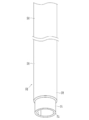
- the distal end portion of the catheter is a portion extended from the catheter body, and various conventionally known structures can be employed.
- the tip portion may be a looped shape or a substantially straight shape, and a member for imparting functions such as cleaning, suction, illumination, and imaging is attached to the tip portion. It may be done.
- the constituent material of the catheter body 2 is not particularly limited, but usually a flexible material is used.
- a flexible material for example, polyolefins such as polypropylene and ethylene-vinyl acetate copolymer, polyamides, polyesters such as polyethylene terephthalate (PET), polybutylene terephthalate (PBT), polyurethane, polyvinyl chloride, polystyrene resins, polytetrafluoroethylene, ethylene-
- Various flexible resins such as fluororesin such as tetrafluoroethylene copolymer, polyamide elastomer, polyurethane elastomer, polystyrene elastomer, polyester elastomer, fluoroelastomer, rubber materials such as silicone rubber and latex rubber, or these A combination of two or more of these can be used.
- the catheter body 2 may have a proximal end portion and a distal end portion located on the distal end side of the proximal end portion. At this time, it is preferable that the distal end side portion has lower rigidity than the proximal end side portion.
- the proximal end portion of the catheter body 2 is made of a material having a relatively high rigidity among the above-described constituent materials, and the distal end portion of the catheter body 2 is compared among the above-described constituent materials. For example, it may be made of a material having low mechanical rigidity. Thereby, the followability of a catheter improves.
- the structure of the catheter body is not particularly limited, but it may have a structure in which an inner layer and an outer layer are provided, and a reinforcing material and a wire forming a deformation region are embedded therebetween.
- the inner layer covers the inner periphery of the reinforcing material (coil), serves as a core for disposing the reinforcing material, and forms a lumen.
- the inner layer it is possible to use the same constituent material as the outer layer described in detail below, but it is preferable that the inner layer is made of a low friction material. As a result, friction on the inner surface of the inner layer is reduced, sliding resistance with the guide wire inserted into the lumen is reduced. The operation of removing the wire can be performed more easily and smoothly.
- the low friction material constituting the inner layer may be any material that can reduce friction on the inner surface of the inner layer, and is not particularly limited.
- fluorine resin nylon 66, polyetheretherketone, high density polyethylene and the like can be mentioned.
- a fluorine resin is more preferable.
- the fluorine-based resin include polytetrafluoroethylene, polyvinylidene fluoride, ethylene tetrafluoroethylene, perfluoroalkoxy resin, and the like.
- polytetrafluoroethylene is more preferable.
- the thickness of the inner layer 7 is not particularly limited. For example, it is preferably 5 to 50 ⁇ m, more preferably 5 to 40 ⁇ m from the viewpoint of reducing the diameter.
- the constituent material of the outer layer is not particularly limited, but usually a flexible material is used.
- a flexible material for example, polyolefins such as polypropylene and ethylene-vinyl acetate copolymer, polyamides, polyesters such as polyethylene terephthalate (PET), polybutylene terephthalate (PBT), polyurethane, polyvinyl chloride, polystyrene resins, polytetrafluoroethylene, ethylene- Various flexible resins such as fluororesin such as tetrafluoroethylene copolymer, polyamide elastomer, polyurethane elastomer, polystyrene elastomer, polyester elastomer, fluoroelastomer, rubber materials such as silicone rubber and latex rubber, or these A combination of two or more of these can be used.
- the thickness of the outer layer is not particularly limited, but is usually preferably about 0.05 to 0.15 mm, more preferably about 0.06 to 0.12
- the constituent material of the reinforcing material is not particularly limited, and examples thereof include a metal member or a non-metal member that is configured at least one of them.
- a metal member formed in a spiral shape, a non-metal member formed in a spiral shape, a metal member and a non-metal member stacked in a spiral shape, or the like can be used.
- a material constituting the metal member for example, one kind or a combination of two or more kinds of stainless steel, nickel-titanium alloy, platinum, iridium, tungsten and the like can be used.
- the nonmetallic member for example, one or two or more of carbon, polyamide, polyethylene terephthalate, polybutylene terephthalate, and the like can be used.
- the reinforcing material is preferably made of a radiopaque material such as tungsten, platinum, iridium or an alloy containing these. Thereby, a catheter can be visually recognized favorably under X-ray fluoroscopy.
- the reinforcing material may be made of the same material or different materials.
- the cross-sectional shape of the reinforcing material is not particularly limited, and may be any shape such as a circular shape or a flat shape (ribbon shape or belt shape).
- the thickness of the reinforcing material is not particularly limited.
- the diameter is preferably about 10 to 100 ⁇ m, more preferably about 30 to 60 ⁇ m.
- the reinforcing member preferably has a width of about 0.1 to 1.0 mm and a thickness of about 0.04 to 0.05 mm.
- the winding pitch of the reinforcing material is not particularly limited, but is preferably 50 to 500 ⁇ m, and more preferably 80 to 350 ⁇ m, for example. Within such a range, the catheter exhibits sufficient flexibility (low rigidity), can bend sufficiently along the curve in the blood vessel (body cavity), and the followability of the catheter can be improved.
- the constituent material of the wire forming the deformation region is not particularly limited, and examples thereof include a metal member or at least one of non-metal members.
- a metal member formed in a spiral shape, a non-metal member formed in a spiral shape, a metal member and a non-metal member stacked in a spiral shape, or the like can be used.
- a material constituting the metal member for example, one kind or a combination of two or more kinds of stainless steel, nickel-titanium alloy, platinum, iridium, tungsten and the like can be used.
- the nonmetallic member for example, one or two or more of carbon, polyamide, polyethylene terephthalate, polybutylene terephthalate, and the like can be used.
- the wire is made of a radiopaque material such as tungsten, platinum, iridium or an alloy containing these.
- the wire may be made of the same material as the reinforcing material, or may be made of a material different from the reinforcing material.
- the cross-sectional shape of the wire forming the deformation region is not particularly limited, and may be any shape such as a circular shape or a flat shape (ribbon shape or belt shape).
- the cross-sectional shape of the wire may be the same as or different from that of the reinforcing material.
- the thickness of the wire forming the deformation region is not particularly limited.
- the diameter is preferably about 10 to 100 ⁇ m, more preferably about 30 to 60 ⁇ m.
- the cross-sectional shape of the wire is a ribbon, the wire preferably has a width of about 0.1 to 1.0 mm and a thickness of about 0.04 to 0.05 mm.
- the thickness of the wire may be the same as or different from that of the reinforcing material.
- the reinforcing material explained in full detail about the form of a coil shape, this invention is not limited to the said form.
- the reinforcing material may have a mesh shape. That is, as another embodiment of the present invention, the catheter has a mesh-shaped reinforcing material and a wire extending in parallel with the axial direction of the catheter, and the wire is relative to the axial center of the lumen of the catheter. And place it on the opposite side of the deformation area.
- the mesh-shaped reinforcing material is the shape of a reinforcing material formed by weaving a reinforcing material having a shape such as a plurality of wires or ropes, and the mesh is formed by weaving a plurality of reinforcing materials in a lattice shape. It is formed to have a shape. In addition, even if the clearance gap is formed between adjacent reinforcement materials, the clearance gap does not need to be formed. By providing the catheter with the mesh-shaped reinforcing material and the wire, the rigidity on the side where the wire is provided can be increased.
- the reinforcing materials that form the mesh-shaped reinforcing material are partial. Since it is formed in a braided state, the movement of the reinforcing material is restricted. Therefore, the presence or absence of the wire does not significantly affect the stretchability of the reinforcing material, but does affect the physical properties of the catheter on the side containing the wire. For this reason, when the catheter has a mesh-shaped reinforcing material, the portion on the side where the wire is placed becomes hard and the catheter is difficult to bend.
- the side opposite to the side where the wire located on the opposite side to the heart is placed is the inner side. That is, when the catheter has a mesh-shaped reinforcing material, the opposite side of the wire to the axial center of the lumen of the catheter is a deformation region that becomes the inside when the catheter is bent. Thus, even in the case of a mesh-shaped reinforcing body, a deformation region can be easily produced by using a wire.
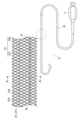
- FIG. 4 is a plan view and a partially enlarged view showing an example of the overall configuration of a catheter according to another embodiment (second embodiment) of the present invention.
- FIG. 5 is a schematic sectional view taken along line A-A ′ of the catheter shown in FIG. 4. In the following description, the right side in FIG.
- the catheter 21 of this embodiment includes a flexible tubular catheter body 22, and a reinforcing member 23 and a wire 24 disposed in the catheter body 22.
- the deformation region 30 does not exist in the wire 24, and preferably exists on the opposite side of the wire 24 with respect to the axial center of the lumen of the catheter.
- a hub 11 is formed at the proximal end of the catheter body 22 as an injection port for injecting therapeutic agents, contrast agents, and the like.
- the catheter body 22 is formed with a lumen extending from the proximal end to the distal end. When the catheter 21 is inserted into a blood vessel, a guide wire is inserted into the lumen (lumen). The lumen is also used as a flow path for a contrast medium or a chemical solution.
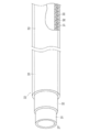
- the catheter body 22 has a middle layer 32 around a base tube (inner layer) 31 that is a tubular member. As shown in FIG. 6, an outer layer 33 may be further formed around the middle layer 32 as necessary. 5 and 6, a reinforcing material and a wire (not shown) are formed on the middle layer 32. Further, the distal end portion 27 of the catheter body 22 may not be provided with the intermediate layer 32 but may be configured only by the base tube (inner layer) 31. In this case, the distal end portion 27 may be composed of a base tube (inner layer) 31 and an outer layer 33.
- the hub 11 is attached to the proximal end of the catheter body 22.
- the hub 11 functions as an insertion port for a guide wire into a lumen (lumen), an injection port for a chemical solution or the like into the lumen (lumen), and also functions as a grip when operating the catheter. .
- the middle layer 32 is composed of the reinforcing member 23 and the wire 24.
- the reinforcing member 23 may have any shape, but preferably has a mesh shape having a reinforcing effect.
- the reinforcing member 23 may extend in the entire axial direction from the distal end to the proximal end of the catheter body.
- the mesh-shaped reinforcing material 23 includes a first reinforcing material 23A and a second reinforcing material 23B.
- the first reinforcing material 23A and the second reinforcing material 23B may be formed of any material (for example, a resin material or a metal material). The materials may be the same or different.
- the braid density of the first reinforcing material 23A and the second reinforcing material 23B is not particularly limited. Specifically, as shown in FIG. 4, the first reinforcing member 23A and the second reinforcing member 23B are braided at substantially the same density, and as shown in FIG. 7A, the first reinforcing member 23A is closely packed. And the form by which the 2nd reinforcement material 23B is sparsely braided, and the form by which the 1st reinforcement material 23A is sparse and the 2nd reinforcement material 23B is densely knitted as FIG. 7B shows. 7A and 7B, the low slip portion 25, the surface lubrication portion 26, and the wire rod 24 are omitted.
- Examples of such a catheter include a catheter having a mesh-shaped (knitted) reinforcing material described in JP-A-2001-87389.
- the method for producing the catheter as described above is not particularly limited.
- the method described in JP-A-2001-87389 (see particularly paragraphs “0101” to “0119”) is similarly applied. it can.
- the deformation region 30 is a region that is relatively easily contracted in the circumferential direction of the catheter. Specifically, the deformation region 30 is formed on the opposite side to the axial center of the lumen of the catheter with respect to the wire extending in the axial direction and parallel to the lumen (particularly the middle layer 32) of the catheter body 22.
- the wire may have any shape, but is preferably made of a material having lower rigidity than the reinforcing material. When the reinforcing material is mesh-shaped, the deformation region is configured on the opposite side to the wire with respect to the axial center of the lumen of the catheter.
- the catheter has a mesh-shaped reinforcing material and a wire extending parallel to the axial direction of the catheter, and the wire is deformed with respect to the axial center of the lumen of the catheter. Located on the opposite side of the area.
- the bending direction of the catheter can be controlled by controlling the rigidity in the axial direction of the catheter.
- the wire is knitted into the reinforcing material. Thereby, it can suppress that a wire moves and a position of a deformation
- the catheter can be prevented from increasing in outer diameter, and a minimally invasive and safe catheter can be provided.
- it is possible to effectively suppress and prevent the deviation of the wire from the reinforcing material with respect to deformation due to the catheter passing through the curved portion.
- the stretchability in the axial direction of the catheter and the bending direction of the catheter can be controlled more effectively.
- the reinforcing material has a mesh shape
- the side of the catheter where the wire is present particularly the side opposite to the side where the deformation region is present
- the wire are not present
- the reinforcing material is mesh-shaped
- the two reinforcing wires are composed of a braid
- the reinforcing wire is difficult to move. Therefore, when the reinforcing material is mesh-shaped, the bending direction when the catheter is bent is determined by the rigidity of the catheter. For this reason, as shown in FIG. 8A, when the catheter 21 passes through the blood vessel bending portion, the side surface with the wire 24 comes into contact with the blood vessel inner wall 42 outside the blood vessel bending portion.
- the bending direction of the catheter can be controlled by controlling the rigidity in the axial direction of the catheter.
- a surface lubrication part is provided on the opposite side of the deformation region with respect to the axial center of the lumen of the catheter in contact with the blood vessel inner wall 42 outside the blood vessel curved part.
- the catheter base material (inner layer and outer layer) is shown in white, and the reinforcing material is shown in diagonal lines.
- the cross section of the catheter is not circular as shown in the right side of FIG. 8A, but is shown in a circular shape in order to clearly show the position of the reinforcing member 3.
- the catheter 21 is slightly pulled back to remove the deflection as shown in FIG. To the inner wall 43 of the blood vessel.
- the low sliding portion is provided on the same side as the deformation region with respect to the axial center of the lumen of the catheter in contact with the blood vessel inner wall 43 inside the blood vessel curved portion.
- the catheter can be firmly fixed at a predetermined position (improving indwellability / back-up performance).
- FIG. 8B a schematic cross-sectional view taken along the line Y-Y ′ of the catheter is also shown for the purpose of more clearly understanding the arrangement of the wire.
- the catheter base material in order to clarify the positional relationship between the reinforcing material 3 and the wire 4, the catheter base material (inner layer and outer layer) is shown in white, and the reinforcing material is shown in diagonal lines. Moreover, in the said form, in order to show the position of the reinforcing material 3 clearly like FIG. 8A, it has shown in circular. Therefore, by adopting the above configuration, it is possible to more effectively improve the operability at the time of introduction to a desired position and the indwellability (back-up performance) at the desired position.
- the wire is disposed on the opposite side to the deformation region with respect to the axial center of the lumen of the catheter, and the low sliding portion is disposed in the deformation region. That is, it is preferable that the reinforcing member has a coil shape and the low slip portion is disposed on the same side as the deformation region with respect to the axial center of the lumen.
- one wire 24 exists parallel to the lumen of the catheter body 22 and extends in the axial direction, but the present invention is not limited to this form, and a plurality of wires May exist parallel to the lumen of the catheter body 22 and extending in the axial direction.
- the plurality of wires may be arranged eccentrically with respect to the central axis (axial center) of the catheter body (that is, biased to one side).
- a region in which the wires are arranged in an uneven manner is a deformation region.
- the number of wires is not particularly limited, but is preferably 1 to 8 and more preferably 1 to 4 in consideration of ease of production and diameter reduction.
- At least a part of the outer surface of the catheter body 22 is covered with a surface lubrication portion 26 and a low slip portion 25.
- the surface lubrication part 26 and the low slip part 25 are located in the same position of the axial direction of a catheter. Due to the presence of the surface lubrication part, it is possible to improve operability such as exhibiting lubricity in an aqueous liquid such as body fluid or blood, and allowing the catheter to be easily inserted into a living body lumen. Further, the coating with the surface lubrication part can reduce damage to the tissue mucous membrane during the catheter introduction operation.
- the friction coefficient of the surface lubrication part is preferably 0.01 to less than 0.3, more preferably 0.03 to 0.2.
- the present invention includes both forms in which part or all of the surface of the base material (catheter body) constituting the catheter has surface lubricity.
- the entire surface (the entire surface) of the catheter does not need to have lubricity, but a surface lubrication part is formed at least on the surface part (some or all) that comes into contact with body fluids or blood. It is preferable. For this reason, the surface lubrication part (and low slip part 25) does not need to be formed in the proximal end part side of a catheter, for example.
- a surface lubrication portion may be formed in the lumen of the catheter (inner wall of the lumen).
- the surface lubrication portions may be provided in all lumen lumens, or the surface lubrication portions may be provided in some lumen lumens.
- the surface lubrication part is provided in the lumen of the catheter (inner wall of the lumen), it is not necessary to provide the low sliding part at the same position in the axial direction of the catheter.
- the low slip portion is a portion having low surface lubricity, and is installed on the outer surface of the catheter at the same position as the surface lubrication portion 26 in the axial direction.
- the friction coefficient of the low slip portion is preferably 0.3 to 4, more preferably 0.5 to 3.
- the installation length of the surface lubrication part and the low sliding part is not particularly limited as long as desired operability and backup performance can be achieved.
- the installation length of the surface lubrication portion and the low slip portion is preferably 100 to 1000 mm, and more preferably 300 to 900 mm. With such an installation length, while maintaining good operability during insertion, the low-sliding portion comes into contact with the living body lumen wall more efficiently and more reliably when placed in the living body lumen. Therefore, higher backup performance can be achieved.
- the surface lubrication part and the low sliding part are formed on the outer surface of the catheter at the same position in the axial direction of the catheter.
- “the same position in the axial direction of the catheter” means that both the surface lubrication portion and the low slip portion are formed in a cross section at a certain position of the catheter.
- the formation position of the surface lubrication portion and the low slip portion on the outer surface of the catheter is not particularly limited as long as it is the same position in the axial direction of the catheter, and varies depending on the shape of the catheter, the introduction position, the indwelling position, and the like. In FIG.
- a half of the outer surface of the catheter centering on the wire and a deformation region are formed, a low slip portion 25 is formed in the deformation region, and a surface lubrication portion 26 is formed in the other half of the outer surface of the catheter.
- the low slip portion 25 connects the center of the wire 24 and the catheter axis 28.
- the end in the circumferential direction of the low slip portion 25 is preferably ⁇ 5 to ⁇ It is formed to be 90 °, more preferably ⁇ 15 to ⁇ 90 °.
- the two low-sliding portions 25 are separated from each other.
- the angle formed by the line connecting the midpoint between the wire rods and the catheter axis 28 and the end of the low-sliding portion 5 in the circumferential direction is preferably ⁇ 5 to ⁇ 90 °.
- it is formed to be ⁇ 15 to ⁇ 90 °.
- the surface lubrication portion 26 is formed by an angle formed by a line connecting the center of the wire 24 and the catheter axis 28 and a line connecting the end portion of the surface lubrication portion 26 in the circumferential direction and the catheter axis 28 (FIG. 9).
- ⁇ ' is preferably ⁇ 5 to ⁇ 90 °, more preferably ⁇ 15 to ⁇ 90 °.
- the angle is such that the extended line of the line connecting the midpoint between the two most distant wire rods and the catheter axis 28, and the surface lubrication portion This is an angle formed by a line connecting the end in the circumferential direction and the axis of the catheter.
- the operability can be further improved. Therefore, the presence of the low sliding portion and the surface lubrication portion at such a site allows the catheter to be inserted more smoothly into the curved portion, and the catheter is placed at a predetermined position in a living body lumen (for example, a blood vessel). Can be held more firmly.
- the above ⁇ and ⁇ ′ may be the same size or different sizes.
- the catheter body 22 is composed of a tubular member having flexibility, and a lumen (lumen) 27 is formed inside from the proximal end to the distal end.
- the lumen 27 functions as a guide wire lumen, and a guide wire (not shown) is inserted into the lumen 27 when the catheter 21 is inserted into a blood vessel.
- the lumen 27 can also be used as a passage for a chemical solution, an embolic material, a contrast medium, or the like.
- the hub 11 functions as an insertion port for the guide wire into the lumen 27, an injection port for a drug solution, an embolic material, a contrast medium, etc. into the lumen 27, and a gripping portion when operating the catheter 21. Also works.
- the distal end portion of the catheter is a portion extended from the catheter body, and various conventionally known structures can be employed.
- the tip portion may be a looped shape or a substantially straight shape, and a member for imparting functions such as cleaning, suction, illumination, and imaging is attached to the tip portion. It may be done.
- polyolefins such as polypropylene, polyethylene, and ethylene-vinyl acetate copolymer
- polyesters such as polyamide (eg, nylon 11, nylon 12, nylon 6), polyethylene terephthalate (PET), polybutylene terephthalate (PBT), Fluorine resins such as polyurethane, polyvinyl chloride, polystyrene resin, perfluoroalkoxy fluorine (PFA), polytetrafluoroethylene (PTFE), polyvinylidene fluoride, ethylene-tetrafluoroethylene copolymer (ETFE), acrylonitrile-butadiene -Styrene copolymerization resin (ABS resin), polyimide resin, polyamide elastomer, polyester elastomer, poly
- polyamide elastomer for example, nylon 6, nylon 64, nylon 66, nylon 610, nylon 612, nylon 46, nylon 9, nylon 11, nylon 12, N-alkoxymethyl modified nylon, hexamethylenediamine-isophthalic acid
- Typical examples are block copolymers in which various aliphatic or aromatic polyamides such as polycondensation polymers and metaxyloxydiamine-adipic acid polycondensation polymers are used as hard segments, and polymers such as polyesters and polyethers are used as soft segments.
- a polymer alloy (polymer blend) of a polyamide and a flexible resin, a graft copolymer or a random copolymer, a polyamide softened with a plasticizer or the like, or a mixture thereof can also be used.
- the polyester elastomer is typically a block copolymer of a saturated polyester such as polyethylene terephthalate or polybutylene terephthalate and a polyether or polyester. Further, these polymer alloys, those obtained by softening saturated polyester with a plasticizer, or a mixture thereof can also be used.
- an ABS resin or a polyether-based polyamide resin as a constituent material of the inner layer and the outer layer, since appropriate strength can be imparted.
- a fluorine-based resin, preferably PTFE for the inner layer, the operability of the guide wire or the treatment catheter inserted into the lumen can be improved.
- an X-ray opaque material such as barium sulfate, bismuth oxide and tungsten is blended in the material constituting the catheter body. It is preferable to keep it. Thereby, the insertion state and position of the catheter can be easily confirmed under fluoroscopy.
- the tip when the tip is composed of a base tube (inner layer) and an outer layer, the inner layer and the outer layer are each bonded by an appropriate adhesive, fused by heat, or integrally by covering molding or the like. Can be molded.
- the outer layer may have a multilayer structure in which different resins are laminated.
- the low friction layer may be formed on the inner surface of the catheter body using a low friction material, or the inner layer may be formed of a low friction material.
- the low friction material may be made of any material that can reduce friction on the inner surface of the lumen. Examples thereof include those composed of polytetrafluoroethylene, perfluoroalkoxy resin, polyethylene, polyimide, and the like.
- the inner layer can be formed by, for example, a dip coating method.
- the installation position of the low friction layer in the longitudinal direction of the catheter body is not particularly limited, but it is preferable that the low friction layer is installed over almost the entire length of the catheter body. Or you may comprise the catheter main body (base-material tube) with the material used for a low friction layer.
- a reinforcing layer may be placed on the outer surface of the catheter.
- the reinforcing layer may be composed of any material, but may be composed of, for example, a metal wire such as a steel wire or a stainless steel wire or a braided body of a metal ribbon.
- a coil or a slitted tube made of a hard material such as metal can be used as the reinforcing layer.
- the reinforcing layer may be provided on the inner surface of the catheter or may be embedded in the catheter.
- the installation position of the reinforcing layer in the longitudinal direction of the catheter body is arbitrary.
- the reinforcing layer may be disposed over the entire length of the catheter body, the reinforcing layer may be disposed at a place other than the distal end portion of the catheter body, or the reinforcing layer may be disposed at a part of the catheter body.
- the installation position of the reinforcing layer can be appropriately changed according to the use of the catheter, required characteristics, and the like.
- the constituent material of the reinforcing material is not particularly limited, and a resin material or a metal material can be used.
- the metal material include, but are not limited to, stainless steel, nickel-titanium alloy, platinum, iridium, and tungsten.
- the resin material examples include, but are not limited to, for example, polyester such as polyethylene terephthalate and polybutylene terephthalate, polyolefin such as polyethylene and polypropylene, polyvinyl chloride, polyamide, polyimide, polystyrene, thermoplastic polyurethane, polycarbonate, ABS resin, acrylic resin, polymethyl methacrylate (PMMA), polyacetal (PA), polyarylate, polyoxymethylene (POM), high tension polyvinyl alcohol, fluororesin, polyvinylidene fluoride (PVdF), polytetrafluoroethylene, ethylene
- EVOH saponified vinyl acetate
- polysulfone polyethersulfone
- polyetherketone polyphenylene oxide
- polyphenylene sulfide etc.
- Thermoplastic resins polyamide elastomer, polyester elastomer, polyurethane elastomer, various thermoplastic elastomers such as polyolefin elastomer, a polymer alloy containing any of these, or is a combination of two or more of thereof. In the latter case, it is preferable to select a reinforcing material (first reinforcing material, second reinforcing material) that is compatible with each other as the resin material of both.
- a reinforcing material first reinforcing material, second reinforcing material
- Examples of combinations of resin materials that are compatible with each other include polyurethane and polyamide, polyamide and polyamide elastomer, polyethylene or polypropylene and polyolefin elastomer, polyethylene terephthalate and polyester elastomer, polyurethane and polyester elastomer, highly plasticized polyvinyl chloride, and low plasticity. And polyvinyl chloride.
- the first reinforcing material and the second reinforcing material may be made of the same material or different materials.
- the reinforcing material (the first reinforcing material and the second reinforcing material) may be a single fiber, or may be a collection of fibers made up of single fibers.
- the cross-sectional shape of the reinforcing material (the first reinforcing material, the second reinforcing material) is not particularly limited, and may be any shape such as a circular shape or a flat shape (ribbon shape or belt shape). Note that the cross-sectional shapes of the first reinforcing material and the second reinforcing material may be the same or different.
- the thickness of the reinforcing material is not particularly limited.
- the diameter is preferably about 0.01 to 0.5 mm, more preferably about 0.03 to 0.3 mm.
- the cross-sectional shape of the reinforcing material is a ribbon, it is preferable that the width is about 0.03 to 5 mm and the thickness is about 0.03 to 0.2 mm.
- the diameter or width of the reinforcing material may not be constant over the entire length of the catheter body, and may be changed continuously or intermittently. For example, the diameter or width of one reinforcing material (first reinforcing material or second reinforcing material) is decreased and the other reinforcing material (second reinforcing material or The diameter or width of the first reinforcing member may be increased to further change the density of both.
- the constituent material of the wire is not particularly limited, and examples thereof include a material constituted by at least one of a metal member and a non-metal member.
- a metal member formed in a spiral shape, a non-metal member formed in a spiral shape, a metal member and a non-metal member stacked in a spiral shape, or the like can be used.
- a material constituting the metal member for example, one kind or a combination of two or more kinds of stainless steel, nickel-titanium alloy, platinum, iridium, tungsten and the like can be used.
- the nonmetallic member for example, one or two or more of carbon, polyamide, polyethylene terephthalate, polybutylene terephthalate, and the like can be used.
- the reinforcing material and the wire are made of a radiopaque material such as tungsten, platinum, iridium or an alloy containing them.
- the wire may be made of the same material as the reinforcing material, or may be made of a material different from the reinforcing material.
- the cross-sectional shape of the wire is not particularly limited, and may be any shape such as a circle or a flat shape (ribbon shape or belt shape).
- the cross-sectional shape of the wire may be the same as or different from that of the reinforcing material.
- the thickness of the wire is not particularly limited.
- the diameter is preferably about 10 to 100 ⁇ m, more preferably about 30 to 60 ⁇ m.
- the wire preferably has a width of about 0.1 to 1.0 mm and a thickness of about 0.04 to 0.05 mm. By arranging such a wire, the stretchability of the catheter can be easily controlled, and it is advantageous for reducing the diameter of the catheter. Note that the thickness of the wire may be the same as or different from that of the reinforcing material.
- the thickness of the surface lubrication part is not particularly limited as long as sufficient lubricity is obtained. It is preferable to have a thickness that can exhibit the property (lubricity maintenance property). From such a viewpoint, the thickness of the surface lubrication part (thickness of the surface lubrication part when not swollen) is preferably 0.1 to 20 ⁇ m, more preferably 0.5 to 10 ⁇ m, and still more preferably 1 to 5 ⁇ m. A range is desirable. If it is such thickness, a uniform film can be formed easily and surface lubricity and water retention (lubrication maintenance property) can fully be exhibited.
- the material constituting the surface lubrication part may be any material as long as it absorbs water and exhibits lubricity.
- a hydrophilic material etc. are mentioned. Specific examples are shown below.
- the hydrophilic material constituting the surface lubrication part is, for example, polyvinyl pyrrolidone, polyvinyl alcohol, polyethylene oxide polymer substance, cellulose polymer substance such as carboxymethyl cellulose, acrylamide polymer substance such as polyacrylamide and polydimethylacrylamide, Examples thereof include hydrophilic polymers such as hyaluronic acid, polyacrylic acid, maleic anhydride polymer materials such as maleic anhydride-methyl vinyl ether copolymer, water-soluble nylon (registered trademark), and derivatives thereof. These hydrophilic polymers can absorb water when wet and exhibit lubricity.
- hydrophilic polymers In order to firmly fix these hydrophilic polymers to the catheter (catheter base material), an appropriate amount of a crosslinking agent is added, or a reactive functional group is introduced into the hydrophilic polymer that forms the surface lubrication portion. Thus, it is preferable to crosslink the hydrophilic polymer.
- a monomer having a reactive functional group (hereinafter also referred to as “reactive monomer”) and a hydrophilic monomer are copolymerized.
- the reactive monomer means a monomer having a reactive functional group capable of performing a crosslinking reaction or the like.
- the “reactive functional group” means that it can undergo a crosslinking reaction with other monomers or react (bond) with a catheter substrate by heat treatment, light irradiation, electron beam irradiation, radiation irradiation, plasma irradiation, or the like. ) Refers to a functional group that can be
- the reactive functional group is not particularly limited, but may be a functional group such as an epoxy group, an acid halide group, an aldehyde group, an isocyanate group, or an acid anhydride group.
- the monomer having a reactive functional group is a monomer having an epoxy group, an isocyanate group, or an aldehyde group from the viewpoint of ease of handling, efficiency of a crosslinking reaction, and the like.
- reactive monomer is a monomer having an epoxy group, an isocyanate group, or an aldehyde group from the viewpoint of ease of handling, efficiency of a crosslinking reaction, and the like.
- monomers having an epoxy group are particularly preferred.
- These reactive functional groups may be present alone or in a plurality in the reactive monomer.
- the reactive monomer used in the present invention has a reactive functional group and is more hydrophobic than a hydrophilic monomer used in the production of the copolymer in body fluids or aqueous solvents. It is preferable.
- reactive monomers include monomers having an epoxy group in the molecule such as glycidyl acrylate, glycidyl methacrylate (GMA), methyl glycidyl methacrylate, and allyl glycidyl ether; (meth) acrylic acid Monomers with acid halide groups in the molecule such as chloride, (meth) acrylic acid bromide, (meth) acrylic acid iodide; (meth) acrylaldehyde, crotonaldehyde, acrolein, methacrolein and other aldehyde groups in the molecule Monomers having an isocyanate group such as (meth) acryloyloxymethyl isocyanate, (meth) acryloyloxyeth
- the monomer having a reactive functional group a monomer having an epoxy group is preferable, and glycidyl acrylate or glycidyl methacrylate, in which the reaction is accelerated by heat or the like and handling is relatively easy, is more preferable.
- These reactive monomers can be used alone or in combination of two or more.
- hydrophilic monomer is not particularly limited.
- acrylamide or a derivative thereof, vinylpyrrolidone, acrylic acid or methacrylic acid or a derivative thereof, polyethylene glycol acrylate or a derivative thereof, sugar or phospholipid is used as a side chain.
- water-soluble monomers such as maleic anhydride and maleic anhydride.
- acrylic acid methacrylic acid, N-methylacrylamide, N, N′-dimethylacrylamide, acrylamide, acryloylmorpholine, N, N′-dimethylaminoethyl acrylate, vinylpyrrolidone, 2-methacryloyloxyethyl phosphorylcholine, 2-methacryloyloxyethyl-D-glycoside, 2-methacryloyloxyethyl-D-mannoside, vinyl methyl ether, 2-hydroxyethyl (meth) acrylate, 4-hydroxybutyl (meth) acrylate, 2-hydroxypropyl (meth) acrylate 2-hydroxybutyl (meth) acrylate, 6-hydroxyhexyl (meth) acrylate, 1,4-cyclohexanedimethanol mono (meth) acrylate, 1-chloro-2-hydro Cypropyl (meth) acrylate, diethylene glycol mono (meth) acrylate, 1,6-he
- N, N-dimethylacrylamide, acrylamide, acrylic acid, methacrylic acid, N, N-dimethylaminoethyl acrylate, 2-hydroxyethyl methacrylate, and vinylpyrrolidone are preferable.
- N, N′-dimethylacrylamide and N, N′-dimethylaminoethyl acrylate are more preferable, and N, N′-dimethylacrylamide is particularly preferable.
- These hydrophilic monomers can be used alone or in combination of two or more.
- the hydrophilic polymer is preferably a copolymer of a reactive monomer and a hydrophilic monomer, and is formed from a monomer having a reactive functional group. More preferably, it is a block copolymer (block copolymer of a reactive monomer and a hydrophilic monomer) having a block to be formed and a block formed from a hydrophilic monomer.
- block copolymer block copolymer of a reactive monomer and a hydrophilic monomer
- the hydrophilic polymer comprises a reactive domain having an epoxy group-containing monomer as at least one structural unit and a hydrophilic monomer as at least one structural unit.
- the reactive functional epoxy group reacts with the adjacent epoxy group, so that the adjacent hydrophilic polymer forms a crosslinked structure and increases the strength of the surface lubrication part. be able to.
- the ratio between the hydrophilic monomer and the reactive monomer in the hydrophilic polymer is not particularly limited.
- the molar ratio of hydrophilic monomer to reactive monomer is preferably 1: 1 to 100: 1, More preferably, it is 5: 1 to 80: 1, and even more preferably 10: 1 to 50: 1. If it is such a ratio, the ratio of the hydrophilic part of a hydrophilic polymer and a reactive part can be made into a favorable range. If it is such a range, the surface lubrication part can fully exhibit high lubricity by a hydrophilic site
- the production method (polymerization method) of the hydrophilic polymer for polymerizing the hydrophilic polymer is not particularly limited, and a known polymerization method can be used. In general, a simple method using a polymerization initiator is used. The polymer may be polymerized.
- the hydrophilic polymer of the present invention is a block copolymer or graft copolymer, for example, living polymerization, polymerization using a macromonomer, polymerization using a polymer polymerization initiator, polycondensation, etc. However, it is not particularly limited.
- hydrophilic polymer surface lubrication part of the present invention
- maleic anhydride-methyl vinyl ether copolymer and glycidyl methacrylate-dimethylacrylamide copolymer are preferable, and glycidyl methacrylate-dimethylacrylamide copolymer (especially block copolymer). ) Is more preferable.
- the hydrophilic material exhibits lubricity when wet (water absorption) and reduces the frictional resistance between the catheter and the inner wall of the body lumen.
- These hydrophilic materials are coated by a conventionally known technique such as dip coating, spray coating, or surface graft polymerization, and are fixed as a surface lubricating portion.
- the method for producing the catheter of the present invention is not particularly limited, and known methods can be applied in the same manner or appropriately modified.
- a surface lubrication layer made of a hydrophilic material by selectively irradiating the deformation region configured to be inside when the catheter is bent, A low sliding portion with reduced lubricity can be formed.
- the presence of such a low slip portion increases the coefficient of friction when contacting the living body lumen wall (decreasing lubricity). For this reason, a favorable backup property can be ensured and a catheter with high operability and indwellability can be provided.
- the catheter manufacturing method of the present invention (i) after forming the surface lubrication part on the catheter surface, (ii) irradiating at least a part of the obtained surface lubrication part with energy rays. Forming a low sliding part.
- this invention is not limited to the following method.
- the catheter before forming the surface lubrication part and the low sliding part may be manufactured by any method, and a known manufacturing method can be applied in the same manner or appropriately modified by a known method.
- the catheter has a coil-shaped reinforcing material and a wire
- the inner layer tube is produced by extruding the inner layer material onto the core material using polytetrafluoroethylene.
- a surface lubrication part is formed on the catheter surface manufactured as described above.
- the material which comprises a surface lubrication part is as the above-mentioned.
- this step (i) is not particularly limited except that the above hydrophilic material is used, and can be applied in the same manner as in a known method or appropriately modified.
- the hydrophilic polymer (particularly, a block copolymer is preferred) is dissolved in a solvent to prepare a coating solution (lubricant coating agent, coating solution), and the coating solution is coated on the catheter substrate. Then, after forming the coating layer, a method of forming a surface lubrication part by subjecting the coating layer to a heat treatment to cause a hydrophilic polymer (block copolymer) to undergo a crosslinking reaction can be mentioned. That is, the method for forming the surface lubricating portion includes at least a lubricating coating agent coating step for coating the catheter base material with a lubricating coating agent, and a heating step for performing a heat treatment on the coating layer formed with the lubricating coating agent. Is preferred. By such a method, good lubricity and durability can be imparted to the catheter surface.
- the solvent used for dissolving the hydrophilic polymer according to the present invention is not particularly limited as long as it can dissolve the hydrophilic polymer.
- water alcohols such as methanol, ethanol, isopropanol and ethylene glycol, ketones such as acetone and methyl ethyl ketone, esters such as ethyl acetate, halides such as chloroform, olefins such as hexane, tetrahydrofuran and butyl ether
- ethers such as benzene, aromatics such as toluene, and amides such as N, N-dimethylformamide (DMF), but are not limited thereto.
- DMF N, N-dimethylformamide
- the concentration of the hydrophilic polymer in the coating solution is not particularly limited. From the viewpoint of obtaining coating properties and desired effects (lubricity and durability), the concentration of the hydrophilic polymer in the coating solution is 0.01 to 20% by weight, more preferably 0.05 to 15%. % By weight, more preferably 0.1 to 10% by weight. If the concentration of the hydrophilic polymer is in the above range, the lubricity and durability of the surface lubrication part to be obtained can be sufficiently exhibited. In addition, a uniform surface lubrication portion having a desired thickness can be easily obtained by one coating, which is preferable in terms of operability (for example, ease of coating) and production efficiency. However, even if it is out of the above range, it can be sufficiently utilized as long as it does not affect the operational effects of the present invention.
- the method for applying the coating solution to the catheter base surface is not particularly limited, and is a coating / printing method, dipping method (dipping method, dip coating method), spraying method (spray method), spin coating method, mixing.
- a conventionally known method such as a solution-impregnated sponge coating method can be applied.
- the dipping method dip coating method
- the dipping method is preferably used.
- a catheter catheter base material
- the inside of a system may be depressurized and defoamed. By degassing under reduced pressure, the solution can quickly penetrate into the narrow and narrow inner surface, and the formation of the surface lubrication part can be promoted.
- a surface lubrication part when the surface lubrication part is formed only on a part of the catheter, only a part of the catheter (catheter base material) is immersed in the coating liquid, and the coating liquid is made part of the catheter (catheter base material). By coating, a surface lubrication part can be formed in the desired surface part of a catheter (catheter base material).
- the present invention is not limited to these formation methods, and the surface lubrication portion can be formed by appropriately using conventionally known methods.
- the immersing method when it is difficult to immerse only a part of the catheter in the mixed solution, instead of the immersing method, another coating technique (for example, a coating liquid is applied to a predetermined surface portion of a medical device with a spray device) , A bar coater, a die coater, a reverse coater, a comma coater, a gravure coater, a spray coater, a coating method using a doctor knife, etc.) may be applied.
- the dipping method (dipping method) is possible because both the outer surface and the inner surface can be coated at once. Are preferably used.
- the catheter After immersing the catheter in the coating solution containing the hydrophilic polymer in this way, the catheter is taken out from the coating solution and subjected to heat treatment.
- the heat treatment conditions (temperature, time, etc.) of the coating liquid are not particularly limited as long as the surface lubrication part containing the hydrophilic polymer can be formed on the catheter.
- the heating temperature is preferably 60 to 200 ° C., more preferably 80 to 160 ° C., further preferably more than 80 ° C. and 150 ° C. or less, and particularly preferably 90 to 140 ° C.
- the heating time is preferably 15 minutes to 24 hours, more preferably 1 to 10 hours.
- the reactive functional group contained in the hydrophilic polymer is an epoxy group
- the epoxy group can be self-crosslinked by heating, but it reacts with an epoxy reaction catalyst or an epoxy group to promote the crosslinking reaction.
- a polyfunctional crosslinking agent that may be used may be included in the coating solution.
- the pressure condition during the heat treatment is not limited at all, and it can be performed under normal pressure (atmospheric pressure), or under pressure or reduced pressure.
- heat treatment means for example, an oven, a vacuum dryer, or the like can be used.
- the medical device according to the present invention can exhibit excellent lubricity and durability.
- Step (ii) In this step, at least a part of the surface lubrication portion formed in the step (i) is irradiated with energy rays to form a low slip portion.
- the lubricity of the irradiated part is lowered.
- the mechanism by which the lubricity of the irradiated part is lowered by irradiation with energy rays is unknown, but is presumed as follows. The present invention is not limited to the following mechanism.
- the hydrophilic polymer is a copolymer of a reactive monomer and a hydrophilic monomer
- the hydrophilic portion acts so as to exhibit lubricity in a body fluid or an aqueous solvent.
- the copolymer is irradiated with energy rays, active sites are generated at the hydrophilic site, a crosslinking reaction takes place starting from the active sites, and the cross-linking density of the surface lubrication part increases (the surface lubrication part of the surface lubrication part). The degree of swelling decreases). For this reason, the hydrophilic site
- the step of irradiating the energy beam is not particularly limited as long as the irradiation amount of the energy beam to the catheter surface is uniform, and a known method can be used.
- the lubricity may be controlled by gradually changing the irradiation amount of the energy beam, but the operability (line It is preferable to uniformly irradiate the energy rays from the viewpoints of easy control of the source) and ensuring backup performance.
- the energy beam generated by the radiation source is reflected on the first surface lubrication part after the energy beam from the source is reflected by the reflector. It may be irradiated. Energy beam irradiation can be applied to both batch processing and continuous processing.
- the energy beam may be anything as long as it can modify the surface of the surface lubrication part and reduce the lubricity in the surface lubrication part (increase the friction coefficient).
- Examples include ultraviolet rays, ⁇ rays, and electron beams. Among these, ultraviolet rays are preferable from the viewpoint of easy control of the irradiation amount and the irradiation range.
- the friction coefficient can be increased about 3 to 50 times in the region irradiated with ultraviolet rays compared to the region not irradiated with ultraviolet rays.
- “ultraviolet rays” generally refers to electromagnetic waves having a wavelength of 10 to 400 nm. Although it does not restrict
- the irradiation condition of the energy beam is not particularly limited, but it is preferable that the low sliding portion having the friction coefficient as described above can be formed.
- the coefficient of friction of the low slip portion (the degree of decrease in surface lubricity) can be appropriately controlled by controlling the type, wavelength, irradiation time, etc. of the energy beam used.
- the illuminance of ultraviolet rays is not particularly limited, but is preferably 1 to 1,000 mW / cm 2 .
- the irradiation energy is not particularly limited, but is preferably 100 to 20,000 mJ / cm 2 . By setting it as such a range, the low sliding part which has the above friction coefficients can be formed.
- the irradiation time of the ultraviolet rays is appropriately selected depending on the type of the hydrophilic material forming the surface lubricating layer, and is not particularly limited, but is usually preferably 1 second to 30 minutes, more preferably 10 seconds to 20 minutes. More preferably, it is 1 to 15 minutes, and particularly preferably 3 to 10 minutes.
- the irradiation atmosphere of ultraviolet rays may be in an air atmosphere or in an inert gas atmosphere.
- a region with high lubricity and a region with low lubricity can be formed in the surface lubricating layer made of the same material.
- the energy beam irradiation can be selectively performed at a predetermined position of the surface lubrication portion by irradiating the device with a finely focused energy beam.
- the surface lubrication part is protected (covered) with another member (material) so that the energy ray is irradiated to a part of the surface lubrication part and the energy beam is not irradiated to the other part.
- a portion other than the desired portion where the low slip portion is to be formed is covered with a mask, and the catheter is irradiated with energy rays.
- a catheter having a low sliding portion at a desired position can be easily manufactured. Further, when the obtained catheter is placed at a position in a predetermined living body lumen (for example, blood vessel), the low sliding portion comes into contact with the living body lumen wall, and the low sliding portion of the catheter and the living tube By the frictional force with the cavity wall (that is, high back-up property), it can be firmly held in the same position. On the other hand, when the catheter is inserted into the living body lumen, the catheter can be smoothly introduced to a desired position due to the presence of the surface lubrication portion covering the outer surface other than the low slip portion. Therefore, by using the catheter of the present invention, it is possible to improve the indwellability at the desired position while maintaining good operability at the time of introduction to the desired position.
- a predetermined living body lumen for example, blood vessel
- Example 1 Polyamide elastomer (Grill amide ELG5660 manufactured by EMS, Shore hardness D62, hard segment: nylon 12, soft segment: polytetramethylene glycol, soft segment content in elastomer: 27 wt%; both ends of the elastomer are sealed No) was press-molded to obtain a sheet having a thickness of 1 mm.
- a DMF solution (2) dissolved at a ratio of 5% by weight was prepared.
- the prepared sheet was cut into 1.5 cm ⁇ 5 cm and immersed in the DMF solutions (1) and (2) prepared above, respectively, and then heat-treated at 130 ° C. for 3 hours to obtain a thickness (not yet) Sheets (1) and (2) on which a surface lubricating layer having a thickness (when swollen) was 3 ⁇ m were formed.
- the surface lubricating layers of the sheets (1) and (2) are irradiated with ultraviolet rays (wavelength: 254 nm, illuminance: 16 mW / cm 2 ) for a predetermined time using an ultraviolet irradiation device PL16-110 manufactured by Sen Engineering. did.
- FIG. 11 shows the relationship between the ultraviolet irradiation time and the coefficient of friction of the obtained sample. From the results of FIG. 11, it can be said that in any coating agent, the lubricity of the surface lubricating layer is lowered according to the ultraviolet irradiation time, and the surface lubricity can be arbitrarily controlled.
Abstract
Description
本発明のカテーテルは、いずれの用途に使用されてもよいが、体液や血液との接触による潤滑性付与効果およびバックアップ性(留置性)を考慮すると、体液や血液と接触して用いられることが好ましい。具体的には、ガイディングカテーテル、造影用カテーテル、PTCA用、PTA用、IABP用等の各種バルーンカテーテル、超音波カテーテル、アテレクトミーカテーテル、内視鏡用カテーテル、留置カテーテル、薬液投与用カテーテル、脳や腹部等の臓器(例えば肝臓)内の目的部位に各種治療薬や塞栓物質、あるいは造影剤などを投与、注入するために用いられるマイクロカテーテル(塞栓術用カテーテル)等の種々のカテーテルに適用することができる。特に、本発明のカテーテルは、容易な構成により、操作性及び留置性を向上させることができるため、末梢血管の治療で使用するような細径化が必要なカテーテルに適用することが好適である。このため、本発明のカテーテルは、分岐が多く複雑に蛇行する直径3mm程度以下の細い末梢血管内に挿入されるマイクロカテーテルに適用するのが好ましい。 [catheter]
The catheter of the present invention may be used for any application, but in consideration of the effect of imparting lubricity due to contact with bodily fluids and blood and backup performance (indwellability), the catheter may be used in contact with bodily fluids and blood. preferable. Specifically, guiding catheters, contrast catheters, PTCA, PTA, and IABP balloon catheters, ultrasonic catheters, atherectomy catheters, endoscope catheters, indwelling catheters, drug solution administration catheters, brain and Apply to various catheters such as microcatheter (embolization catheter) used to administer and inject various therapeutic agents, embolic substances, or contrast agents to target sites in organs such as the abdomen (eg liver) Can do. In particular, since the catheter of the present invention can improve operability and indwellability with an easy configuration, it is suitable to be applied to a catheter that needs to be reduced in diameter as used in the treatment of peripheral blood vessels. . For this reason, it is preferable to apply the catheter of the present invention to a microcatheter inserted into a thin peripheral blood vessel having a diameter of about 3 mm or less that has many branches and complicatedly meanders.
測定に十分な長さとなるよう切断したカテーテルに芯金を挿入し、直線形状としたものをサンプルとして用いる。図10に示されるように、ガラスシャーレ51の裏面に両面テープを貼り付け、サンプルの測定面が上部に位置するようシャーレ51中に固定する。シャーレ51中に純水を満たし、摩擦測定機50(トリニティーラボ社製、ハンディートライボマスターTL201)の試料台にセットし、重り53により円柱状ゴム端子(φ=10mm)52に荷重200gを印加して、10mmの距離を1000mm/分の移動速度で1回往復運動させた後の摺動抵抗値(初回摺動抵抗値)(gf)を測定する。なお、評価は、n=3で行い、その平均値を摺動抵抗値とする。摺動抵抗値を荷重の値で除し、摩擦係数とする。尚、測定すべき領域の長さが10mmに満たない場合、移動距離を測定長に合わせて適宜変更してもよい。 (Friction coefficient measurement method)
A straight bar shape is inserted into a catheter that has been cut to a length sufficient for measurement, and a linear shape is used as a sample. As shown in FIG. 10, a double-sided tape is affixed to the back surface of the
本発明のカテーテルの製造方法は特に制限されず、公知の方法を同様にしてあるいは適宜修飾して適用できる。例えば、カテーテル外周(外表面)を親水性材料からなる表面潤滑層で被覆した後、カテーテルが湾曲した際に内側になるように構成された変形領域に選択的にエネルギー線を照射することにより、潤滑性が低下した低滑部を形成できる。このような低滑部の存在により、生体管腔壁と接触する際の摩擦係数が増加する(潤滑性が低下する)。このため、良好なバックアップ性を確保し、操作性及び留置性の高いカテーテルを提供することができる。 [Catheter manufacturing method]
The method for producing the catheter of the present invention is not particularly limited, and known methods can be applied in the same manner or appropriately modified. For example, by coating the outer periphery (outer surface) of the catheter with a surface lubrication layer made of a hydrophilic material, by selectively irradiating the deformation region configured to be inside when the catheter is bent, A low sliding portion with reduced lubricity can be formed. The presence of such a low slip portion increases the coefficient of friction when contacting the living body lumen wall (decreasing lubricity). For this reason, a favorable backup property can be ensured and a catheter with high operability and indwellability can be provided.
本工程では、カテーテル表面に表面潤滑部を形成する。 (Process (i))
In this step, a surface lubrication part is formed on the catheter surface.
本工程では、上記工程(i)で形成した表面潤滑部の少なくとも一部にエネルギー線を照射して、低滑部を形成する。表面潤滑部にエネルギー線を照射することによって、照射部位の潤滑性が低下する。ここで、エネルギー線照射により照射部位の潤滑性が低下するメカニズムは不明であるが、以下のように推測される。なお、本発明は、下記メカニズムに限定されない。すなわち、親水性高分子が反応性単量体と親水性単量体との共重合体の場合には、親水性部位が体液や水系溶媒中において潤滑性を発現するように作用する。一方、当該共重合体にエネルギー線を照射すると、親水性部位で活性点が生成し、当該活性点が起点となって架橋反応が起こり、表面潤滑部の架橋密度が増加する(表面潤滑部の膨潤度が低下する)。このため、表面潤滑部中の親水性部位が減少して、低滑部が形成される。 (Step (ii))
In this step, at least a part of the surface lubrication portion formed in the step (i) is irradiated with energy rays to form a low slip portion. By irradiating the surface lubrication part with energy rays, the lubricity of the irradiated part is lowered. Here, the mechanism by which the lubricity of the irradiated part is lowered by irradiation with energy rays is unknown, but is presumed as follows. The present invention is not limited to the following mechanism. That is, when the hydrophilic polymer is a copolymer of a reactive monomer and a hydrophilic monomer, the hydrophilic portion acts so as to exhibit lubricity in a body fluid or an aqueous solvent. On the other hand, when the copolymer is irradiated with energy rays, active sites are generated at the hydrophilic site, a crosslinking reaction takes place starting from the active sites, and the cross-linking density of the surface lubrication part increases (the surface lubrication part of the surface lubrication part). The degree of swelling decreases). For this reason, the hydrophilic site | part in a surface lubrication part reduces, and a low slip part is formed.
ポリアミドエラストマー(EMS社製グリルアミドELG5660、ショア硬度D62、ハードセグメント:ナイロン12、ソフトセグメント:ポリテトラメチレングリコール、エラストマー中におけるソフトセグメント含有量:27wt%;なお、該エラストマーの両末端は封止されていない)をプレス成型して、厚さ1mmのシートを得た。 Example 1
Polyamide elastomer (Grill amide ELG5660 manufactured by EMS, Shore hardness D62, hard segment:
Claims (6)
- 生体管腔内に導入および留置される内腔を有するカテーテルであって、
前記カテーテルは、前記カテーテルの内腔に平行で、かつ、軸方向に延在している変形領域を有し、
前記変形領域は、前記カテーテルが湾曲して湾曲部を形成した際、前記湾曲部の内側になるように構成されており、
前記カテーテルの少なくとも一部の外表面は、表面潤滑層で被覆されており、
前記カテーテルの外表面において、前記変形領域の少なくとも一部に前記表面潤滑層よりも潤滑性が低い低滑部が設けられており、前記カテーテルの軸方向の同一位置に、前記表面潤滑層と前記低滑部が設けられている、カテーテル。 A catheter having a lumen introduced and indwelled in a biological lumen,
The catheter has a deformation region parallel to the lumen of the catheter and extending in the axial direction;
The deformation region is configured to be inside the bending portion when the catheter is bent to form a bending portion,
At least a part of the outer surface of the catheter is covered with a surface lubricating layer,
On the outer surface of the catheter, at least a part of the deformation region is provided with a low slip portion having lower lubricity than the surface lubrication layer, and the surface lubrication layer and the catheter are located at the same position in the axial direction of the catheter. A catheter provided with a low sliding portion. - 前記変形領域は、前記カテーテルの周方向において、相対的に伸びにくい領域、または相対的に縮みやすい領域である、請求項1に記載のカテーテル。 The catheter according to claim 1, wherein the deformation region is a region that is relatively difficult to stretch or a region that is relatively easy to contract in the circumferential direction of the catheter.
- 前記カテーテルは、コイル状の補強材と、前記カテーテルの軸方向と平行にのびる線材と、を有し、
前記線材は、前記変形領域と同じ側に配置される、請求項1または2に記載のカテーテル。 The catheter has a coil-shaped reinforcing material and a wire extending in parallel with the axial direction of the catheter,
The catheter according to claim 1 or 2, wherein the wire is disposed on the same side as the deformation region. - 前記カテーテルは、メッシュ形状の補強材と、前記カテーテルの軸方向と平行にのびる線材と、を有し、
前記線材は、前記カテーテルの内腔の軸心に対して前記変形領域と反対側に配置される、請求項1または2に記載のカテーテル。 The catheter has a mesh-shaped reinforcing material and a wire extending in parallel with the axial direction of the catheter,
The catheter according to claim 1 or 2, wherein the wire is disposed on an opposite side of the deformation region with respect to an axial center of the lumen of the catheter. - 前記線材は、前記コイル状の補強材または前記メッシュ形状の補強材に編込まれている、請求項3または4に記載のカテーテル。 The catheter according to claim 3 or 4, wherein the wire is knitted into the coil-shaped reinforcing material or the mesh-shaped reinforcing material.
- 前記低滑部の摩擦係数は、0.3~4である、請求項1~5のいずれか1項に記載のカテーテル。 The catheter according to any one of claims 1 to 5, wherein a friction coefficient of the low slip portion is 0.3 to 4.
Priority Applications (3)
| Application Number | Priority Date | Filing Date | Title |
|---|---|---|---|
| EP14848794.5A EP3053624B1 (en) | 2013-09-30 | 2014-09-22 | Catheter |
| JP2015539205A JP6426613B2 (en) | 2013-09-30 | 2014-09-22 | catheter |
| US15/085,396 US10201680B2 (en) | 2013-09-30 | 2016-03-30 | Catheter |
Applications Claiming Priority (2)
| Application Number | Priority Date | Filing Date | Title |
|---|---|---|---|
| JP2013205366 | 2013-09-30 | ||
| JP2013-205366 | 2013-09-30 |
Related Child Applications (1)
| Application Number | Title | Priority Date | Filing Date |
|---|---|---|---|
| US15/085,396 Continuation US10201680B2 (en) | 2013-09-30 | 2016-03-30 | Catheter |
Publications (1)
| Publication Number | Publication Date |
|---|---|
| WO2015046148A1 true WO2015046148A1 (en) | 2015-04-02 |
Family
ID=52743284
Family Applications (1)
| Application Number | Title | Priority Date | Filing Date |
|---|---|---|---|
| PCT/JP2014/075091 WO2015046148A1 (en) | 2013-09-30 | 2014-09-22 | Catheter |
Country Status (4)
| Country | Link |
|---|---|
| US (1) | US10201680B2 (en) |
| EP (1) | EP3053624B1 (en) |
| JP (1) | JP6426613B2 (en) |
| WO (1) | WO2015046148A1 (en) |
Cited By (3)
| Publication number | Priority date | Publication date | Assignee | Title |
|---|---|---|---|---|
| JP2019511943A (en) * | 2016-02-24 | 2019-05-09 | インセプト、リミテッド、ライアビリティ、カンパニーIncept,Llc | Flexible enhanced neurovascular catheter |
| WO2020194907A1 (en) * | 2019-03-26 | 2020-10-01 | テルモ株式会社 | Catheter and treatment method |
| WO2021044923A1 (en) * | 2019-09-02 | 2021-03-11 | テルモ株式会社 | Catheter |
Citations (7)
| Publication number | Priority date | Publication date | Assignee | Title |
|---|---|---|---|---|
| JP2001087389A (en) | 1999-07-16 | 2001-04-03 | Terumo Corp | Method for manufacture of catheter, and catheter |
| JP2001218851A (en) | 2000-02-09 | 2001-08-14 | Terumo Corp | Catheter |
| JP2002017860A (en) * | 2000-07-05 | 2002-01-22 | Nippon Sherwood Medical Industries Ltd | Catheter |
| JP2008183226A (en) * | 2007-01-30 | 2008-08-14 | Hirakawa Hewtech Corp | Catheter tube, catheter tube continuous body, and method of manufacturing catheter tube |
| JP2012513249A (en) * | 2008-12-22 | 2012-06-14 | コーディス・コーポレイション | A deflection guide catheter used in minimally invasive medical procedures for mitral regurgitation therapy |
| JP2013090716A (en) * | 2011-10-25 | 2013-05-16 | Goodtec Co Ltd | Medical instrument |
| JP2013192717A (en) * | 2012-03-19 | 2013-09-30 | Sumitomo Bakelite Co Ltd | Medical instrument |
Family Cites Families (3)
| Publication number | Priority date | Publication date | Assignee | Title |
|---|---|---|---|---|
| EP1068876B1 (en) | 1999-07-16 | 2004-01-14 | Terumo Kabushiki Kaisha | Catheter and method of manufacturing the same |
| WO2007095549A2 (en) * | 2006-02-13 | 2007-08-23 | Medtronic, Inc. | Medical devices having textured surfaces |
| EP2810680B1 (en) | 2012-01-31 | 2016-06-22 | Terumo Kabushiki Kaisha | Catheter |
-
2014
- 2014-09-22 JP JP2015539205A patent/JP6426613B2/en active Active
- 2014-09-22 WO PCT/JP2014/075091 patent/WO2015046148A1/en active Application Filing
- 2014-09-22 EP EP14848794.5A patent/EP3053624B1/en active Active
-
2016
- 2016-03-30 US US15/085,396 patent/US10201680B2/en active Active
Patent Citations (8)
| Publication number | Priority date | Publication date | Assignee | Title |
|---|---|---|---|---|
| JP2001087389A (en) | 1999-07-16 | 2001-04-03 | Terumo Corp | Method for manufacture of catheter, and catheter |
| JP2001218851A (en) | 2000-02-09 | 2001-08-14 | Terumo Corp | Catheter |
| US20020022825A1 (en) | 2000-02-09 | 2002-02-21 | Takehiko Saitou | Catheter |
| JP2002017860A (en) * | 2000-07-05 | 2002-01-22 | Nippon Sherwood Medical Industries Ltd | Catheter |
| JP2008183226A (en) * | 2007-01-30 | 2008-08-14 | Hirakawa Hewtech Corp | Catheter tube, catheter tube continuous body, and method of manufacturing catheter tube |
| JP2012513249A (en) * | 2008-12-22 | 2012-06-14 | コーディス・コーポレイション | A deflection guide catheter used in minimally invasive medical procedures for mitral regurgitation therapy |
| JP2013090716A (en) * | 2011-10-25 | 2013-05-16 | Goodtec Co Ltd | Medical instrument |
| JP2013192717A (en) * | 2012-03-19 | 2013-09-30 | Sumitomo Bakelite Co Ltd | Medical instrument |
Non-Patent Citations (1)
| Title |
|---|
| See also references of EP3053624A4 |
Cited By (4)
| Publication number | Priority date | Publication date | Assignee | Title |
|---|---|---|---|---|
| JP2019511943A (en) * | 2016-02-24 | 2019-05-09 | インセプト、リミテッド、ライアビリティ、カンパニーIncept,Llc | Flexible enhanced neurovascular catheter |
| JP7012655B2 (en) | 2016-02-24 | 2022-01-28 | インセプト、リミテッド、ライアビリティ、カンパニー | Flexible enhanced neurovascular catheter |
| WO2020194907A1 (en) * | 2019-03-26 | 2020-10-01 | テルモ株式会社 | Catheter and treatment method |
| WO2021044923A1 (en) * | 2019-09-02 | 2021-03-11 | テルモ株式会社 | Catheter |
Also Published As
| Publication number | Publication date |
|---|---|
| US10201680B2 (en) | 2019-02-12 |
| US20160250442A1 (en) | 2016-09-01 |
| JP6426613B2 (en) | 2018-11-21 |
| EP3053624A4 (en) | 2017-06-07 |
| EP3053624B1 (en) | 2022-10-26 |
| EP3053624A1 (en) | 2016-08-10 |
| JPWO2015046148A1 (en) | 2017-03-09 |
Similar Documents
| Publication | Publication Date | Title |
|---|---|---|
| JP2705852B2 (en) | Lubricious catheter | |
| EP1123714B1 (en) | Catheter | |
| EP0872258B1 (en) | Balloon for medical tube and medical tube equipped with the same | |
| US20080091259A1 (en) | Selectively Light Curable Support Members for Medical Devices | |
| US11096807B2 (en) | Medical instrument having hydrophilic member and hydrophobic member stacked | |
| EP2371402B1 (en) | Guidewire coating presenting a crosslinking gradient | |
| JP5753495B2 (en) | Method for forming a reinforced tube | |
| CN103533967A (en) | Medical device having a lubricious coating with a hydrophilic compound in an interlocking network | |
| WO2006077951A1 (en) | Catheter and process for producing the same | |
| WO2015046148A1 (en) | Catheter | |
| EP0703798A1 (en) | Method for producing lubricious catheters | |
| JP2015066331A (en) | Catheter | |
| US10918835B2 (en) | Delivery system for active agent coated balloon | |
| JP3599784B2 (en) | Medical device with lubricious surface when wet | |
| WO2019059106A1 (en) | Method for producing medical instrument | |
| JP4744129B2 (en) | Catheter tube | |
| JP5484848B2 (en) | Method for producing medical elongated body | |
| WO2022118845A1 (en) | Catheter | |
| JP2023005465A (en) | Medical instrument and method for manufacturing medical instrument | |
| JP2019154828A (en) | Catheter and manufacturing method for the same | |
| JP2002282350A (en) | Lubricative medical instrument and manufacturing method therefor | |
| JP2007296007A (en) | Medical catheter tube and its manufacturing method |
Legal Events
| Date | Code | Title | Description |
|---|---|---|---|
| 121 | Ep: the epo has been informed by wipo that ep was designated in this application |
Ref document number: 14848794 Country of ref document: EP Kind code of ref document: A1 |
|
| ENP | Entry into the national phase |
Ref document number: 2015539205 Country of ref document: JP Kind code of ref document: A |
|
| REEP | Request for entry into the european phase |
Ref document number: 2014848794 Country of ref document: EP |
|
| WWE | Wipo information: entry into national phase |
Ref document number: 2014848794 Country of ref document: EP |
|
| NENP | Non-entry into the national phase |
Ref country code: DE |