WO2015046097A1 - ガスタービン燃焼器およびこれを備えたガスタービン機関 - Google Patents
ガスタービン燃焼器およびこれを備えたガスタービン機関 Download PDFInfo
- Publication number
- WO2015046097A1 WO2015046097A1 PCT/JP2014/074995 JP2014074995W WO2015046097A1 WO 2015046097 A1 WO2015046097 A1 WO 2015046097A1 JP 2014074995 W JP2014074995 W JP 2014074995W WO 2015046097 A1 WO2015046097 A1 WO 2015046097A1
- Authority
- WO
- WIPO (PCT)
- Prior art keywords
- main
- nozzle
- gas turbine
- fuel
- fuel injection
- Prior art date
- Legal status (The legal status is an assumption and is not a legal conclusion. Google has not performed a legal analysis and makes no representation as to the accuracy of the status listed.)
- Ceased
Links
Images

Classifications
-
- F—MECHANICAL ENGINEERING; LIGHTING; HEATING; WEAPONS; BLASTING
- F23—COMBUSTION APPARATUS; COMBUSTION PROCESSES
- F23R—GENERATING COMBUSTION PRODUCTS OF HIGH PRESSURE OR HIGH VELOCITY, e.g. GAS-TURBINE COMBUSTION CHAMBERS
- F23R3/00—Continuous combustion chambers using liquid or gaseous fuel
- F23R3/28—Continuous combustion chambers using liquid or gaseous fuel characterised by the fuel supply
- F23R3/286—Continuous combustion chambers using liquid or gaseous fuel characterised by the fuel supply having fuel-air premixing devices
-
- F—MECHANICAL ENGINEERING; LIGHTING; HEATING; WEAPONS; BLASTING
- F02—COMBUSTION ENGINES; HOT-GAS OR COMBUSTION-PRODUCT ENGINE PLANTS
- F02C—GAS-TURBINE PLANTS; AIR INTAKES FOR JET-PROPULSION PLANTS; CONTROLLING FUEL SUPPLY IN AIR-BREATHING JET-PROPULSION PLANTS
- F02C3/00—Gas-turbine plants characterised by the use of combustion products as the working fluid
- F02C3/04—Gas-turbine plants characterised by the use of combustion products as the working fluid having a turbine driving a compressor
-
- F—MECHANICAL ENGINEERING; LIGHTING; HEATING; WEAPONS; BLASTING
- F02—COMBUSTION ENGINES; HOT-GAS OR COMBUSTION-PRODUCT ENGINE PLANTS
- F02C—GAS-TURBINE PLANTS; AIR INTAKES FOR JET-PROPULSION PLANTS; CONTROLLING FUEL SUPPLY IN AIR-BREATHING JET-PROPULSION PLANTS
- F02C3/00—Gas-turbine plants characterised by the use of combustion products as the working fluid
- F02C3/14—Gas-turbine plants characterised by the use of combustion products as the working fluid characterised by the arrangement of the combustion chamber in the plant
-
- F—MECHANICAL ENGINEERING; LIGHTING; HEATING; WEAPONS; BLASTING
- F02—COMBUSTION ENGINES; HOT-GAS OR COMBUSTION-PRODUCT ENGINE PLANTS
- F02C—GAS-TURBINE PLANTS; AIR INTAKES FOR JET-PROPULSION PLANTS; CONTROLLING FUEL SUPPLY IN AIR-BREATHING JET-PROPULSION PLANTS
- F02C7/00—Features, components parts, details or accessories, not provided for in, or of interest apart form groups F02C1/00 - F02C6/00; Air intakes for jet-propulsion plants
- F02C7/22—Fuel supply systems
- F02C7/228—Dividing fuel between various burners
-
- F—MECHANICAL ENGINEERING; LIGHTING; HEATING; WEAPONS; BLASTING
- F23—COMBUSTION APPARATUS; COMBUSTION PROCESSES
- F23R—GENERATING COMBUSTION PRODUCTS OF HIGH PRESSURE OR HIGH VELOCITY, e.g. GAS-TURBINE COMBUSTION CHAMBERS
- F23R3/00—Continuous combustion chambers using liquid or gaseous fuel
- F23R3/28—Continuous combustion chambers using liquid or gaseous fuel characterised by the fuel supply
- F23R3/30—Continuous combustion chambers using liquid or gaseous fuel characterised by the fuel supply comprising fuel prevapourising devices
- F23R3/32—Continuous combustion chambers using liquid or gaseous fuel characterised by the fuel supply comprising fuel prevapourising devices being tubular
-
- F—MECHANICAL ENGINEERING; LIGHTING; HEATING; WEAPONS; BLASTING
- F23—COMBUSTION APPARATUS; COMBUSTION PROCESSES
- F23R—GENERATING COMBUSTION PRODUCTS OF HIGH PRESSURE OR HIGH VELOCITY, e.g. GAS-TURBINE COMBUSTION CHAMBERS
- F23R3/00—Continuous combustion chambers using liquid or gaseous fuel
- F23R3/28—Continuous combustion chambers using liquid or gaseous fuel characterised by the fuel supply
- F23R3/34—Feeding into different combustion zones
- F23R3/343—Pilot flames, i.e. fuel nozzles or injectors using only a very small proportion of the total fuel to insure continuous combustion
-
- F—MECHANICAL ENGINEERING; LIGHTING; HEATING; WEAPONS; BLASTING
- F05—INDEXING SCHEMES RELATING TO ENGINES OR PUMPS IN VARIOUS SUBCLASSES OF CLASSES F01-F04
- F05D—INDEXING SCHEME FOR ASPECTS RELATING TO NON-POSITIVE-DISPLACEMENT MACHINES OR ENGINES, GAS-TURBINES OR JET-PROPULSION PLANTS
- F05D2220/00—Application
- F05D2220/30—Application in turbines
- F05D2220/32—Application in turbines in gas turbines
-
- F—MECHANICAL ENGINEERING; LIGHTING; HEATING; WEAPONS; BLASTING
- F05—INDEXING SCHEMES RELATING TO ENGINES OR PUMPS IN VARIOUS SUBCLASSES OF CLASSES F01-F04
- F05D—INDEXING SCHEME FOR ASPECTS RELATING TO NON-POSITIVE-DISPLACEMENT MACHINES OR ENGINES, GAS-TURBINES OR JET-PROPULSION PLANTS
- F05D2240/00—Components
- F05D2240/35—Combustors or associated equipment
Definitions
- the present invention relates to a gas turbine combustor configured to prevent the occurrence of combustion vibrations and a gas turbine engine equipped with the gas turbine combustor.
- a pilot burner is disposed at the center of a combustion cylinder, and a plurality of main burners are disposed so as to surround the periphery of the pilot burner.
- Gas turbine engines include those that burn gaseous fuel such as LNG and those that burn liquid fuel such as kerosene and A heavy oil.
- a mixture of compressed air and fuel is generated in advance by injecting fuel into the flow of compressed air at the premixing nozzle of the main burner.
- the air-fuel mixture is ignited by the flame injected from the pilot burner and burned to generate high-temperature and high-pressure combustion gas to drive the turbine on the downstream side.
- the ratio between the air amount and the fuel amount can be adjusted relatively freely, and the air ratio (excess air ratio) in combustion can be increased.
- the amount of NOx produced can be reduced by lowering the temperature.
- combustion vibration is likely to occur.
- the fluctuation range of the combustion pressure is amplified, the combustion becomes unstable, and low cycle vibration and noise due to the periodic fluctuation of the pressure of the combustor are generated.
- Combustion vibration occurs when a periodic pressure fluctuation occurs in the combustor due to combustion, and this pressure fluctuation period coincides with the hydrodynamic natural frequency of the combustor.
- the heat generation position by the injection flames injected from each main burner is the same position in the axial direction of the combustor. In this heat generation concentration area, the pressure of the combustion gas suddenly increases due to the temperature rise, and the pressure wave propagates in the combustor, and the combustion vibration is easily excited by resonance in the combustor. It becomes a state.
- Patent Documents 1 and 2 disclose gas turbine combustors configured to suppress such combustion vibration.
- Combustion vibration is suppressed by making the (shape) different and avoiding that the heat generation position by the injection flame is concentrated at the same position in the axial direction of the combustor.
- the gas turbine combustor disclosed in Patent Document 2 differs from the shape of the elliptical extension pipes connected to the downstream side of the plurality of main nozzles (premixing nozzles), so The premixed gas is prevented from being ignited and combusted at the same position in the axial direction of the combustor, the concentration of the heat generation position by the injection flame is prevented, and the combustion vibration is suppressed.
- the swirl angle of the swirler provided in the premixing pipe as in Patent Document 1 or the shape of the elliptical extension pipe as in Patent Document 2 is different from that of the gas turbine combustor. For example, a large cost is required to modify an existing gas turbine combustor.
- the present invention has been made in view of the above circumstances, and in the case of using liquid fuel, it is possible to reduce the generation amount of NOx and to prevent the occurrence of combustion vibration by a simple and high cost performance configuration. It is an object of the present invention to provide a gas turbine combustor that can be used and a gas turbine engine including the same.
- the gas turbine combustor according to the first aspect of the present invention includes a pilot burner disposed at the center of the combustion cylinder, and a plurality of main burners disposed so as to surround the pilot burner.
- the main burner has a main nozzle installed at the center of a cylindrical premixing nozzle, and an extension nozzle connected to a downstream side of the premixing nozzle from a fuel injection hole provided around the main nozzle
- the liquid fuel is injected toward the inner surface of the main body, and the injection pattern of the liquid fuel injected from the fuel injection hole toward the inner surface of the extension nozzle is different among the plurality of main burners. Is set.
- this gas turbine combustor since the injection pattern of the liquid fuel is different among the plurality of main burners, the concentration distribution of the mixture of compressed air and liquid fuel between the main burners can be changed. As a result, there is a difference in the length and shape of the combustion flames injected from each main burner, so that the heat generation distribution and the maximum heat generation point due to the plurality of combustion flames are concentrated at the same position in the axial direction of the combustor. It is possible to prevent combustion vibrations.
- the air shape pressure loss does not change, and the air distribution is not biased. Therefore, the generation of NOx due to an increase in the average flame speed with a specific main burner with a small amount of air is suppressed, and the amount of NOx generated in the entire combustor can be reduced.
- the injection angle of the liquid fuel in the fuel injection holes is different among the plurality of main burners. It can be considered.
- the position of the fuel injection hole in the main nozzle may be different among the main burners.
- the position of the fuel injection hole mentioned here may be an axial position, a circumferential position, a fuel injection hole installation pattern, or the like of the main nozzle of the fuel injection hole.
- the number of the fuel injection holes in the main nozzle is made different among the main burners.
- the diameter of the fuel injection hole in the main nozzle is made different among the main burners.
- the liquid fuel injection patterns are different among the multiple main burners, and the length and shape of the combustion flames injected from each main burner are made different so that heat is generated by the multiple combustion flames. It is possible to prevent the distribution (maximum heating point) from concentrating on the same position of the combustor and to suppress combustion vibration.
- the injection pattern may be made different by making the position of the main nozzle relative to the premixing nozzle changeable in at least one of the axial direction and the circumferential direction.
- the position of the main nozzle in at least one of the axial direction and the circumferential direction even if the fuel injection angle, position, quantity, hole diameter, etc. of the fuel injection hole in the main nozzle itself are unchanged.
- the position of the fuel injection hole can be changed in the axial direction and the circumferential direction. For this reason, the injection pattern of the liquid fuel injected from a plurality of main burners can be set more variously.
- a gas turbine engine includes a compressor for compressing air, and gas turbine combustion having any one of the above-described configurations in which fuel is injected into the air compressed in the compressor and burned. And a turbine driven by expansion of combustion gas ejected from the gas turbine combustor.
- the fuel injection hole provided in each main nozzle is changed, or only the axial position and the circumferential position of the main nozzle are changed. Due to the relatively simple and inexpensive structure, the concentration distribution of the mixture of compressed air and liquid fuel between the main burners is changed, and there is a difference in the length (shape) of the flame injected from each main burner. Thus, the heat generation position (heat generation distribution) due to the plurality of injection flames can be prevented from concentrating at the same position in the axial direction of the combustor, and combustion vibration can be suppressed.
- combustion vibration is generated with a simple and high cost performance configuration. Can be prevented.
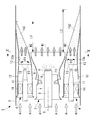
- FIG. 1 is a longitudinal sectional view of a gas turbine combustor showing a first embodiment of the present invention.
- the gas turbine combustor 1 is mounted on a gas turbine engine (not shown).
- a gas turbine engine includes a compressor that compresses air, a gas turbine combustor that injects fuel into the air compressed in the compressor, and a combustion gas that is ejected from the gas turbine combustor.
- the turbine is driven by the expansion of the gas turbine, and the turbine is rotated at high speed by using the energy of the combustion gas generated in the gas turbine combustor, and the generator is driven by obtaining the shaft output.
- the gas turbine combustor 1 which concerns on this invention is used as said gas turbine combustor.
- the gas turbine combustor 1 includes a combustion cylinder 2 forming an outer peripheral portion thereof, a single pilot burner 3 disposed along a central axis C of the combustion cylinder 2, and so as to surround the periphery of the pilot burner 3.
- the apparatus has a typical premixing configuration including a plurality of (for example, eight) main burners 4 arranged at intervals.
- the compressed air A compressed by a compressor flows from the left side toward the right side in FIG. 1 in the gas turbine combustor 1 (combustion cylinder 2).
- the pilot burner 3 is provided with a shaft-like pilot nozzle 5 at its axial center.
- a plurality of fuel injection holes 6 are formed at the tip of the pilot nozzle 5 on the downstream side.
- a substantially funnel-shaped pilot nozzle outer cylinder 7 is attached so as to surround the pilot nozzle 5 with a space therebetween. The diameter of the pilot nozzle outer cylinder 7 is gradually reduced toward the downstream side of the flow of the compressed air A.
- a plurality of wing-shaped pilot swirlers 8 are installed on the inner peripheral surface of the pilot nozzle outer cylinder 7 so as to stand up toward the pilot nozzle 5 side. Since these pilot swirlers 8 are provided with pitch angles that are inclined in the same direction, the flow of the compressed air A flowing inside the pilot nozzle outer cylinder 7 becomes a swirling flow (swirl flow).
- a pilot cone 9 is provided so as to cover the periphery of the pilot nozzle 5.
- the pilot cone 9 is formed in a substantially funnel shape whose diameter increases toward the downstream side of the flow of the compressed air A, and on the downstream side of the pilot nozzle outer cylinder 7 inside the upstream end portion of the pilot cone 9. The end portions are inserted with a short gap in the radial direction.
- Liquid fuel F1 is injected into the swirling flow (swirl flow) of the compressed air A flowing inside the pilot nozzle outer cylinder 7 from the fuel injection hole 6 of the pilot nozzle 5, and the compressed fuel A is swirling so that the liquid fuel Mixing with F1 is promoted. In this manner, the fuel mixture M1 is generated when the liquid fuel F1 is preliminarily mixed with the compressed air A in the pilot burner 3.
- the fuel mixture M1 is ejected from the pilot cone 9 toward a combustion region (not shown), ignited by a seed flame (not shown), and diffusion combustion is performed inside and downstream of the pilot cone 9.
- the pilot cone 9 prevents the fuel mixture M1 injected from the pilot burner 3 and its combustion flame from diffusing in the centrifugal direction, and interferes with the fuel mixture M2 combustion flame from the main burner 4 described later. Is prevented.
- the plurality of main burners 4 are provided with shaft-shaped main nozzles 11 at the respective shaft centers. These main nozzles 11 have a tapered cone shape in which the downstream end of the flow of the compressed air A becomes narrower toward the tip.
- a premixing nozzle 12 is provided so as to cover the periphery of the main nozzle 11.
- the premixing nozzle 12 has a substantially cylindrical shape, and an upstream inlet portion is expanded in a bell mouth shape, and an extended nozzle 13 is connected to a downstream outlet portion.
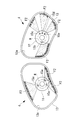
- the extension nozzle 13 has a circular shape at the end on the premixing nozzle 12 side, but the opening shape at the end on the outlet side has an inner peripheral surface of the combustion cylinder 2 and the pilot cone 9 as shown in FIG. It has a substantially fan shape along the outer peripheral surface.
- a plurality of wing-shaped main swirlers 14 (see FIG. 1) extending radially from the outer peripheral surface of the main nozzle 11 are fixed to the inner peripheral surface of the premixing nozzle 12, and the main nozzle 11 is premixed by these main swirlers 14. 12 is fixed at the center. Since each main swirler 14 is provided with a pitch angle inclined in the same direction, a swirl flow (swirl flow) in the same rotation direction is generated in the flow of the compressed air A passing through the inside of each premixing nozzle 12. .
- the main nozzle 11 is provided with a plurality of fuel injection holes 15 on the outer peripheral surface of the cone near its tip, from which liquid fuel F2 is injected.
- the liquid fuel F ⁇ b> 2 is injected obliquely toward the inner surface 13 a of the extension nozzle 13, atomized by hitting the inner surface 13 a, and mixed with the compressed air A. Since the compressed air A is swirling inside the premixing nozzle 12, mixing of the compressed air A and the liquid fuel F2 is promoted.
- the fuel mixture M2 is generated by premixing the liquid fuel F2 with the compressed air A in the main burner 4, and this fuel mixture M2 is ejected from the extension nozzle 13 toward a combustion region (not shown).
- the fuel mixture M1 injected from the pilot burner 3 is ignited by the combustion flame to generate combustion flames FA1 and FA2.
- the fuel injection holes 15 do not necessarily have to be provided in the main nozzle 11.
- the fuel injection holes 15 need only be provided around the main nozzle 11, such as the blade surface of the main swirler 14.
- a turbine (not shown) of the gas turbine engine is driven by the expansion pressure of the combustion gas of the combustion flame ejected from the pilot burner 3 and the main burner 4 and is taken out as an output, and a compressor provided coaxially with the main shaft of the turbine is driven. Compressed air A is supplied.
- the injection pattern of the liquid fuel F2 injected from the fuel injection hole 15 provided in the main nozzle 11 toward the inner surface 13a of the extension nozzle 13 is different among the plurality of main burners 4 (main nozzles 11). Is set to
- the injection angle of the liquid fuel F2 in the fuel injection hole 15 differs between the main burners 4 (main nozzles 11).
- the fuel injection angle ⁇ 2 of the fuel injection hole 15 of the lower main nozzle 11 is set to be narrower than the fuel injection angle ⁇ 1 of the fuel injection hole 15 of the upper main nozzle 11. .
- the vertical cross-sectional view of the lower half of FIG. This is the difference in the injection pattern.
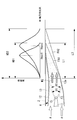
- FIG 3 shows the heat distribution along the axial direction in the combustion cylinder 2 by the combustion flames FA1 and FA2.
- the heat generation distributions HD1 and HD2 The axial length is different, and the axial positions of the highest heat generation points Hmax1 and Hmax2 are also different.
- the fuel injection angle of the fuel injection hole 15 is set to at least two types of ⁇ 1 and ⁇ 2, and the arrangement is, for example, half of the eight premixing nozzles 12 (main nozzles 11), which are alternately arranged. It is conceivable that the fuel injection angles ⁇ 1 and ⁇ 2 are grouped in groups of four, arranged symmetrically, or randomly arranged. Further, the fuel injection angle may be set larger than the two types of ⁇ 1 and ⁇ 2.
- the gas turbine combustor 1 configured as described above, since the injection pattern of the liquid fuel F2 is different among the plurality of main burners 4, the compressed air A and the liquid fuel F2 between the main burners 4 are different.
- the concentration distribution of the fuel mixture M2 can be changed.
- the lengths L1 and L2 of the combustion flames FA1 and FA2 injected from the main burners 4 and the shapes of the combustion flames FA1 and FA2 are differentiated, and the heat generation distributions HD1 and HD2 (maximum heat generation points Hmax1, Hmax 2) can be prevented from concentrating at the same position in the axial direction of the combustion cylinder 2, and combustion vibration in the gas turbine combustor 1 can be effectively suppressed.
- the injection angles ⁇ 1 and ⁇ 2 of the liquid fuel F2 in the fuel injection holes 15 of the main nozzle 11 are set to the plurality of main burners 4 respectively. Therefore, the combustion vibration can be suppressed by making the injection pattern of the liquid fuel F2 different among the plurality of main burners 4 with a simple and high cost performance configuration.
- the shape of the inflow path of the compressed air A is kept the same among the plurality of main burners 4, the air shape pressure loss does not change, and the air distribution is not biased. Therefore, the generation of NOx due to the increase in the average flame speed by the specific main burner 4 with a small amount of air is suppressed, and the amount of NOx generated in the gas turbine combustor 1 as a whole can be reduced.
- the four fuel injection holes 15 are arranged in a cross shape at intervals of 90 degrees in the front view, respectively, in the main nozzles 11 of all the main burners 4.
- this mode is not necessarily required, and the number and arrangement position (interval) of the fuel injection holes 15 may be varied.
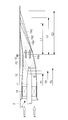
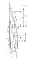
- FIG. 4 is a longitudinal sectional view of the main burner 4 and the injection flame showing the second embodiment of the present invention.
- the main nozzle 11 of each main burner 4 has a structure in which the injection pattern of the liquid fuel F2 injected from the fuel injection hole 15 toward the inner surface 13a of the extension nozzle 13 is different among the plurality of main burners 4.
- the positions of the fuel injection holes 15 in the axial direction are different.
- the position of the fuel injection hole 15 in each main nozzle 11 is set to three types P1, P2, and P3 in the axial direction, and approaches the tip side of the main nozzle 11 in the order of P1, P2, and P3.
- a plurality of main burners 4 provided with the main nozzles 11 whose positions of the fuel injection holes 15 are different in the axial direction are installed in the combustion cylinder 2 at random or in groups.
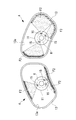
- FIG. 5 is a front view of the main burner 4 (main nozzle 11, fuel injection hole 15, extension nozzle 13) showing a third embodiment of the present invention.
- the circumferential position of the fuel injection holes 15 in each main nozzle 11 and the installation pattern are made different.
- the diameter of each fuel injection hole 15 is the same, but may be different.
- the four fuel injection holes 15 are arranged in a cross shape at intervals of 90 degrees in the front view, respectively, in the main nozzles 11 of all the main burners 4.
- three fuel injection holes 15 are formed in each main nozzle 11, and the position of these fuel injection holes 15 is the tip of the main nozzle 11. They are arranged at unequal intervals along the circumferential direction R of the conical surface. For this reason, in each main burner 4, the liquid fuel F ⁇ b> 2 injected from each fuel injection hole 15 hits different areas of the inner surface 13 a of the extension nozzle 13.
- each of the main nozzles 11 has a simple and low-cost configuration, as in the first and second embodiments.
- the heat generation distribution (maximum heat generation point) of the combustion flame injected from the main burner 4 can be prevented from concentrating at the same position in the axial direction of the combustion cylinder 2, and combustion vibration in the gas turbine combustor can be suppressed.
- FIG. 6 is a front view of the main burner 4 (main nozzle 11, fuel injection hole 15, extension nozzle 13) showing a fourth embodiment of the present invention.
- the quantity and the hole diameter of the fuel injection holes 15 in each main nozzle 11 are made different.
- the three combustion injection holes 15a having the same hole diameter are arranged in the main nozzle 11 of one adjacent main burner 4 at unequal intervals.
- the main nozzle 11 of the other main burner 4 is provided with four fuel injection holes 15b, 15c, 15d, 15e at unequal intervals, and one of them 15b has a hole diameter larger than 15a.
- the other three 15c, 15d, and 15e have hole diameters smaller than 15a. Therefore, as in the third embodiment, in each main burner 4, the liquid fuel F2 injected from each of the fuel injection holes 15a to 15e hits a different region of the inner surface 13a of the extension nozzle 13, and the injection amount is also different. Yes.
- the heat generated by a plurality of combustion flames can be obtained by a simple and low-cost configuration as in the first to third embodiments. It is possible to prevent the distribution (maximum heat generation point) from concentrating at the same position in the axial direction of the combustion cylinder 2 and to suppress combustion vibration in the gas turbine combustor.
- FIG. 7 is a longitudinal sectional view of the main burner 4 and the injection flame showing the fifth embodiment of the present invention.
- the position of the main nozzle 11 with respect to the premixing nozzle 12 is set to at least one direction of the axial direction L and the circumferential direction R. It can be changed.
- the main nozzle 11 can be fixed to the premixing nozzle 12 and can be fixed again after being moved in the axial direction L and the circumferential direction R with respect to the premixing nozzle 12.
- the position can be freely changed with respect to the premixing nozzle 12 and the extension nozzle 13.
- the position of the fuel injection hole 15 in the axial direction L can be adjusted steplessly from P1 ⁇ P2 ⁇ P3.
- the lengths of the combustion flames FA1, FA2, and FA3 when the fuel injection holes 15 are at the respective points P1, P2, and P3 are set to L1, L2, respectively. , L3.
- the position in the circumferential direction R of the fuel injection hole 15 in each main nozzle 11 can be freely set at 360 degrees.
- the liquid fuel F2 injected from each fuel injection hole 15 is supplied to the extension nozzle 13 in each main burner 4. It is possible to hit different areas of the inner surface 13a.
- the fuel injection pattern between the plurality of main burners 4 (main nozzles 11) is made possible by changing the position of the main nozzle 11 with respect to the premixing nozzle 12 in the axial direction and the circumferential direction.
- the structure is different. Thereby, even if the fuel injection angle, position, quantity, hole diameter, etc. of the fuel injection hole 15 in the main nozzle 11 itself are unchanged, the position of the main nozzle 11 is changed to at least one of the axial direction and the circumferential direction.
- the position of the fuel injection hole 15 can be freely changed with respect to the inner surface 13a of the extension nozzle 13.
- the injection pattern of the liquid fuel F2 injected from the plurality of main burners 4 is set more variously, and the heat generation distribution (maximum heat generation point) by the plurality of combustion flames FA1, FA2, FA3. It is possible to prevent the combustion vibration in the gas turbine combustor from being concentrated at the same position.
- the fuel injection holes 15 provided in each main nozzle 11. Or a mixture of the compressed air A and the liquid fuel F2 between the main burners 4 by a relatively simple and inexpensive structure that only changes the axial position and the circumferential position of the main nozzle 11.
- the concentration distribution of the gas M2 is changed to give a difference in the length (shape) of the flames injected from the main burners 4, and the heat generation positions (heat generation distributions) due to the plurality of injection flames are in the axial direction of the combustion cylinder 2. Concentration at the same position can be prevented and combustion vibration can be suppressed.
- the present invention is not limited to the configuration of the above-described embodiment, and can be appropriately modified or improved within a scope not departing from the gist of the present invention. Are also included in the scope of rights of the present invention.
- the above embodiments and reference embodiments may be combined with each other.
Landscapes
- Engineering & Computer Science (AREA)
- Chemical & Material Sciences (AREA)
- Combustion & Propulsion (AREA)
- Mechanical Engineering (AREA)
- General Engineering & Computer Science (AREA)
- Pressure-Spray And Ultrasonic-Wave- Spray Burners (AREA)
Abstract
Description
特許文献1に開示されているガスタービン燃焼器は、2つ以上の予混合管に設けられたスワーラのスワール角度を異ならせることにより、各予混合管から燃焼室内に噴射される火炎の長さ(形状)を異ならせ、噴射火炎による発熱位置が燃焼器の軸方向の同一位置に集中することを回避することにより燃焼振動を抑制している。
即ち、本発明の第1の態様に係るガスタービン燃焼器は、燃焼筒の中心部に配置されたパイロットバーナと、前記パイロットバーナの周囲を取り囲むように配置された複数のメインバーナと、を備え、前記メインバーナは、円筒状の予混合ノズルの中心部にメインノズルが設置されて、前記メインノズルの周辺に設けられた燃料噴射孔から、前記予混合ノズルの下流側に接続された延長ノズルの内面に向かって液体燃料が噴射される構成であり、前記燃料噴射孔から前記延長ノズルの内面に向かって噴射される前記液体燃料の噴射パターンが、前記複数のメインバーナの間で異なるように設定されている。
図1は、本発明の第1実施形態を示すガスタービン燃焼器の縦断面図である。
このガスタービン燃焼器1は、図示しないガスタービン機関に搭載されるものである。ガスタービン機関は、広く周知の通り、空気を圧縮する圧縮機と、該圧縮機において圧縮された空気に燃料を噴き込んで燃焼させるガスタービン燃焼器と、このガスタービン燃焼器から噴出する燃焼ガスの膨張によって駆動されるタービンとを備えており、ガスタービン燃焼器において発生した燃焼ガスのエネルギを利用してタービンを高速で回転駆動し、軸出力を得て発電機等を駆動するものである。そして、上記のガスタービン燃焼器として、本発明に係るガスタービン燃焼器1が用いられている。
図4は、本発明の第2実施形態を示すメインバーナ4および噴射火炎の縦断面図である。この実施形態では、燃料噴射孔15から延長ノズル13の内面13aに向かって噴射される液体燃料F2の噴射パターンを複数のメインバーナ4の間で異ならせる構造として、各メインバーナ4のメインノズル11の燃料噴射孔15の軸方向位置を異ならせている。
図5は、本発明の第3実施形態を示すメインバーナ4(メインノズル11、燃料噴射孔15、延長ノズル13)の正面図である。この実施形態では、複数のメインバーナ4(メインノズル11)の間において燃料噴射パターンを異ならせる構造として、各メインノズル11における燃料噴射孔15の周方向位置と設置パターンとを異ならせている。各燃料噴射孔15の孔径は同じであるが、異ならせてもよい。
図6は、本発明の第4実施形態を示すメインバーナ4(メインノズル11、燃料噴射孔15、延長ノズル13)の正面図である。この実施形態では、複数のメインバーナ4(メインノズル11)の間において燃料噴射パターンを異ならせる構造として、各メインノズル11における燃料噴射孔15の数量と孔径とを異ならせている。
図7は、本発明の第5実施形態を示すメインバーナ4および噴射火炎の縦断面図である。この実施形態では、複数のメインバーナ4(メインノズル11)の間において燃料噴射パターンを異ならせる構造として、予混合ノズル12に対するメインノズル11の位置を、軸方向Lおよび周方向Rの少なくとも一方向に変更可能にしている。
これにより、メインノズル11自体における燃料噴射孔15の燃料噴射角度、位置、数量、孔径等は不変であっても、メインノズル11の位置を軸方向および周方向の少なくとも一方向に変更することにより、燃料噴射孔15の位置を延長ノズル13の内面13aに対して自在に変更することができる。
2 燃焼筒
3 パイロットバーナ
4 メインバーナ
5 パイロットノズル
11 メインノズル
12 予混合ノズル
13 延長ノズル
13a 延長ノズル13の内面
14 メインスワーラ
15,15a,15b,15c,15d,15e 燃料噴射孔
A 圧縮空気
F1,F2 液体燃料
M1,M2 燃料混合気
P1,P2,P3 燃料噴射孔の軸方向位置
θ1,θ2 液体燃料F2の噴射角度
Claims (7)
- 燃焼筒の中心部に配置されたパイロットバーナと、
前記パイロットバーナの周囲を取り囲むように配置された複数のメインバーナと、を備え、
前記メインバーナは、円筒状の予混合ノズルの中心部にメインノズルが設置されて、前記メインノズルの周辺に設けられた燃料噴射孔から、前記予混合ノズルの下流側に接続された延長ノズルの内面に向かって液体燃料が噴射される構成であり、
前記燃料噴射孔から前記延長ノズルの内面に向かって噴射される前記液体燃料の噴射パターンが、前記複数のメインバーナの間で異なるように設定されているガスタービン燃焼器。 - 前記燃料噴射孔における前記液体燃料の噴射角度を、前記複数のメインバーナの間で異ならせることによって前記噴射パターンを異ならせた請求項1に記載のガスタービン燃焼器。
- 前記メインノズルにおける前記燃料噴射孔の位置を、前記各メインバーナの間で異ならせることによって前記噴射パターンを異ならせた請求項1に記載のガスタービン燃焼器。
- 前記メインノズルにおける前記燃料噴射孔の数量を、前記各メインバーナの間で異ならせることによって前記噴射パターンを異ならせた請求項1に記載のガスタービン燃焼器。
- 前記メインノズルにおける前記燃料噴射孔の孔径を、前記各メインバーナの間で異ならせることによって前記噴射パターンを異ならせた請求項1に記載のガスタービン燃焼器。
- 前記予混合ノズルに対する前記メインノズルの位置を、軸方向および周方向の少なくとも一方向に変更可能にすることによって前記噴射パターンを異ならせた請求項2~5のいずれか1項に記載のガスタービン燃焼器。
- 空気を圧縮する圧縮機と、該圧縮機において圧縮された前記空気に燃料を噴き込んで燃焼させる請求項1から6のいずれか1項に記載のガスタービン燃焼器と、該ガスタービン燃焼器から噴出する燃焼ガスの膨張によって駆動されるタービンとを備えるガスタービン機関。
Priority Applications (4)
| Application Number | Priority Date | Filing Date | Title |
|---|---|---|---|
| KR1020167004458A KR101749875B1 (ko) | 2013-09-27 | 2014-09-22 | 가스터빈 연소기 및 이를 구비한 가스터빈기관 |
| US14/913,595 US20160209040A1 (en) | 2013-09-27 | 2014-09-22 | Gas turbine combustor and gas turbine engine equipped with same |
| CN201480046476.7A CN105473944B (zh) | 2013-09-27 | 2014-09-22 | 燃气涡轮燃烧器和具备该燃气涡轮燃烧器的燃气涡轮发动机 |
| DE112014004482.2T DE112014004482B8 (de) | 2013-09-27 | 2014-09-22 | Gasturbinenbrennkammer und mit selbiger versehenes Gasturbinentriebwerk |
Applications Claiming Priority (2)
| Application Number | Priority Date | Filing Date | Title |
|---|---|---|---|
| JP2013-201573 | 2013-09-27 | ||
| JP2013201573A JP5984770B2 (ja) | 2013-09-27 | 2013-09-27 | ガスタービン燃焼器およびこれを備えたガスタービン機関 |
Publications (1)
| Publication Number | Publication Date |
|---|---|
| WO2015046097A1 true WO2015046097A1 (ja) | 2015-04-02 |
Family
ID=52743234
Family Applications (1)
| Application Number | Title | Priority Date | Filing Date |
|---|---|---|---|
| PCT/JP2014/074995 Ceased WO2015046097A1 (ja) | 2013-09-27 | 2014-09-22 | ガスタービン燃焼器およびこれを備えたガスタービン機関 |
Country Status (6)
| Country | Link |
|---|---|
| US (1) | US20160209040A1 (ja) |
| JP (1) | JP5984770B2 (ja) |
| KR (1) | KR101749875B1 (ja) |
| CN (1) | CN105473944B (ja) |
| DE (1) | DE112014004482B8 (ja) |
| WO (1) | WO2015046097A1 (ja) |
Cited By (2)
| Publication number | Priority date | Publication date | Assignee | Title |
|---|---|---|---|---|
| WO2021066121A1 (ja) * | 2019-10-04 | 2021-04-08 | 三菱パワー株式会社 | ガスタービン用燃焼器、ガスタービン及び油燃料の燃焼方法 |
| CN117232010A (zh) * | 2023-09-04 | 2023-12-15 | 新奥能源动力科技(上海)有限公司 | 一种燃烧室的头部装置及燃烧室 |
Families Citing this family (30)
| Publication number | Priority date | Publication date | Assignee | Title |
|---|---|---|---|---|
| WO2016059200A1 (en) * | 2014-10-17 | 2016-04-21 | Nuovo Pignone Srl | METHOD FOR REDUCING NOx EMISSION IN A GAS TURBINE, AIR FUEL MIXER, GAS TURBINE AND SWIRLER |
| JP6725794B2 (ja) * | 2016-06-07 | 2020-07-22 | 国立研究開発法人宇宙航空研究開発機構 | トロイダル型点火器 |
| CN106678875B (zh) * | 2016-07-12 | 2019-08-09 | 北京航空航天大学 | 一种主燃级采用喷油管供油的低排放燃烧室 |
| DE102017201771A1 (de) | 2017-02-03 | 2018-08-09 | Siemens Aktiengesellschaft | Umfangsstufungskonzept für eine Brenneranordnung |
| US10584877B2 (en) | 2017-04-28 | 2020-03-10 | DOOSAN Heavy Industries Construction Co., LTD | Device to correct flow non-uniformity within a combustion system |
| JP2019020071A (ja) * | 2017-07-19 | 2019-02-07 | 三菱重工業株式会社 | 燃焼器及びガスタービン |
| US10591163B2 (en) * | 2017-07-21 | 2020-03-17 | United Technologies Corporation | Swirler for combustor of gas turbine engine |
| US20190056108A1 (en) * | 2017-08-21 | 2019-02-21 | General Electric Company | Non-uniform mixer for combustion dynamics attenuation |
| JP6934359B2 (ja) * | 2017-08-21 | 2021-09-15 | 三菱パワー株式会社 | 燃焼器及びその燃焼器を備えるガスタービン |
| JP7285623B2 (ja) * | 2018-03-22 | 2023-06-02 | 三菱重工業株式会社 | ガスタービン燃焼器及びそれを備えるガスタービン、並びに、ガスタービン燃焼器の燃焼振動抑制方法 |
| JP6692847B2 (ja) | 2018-03-26 | 2020-05-13 | 三菱重工業株式会社 | ガスタービン燃焼器及びこれを備えたガスタービン機関 |
| JP7023036B2 (ja) * | 2018-06-13 | 2022-02-21 | 三菱重工業株式会社 | ガスタービンの燃料ノズル及び燃焼器並びにガスタービン |
| JP7270517B2 (ja) * | 2019-10-01 | 2023-05-10 | 三菱重工業株式会社 | ガスタービン燃焼器 |
| KR102162305B1 (ko) * | 2020-05-22 | 2020-10-06 | (주)제하 | 매연 저감장치용 버너 |
| US20220205637A1 (en) * | 2020-12-30 | 2022-06-30 | General Electric Company | Mitigating combustion dynamics using varying liquid fuel cartridges |
| KR102460672B1 (ko) * | 2021-01-06 | 2022-10-27 | 두산에너빌리티 주식회사 | 연료 노즐, 연료 노즐 모듈 및 이를 포함하는 연소기 |
| DE102021110616A1 (de) * | 2021-04-26 | 2022-10-27 | Rolls-Royce Deutschland Ltd & Co Kg | Kraftstoffdüse mit unterschiedlichen ersten und zweiten Ausströmöffnungen für die Bereitstellung eines Wasserstoff-Luft-Gemisches |
| US12092332B2 (en) * | 2021-12-29 | 2024-09-17 | General Electric Company | Fuel nozzle and swirler |
| KR102583226B1 (ko) | 2022-02-07 | 2023-09-25 | 두산에너빌리티 주식회사 | 다단 연료 공급부가 구비된 마이크로 믹서 및 이를 포함하는 가스 터빈 |
| CN114562592B (zh) * | 2022-04-28 | 2022-07-29 | 余姚市三力信电磁阀有限公司 | 一种超高温高压大流量快速反应电磁阀 |
| CN115789699B (zh) * | 2022-11-03 | 2024-12-20 | 中国科学院工程热物理研究所 | 组合喷嘴燃烧室 |
| US12540581B2 (en) * | 2022-12-30 | 2026-02-03 | Ge Vernova Infrastructure Technology Llc | System and method having fluid injectors for isothermal expansion in turbine stage of gas turbine engine |
| US11891949B1 (en) | 2022-12-30 | 2024-02-06 | Ge Infrastructure Technology Llc | System and method having multi-fluid injectors for isothermal expansion in turbine stage of gas turbine engine |
| US11971170B1 (en) | 2022-12-30 | 2024-04-30 | Ge Infrastructure Technology Llc | System and method having flame stabilizers for isothermal expansion in turbine stage of gas turbine engine |
| KR102762432B1 (ko) | 2023-03-03 | 2025-02-05 | 두산에너빌리티 주식회사 | 노즐 어셈블리, 연소기 및 이를 포함하는 가스터빈 |
| KR102762402B1 (ko) | 2023-03-23 | 2025-02-05 | 두산에너빌리티 주식회사 | 노즐 어셈블리, 연소기 및 이를 포함하는 가스터빈 |
| KR102774816B1 (ko) | 2023-03-27 | 2025-03-04 | 두산에너빌리티 주식회사 | 노즐 어셈블리, 연소기 및 이를 포함하는 가스터빈 |
| US12281795B1 (en) * | 2024-03-11 | 2025-04-22 | Rtx Corporation | Cluster of swirled mini-mixers for fuel-staged, axially staged combustion |
| CN118066569A (zh) * | 2024-03-21 | 2024-05-24 | 南京航空航天大学 | 一种基于可变角度喷油杆的油气调控系统及方法 |
| US20260078905A1 (en) * | 2024-09-17 | 2026-03-19 | General Electric Company | Turbine engine with combustion section and fuel passage that supplies hydrogen-containing fuel to combustion section |
Citations (5)
| Publication number | Priority date | Publication date | Assignee | Title |
|---|---|---|---|---|
| JPH08135970A (ja) * | 1994-11-08 | 1996-05-31 | Hitachi Ltd | ガスタービン燃焼器 |
| JPH10318541A (ja) * | 1997-03-10 | 1998-12-04 | General Electric Co <Ge> | 燃焼火炎を動的に安定化させた低NOx燃焼器 |
| JP2000055367A (ja) * | 1998-08-17 | 2000-02-22 | Mitsubishi Heavy Ind Ltd | 低NOx燃焼器 |
| JP2001254947A (ja) * | 2000-03-14 | 2001-09-21 | Mitsubishi Heavy Ind Ltd | ガスタービン燃焼器 |
| JP2003090535A (ja) * | 2001-09-17 | 2003-03-28 | Ishikawajima Harima Heavy Ind Co Ltd | ガスタービンの燃焼器 |
Family Cites Families (21)
| Publication number | Priority date | Publication date | Assignee | Title |
|---|---|---|---|---|
| US5836164A (en) * | 1995-01-30 | 1998-11-17 | Hitachi, Ltd. | Gas turbine combustor |
| JP2989515B2 (ja) * | 1995-04-11 | 1999-12-13 | 三菱重工業株式会社 | ガスタービンの予混合式燃焼装置 |
| DE69910106T2 (de) | 1998-04-15 | 2004-06-17 | Mitsubishi Heavy Industries, Ltd. | Brennkammer |
| US6082111A (en) * | 1998-06-11 | 2000-07-04 | Siemens Westinghouse Power Corporation | Annular premix section for dry low-NOx combustors |
| JP3860952B2 (ja) * | 2000-05-19 | 2006-12-20 | 三菱重工業株式会社 | ガスタービン燃焼器 |
| JP3986348B2 (ja) * | 2001-06-29 | 2007-10-03 | 三菱重工業株式会社 | ガスタービン燃焼器の燃料供給ノズルおよびガスタービン燃焼器並びにガスタービン |
| JP2003148733A (ja) * | 2001-08-31 | 2003-05-21 | Mitsubishi Heavy Ind Ltd | ガスタービン燃焼器、及びこれを備えたガスタービン |
| JP2003139326A (ja) | 2001-11-02 | 2003-05-14 | Ishikawajima Harima Heavy Ind Co Ltd | ガスタービンの燃焼器 |
| US6931853B2 (en) * | 2002-11-19 | 2005-08-23 | Siemens Westinghouse Power Corporation | Gas turbine combustor having staged burners with dissimilar mixing passage geometries |
| JP4486549B2 (ja) * | 2005-06-06 | 2010-06-23 | 三菱重工業株式会社 | ガスタービンの燃焼器 |
| JP2009156542A (ja) * | 2007-12-27 | 2009-07-16 | Mitsubishi Heavy Ind Ltd | ガスタービンの燃焼器 |
| US7578130B1 (en) * | 2008-05-20 | 2009-08-25 | General Electric Company | Methods and systems for combustion dynamics reduction |
| US20100175380A1 (en) * | 2009-01-13 | 2010-07-15 | General Electric Company | Traversing fuel nozzles in cap-less combustor assembly |
| EP2402652A1 (de) * | 2010-07-01 | 2012-01-04 | Siemens Aktiengesellschaft | Brenner |
| EP2423589A1 (de) * | 2010-08-27 | 2012-02-29 | Siemens Aktiengesellschaft | Brenneranordnung |
| US20120180487A1 (en) | 2011-01-19 | 2012-07-19 | General Electric Company | System for flow control in multi-tube fuel nozzle |
| WO2013128572A1 (ja) * | 2012-02-28 | 2013-09-06 | 三菱重工業株式会社 | 燃焼器及びガスタービン |
| US8511086B1 (en) * | 2012-03-01 | 2013-08-20 | General Electric Company | System and method for reducing combustion dynamics in a combustor |
| US8966909B2 (en) * | 2012-08-21 | 2015-03-03 | General Electric Company | System for reducing combustion dynamics |
| US9032704B2 (en) * | 2012-08-21 | 2015-05-19 | General Electric Company | System for reducing combustion dynamics |
| US9650959B2 (en) * | 2013-03-12 | 2017-05-16 | General Electric Company | Fuel-air mixing system with mixing chambers of various lengths for gas turbine system |
-
2013
- 2013-09-27 JP JP2013201573A patent/JP5984770B2/ja active Active
-
2014
- 2014-09-22 DE DE112014004482.2T patent/DE112014004482B8/de active Active
- 2014-09-22 KR KR1020167004458A patent/KR101749875B1/ko active Active
- 2014-09-22 WO PCT/JP2014/074995 patent/WO2015046097A1/ja not_active Ceased
- 2014-09-22 US US14/913,595 patent/US20160209040A1/en not_active Abandoned
- 2014-09-22 CN CN201480046476.7A patent/CN105473944B/zh active Active
Patent Citations (5)
| Publication number | Priority date | Publication date | Assignee | Title |
|---|---|---|---|---|
| JPH08135970A (ja) * | 1994-11-08 | 1996-05-31 | Hitachi Ltd | ガスタービン燃焼器 |
| JPH10318541A (ja) * | 1997-03-10 | 1998-12-04 | General Electric Co <Ge> | 燃焼火炎を動的に安定化させた低NOx燃焼器 |
| JP2000055367A (ja) * | 1998-08-17 | 2000-02-22 | Mitsubishi Heavy Ind Ltd | 低NOx燃焼器 |
| JP2001254947A (ja) * | 2000-03-14 | 2001-09-21 | Mitsubishi Heavy Ind Ltd | ガスタービン燃焼器 |
| JP2003090535A (ja) * | 2001-09-17 | 2003-03-28 | Ishikawajima Harima Heavy Ind Co Ltd | ガスタービンの燃焼器 |
Cited By (4)
| Publication number | Priority date | Publication date | Assignee | Title |
|---|---|---|---|---|
| WO2021066121A1 (ja) * | 2019-10-04 | 2021-04-08 | 三菱パワー株式会社 | ガスタービン用燃焼器、ガスタービン及び油燃料の燃焼方法 |
| JP2021060141A (ja) * | 2019-10-04 | 2021-04-15 | 三菱パワー株式会社 | ガスタービン用燃焼器、ガスタービン及び油燃料の燃焼方法 |
| JP7446077B2 (ja) | 2019-10-04 | 2024-03-08 | 三菱重工業株式会社 | ガスタービン用燃焼器、ガスタービン及び油燃料の燃焼方法 |
| CN117232010A (zh) * | 2023-09-04 | 2023-12-15 | 新奥能源动力科技(上海)有限公司 | 一种燃烧室的头部装置及燃烧室 |
Also Published As
| Publication number | Publication date |
|---|---|
| KR101749875B1 (ko) | 2017-06-21 |
| JP2015068538A (ja) | 2015-04-13 |
| JP5984770B2 (ja) | 2016-09-06 |
| CN105473944B (zh) | 2019-07-30 |
| DE112014004482B4 (de) | 2022-11-24 |
| US20160209040A1 (en) | 2016-07-21 |
| DE112014004482B8 (de) | 2023-02-23 |
| DE112014004482T5 (de) | 2016-07-14 |
| CN105473944A (zh) | 2016-04-06 |
| KR20160034996A (ko) | 2016-03-30 |
Similar Documents
| Publication | Publication Date | Title |
|---|---|---|
| JP5984770B2 (ja) | ガスタービン燃焼器およびこれを備えたガスタービン機関 | |
| JP6335903B2 (ja) | 火炎シート燃焼器ドーム | |
| JP6196868B2 (ja) | 燃料ノズルとその組立方法 | |
| US6951454B2 (en) | Dual fuel burner for a shortened flame and reduced pollutant emissions | |
| JP2010223577A6 (ja) | スワーラ、少なくとも1つのスワーラを備えたバーナにおける逆火の防止方法およびバーナ | |
| JP2010223577A (ja) | スワーラ、少なくとも1つのスワーラを備えたバーナにおける逆火の防止方法およびバーナ | |
| JP6086860B2 (ja) | ノズル、燃焼器、及びガスタービン | |
| JP2014215036A (ja) | ガスタービンにおける缶型環状燃焼器配列用の缶型燃焼器 | |
| JP2011232023A (ja) | ポケット付き空気/燃料混合管 | |
| JP6647924B2 (ja) | ガスタービン燃焼器及びガスタービン | |
| EP3102877B1 (en) | Combustor | |
| KR20120078636A (ko) | 예혼합기, 터보 엔진, 및 예혼합기의 제조 방법 | |
| US20180045414A1 (en) | Swirler, burner and combustor for a gas turbine engine | |
| JP6419166B2 (ja) | 交互旋回式主バーナを備える非対称なベースプレート冷却 | |
| WO2020158528A1 (ja) | バーナ及びこれを備えた燃焼器及びガスタービン | |
| CN105452769A (zh) | 旋流器 | |
| JP2016521840A5 (ja) | ||
| CN109708148B (zh) | 一种燃气轮机燃烧器双级径向旋流器 | |
| JP6417620B2 (ja) | 燃焼器、ガスタービン | |
| JP2001254947A (ja) | ガスタービン燃焼器 | |
| JP7161567B2 (ja) | 燃焼器及びガスタービン | |
| JP4727548B2 (ja) | 燃焼器 | |
| CN104566462A (zh) | 一种预混喷嘴及燃气轮机 | |
| CN202884929U (zh) | 锯齿形燃气燃烧器 | |
| JP2003194337A (ja) | ガスタービン燃焼器の予混合装置 |
Legal Events
| Date | Code | Title | Description |
|---|---|---|---|
| WWE | Wipo information: entry into national phase |
Ref document number: 201480046476.7 Country of ref document: CN |
|
| 121 | Ep: the epo has been informed by wipo that ep was designated in this application |
Ref document number: 14847577 Country of ref document: EP Kind code of ref document: A1 |
|
| ENP | Entry into the national phase |
Ref document number: 20167004458 Country of ref document: KR Kind code of ref document: A |
|
| WWE | Wipo information: entry into national phase |
Ref document number: 14913595 Country of ref document: US |
|
| WWE | Wipo information: entry into national phase |
Ref document number: 112014004482 Country of ref document: DE Ref document number: 1120140044822 Country of ref document: DE |
|
| 122 | Ep: pct application non-entry in european phase |
Ref document number: 14847577 Country of ref document: EP Kind code of ref document: A1 |