WO2015045966A1 - 電池パック及び二次電池 - Google Patents
電池パック及び二次電池 Download PDFInfo
- Publication number
- WO2015045966A1 WO2015045966A1 PCT/JP2014/074441 JP2014074441W WO2015045966A1 WO 2015045966 A1 WO2015045966 A1 WO 2015045966A1 JP 2014074441 W JP2014074441 W JP 2014074441W WO 2015045966 A1 WO2015045966 A1 WO 2015045966A1
- Authority
- WO
- WIPO (PCT)
- Prior art keywords
- terminal
- battery
- inclined surface
- case
- terminal block
- Prior art date
- Legal status (The legal status is an assumption and is not a legal conclusion. Google has not performed a legal analysis and makes no representation as to the accuracy of the status listed.)
- Ceased
Links
Images


Classifications
-
- H—ELECTRICITY
- H01—ELECTRIC ELEMENTS
- H01M—PROCESSES OR MEANS, e.g. BATTERIES, FOR THE DIRECT CONVERSION OF CHEMICAL ENERGY INTO ELECTRICAL ENERGY
- H01M50/00—Constructional details or processes of manufacture of the non-active parts of electrochemical cells other than fuel cells, e.g. hybrid cells
- H01M50/20—Mountings; Secondary casings or frames; Racks, modules or packs; Suspension devices; Shock absorbers; Transport or carrying devices; Holders
- H01M50/296—Mountings; Secondary casings or frames; Racks, modules or packs; Suspension devices; Shock absorbers; Transport or carrying devices; Holders characterised by terminals of battery packs
-
- H—ELECTRICITY
- H01—ELECTRIC ELEMENTS
- H01M—PROCESSES OR MEANS, e.g. BATTERIES, FOR THE DIRECT CONVERSION OF CHEMICAL ENERGY INTO ELECTRICAL ENERGY
- H01M50/00—Constructional details or processes of manufacture of the non-active parts of electrochemical cells other than fuel cells, e.g. hybrid cells
- H01M50/10—Primary casings; Jackets or wrappings
- H01M50/172—Arrangements of electric connectors penetrating the casing
- H01M50/174—Arrangements of electric connectors penetrating the casing adapted for the shape of the cells
- H01M50/176—Arrangements of electric connectors penetrating the casing adapted for the shape of the cells for prismatic or rectangular cells
-
- H—ELECTRICITY
- H01—ELECTRIC ELEMENTS
- H01M—PROCESSES OR MEANS, e.g. BATTERIES, FOR THE DIRECT CONVERSION OF CHEMICAL ENERGY INTO ELECTRICAL ENERGY
- H01M50/00—Constructional details or processes of manufacture of the non-active parts of electrochemical cells other than fuel cells, e.g. hybrid cells
- H01M50/20—Mountings; Secondary casings or frames; Racks, modules or packs; Suspension devices; Shock absorbers; Transport or carrying devices; Holders
- H01M50/204—Racks, modules or packs for multiple batteries or multiple cells
- H01M50/207—Racks, modules or packs for multiple batteries or multiple cells characterised by their shape
- H01M50/209—Racks, modules or packs for multiple batteries or multiple cells characterised by their shape adapted for prismatic or rectangular cells
-
- H—ELECTRICITY
- H01—ELECTRIC ELEMENTS
- H01M—PROCESSES OR MEANS, e.g. BATTERIES, FOR THE DIRECT CONVERSION OF CHEMICAL ENERGY INTO ELECTRICAL ENERGY
- H01M50/00—Constructional details or processes of manufacture of the non-active parts of electrochemical cells other than fuel cells, e.g. hybrid cells
- H01M50/50—Current conducting connections for cells or batteries
- H01M50/543—Terminals
- H01M50/547—Terminals characterised by the disposition of the terminals on the cells
- H01M50/55—Terminals characterised by the disposition of the terminals on the cells on the same side of the cell
-
- H—ELECTRICITY
- H01—ELECTRIC ELEMENTS
- H01M—PROCESSES OR MEANS, e.g. BATTERIES, FOR THE DIRECT CONVERSION OF CHEMICAL ENERGY INTO ELECTRICAL ENERGY
- H01M50/00—Constructional details or processes of manufacture of the non-active parts of electrochemical cells other than fuel cells, e.g. hybrid cells
- H01M50/50—Current conducting connections for cells or batteries
- H01M50/543—Terminals
- H01M50/552—Terminals characterised by their shape
- H01M50/553—Terminals adapted for prismatic, pouch or rectangular cells
-
- Y—GENERAL TAGGING OF NEW TECHNOLOGICAL DEVELOPMENTS; GENERAL TAGGING OF CROSS-SECTIONAL TECHNOLOGIES SPANNING OVER SEVERAL SECTIONS OF THE IPC; TECHNICAL SUBJECTS COVERED BY FORMER USPC CROSS-REFERENCE ART COLLECTIONS [XRACs] AND DIGESTS
- Y02—TECHNOLOGIES OR APPLICATIONS FOR MITIGATION OR ADAPTATION AGAINST CLIMATE CHANGE
- Y02E—REDUCTION OF GREENHOUSE GAS [GHG] EMISSIONS, RELATED TO ENERGY GENERATION, TRANSMISSION OR DISTRIBUTION
- Y02E60/00—Enabling technologies; Technologies with a potential or indirect contribution to GHG emissions mitigation
- Y02E60/10—Energy storage using batteries
Definitions
- the present invention relates to a battery pack and a secondary battery each having a terminal to which a connecting member is joined.
- the secondary battery has a terminal for connecting a load to the secondary battery.
- the battery pack which has a some secondary battery has a terminal for connecting load to a battery pack.
- Each terminal is connected to a connection member such as a bus bar or wiring, and this connection member is connected to a load.
- the resistance value increases and the power loss increases. For this reason, in the storage battery described in Patent Document 1, the liquid is prevented from adhering to the terminal and the terminal is prevented from corroding.
- the storage battery 101 described in Patent Document 1 has a terminal 102 on one side.
- the terminal 102 includes a protruding portion 103 that protrudes from one surface of the storage battery 101, and an annular joint portion 104 that is provided on one surface of the storage battery 101 and surrounds the protruding portion 103.
- An inclined surface 105 is provided around the terminal 102. For example, when liquid (condensation water) is generated on one surface of the storage battery 101 due to condensation or the like, the liquid flows on the inclined surface 105.
- the upper surface (surface to which the connection member is bonded) of the bonding portion 104 is a horizontal flat surface. For this reason, although the liquid flows on the inclined surface 105, the liquid tends to stay on the joint 104, and the terminal 102 may be corroded.
- An object of the present invention is to provide a battery pack and a secondary battery that can suppress corrosion of a terminal.
- a battery pack that solves the above problem includes a plurality of battery cells each having a positive electrode and a negative electrode, a terminal that is electrically connected to the positive electrode or the negative electrode, and a connection member that is joined to the terminal.
- the upper surface of the terminal has an inclined surface that is inclined downward.
- a secondary battery that solves the above problem includes a positive electrode terminal and a negative electrode terminal, and a connection member joined to at least one of the positive electrode terminal and the negative electrode terminal. At least one of the positive terminal and the negative terminal has a joint surface to which the connecting member is joined, and the joint surface has an inclined surface that slopes downward.
- FIG. 2 is a sectional view taken along line 2-2 of FIG.
- the perspective view which shows the terminal of the battery pack of FIG. (A) is a perspective view which shows the secondary battery of 2nd Embodiment
- (b) is a side view which shows the secondary battery of (a).
- upper and lower are terms defined based on the vertical direction.
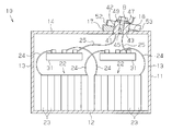
- the battery pack 10 has a case 11.
- a plurality of battery modules 22 are accommodated in the case 11.
- the case 11 includes a bottom plate 12, a side wall 13 standing from the periphery of the bottom plate 12, and a top plate 14 that closes an opening surrounded by the side wall 13.
- the case 11 has a terminal block 17 provided on the outer surface of the top plate 14 (the upper surface of the case 11).
- the terminal block 17 has a triangular shape in a side view, that is, a triangular shape in a cross section taken along line 2-2 in FIG. 1, and has a terminal block inclined surface 18 inclined downward on the upper surface thereof.
- the terminal block inclined surface 18 is inclined with respect to the horizontal plane.
- the terminal block 17 is configured such that the terminal block inclined surface 18 is inclined with respect to the horizontal plane in a state where the battery pack 10 is installed.
- the terminal block 17 is made of resin.
- the terminal block inclined surface 18 is inclined with respect to the outer surface of the top plate 14 (the upper surface of the case 11) and is inclined toward one end of the top plate 14.
- each battery module 22 has a plurality of battery cells 23.
- each battery cell 23 has a positive electrode 26 and a negative electrode 27.
- a power line 24 is connected to the battery cells 23 positioned at both ends of the battery module 22 in the direction in which the battery cells 23 are arranged. Specifically, among the battery cells 23 at both ends of the battery module 22, the power line 24 is connected to the positive electrode 26 of one battery cell 23 and the negative electrode 27 of the other battery cell 23.
- Two connection bases 31 are accommodated in the case 11. The same polarity power lines 24 connected to the plurality of battery modules 22 are electrically connected to the same connection base 31.
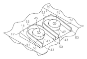
- a through hole 41 is formed in the top plate 14, and a through hole 42 communicating with the through hole 41 is formed in the terminal block 17.
- Columnar terminals 43 are inserted into the through holes 41 and 42 that communicate with each other.
- the terminal 43 is formed with a terminal hole 45 extending in the axial direction and communicating between the inside of the case 11 and the outside of the case 11, and a screw is formed on the inner peripheral surface of the terminal hole 45.
- the battery pack 10 has two terminals 43.
- the lower end of the terminal 43 is exposed in the case 11.
- the upper end of the terminal 43 protrudes outside the case 11 through the terminal block inclined surface 18.
- the upper end of the terminal 43 protrudes upward from the terminal block inclined surface 18.
- the terminal block inclined surface 18 is in contact with the outer peripheral surface of the terminal 43.
- the upper end of the terminal 43 (the upper surface of the terminal 43) is an inclined surface that is inclined downward (in other words, inclined with respect to the horizontal plane) in a state where the battery pack 10 is installed. Functions as a bonding surface to be bonded.
- the upper end of the terminal 43 will be described as the joint surface 47.
- the joint surface 47 is inclined with respect to the outer surface of the top plate 14 (the upper surface of the case 11) and is inclined so as to be lowered toward one end of the top plate 14.
- the bonding surface 47 of the terminal 43 is connected to a wiring 48 as a connecting member that electrically connects the terminal 43 to a device that receives power supply from the plurality of battery cells 23.
- the wiring 48 has an annular plate-like connection portion 49.
- the wire 48 is joined to the terminal 43 by screwing the bolt B passing through the connection portion 49 into the terminal hole 45 of the terminal 43.
- a power line 25 that electrically connects one connection base 31 and the terminal 43 is connected to the lower end of each terminal 43, and each terminal 43 and a plurality of battery cells 23 (battery modules 22) are connected to the power line 24. 25 and one of the connection bases 31 are electrically connected.
- the terminal block inclined surface 18 is provided with a rib 51 having a U-shape in plan view as a standing portion.
- the rib 51 is erected from the terminal block inclined surface 18 and surrounds each terminal 43.
- the rib 51 is open at a portion located below the terminal 43 in the terminal block inclined surface 18.
- the rib 51 has a base portion 52 at a portion located above the terminal 43 in the terminal block inclined surface 18. That is, the rib 51 has the base 52 upstream of the terminal 43 in the flow direction of the liquid flowing through the terminal block inclined surface 18.
- a pair of extending portions 53 extend in the inclination direction of the terminal block inclined surface 18 so as to sandwich the terminal 43 from the base portion 52.
- the operation of the battery pack 10 of this embodiment will be described.
- liquid for example, condensed water
- the liquid flows on the terminal block inclined surface 18.
- the liquid generated outside the region surrounded by the ribs 51 on the terminal block inclined surface 18 is prevented from adhering to the terminals 43 by the ribs 51. Further, since the liquid generated in the region surrounded by the ribs 51 flows through the terminal block inclined surface 18, the retention of the liquid on the terminal block inclined surface 18 is suppressed.
- the following effects can be obtained. (1) Since the joint surface 47 of the terminal 43 with the connection member (wiring 48) is inclined, the liquid is unlikely to stay on the joint surface 47 of the terminal 43, and corrosion of the joint surface 47 by the liquid is suppressed. For this reason, an increase in contact resistance between the terminal 43 and the connection member due to corrosion of the joint surface 47 is suppressed, and power loss is unlikely to increase. For this reason, for example, when the battery pack 10 is mounted on a vehicle, the travel distance of the vehicle is unlikely to be shortened.
- the rib 51 prevents the liquid flowing from the portion above the terminal 43 on the terminal block inclined surface 18 from adhering to the terminal 43. For this reason, it is further suppressed that the terminal 43 corrodes. In addition, since the rib 51 that reinforces the terminal block 17 is also used as a standing portion that prevents the liquid from adhering to the terminal 43, the number of parts can be reduced.
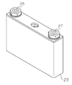
- the secondary battery 61 includes a battery case 62 and an electrode assembly 63 accommodated in the battery case 62.
- the battery case 62 includes a bottomed box-shaped main body 64 that houses the electrode assembly 63, and a plate-shaped lid 65 that closes the opening of the main body 64.
- the lid 65 is provided with two terminals 66 (a positive terminal and a negative terminal).
- the electrode assembly 63 has a plurality of positive and negative electrodes stacked.
- the terminal 66 is electrically connected to the electrode assembly 63 via the conductive member 69.
- the lid portion 65 has two through holes 67 that penetrate in the thickness direction of the lid portion 65. An insulating ring 68 is inserted into each through hole 67.
- the terminal 66 has a cylindrical shaft portion 71 that is inserted into the through hole 67 (insulating ring 68) and protrudes from the battery case 62 to the outside of the battery case 62.
- the shaft portion 71 has a threaded portion 72 in which a screw is formed on the outer peripheral surface of a tip region (an end region protruding outside the battery case 62). Further, at the base end of the shaft portion 71 (the end portion on the side opposite to the tip of the shaft portion 71), a drop prevention portion 73 larger than the diameter of the through hole 67 is provided.
- the nut N1 is screwed to the screw portion 72 of the shaft portion 71.
- the terminal 66 is fixed to the lid portion 65.
- the tip surface 74 of the shaft portion 71 is an inclined surface that is inclined downward. Since connection members such as wiring and bus bars are connected to the distal end surface 74, the distal end surface 74 becomes a bonding surface.
- the tip surface 74 is inclined with respect to the horizontal plane. More specifically, the terminal 66 is configured such that the tip surface 74 is inclined with respect to the horizontal plane in a state where the secondary battery 61 is installed.
- the tip surface 74 is inclined with respect to the outer surface of the lid portion 65 (the upper surface of the battery case 62).
- the terminal block inclined surface 18 may not be provided. That is, the terminal 43 may be provided on a horizontal flat surface, in other words, on a flat surface parallel to the upper surface of the case 11.
- the rib 51 may be only the base 52. Even in this case, the base 52 provided in the portion of the terminal block inclined surface 18 above the terminal 43 prevents the liquid from adhering to the terminal 43. Further, the rib 51 may not be provided.
- the connecting member may be a bus bar.
- the power line 24 may be directly connected to the terminal 43 without providing the connection base 31.
- the terminal block 17 may not be made of resin. For example, it may be made of metal coated with an insulating member.
- the terminal block 17 has the terminal block inclined surface 18, but the top plate 14 of the case 11 may be provided with an inclined surface. Further, the terminal block inclined surface 18 may be provided outside the case 11 and may not be provided in the case 11.
- the joint surface 47 of only one of the two terminals 43 of the first embodiment may be an inclined surface. Moreover, it is good also considering only any one front end surface 74 as an inclined surface among the two terminals 66 of 2nd Embodiment.
- connection base 31 may be integrated with the case 11.
- the plurality of connection bases 31 may be integrated.
Landscapes
- Chemical & Material Sciences (AREA)
- Chemical Kinetics & Catalysis (AREA)
- Electrochemistry (AREA)
- General Chemical & Material Sciences (AREA)
- Battery Mounting, Suspending (AREA)
- Connection Of Batteries Or Terminals (AREA)
Applications Claiming Priority (2)
| Application Number | Priority Date | Filing Date | Title |
|---|---|---|---|
| JP2013-201930 | 2013-09-27 | ||
| JP2013201930A JP6206042B2 (ja) | 2013-09-27 | 2013-09-27 | 電池パック |
Publications (1)
| Publication Number | Publication Date |
|---|---|
| WO2015045966A1 true WO2015045966A1 (ja) | 2015-04-02 |
Family
ID=52743107
Family Applications (1)
| Application Number | Title | Priority Date | Filing Date |
|---|---|---|---|
| PCT/JP2014/074441 Ceased WO2015045966A1 (ja) | 2013-09-27 | 2014-09-16 | 電池パック及び二次電池 |
Country Status (2)
| Country | Link |
|---|---|
| JP (1) | JP6206042B2 (enExample) |
| WO (1) | WO2015045966A1 (enExample) |
Cited By (4)
| Publication number | Priority date | Publication date | Assignee | Title |
|---|---|---|---|---|
| CN106486614A (zh) * | 2015-08-27 | 2017-03-08 | 三星Sdi株式会社 | 可再充电电池 |
| WO2017208804A1 (ja) * | 2016-05-31 | 2017-12-07 | パナソニックIpマネジメント株式会社 | 端子接続構造、電池積層体及び端子接続構造の形成方法 |
| WO2022102700A1 (ja) * | 2020-11-12 | 2022-05-19 | 住友電装株式会社 | 端子台 |
| WO2022102699A1 (ja) * | 2020-11-12 | 2022-05-19 | 住友電装株式会社 | 端子台 |
Families Citing this family (1)
| Publication number | Priority date | Publication date | Assignee | Title |
|---|---|---|---|---|
| JP7359682B2 (ja) * | 2019-12-20 | 2023-10-11 | ファナック株式会社 | バスバーを有するモータ駆動装置 |
Citations (5)
| Publication number | Priority date | Publication date | Assignee | Title |
|---|---|---|---|---|
| JPS60193666U (ja) * | 1984-05-31 | 1985-12-23 | 株式会社ユアサコーポレーション | 蓄電池 |
| JP2011233367A (ja) * | 2010-04-27 | 2011-11-17 | Toyota Motor Corp | 接続ユニットおよび蓄電装置 |
| JP2012079456A (ja) * | 2010-09-30 | 2012-04-19 | Mitsubishi Heavy Ind Ltd | 組電池 |
| JP2012119156A (ja) * | 2010-11-30 | 2012-06-21 | Sanyo Electric Co Ltd | 組電池及びこれを装備する電動車両 |
| US20130269978A1 (en) * | 2012-04-12 | 2013-10-17 | Robert Bosch Gmbh | Battery module |
Family Cites Families (1)
| Publication number | Priority date | Publication date | Assignee | Title |
|---|---|---|---|---|
| JPH11149935A (ja) * | 1997-11-18 | 1999-06-02 | Japan Storage Battery Co Ltd | 蓄電池 |
-
2013
- 2013-09-27 JP JP2013201930A patent/JP6206042B2/ja not_active Expired - Fee Related
-
2014
- 2014-09-16 WO PCT/JP2014/074441 patent/WO2015045966A1/ja not_active Ceased
Patent Citations (5)
| Publication number | Priority date | Publication date | Assignee | Title |
|---|---|---|---|---|
| JPS60193666U (ja) * | 1984-05-31 | 1985-12-23 | 株式会社ユアサコーポレーション | 蓄電池 |
| JP2011233367A (ja) * | 2010-04-27 | 2011-11-17 | Toyota Motor Corp | 接続ユニットおよび蓄電装置 |
| JP2012079456A (ja) * | 2010-09-30 | 2012-04-19 | Mitsubishi Heavy Ind Ltd | 組電池 |
| JP2012119156A (ja) * | 2010-11-30 | 2012-06-21 | Sanyo Electric Co Ltd | 組電池及びこれを装備する電動車両 |
| US20130269978A1 (en) * | 2012-04-12 | 2013-10-17 | Robert Bosch Gmbh | Battery module |
Cited By (14)
| Publication number | Priority date | Publication date | Assignee | Title |
|---|---|---|---|---|
| CN106486614B (zh) * | 2015-08-27 | 2021-07-09 | 三星Sdi株式会社 | 可再充电电池 |
| CN106486614A (zh) * | 2015-08-27 | 2017-03-08 | 三星Sdi株式会社 | 可再充电电池 |
| CN109155387B (zh) * | 2016-05-31 | 2022-07-08 | 松下知识产权经营株式会社 | 端子连接构造、电池层叠体以及端子连接构造的形成方法 |
| WO2017208804A1 (ja) * | 2016-05-31 | 2017-12-07 | パナソニックIpマネジメント株式会社 | 端子接続構造、電池積層体及び端子接続構造の形成方法 |
| CN109155387A (zh) * | 2016-05-31 | 2019-01-04 | 松下知识产权经营株式会社 | 端子连接构造、电池层叠体以及端子连接构造的形成方法 |
| JPWO2017208804A1 (ja) * | 2016-05-31 | 2019-03-28 | パナソニックIpマネジメント株式会社 | 端子接続構造、電池積層体及び端子接続構造の形成方法 |
| US11158911B2 (en) | 2016-05-31 | 2021-10-26 | Panasonic Intellectual Property Management Co., Ltd. | Terminal connection structure, battery stack body, and method for forming terminal connection structure |
| WO2022102700A1 (ja) * | 2020-11-12 | 2022-05-19 | 住友電装株式会社 | 端子台 |
| JP2022077892A (ja) * | 2020-11-12 | 2022-05-24 | 住友電装株式会社 | 端子台 |
| JP2022077891A (ja) * | 2020-11-12 | 2022-05-24 | 住友電装株式会社 | 端子台 |
| WO2022102699A1 (ja) * | 2020-11-12 | 2022-05-19 | 住友電装株式会社 | 端子台 |
| JP7380529B2 (ja) | 2020-11-12 | 2023-11-15 | 住友電装株式会社 | 端子台 |
| JP7380528B2 (ja) | 2020-11-12 | 2023-11-15 | 住友電装株式会社 | 端子台 |
| US12374812B2 (en) | 2020-11-12 | 2025-07-29 | Sumitomo Wiring Systems, Ltd. | Terminal block |
Also Published As
| Publication number | Publication date |
|---|---|
| JP2015069778A (ja) | 2015-04-13 |
| JP6206042B2 (ja) | 2017-10-04 |
Similar Documents
| Publication | Publication Date | Title |
|---|---|---|
| US9209447B2 (en) | Secondary battery module | |
| WO2015045966A1 (ja) | 電池パック及び二次電池 | |
| US9318734B2 (en) | Bimetal buss bar assembly | |
| US9627151B2 (en) | Electrical storage module | |
| WO2020135005A1 (zh) | 电池包和车辆 | |
| JP5009030B2 (ja) | 組電池、単電池及び電池パック | |
| US20100216008A1 (en) | Secondary battery module | |
| JP5869789B2 (ja) | ヒューズユニット | |
| US20070184711A1 (en) | Electrical module | |
| JPWO2019131359A1 (ja) | 電池モジュール | |
| CN105702904A (zh) | 电池组 | |
| JP6177882B2 (ja) | 電池パック及び締結構造体 | |
| JP5926090B2 (ja) | 電圧検出用端子の接続構造 | |
| CN110224104B (zh) | 电池的负极柱、电池的盖板组件、电池和电动汽车 | |
| JP2013021327A (ja) | エネルギー貯蔵体ケース及びそれを含むエネルギー貯蔵装置 | |
| CN203950862U (zh) | 一种动力电池连接件及其动力电池组 | |
| US8969727B2 (en) | Battery module | |
| JP2014175152A (ja) | 電池モジュール | |
| ES2424168T3 (es) | Batería | |
| JP6345089B2 (ja) | 蓄電装置 | |
| CN106068570B (zh) | 蓄电模块 | |
| KR20190016239A (ko) | 배터리 모듈 | |
| JP5790079B2 (ja) | 放電抵抗固定構造 | |
| CN107204240A (zh) | 电力变换装置的电容器连接构件以及电容器组的连接方法 | |
| US20200403208A1 (en) | Bus bar module |
Legal Events
| Date | Code | Title | Description |
|---|---|---|---|
| 121 | Ep: the epo has been informed by wipo that ep was designated in this application |
Ref document number: 14848336 Country of ref document: EP Kind code of ref document: A1 |
|
| NENP | Non-entry into the national phase |
Ref country code: DE |
|
| 122 | Ep: pct application non-entry in european phase |
Ref document number: 14848336 Country of ref document: EP Kind code of ref document: A1 |