WO2015045925A1 - 加熱処理装置及び加熱処理方法 - Google Patents
加熱処理装置及び加熱処理方法 Download PDFInfo
- Publication number
- WO2015045925A1 WO2015045925A1 PCT/JP2014/074305 JP2014074305W WO2015045925A1 WO 2015045925 A1 WO2015045925 A1 WO 2015045925A1 JP 2014074305 W JP2014074305 W JP 2014074305W WO 2015045925 A1 WO2015045925 A1 WO 2015045925A1
- Authority
- WO
- WIPO (PCT)
- Prior art keywords
- heat treatment
- heat
- unit
- treatment head
- light source
- Prior art date
- Legal status (The legal status is an assumption and is not a legal conclusion. Google has not performed a legal analysis and makes no representation as to the accuracy of the status listed.)
- Ceased
Links
Images



Classifications
-
- B—PERFORMING OPERATIONS; TRANSPORTING
- B09—DISPOSAL OF SOLID WASTE; RECLAMATION OF CONTAMINATED SOIL
- B09B—DISPOSAL OF SOLID WASTE NOT OTHERWISE PROVIDED FOR
- B09B3/00—Destroying solid waste or transforming solid waste into something useful or harmless
- B09B3/50—Destroying solid waste or transforming solid waste into something useful or harmless involving radiation, e.g. electro-magnetic waves
-
- B—PERFORMING OPERATIONS; TRANSPORTING
- B09—DISPOSAL OF SOLID WASTE; RECLAMATION OF CONTAMINATED SOIL
- B09B—DISPOSAL OF SOLID WASTE NOT OTHERWISE PROVIDED FOR
- B09B2101/00—Type of solid waste
- B09B2101/35—Asbestos
Definitions
- the present invention relates to a heat treatment apparatus and a heat treatment method for performing heat treatment by irradiating an object to be heated with light from a heat ray light source.
- the method for detoxifying asbestos described in Patent Document 1 describes that asbestos is made harmless by irradiating light from a heat ray light source as a convergent light beam or the like with an optical lens to the asbestos coating.
- Patent Documents 2 and 3 related to the inventors of the present application are a method of condensing light from a heat ray light source with a reflecting mirror having a substantially elliptical cross section and irradiating the asbestos coating. .
- This method is not only low in equipment cost but also very energy efficient and is the most suitable method for in situ melting.
- the present invention has been made in view of the above circumstances, and an object thereof is to provide a heat treatment apparatus or the like that can perform heat treatment with high efficiency and low cost and that does not deform the object to be heated.
- a heat treatment apparatus comprises: Heating the object to be heated while moving a heat treatment head having a plurality of condensing heating units composed of a heat ray light source and a reflecting mirror for collecting light from the heat ray light source along the surface of the object to be heated
- a heat treatment device for The heat treatment head comprises a unit row in which two or more condensing heating units are arranged in a direction along the moving direction of the heat treatment head, Independently supplying power to each of the heat ray light sources of the two or more condensing heating units constituting the unit row, It is characterized by that.
- the unit rows are arranged in two or more rows in a direction perpendicular to the moving direction of the heat treatment head,
- the condensing and heating units constituting each unit row are arranged one by one on the same straight line perpendicular to the moving direction of the heat treatment head, You may make it supply the same electric power for every condensing heating unit on the said same straight line.
- the power supplied to the front condensing heating unit in the direction along the moving direction of the heat treatment head is greater than that of the rear condensing heating unit. You may make it become lower than supply electric power.
- the heat ray light source may be at least one light source of a halogen lamp, a xenon lamp, and a metal halide lamp that emit light with a power of less than 3 kW.
- An air discharge section that discharges air to the periphery of the heat ray light source and the inner surface of the reflecting mirror, an air suction section that sucks air between the condensing heating unit and the heated object, and the air suction section You may make it further have a gas removal apparatus which removes predetermined gas from the performed air, and a circulation fan which circulates the air which permeate
- the heat treatment method includes: A heat treatment head moving step for moving a heat treatment head, in which a plurality of condensing heating units composed of a heat ray light source and a reflecting mirror for condensing light from the heat ray light source, are moved along the surface of the object to be heated; A heating step of condensing the light of the heat ray light source of each of the condensing heating units and irradiating the object to be heated to heat the object to be heated,
- the heat treatment head comprises a unit row in which two or more condensing heating units are arranged in a direction along the moving direction of the heat treatment head, Independently supplying power to each of the heat ray light sources of the two or more condensing heating units constituting the unit row, It is characterized by that.
- high-efficiency and low-cost heat treatment can be performed, and deformation of the heated object can be avoided.
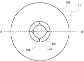
- FIG. 3 is a front view of the condensing heating unit according to Embodiment 1.
- FIG. 2 is a cross-sectional view of a condensing heating unit according to Embodiment 1.
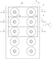
- FIG. 3 is a front view of the heat treatment head according to Embodiment 1.
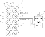
- FIG. 6 is a diagram for explaining a heat treatment head according to a second embodiment.
- FIG. 10 is a diagram for explaining air circulation of the heat treatment head according to the second embodiment.
- the heat treatment apparatus 1 is an apparatus that renders asbestos harmless by heat-treating the heated object 50 containing asbestos in the surface coating.
- the heated object 50 is, for example, a wall or ceiling of a building.
- the heat treatment apparatus 1 includes a heat treatment head 10 that irradiates the object to be heated 50 with heat ray light, a robot 20 that moves the heat treatment head 10 along the surface of the object to be heated 50, and the robot 20.
- the robot 20 is any conventionally known working robot.
- the robot 20 includes a base 20A, a Z stage 20B, and a rotating unit 20C.
- the base 20A fixes the Z stage 20B to the carriage 30.
- the Z stage 20B moves the rotating unit 20C up and down in the vertical direction.
- the rotating unit 20C has a rotation axis R perpendicular to the extending direction of the Z stage 20B, and rotates the heat treatment head 10 fixed to the rotating unit 20C.
- the robot 20 includes motors for driving the Z stage 20B and the rotating unit 20C, and the operation of each motor is controlled by the control unit 40. That is, the height and orientation of the heat treatment head 10 with respect to the heated object 50 can be changed by changing the position of the Z stage 20B in the vertical direction and the rotation amount of the rotating unit 20C under the control of the control unit 40. it can.
- the carriage 30 includes a motor controlled by the control unit 40 and is self-propelled by the operation of the motor. It moves to the immediate vicinity of the heated body 50 and moves in the horizontal direction (XY direction) along the heated body 50.
- the control unit 40 includes an arithmetic processing unit, an internal memory, a communication unit, and the like, and controls driving of the heating processing head 10, the robot 20, and the carriage 30 based on an operation input by an operator. The operator's operation input is made possible from a place away from the heat treatment site.
- the control unit 40 moves the cart 30 to the target 50 nearest to the heated object 50 based on the input of the operator's control command. Free-run to the position and stop.
- the control unit 40 controls the robot 20 and the carriage 30 so that the heat treatment head 10 faces the surface of the object 50 to be heated. Move to the required position.
- the control unit 40 controls the heat treatment head 10, the robot 20, and the carriage 30 to irradiate light from the heat treatment head 10 and heat treatment head. 10 is controlled to move along the surface of the heated object 50.
- the moving direction of the heat treatment head 10 is defined as the S direction.
- the control unit 40 first controls the rotation unit 20C to make the heat treatment head 10 face the wall surface. Then, light irradiation from the heat treatment head 10 is started, and the carriage 30 is controlled to move on the floor in parallel with the surface of the wall, so that the heat treatment head 10 is moved in the horizontal direction along the surface of the wall. Translate in the X direction. That is, here, the S direction and the X direction are parallel.
- the Z stage 20B is controlled to cause the heat treatment head 10 to be translated in the vertical direction by a predetermined distance. Thereafter, by controlling the carriage 30, the heat treatment head 10 is translated in the horizontal direction ( ⁇ X direction).
- the control unit 40 controls the rotation unit 20C to rotate so that the heat treatment head 10 faces the ceiling surface. Then, light irradiation from the heat treatment head 10 is started, and the carriage 30 is controlled to move in one predetermined direction on the floor (XY plane), whereby the heat treatment head 10 is moved to the ceiling surface. Translate along That is, here, the predetermined moving direction of the carriage 30 is the S direction. When reaching the end of the ceiling, the carriage 30 is controlled to translate the heat treatment head 10 by a predetermined distance in a direction perpendicular to the S direction. Thereafter, by controlling the carriage 30, the heat treatment head 10 is translated in the ( ⁇ S) direction. By repeating the above operation, the entire surface of the ceiling of the object to be heated 50 is heated.
- the heat treatment head 10 has a configuration in which a plurality of condensing heating units 11 as shown in FIG. 2 are arranged.
- the condensing heating unit 11 includes a heat linear light source 101 and a reflecting mirror 102 that condenses the light from the heat linear light source 101.
- a fixture 103 including a socket for supplying power to the heat ray light source 101 is supported by a support 104 with respect to the reflecting mirror 102.
- the heat ray light source 101 includes, for example, a halogen lamp, a xenon lamp, a metal halide lamp, or the like. Considering the thermal efficiency indicating the temperature rise of the surface of the object to be heated 50 with respect to the power supplied to the heat linear light source 101, the power supplied to the heat linear light source 101 is preferably less than 3 kW.
- the reflecting mirror 102 has a shape substantially coinciding with a part of the surface of the spheroid whose major axis is the rotation axis.
- the heat ray light source 101 is located at one of the focal points of the spheroid, and the light of the heat ray light source 101 is reflected by the reflecting mirror 102 and condensed at the other focus position.
- the inner surface of the reflecting mirror 102 is subjected to metal plating or the like, and is processed so as to increase its reflection efficiency.
- FIG. 2A is a front view of the reflecting mirror 102 as viewed from the focal side where the heat ray light source 101 is not located.
- the outer edge of the reflecting mirror 102 is substantially circular with the major axis of the spheroid as the center.
- 2B is a cross-sectional view taken along the line a-a ′ of FIG. 2A.
- the cross section of the reflecting mirror 102 has a part of an ellipse whose focal point is the position of the heat ray light source 101, and the light reflected by the reflector 102. Is collected at another focal point F of the ellipse. Therefore, the heated object 50 determines the position of the heat treatment head 10 so as to be positioned on a plane passing through the focal point F and perpendicular to the long axis of the ellipse.
- the heat treatment head 10 includes a plurality of condensing heating units 11 arranged on the same plane as shown in FIG. This arrangement is composed of unit rows in which two or more condensing heating units 11 are arranged in the S direction, which is the direction in which the heat treatment head 10 moves when the object to be heated 50 is heat-treated. One or more unit rows are arranged in a direction perpendicular to the S direction.
- FIG. 3 shows the heat treatment head 10 when two condensing heating units 11 are included in one unit row and five unit rows are arranged.
- the condensing heating unit 11 in the uppermost unit row A is the unit 11-A1 and the unit 11-A2, and the condensing heating unit 11 in the second unit row B from the top is the unit 11-B1 and the unit 11-B2.
- the condensing heating unit 11 of the third unit row C from the top is the unit 11-C1 and the unit 11-C2.
- the condensing heating units 11 included in each unit row are arranged one by one on the same straight line perpendicular to the moving direction S of the heat treatment head 10. . 3, unit 11-A1, unit 11-B1, unit 11-C1,... Are arranged on the same straight line, and unit 11-A2, unit 11-B2, unit 11-C2,. They are arranged on the same straight line.
- the power supplied to the heat linear light source 101 of each condensing heating unit is set so that the same power is supplied to each condensing heating unit 11 arranged on the same straight line. Then, the supply power of the front condensing heating unit 11 in the direction along the moving direction S of the heat treatment head 10 is set to be lower than that of the rear condensing heating unit 11. That is, in FIG. 3, the power supplied to the units 11-A1, 11-B1, and 11-C1 is made lower than the power supplied to the units 11-A2, 11-B2, and 11-C2. .
- the supply power of each of the units 11-A1, 11-B1, and 11-C1 is 200 W
- the supply power of each of the units 11-A2, 11-B2, and 11-C2 is 1 kW.
- the condensing heating unit 11 included in each unit row passes through the same portion of the object to be heated 50. Therefore, the first condensing and heating unit 11 first volatilizes the component having the volatility characteristic by irradiating with low power and low power light and preliminarily heating and drying. Thereafter, the second condensing and heating unit 11 irradiates high power light with high power to dissolve and solidify asbestos. That is, in the case of the unit row A, the unit 11-A1 volatilizes, and the unit 11-A2 dissolves asbestos.
- the arrangement interval (for example, the distance between the centers of the units 11-A1 and 11-A2) of the two or more condensing heating units 11 included in each unit row is determined by the moving speed of the heat treatment head 10 and the condensing heating unit 11
- the optimum distance is set based on the power supply. For example, when the diameter of the circle at the outer edge of the reflecting mirror 102 of the condensing heating unit 11 is 5 cm, the arrangement interval of two or more condensing heating units 11 included in each unit row is preferably 5 to 10 cm.
- the arrangement interval (for example, the distance between the centers of the units 11-A1 and 11-B1) of the condensing heating units 11 arranged on the same straight line is the optimum distance based on the power supplied to each condensing heating unit 11 and the like.
- the arrangement interval of the condensing heating units 11 arranged on the same straight line is preferably 5 to 10 cm.
- the heat treatment head 10 having the above-described configuration first condenses the light of the heat ray light source 101 while translating along the surface of the object to be heated 50 in the S direction, and irradiates the object to be heated 50. It moves to the end of the heating body 50. At the end, the heat treatment head 10 is translated in the direction perpendicular to the S direction by the width of the irradiated portion.
- the power supplied to the heat ray light source 101 of the condensing heating unit 11 is switched in each unit row. For example, if the supply power of the unit 11-A1 is 200 W and the supply power of the unit 11-A2 is 1 kW during movement in the S direction, the supply power of the unit 11-A1 is 1 kW, and the supply power of the unit 11-A2 Is changed to 200W. Then, the light to be heated 50 is condensed and irradiated to the object to be heated 50 while the heat treatment head 10 is translated in the ( ⁇ S) direction.
- the heat treatment apparatus 1 first irradiates the same portion of the object to be heated 50 with the low-power (for example, 200 W) heat ray light source 101, and the second time the high-power (for example, 1 kW). It was made to irradiate in two steps, such as irradiating with the heat ray light source 101. For this reason, a volatile component can be reduced at the 1st time and temperature can be raised efficiently by the 2nd irradiation.
- heat ray light sources 101 such as halogen lamps, light sources of 3 kW or more are very expensive and it is difficult to ensure reliability. Therefore, by arranging a plurality of heat ray light sources 101 of less than 3 kW, the cost can be reduced. The processing speed can be increased.
- this embodiment can reduce a temperature difference by arranging a plurality of heat-linear light sources 101 of less than 3 kW, and can avoid deformation of an iron plate or the like.
- the heat processing apparatus 1 of this embodiment can heat-process with respect to the large part of the to-be-heated body 50, for example, the boundary part of a wall and a wall and the boundary part of a wall and a ceiling are heat rays.
- the light irradiated by the sexual light source 101 cannot reach and heat treatment cannot be performed sufficiently.
- only the incomplete portion of the heat treatment is cured with a curing sheet or the like, and the unfinished portion is heat-treated manually using a working glove or the like integrated with the curing sheet.
- the heat treatment apparatus 1 automatically heats the majority of the area of the object to be heated 50, and only the unfinished portion of the heat treatment of the small area is cured and heat-treated manually.
- the work burden of heat treatment by curing or manual work can be greatly reduced.
- the heat treatment head 10 formed by arranging a plurality of the condensing heating units 11 including the heat ray light source 101 and the reflecting mirror 102 moves along the surface of the object 50 to be heated.
- the heating body 50 is heat-treated.
- the heat treatment head 10 includes a unit row in which two or more condensing heating units 11 are arranged in a direction along the moving direction of the heat treatment head 10.
- the front condensing heating unit 11 in the moving direction of the heat treatment head 10 supplies power to the heat-line light source 101 from the rear condensing heating unit 11. Was lowered.
- the heat treatment head 60, the robot 20 that moves the heat treatment head 60 along the surface of the object to be heated 50, and the robot 20 are placed.
- a self-propelled cart 30 and a control unit 40 mounted on the cart 30 and controlling the light irradiation of the heat treatment head 60 and the operation of the robot 20 and the cart 30 are provided.
- the light irradiation of the heat treatment head 60 under the control of the control unit 40 and the operations of the robot 20 and the carriage 30 are the same as in the first embodiment.
- the heat treatment head 60 has a configuration in which a plurality of condensing heating units 12 are arranged as in the first embodiment. As shown in FIG. 4, the condensing heating unit 12 according to the present embodiment air-cools the inner surfaces of the heat ray light source 101 and the reflecting mirror 102 in addition to the heat ray light source 101 and the reflecting mirror 102 similar to those in the first embodiment, respectively.
- the air discharge part 121 which discharges the air for performing is provided.
- the heat treatment head 60 includes an air suction part 122 for sucking air in the vicinity of each condensing heating unit 12.
- the air inhaler 122 inhales air containing a toxic gas or the like emitted from the heated body 50 when heated by irradiating light from the heat ray light source 101.
- the toxic gas often floats upward, so the air suction part 122 is disposed above the condensing heating unit 12.
- a hemispherical air collecting device 123 may be provided as shown in FIG.
- the air sucked from the air sucking unit 122 passes through the gas removing device 62 to remove toxic gas and flow into the circulation fan 63.
- the circulation fan 63 discharges the introduced air toward the air discharge unit 121.
- the air removed from the vicinity of the condensing heating unit 12 is cleaned by the gas removing device 62 and the circulation fan 63 and then circulated, and the air is discharged to thereby collect the condensing heating unit of the heat treatment head 60. 12 is cooled.
- the air suction part 122 is provided in the vicinity of the condensing heating unit 12 of the heat treatment head 60, and the air sucked from the air suction part 122 and permeated through the gas removal device 62 is circulated.
- the fan 63 is circulated and discharged from the air discharge unit 121.
- the inside of the heat ray light source 101 and the reflecting mirror 102 is cooled by the air discharged from the air discharge unit 121.
- the present invention moves a heat treatment head formed by arranging a plurality of condensing heating units including a heat ray light source and a reflecting mirror for collecting light from the heat ray light source along the surface of the object to be heated.
- the present invention relates to a heat treatment apparatus for heat-treating an object to be heated.
- the heat treatment head has a configuration in which unit rows in which two or more condensing heating units are arranged in a direction along the moving direction of the heat treatment head. And it decided to supply electric power independently to each of the heat ray light source of two or more condensing heating units contained in a unit row. Thereby, high-efficiency and low-cost heat treatment can be performed, and deformation of the body to be heated can be avoided.
- the heat treatment heads 10 and 60 are configured such that five unit rows each including the two condensing heating units 11 and 12 are arranged.
- the number of the condensing heating units 11 and 12 constituting the unit row may be an arbitrary number of 2 or more, and the number of the unit rows may be an arbitrary number of 1 or more.
- column may be arbitrary values less than 3 kW.
- the heat treatment apparatus 1 when the heat treatment apparatus 1 translates the heat treatment heads 10 and 60 along the heated object 50, the heat treatment apparatus 1 performs movement in the XY direction by the carriage 30 and movement by the robot 20 in the Z direction. I made it.
- the movement of the heat treatment heads 10 and 60 may be realized by any other robot.
- an X-axis or Y-axis moving rail may be installed on the carriage 30, and the Z stage 20B may move on the rail.
- the heat treatment heads 10 and 60 may be installed at the tips of the articulated arm robots fixed on the carriage 30, and the heat treatment heads 10 and 60 may be moved.
- the heat treatment heads 10 and 60 translate in the S direction to the end of the object to be heated, then translate in the direction perpendicular to the S direction, and then in the ( ⁇ S) direction.
- the power supplied to the heat ray light source 101 of the condensing heating unit 11 of each unit row is switched at the end.
- the electric power of each heat ray light source 101 can be made constant, and an inexpensive heat ray light source 101 dedicated to low power can be used.
- the air suction unit 122 is provided above the condensing heating unit 12.
- the air suction part 122 may be at an arbitrary position as long as it is in the vicinity of the condensing heating unit 12. It is preferable to determine the position of the air suction part 122 in consideration of the direction in which the toxic gas easily flows according to the positional relationship between the heat treatment head 60 and the heated object 50. Further, the number of the air suction unit 122 and the condensing heating unit 12 may be different.
Landscapes
- Health & Medical Sciences (AREA)
- General Health & Medical Sciences (AREA)
- Toxicology (AREA)
- Engineering & Computer Science (AREA)
- Environmental & Geological Engineering (AREA)
- Working Measures On Existing Buildindgs (AREA)
- Thermotherapy And Cooling Therapy Devices (AREA)
Abstract
熱線性光源(101)と反射鏡(102)からなる集光加熱ユニット(11)を複数配列してなる加熱処理ヘッド(10)が被加熱体の表面に沿って移動しながら被加熱体を加熱処理する。加熱処理ヘッド(10)は、加熱処理ヘッド(10)の移動方向に沿った方向に2以上の集光加熱ユニット(11)を並べたユニット列からなる。各ユニット列を構成する集光加熱ユニット(11)のうち、加熱処理ヘッド(10)の移動方向において前方の集光加熱ユニット(11)の方が後方の集光加熱ユニット(11)の方より熱線性光源(101)への供給電力が低くなるようにする。
Description
本発明は、熱線性光源の光を被加熱体に照射して加熱処理する加熱処理装置及び加熱処理方法に関する。
繊維状の天然鉱物群であるアスベストは、その耐熱性、耐薬品性から、膨大な量が主に建築材料として過去に使用されてきた。しかし、アスベストの粉塵を吸引後数十年たった後、肺気腫などの重篤な病気を発症することから、現在では法的にその使用を制限されている。
そして、過去にアスベストを使用した建築物を建て替え、解体等する際に、アスベストの処理が重要な問題となる。処理方法の一つとして、1500℃以上に加熱して無害化する方法があるが、アスベスト材料を剥離・除去し、大型溶融炉まで運搬する際に飛散する危険性があった。
これに対して、解体前の状態でアスベストを含有する建築材料に対して、熱線性光源の光を照射することによりアスベストを溶融させて無害化させる方法が、その安全性と、作業負担の低減により近年注目されている(例えば特許文献1乃至3)。
特許文献1に記載のアスベストの無害化方法は、アスベスト被覆に対し熱線性光源からの光を光学レンズにより収斂性光束等にして照射し、アスベストを無害化すると説明している。
また、本願の発明者らに係る特許文献2、3の加熱処理方法等は、熱線性光源からの光を略楕円形の断面を有する反射鏡で集光させアスベスト被覆に対し照射する方法である。この方法は、装置のコストが低いだけでなく、エネルギー効率が極めて高く、現場での溶融処理には最も適した方法である。
特許文献2、3に係る加熱処理方法を用いたアスベストの無害化を更に高速かつ確実にするためには、熱線性光源の出力パワーを上げ、集光性能を上げた反射鏡の設計や製造が必要となるが、これらは処理コストを上げる要因となっていた。
また、ハイパワーの熱線性光源の光を照射すると、集光した光が当たっているところとその周囲との温度差により、アスベスト被覆を施した壁等の基盤となっている鉄板などが変形することがあった。これにより、アスベストを無害化処理した壁等を継続して使用する場合に壁が変形してしまうという問題があった。
本発明は、上記実情に鑑みてなされたものであり、高効率で低コストの加熱処理が可能でかつ被加熱体が変形することのない加熱処理装置等を提供することを目的とする。
上記目的を達成するため、本発明の第1の観点に係る加熱処理装置は、
熱線性光源と前記熱線性光源からの光を集光する反射鏡からなる集光加熱ユニットを複数配列した加熱処理ヘッドを、被加熱体の表面に沿って移動させながら前記被加熱体を加熱処理する加熱処理装置であって、
前記加熱処理ヘッドは、前記加熱処理ヘッドの移動方向に沿った方向に2以上の前記集光加熱ユニットを並べたユニット列からなり、
前記ユニット列を構成する前記2以上の集光加熱ユニットの前記熱線性光源それぞれに、独立に電力を供給する、
ことを特徴とする。
熱線性光源と前記熱線性光源からの光を集光する反射鏡からなる集光加熱ユニットを複数配列した加熱処理ヘッドを、被加熱体の表面に沿って移動させながら前記被加熱体を加熱処理する加熱処理装置であって、
前記加熱処理ヘッドは、前記加熱処理ヘッドの移動方向に沿った方向に2以上の前記集光加熱ユニットを並べたユニット列からなり、
前記ユニット列を構成する前記2以上の集光加熱ユニットの前記熱線性光源それぞれに、独立に電力を供給する、
ことを特徴とする。
前記加熱処理ヘッドは、前記ユニット列が前記加熱処理ヘッドの移動方向に対して垂直の方向に2列以上配列しており、
各ユニット列を構成する前記集光加熱ユニットは、前記加熱処理ヘッドの移動方向に対して垂直な同一直線上に一つずつ配置され、
前記同一直線上の集光加熱ユニット毎に同一の電力を供給するようにしてもよい。
各ユニット列を構成する前記集光加熱ユニットは、前記加熱処理ヘッドの移動方向に対して垂直な同一直線上に一つずつ配置され、
前記同一直線上の集光加熱ユニット毎に同一の電力を供給するようにしてもよい。
前記ユニット列を構成する2以上の集光加熱ユニットのうち、前記加熱処理ヘッドの移動方向に沿った方向において前方の前記集光加熱ユニットの供給電力の方が、後方の前記集光加熱ユニットの供給電力より低くなるようにしてもよい。
前記熱線性光源は3kW未満の電力で発光させるハロゲンランプ、キセノンランプ及びメタルハライドランプの少なくとも1種類の光源であってもよい。
前記熱線性光源の周囲と前記反射鏡の内面に空気を吐出させる空気吐出部と、前記集光加熱ユニットと前記被加熱体の間の空気を吸入する空気吸入部と、前記空気吸入部が吸入した空気から所定ガスを除去するガス除去装置と、前記ガス除去装置を透過した空気を前記空気吐出部の方へ循環させる循環ファンと、を更に有するようにしてもよい。
また、本発明の第2の観点に係る加熱処理方法は、
熱線性光源と前記熱線性光源からの光を集光する反射鏡からなる集光加熱ユニットを複数配列した加熱処理ヘッドを、被加熱体の表面に沿って移動させる加熱処理ヘッド移動ステップと、
前記集光加熱ユニットそれぞれの前記熱線性光源の光を集光して前記被加熱体に照射して、前記被加熱体を加熱する加熱ステップと、を有する加熱処理方法であって、
前記加熱処理ヘッドは、前記加熱処理ヘッドの移動方向に沿った方向に2以上の集光加熱ユニットを並べたユニット列からなり、
前記ユニット列を構成する前記2以上の集光加熱ユニットの前記熱線性光源それぞれに、独立に電力を供給する、
ことを特徴とする。
熱線性光源と前記熱線性光源からの光を集光する反射鏡からなる集光加熱ユニットを複数配列した加熱処理ヘッドを、被加熱体の表面に沿って移動させる加熱処理ヘッド移動ステップと、
前記集光加熱ユニットそれぞれの前記熱線性光源の光を集光して前記被加熱体に照射して、前記被加熱体を加熱する加熱ステップと、を有する加熱処理方法であって、
前記加熱処理ヘッドは、前記加熱処理ヘッドの移動方向に沿った方向に2以上の集光加熱ユニットを並べたユニット列からなり、
前記ユニット列を構成する前記2以上の集光加熱ユニットの前記熱線性光源それぞれに、独立に電力を供給する、
ことを特徴とする。
本発明によれば、高効率で低コストの加熱処理が可能となり、被加熱体が変形することを回避することができる。
(実施形態1)
以下、本発明の実施形態1について図1乃至3を参照して詳細に説明する。
以下、本発明の実施形態1について図1乃至3を参照して詳細に説明する。
本実施形態に係る加熱処理装置1は、表面被覆にアスベストを含有する被加熱体50に対して加熱処理してアスベストを無害化する装置である。被加熱体50は、例えば、建築物の壁や天井等である。
加熱処理装置1は、被加熱体50に対して熱線性の光を照射する加熱処理ヘッド10と、加熱処理ヘッド10を被加熱体50の表面に沿って移動させるロボット20と、ロボット20を載置した自走式の台車30と、台車30上に載置し、加熱処理ヘッド10の光照射とロボット20及び台車30の作動を制御する制御部40と、を備えている。
ロボット20は従来公知の任意の作業用ロボットである。例えば、図1に示すように、ロボット20は基部20A、Zステージ20B、回転部20Cから構成される。基部20Aは台車30に対してZステージ20Bを固定している。Zステージ20Bは、回転部20Cを鉛直方向に上下動させる。回転部20Cは、Zステージ20Bの延在方向に対して垂直の回転軸Rを有し、回転部20Cに固定された加熱処理ヘッド10を回転させる。
ロボット20は、Zステージ20B、回転部20Cの駆動用のモータをそれぞれ備えており、各モータの作動は制御部40によって制御される。つまり、制御部40の制御により、Zステージ20Bの鉛直方向における位置と、回転部20Cの回転量を変化させることで、被加熱体50に対する加熱処理ヘッド10の高さ及び向きを変化させることができる。
台車30は、制御部40によって制御されるモータを備えており、モータの作動により自走する。被加熱体50の直近まで移動し、被加熱体50に沿って、水平方向(X-Y方向)に移動する。制御部40は、演算処理装置、内部メモリ、通信部等から構成され、作業者の操作入力等に基づいて、加熱処理ヘッド10、ロボット20、台車30の駆動を制御する。作業者の操作入力は、加熱処理現場から離隔した場所からも可能な構成とする。
作業者が、まず台車30の進退/停止等について所要の制御指令の操作入力を行うと、制御部40は、作業者の制御指令の入力に基づいて台車30を被加熱体50の直近の所要位置まで自走させて停止させる。その後作業者が加熱処理ヘッド10の移動について所要の制御指令の操作入力を行うと、制御部40は、ロボット20と台車30を制御することにより加熱処理ヘッド10を被加熱体50の表面に対向する所要位置に移動させる。そして作業者が加熱処理開始の制御指令の操作入力を行うと、制御部40は、加熱処理ヘッド10、ロボット20、台車30を制御することにより、加熱処理ヘッド10から光照射するとともに加熱処理ヘッド10を被加熱体50の表面に沿って移動させるように制御する。ここで、加熱処理ヘッド10の移動方向をS方向とする。
例えば、被加熱体50が鉛直方向に建てられた壁である場合には、まず制御部40は、回転部20Cを回転制御して加熱処理ヘッド10を壁面に対向させる。そして、加熱処理ヘッド10からの光照射を開始するとともに、台車30が床上を壁の表面に平行に移動するように制御することにより、加熱処理ヘッド10を、壁の表面に沿って、水平方向(X方向)に平行移動させる。つまり、ここではS方向とX方向が平行である。そして、壁の端部に到達するとZステージ20Bを制御して加熱処理ヘッド10を鉛直方向に所定距離だけ平行移動させる。その後台車30を制御することにより、加熱処理ヘッド10を水平方向(-X方向)に平行移動させる。以上の動作を繰り返すことにより被加熱体50の壁のほぼ全面を加熱処理する。
また、被加熱体50が床面に対向した天井である場合には、まず制御部40は、回転部20Cを回転制御して加熱処理ヘッド10を天井面に対向させる。そして、加熱処理ヘッド10からの光照射を開始するとともに、台車30が床上(X-Y平面)の予め定めた一方向に移動するように制御することにより、加熱処理ヘッド10を、天井の表面に沿って平行移動させる。つまり、ここでは台車30の予め定めた移動方向がS方向である。そして、天井の端部に到達すると台車30を制御して加熱処理ヘッド10をS方向に垂直な方向に所定距離だけ平行移動させる。その後台車30を制御することにより、加熱処理ヘッド10を(-S)方向に平行移動させる。以上の動作を繰り返すことにより被加熱体50の天井のほぼ全面を加熱処理する。
次に、加熱処理ヘッド10について詳細に説明する。加熱処理ヘッド10は、図2に示すような集光加熱ユニット11を複数配列した構成を有している。集光加熱ユニット11は、熱線性光源101と、熱線性光源101からの光を集光する反射鏡102を備えている。熱線性光源101への電力供給用のソケットを含む固定具103は、反射鏡102に対して支持部104により支持されている。
熱線性光源101は、例えばハロゲンランプ、キセノンランプ、メタルハライドランプ等から構成される。熱線性光源101への供給電力に対する、被加熱体50の表面の温度上昇を示す熱効率等を考慮すると、熱線性光源101への供給電力は3kW未満が望ましい。
反射鏡102は、長軸を回転軸とした回転楕円体の表面の一部に略一致する形状を有している。熱線性光源101は回転楕円体の焦点の一方に位置しており、他方の焦点の位置に熱線性光源101の光が反射鏡102で反射されて集光する。反射鏡102の内面は、金属メッキ等が施され、その反射効率を高めるように加工している。
図2Aは、反射鏡102を熱線性光源101が位置しない方の焦点側から見た前面図である。図2Aに示すように、反射鏡102の外縁は回転楕円体の長軸を中心とした略円形である。図2Bは、図2Aのa-a’線における断面図である。図2Bに示すように、反射鏡102の断面は、熱線性光源101の位置を焦点とする楕円の一部の形状を有しており、熱線性光源101の光が反射鏡102で反射した光は、楕円のもう一つの焦点Fに集光される。よって、被加熱体50は、焦点Fを通り、楕円の長軸に垂直な面上に位置するように、加熱処理ヘッド10の位置を決定する。
加熱処理ヘッド10は、図3に示すように、同一平面上に配列した複数の集光加熱ユニット11を備えている。この配列は、被加熱体50に対して加熱処理する際に加熱処理ヘッド10が移動する方向であるS方向に2以上の集光加熱ユニット11を並べたユニット列から構成される。そして、1以上のユニット列がS方向に垂直の方向に並べられている。図3は、ユニット列1列につき2つの集光加熱ユニット11を含み、ユニット列が5列配列した場合の加熱処理ヘッド10を示している。最上列のユニット列Aの集光加熱ユニット11がユニット11-A1、ユニット11-A2であり、上から2列目のユニット列Bの集光加熱ユニット11がユニット11-B1、ユニット11-B2であり、上から3列目のユニット列Cの集光加熱ユニット11がユニット11-C1、ユニット11-C2である。
ユニット列の列数が2以上の場合には、各ユニット列に含まれる集光加熱ユニット11は、加熱処理ヘッド10の移動方向Sに対して垂直な同一直線上に1つずつ配置されている。図3においては、ユニット11-A1、ユニット11-B1、ユニット11-C1・・・が同一の直線上に配置され、ユニット11-A2、ユニット11-B2、ユニット11-C2、・・・が同一の直線上に配置されている。
各集光加熱ユニットの熱線性光源101への供給電力は、同一の直線上に配置された集光加熱ユニット11毎に同一の電力を供給するように設定する。そして、加熱処理ヘッド10の移動方向Sに沿った方向に向かって前方の集光加熱ユニット11の方が後方の集光加熱ユニット11よりも供給電力が低くなるようにする。つまり図3において、ユニット11-A1、ユニット11-B1、ユニット11-C1の供給電力の方が、ユニット11-A2、ユニット11-B2、ユニット11-C2の供給電力よりも低くなるようにする。例えば、ユニット11-A1、ユニット11-B1、ユニット11-C1の供給電力をそれぞれ200Wとし、ユニット11-A2、11-B2、ユニット11-C2の供給電力をそれぞれ1kWとする。
加熱処理ヘッド10はS方向に一定速度で移動するため、各ユニット列に含まれる集光加熱ユニット11は、被加熱体50の同一箇所を通過することになる。よって、まず1つ目の集光加熱ユニット11が、低い電力で低パワーの光を照射して予備的に加熱して乾燥させることにより、揮発特性を有する成分を揮発させる。その後2つ目の集光加熱ユニット11が高い電力で高パワーの光を照射して、アスベストを溶解して固化させる。つまり、ユニット列Aの場合、ユニット11-A1により揮発させ、ユニット11-A2によりアスベストを溶解させる。
各ユニット列に含まれる2以上の集光加熱ユニット11の配列間隔(例えばユニット11-A1とユニット11-A2の中心間距離)は、加熱処理ヘッド10の移動速度と各集光加熱ユニット11の供給電力等に基づいて最適な距離とする。例えば、集光加熱ユニット11の反射鏡102の外縁の円の直径が5cmであった場合、各ユニット列に含まれる2以上の集光加熱ユニット11の配列間隔は、5~10cmが好ましい。
同一の直線上に配置された集光加熱ユニット11の配列間隔(例えばユニット11-A1とユニット11-B1の中心間距離)は、各集光加熱ユニット11の供給電力等に基づいて最適な距離とする。例えば、集光加熱ユニット11の反射鏡の外縁の円の直径が5cmであった場合、同一の直線上に配置された集光加熱ユニット11の配列間隔は、5~10cmが好ましい。
以上のような構成の加熱処理ヘッド10が、被加熱体50の表面に沿って、まずS方向に平行移動しながら熱線性光源101の光を集光させて被加熱体50に照射し、被加熱体50の端部まで移動する。端部では照射部分の幅分だけS方向に垂直の方向に加熱処理ヘッド10が平行移動する。
その後、加熱処理ヘッド10の移動方向が180度反転し(-S)方向となるため、集光加熱ユニット11の熱線性光源101の供給電力を、各ユニット列内で入れ替える。例えば、S方向移動中にユニット11-A1の供給電力が200Wでユニット11-A2の供給電力が1kWだった場合には、ユニット11-A1の供給電力を1kWとし、ユニット11-A2の供給電力を200Wに変更する。そして、加熱処理ヘッド10を、(-S)方向に平行移動させながら熱線性光源101の光を集光させて被加熱体50に照射する。
この動作を繰り返すことにより、被加熱体50のほぼ全面に対して加熱処理を施し、被加熱体50に含まれるアスベストを溶解固化して無害化する。
本実施形態では、加熱処理装置1は、被加熱体50の同一の箇所に対して、最初に低電力(例えば200W)の熱線性光源101で照射し、2回目に高電力(例えば1kW)の熱線性光源101で照射するというように、2段階で照射するようにした。このため、1回目で揮発成分を減少させて2回目の照射で効率的に温度を上昇させることができる。ハロゲンランプ等の熱線性光源101のうち、3kW以上の光源は非常に高価で信頼性の確保も困難であるため、3kW未満の熱線性光源101を複数配列する構成にすることで、コストも低減させることができ、処理スピードも上げることができる。
また、3kW以上の光源は、照射する光パワーも非常に高いため、熱線性光源101から直接照射される中心部分の温度上昇が非常に早く、その周囲との温度差が大きくなる。このため、アスベスト被覆を施した壁等の基盤となっている鉄板等が変形してしまうことがあった。これに対し、本実施形態は、3kW未満の熱線性光源101を複数配列する構成にすることで温度差を低減させることができ、鉄板等の変形を回避することができる。
なお、本実施形態の加熱処理装置1は、被加熱体50の大部分に対して加熱処理することが可能であるが、例えば、壁と壁の境界部分、壁と天井の境界部分は、熱線性光源101が照射する光が到達できず、十分に加熱処理できない。このような場合には、加熱処理の未完了部分のみを養生シート等で養生し、養生シートと一体化した作業用手袋等を用いて、手作業で未完了部分の加熱処理を行う。このように、加熱処理装置1が被加熱体50の大部分の面積を自動で加熱処理をし、小面積の加熱処理の未完了部分のみを養生して手作業で加熱処理する。これにより、養生や手作業による加熱処理の作業負担も大幅に軽減することができる。
以上説明したように、本実施形態において、熱線性光源101と反射鏡102からなる集光加熱ユニット11を複数配列してなる加熱処理ヘッド10が被加熱体50の表面に沿って移動しながら被加熱体50を加熱処理する。加熱処理ヘッド10は、加熱処理ヘッド10の移動方向に沿った方向に2以上の集光加熱ユニット11を並べたユニット列からなる。各ユニット列を構成する集光加熱ユニット11のうち、加熱処理ヘッド10の移動方向において前方の集光加熱ユニット11の方が後方の集光加熱ユニット11の方より熱線性光源101への供給電力が低くなるようにした。これにより、高効率で低コストの加熱処理が可能でかつ被加熱体50が変形することも回避することが可能となる。
(実施形態2)
以下、本発明の実施形態2について図4、5を参照して詳細に説明する。
以下、本発明の実施形態2について図4、5を参照して詳細に説明する。
本実施形態に係る加熱処理装置1は、実施形態1と同様に、加熱処理ヘッド60と、加熱処理ヘッド60を被加熱体50の表面に沿って移動させるロボット20と、ロボット20を載置した自走式の台車30と、台車30上に載置し、加熱処理ヘッド60の光照射とロボット20及び台車30の作動を制御する制御部40と、を備えている。制御部40の制御による加熱処理ヘッド60の光照射とロボット20及び台車30の動作等は実施形態1と同様である。
加熱処理ヘッド60は、実施形態1と同様に、複数の集光加熱ユニット12が配列された構成を有している。本実施形態に係る集光加熱ユニット12は、図4に示すように、それぞれ実施形態1と同様の熱線性光源101、反射鏡102に加えて、熱線性光源101と反射鏡102の内面を空冷するための空気を吐出する空気吐出部121を有している。
また、加熱処理ヘッド60は、図4、5に示すように各集光加熱ユニット12の近傍にそれぞれ空気を吸入する空気吸入部122を備えている。空気吸入部122は、熱線性光源101の光を照射して加熱したときに被加熱体50から発せられる有毒ガス等を含む空気を吸入する。ここで、被加熱体50が壁など鉛直方向に立った状態のものであった場合は、有毒ガスは上方に浮き上がることが多いため、空気吸入部122は集光加熱ユニット12の上方に配置する。空気の吸入効率を上げるため、図4のように半球状の集気器具123を備えても良い。
空気吸入部122から吸入された空気は、図5に示すように、ガス除去装置62を透過させることで有毒ガスを除去し、循環ファン63に流入させる。循環ファン63は流入された空気を空気吐出部121に向かって吐出させる。
このように、ガス除去装置62と循環ファン63で、集光加熱ユニット12の近傍から吸入した空気を清浄化してから循環させて、その空気を吐出させることにより加熱処理ヘッド60の集光加熱ユニット12を冷却する。
以上説明したように、本実施形態において、加熱処理ヘッド60の集光加熱ユニット12の近傍に空気吸入部122を備え、空気吸入部122から吸入してガス除去装置62を透過させた空気を循環ファン63が循環させて、空気吐出部121から吐出させる。そして、空気吐出部121から吐出する空気で熱線性光源101と反射鏡102の内側を冷却させることとした。これにより、加熱処理の現場において有毒ガスが充満することを回避でき、また、有毒ガス吸入用のファンと空冷用のファンを別々に用意する必要もなくなり、コストを低減させることができる。
このように本発明は、熱線性光源と熱線性光源からの光を集光する反射鏡からなる集光加熱ユニットを複数配列してなる加熱処理ヘッドを被加熱体の表面に沿って移動させながら被加熱体を加熱処理する加熱処理装置に係るものである。加熱処理ヘッドは、加熱処理ヘッドの移動方向に沿った方向に2以上の集光加熱ユニットを並べたユニット列を配列した構成を有する。そして、ユニット列に含まれる2以上の集光加熱ユニットの熱線性光源それぞれに、独立に電力を供給することとした。これにより、高効率で低コストの加熱処理が可能となり、被加熱体が変形することを回避することができる。
なお、本発明は、本発明の広義の趣旨及び範囲を逸脱することなく、様々な実施の形態及び変形が可能とされるものである。また、上述した実施の形態は、本発明を説明するためのものであり、本発明の範囲を限定するものではない。つまり、本発明の範囲は、実施の形態ではなく、特許請求の範囲によって示される。そして、特許請求の範囲内及びそれと同等の発明の意義の範囲内で施される様々な変形が、本発明の範囲内とみなされる。
例えば、上記実施形態では、加熱処理ヘッド10、60は、2つの集光加熱ユニット11、12からなるユニット列が5列配列するように構成した。これに対し、ユニット列を構成する集光加熱ユニット11、12の数は2以上の任意の数でよく、ユニット列の列数は1以上の任意の数でよい。また、ユニット列を構成する集光加熱ユニット11、12のそれぞれの供給電力も3kW未満の任意の値でよい。
また、加熱処理装置1は、加熱処理ヘッド10、60を被加熱体50に沿って平行移動させる際に、X-Y方向の移動を台車30によって行い、Z方向の移動をロボット20によって行うようにした。これに対し、加熱処理ヘッド10、60の移動は、他の任意のロボットにより実現しても良い。例えば、台車30上にX軸又はY軸移動用のレールを設置し、レール上をZステージ20Bが移動するようにしてもよい。または、台車30上に固定された多関節アームロボットの先端に加熱処理ヘッド10、60を設置して、加熱処理ヘッド10、60を移動させるようにしても良い。
また、加熱処理装置1は、加熱処理ヘッド10、60が、被加熱体の端部までS方向に平行移動した後、S方向に垂直の方向に平行移動し、その後(-S)方向に平行移動する際に、端部で各ユニット列の集光加熱ユニット11の熱線性光源101の供給電力を入れ替えるように構成した。これに対し、供給電力の入れ替えを行うことなく、加熱処理ヘッド10、60を180度回転させても良い。これにより、各熱線性光源101の電力を一定化することができ、低電力専用の安価な熱線性光源101を利用することも可能となる。
また、実施形態2において、空気吸入部122は集光加熱ユニット12の上方に備えるようにした。これに対し、空気吸入部122は集光加熱ユニット12の近傍にあれば任意の位置でよい。加熱処理ヘッド60と被加熱体50の位置関係に応じて有毒ガスが流れやすい方向を考慮して空気吸入部122の位置を決定するのが好ましい。また、空気吸入部122と集光加熱ユニット12の数が異なっていても良い。
本出願は、2013年9月27日に出願された日本国特許出願特願2013-201832号に基づく。本明細書中に日本国特許出願特願2013-201832号の明細書、特許請求の範囲、及び図面全体を参照として取り込むものとする。
1…加熱処理装置
10,60…加熱処理ヘッド
20…ロボット
20A…基部
20B…Zステージ
20C…回転部
30…台車
40…制御部
50…被加熱体
11,12…集光加熱ユニット
101…熱線性光源
102…反射鏡
103…固定具
104…支持部
121…空気吐出部
122…空気吸入部
123…集気器具
62…ガス除去装置
63…循環ファン
10,60…加熱処理ヘッド
20…ロボット
20A…基部
20B…Zステージ
20C…回転部
30…台車
40…制御部
50…被加熱体
11,12…集光加熱ユニット
101…熱線性光源
102…反射鏡
103…固定具
104…支持部
121…空気吐出部
122…空気吸入部
123…集気器具
62…ガス除去装置
63…循環ファン
Claims (6)
- 熱線性光源と前記熱線性光源からの光を集光する反射鏡からなる集光加熱ユニットを複数配列した加熱処理ヘッドを、被加熱体の表面に沿って移動させながら前記被加熱体を加熱処理する加熱処理装置であって、
前記加熱処理ヘッドは、前記加熱処理ヘッドの移動方向に沿った方向に2以上の前記集光加熱ユニットを並べたユニット列からなり、
前記ユニット列を構成する前記2以上の集光加熱ユニットの前記熱線性光源それぞれに、独立に電力を供給する、
ことを特徴とする加熱処理装置。 - 前記加熱処理ヘッドは、前記ユニット列が前記加熱処理ヘッドの移動方向に対して垂直の方向に2列以上配列しており、
各ユニット列を構成する前記集光加熱ユニットは、前記加熱処理ヘッドの移動方向に対して垂直な同一直線上に一つずつ配置され、
前記同一直線上の集光加熱ユニット毎に同一の電力を供給する、
ことを特徴とする請求項1に記載の加熱処理装置。 - 前記ユニット列を構成する2以上の集光加熱ユニットのうち、前記加熱処理ヘッドの移動方向に沿った方向において前方の前記集光加熱ユニットの供給電力の方が、後方の前記集光加熱ユニットの供給電力より低い、
ことを特徴とする請求項1又は2に記載の加熱処理装置。 - 前記熱線性光源は3kW未満の電力で発光させるハロゲンランプ、キセノンランプ及びメタルハライドランプの少なくとも1種類の光源である、
ことを特徴とする請求項1乃至3のいずれか1項に記載の加熱処理装置。 - 前記熱線性光源の周囲と前記反射鏡の内面に空気を吐出させる空気吐出部と、前記集光加熱ユニットと前記被加熱体の間の空気を吸入する空気吸入部と、前記空気吸入部が吸入した空気から所定ガスを除去するガス除去装置と、前記ガス除去装置を透過した空気を前記空気吐出部の方へ循環させる循環ファンと、を更に有する、
ことを特徴とする請求項1乃至4のいずれか1項に記載の加熱処理装置。 - 熱線性光源と前記熱線性光源からの光を集光する反射鏡からなる集光加熱ユニットを複数配列した加熱処理ヘッドを、被加熱体の表面に沿って移動させる加熱処理ヘッド移動ステップと、
前記集光加熱ユニットそれぞれの前記熱線性光源の光を集光して前記被加熱体に照射して、前記被加熱体を加熱する加熱ステップと、を有する加熱処理方法であって、
前記加熱処理ヘッドは、前記加熱処理ヘッドの移動方向に沿った方向に2以上の集光加熱ユニットを並べたユニット列からなり、
前記ユニット列を構成する前記2以上の集光加熱ユニットの前記熱線性光源それぞれに、独立に電力を供給する、
ことを特徴とする加熱処理方法。
Priority Applications (1)
| Application Number | Priority Date | Filing Date | Title |
|---|---|---|---|
| CN201480035268.7A CN105378194A (zh) | 2013-09-27 | 2014-09-12 | 加热处理装置和加热处理方法 |
Applications Claiming Priority (2)
| Application Number | Priority Date | Filing Date | Title |
|---|---|---|---|
| JP2013-201832 | 2013-09-27 | ||
| JP2013201832A JP6206958B2 (ja) | 2013-09-27 | 2013-09-27 | 加熱処理装置及び加熱処理方法 |
Publications (1)
| Publication Number | Publication Date |
|---|---|
| WO2015045925A1 true WO2015045925A1 (ja) | 2015-04-02 |
Family
ID=52743067
Family Applications (1)
| Application Number | Title | Priority Date | Filing Date |
|---|---|---|---|
| PCT/JP2014/074305 Ceased WO2015045925A1 (ja) | 2013-09-27 | 2014-09-12 | 加熱処理装置及び加熱処理方法 |
Country Status (3)
| Country | Link |
|---|---|
| JP (1) | JP6206958B2 (ja) |
| CN (1) | CN105378194A (ja) |
| WO (1) | WO2015045925A1 (ja) |
Citations (3)
| Publication number | Priority date | Publication date | Assignee | Title |
|---|---|---|---|---|
| JP2007216093A (ja) * | 2006-02-14 | 2007-08-30 | Yukio Hirose | アスベスト被覆の光学的無害化方法、光学熱源および光学的無害化装置 |
| WO2008072467A1 (ja) * | 2006-12-15 | 2008-06-19 | National Institute Of Advanced Industrial Science And Technology | アスベストの溶融方法及びそのための装置 |
| JP2010007251A (ja) * | 2008-06-24 | 2010-01-14 | National Institute Of Advanced Industrial & Technology | 被覆材料の加熱処理装置 |
Family Cites Families (3)
| Publication number | Priority date | Publication date | Assignee | Title |
|---|---|---|---|---|
| JP2007122624A (ja) * | 2005-10-31 | 2007-05-17 | Yamaha Fine Technologies Co Ltd | 処理装置および処理方法 |
| CN101528371A (zh) * | 2006-10-23 | 2009-09-09 | 住友大阪水泥股份有限公司 | 含石棉废材的处理方法 |
| JP5066697B2 (ja) * | 2007-09-21 | 2012-11-07 | 西松建設株式会社 | アスベスト含有廃棄物の再生処理方法 |
-
2013
- 2013-09-27 JP JP2013201832A patent/JP6206958B2/ja active Active
-
2014
- 2014-09-12 WO PCT/JP2014/074305 patent/WO2015045925A1/ja not_active Ceased
- 2014-09-12 CN CN201480035268.7A patent/CN105378194A/zh active Pending
Patent Citations (3)
| Publication number | Priority date | Publication date | Assignee | Title |
|---|---|---|---|---|
| JP2007216093A (ja) * | 2006-02-14 | 2007-08-30 | Yukio Hirose | アスベスト被覆の光学的無害化方法、光学熱源および光学的無害化装置 |
| WO2008072467A1 (ja) * | 2006-12-15 | 2008-06-19 | National Institute Of Advanced Industrial Science And Technology | アスベストの溶融方法及びそのための装置 |
| JP2010007251A (ja) * | 2008-06-24 | 2010-01-14 | National Institute Of Advanced Industrial & Technology | 被覆材料の加熱処理装置 |
Also Published As
| Publication number | Publication date |
|---|---|
| CN105378194A (zh) | 2016-03-02 |
| JP2015068000A (ja) | 2015-04-13 |
| JP6206958B2 (ja) | 2017-10-04 |
Similar Documents
| Publication | Publication Date | Title |
|---|---|---|
| JP6870974B2 (ja) | 被加工物の分割方法 | |
| JP2015199196A (ja) | 積層造形装置及び積層造形方法 | |
| CN110539071B (zh) | 一种具有除湿功能的激光切割机 | |
| JP5667347B2 (ja) | レーザ光によるガラス基板加工装置 | |
| TWI794654B (zh) | 層疊造形裝置 | |
| JP7125230B2 (ja) | コイル線の被膜層除去方法 | |
| JP5051547B2 (ja) | 被覆材料の加熱処理装置 | |
| CN1242458C (zh) | 脆性材料基板的划线方法及划线装置 | |
| CN110730694B (zh) | 激光清洗装置及激光清洗方法 | |
| JP2024095734A (ja) | コンクリートの表面処理方法 | |
| JP6206958B2 (ja) | 加熱処理装置及び加熱処理方法 | |
| KR20210138425A (ko) | 레이저 열처리 장치 | |
| TWM486508U (zh) | 加熱單元及包含其之真空焊接機 | |
| JP4594400B2 (ja) | 板状体冷却装置、並びに、熱処理システム | |
| KR101148608B1 (ko) | 인쇄회로기판 건조장치 | |
| JP2014232782A (ja) | チップ間隔維持装置 | |
| CN111761209B (zh) | 一种智能型三维激光切割用工业机器人 | |
| EP2620516A2 (en) | Method and apparatus of heat treating an integrally bladed rotor | |
| TWI537083B (zh) | 加熱單元及包含其之真空焊接機 | |
| JP6958519B2 (ja) | はんだ付け装置 | |
| JP5997666B2 (ja) | レーザ熱処理装置 | |
| JP5500511B2 (ja) | 加熱用フィラメントランプ | |
| TWI725137B (zh) | 脆性材料基板之雷射加工方法及雷射加工裝置 | |
| JP2007216093A (ja) | アスベスト被覆の光学的無害化方法、光学熱源および光学的無害化装置 | |
| JP2016109318A (ja) | 集光鏡方式加熱炉 |
Legal Events
| Date | Code | Title | Description |
|---|---|---|---|
| 121 | Ep: the epo has been informed by wipo that ep was designated in this application |
Ref document number: 14849356 Country of ref document: EP Kind code of ref document: A1 |
|
| NENP | Non-entry into the national phase |
Ref country code: DE |
|
| 122 | Ep: pct application non-entry in european phase |
Ref document number: 14849356 Country of ref document: EP Kind code of ref document: A1 |