WO2015045505A1 - 電池制御システム - Google Patents
電池制御システム Download PDFInfo
- Publication number
- WO2015045505A1 WO2015045505A1 PCT/JP2014/065835 JP2014065835W WO2015045505A1 WO 2015045505 A1 WO2015045505 A1 WO 2015045505A1 JP 2014065835 W JP2014065835 W JP 2014065835W WO 2015045505 A1 WO2015045505 A1 WO 2015045505A1
- Authority
- WO
- WIPO (PCT)
- Prior art keywords
- current
- battery
- temperature
- limit value
- value
- Prior art date
- Legal status (The legal status is an assumption and is not a legal conclusion. Google has not performed a legal analysis and makes no representation as to the accuracy of the status listed.)
- Ceased
Links
Images


Classifications
-
- H—ELECTRICITY
- H01—ELECTRIC ELEMENTS
- H01M—PROCESSES OR MEANS, e.g. BATTERIES, FOR THE DIRECT CONVERSION OF CHEMICAL ENERGY INTO ELECTRICAL ENERGY
- H01M10/00—Secondary cells; Manufacture thereof
- H01M10/42—Methods or arrangements for servicing or maintenance of secondary cells or secondary half-cells
- H01M10/44—Methods for charging or discharging
- H01M10/443—Methods for charging or discharging in response to temperature
-
- B—PERFORMING OPERATIONS; TRANSPORTING
- B60—VEHICLES IN GENERAL
- B60L—PROPULSION OF ELECTRICALLY-PROPELLED VEHICLES; SUPPLYING ELECTRIC POWER FOR AUXILIARY EQUIPMENT OF ELECTRICALLY-PROPELLED VEHICLES; ELECTRODYNAMIC BRAKE SYSTEMS FOR VEHICLES IN GENERAL; MAGNETIC SUSPENSION OR LEVITATION FOR VEHICLES; MONITORING OPERATING VARIABLES OF ELECTRICALLY-PROPELLED VEHICLES; ELECTRIC SAFETY DEVICES FOR ELECTRICALLY-PROPELLED VEHICLES
- B60L3/00—Electric devices on electrically-propelled vehicles for safety purposes; Monitoring operating variables, e.g. speed, deceleration or energy consumption
- B60L3/0023—Detecting, eliminating, remedying or compensating for drive train abnormalities, e.g. failures within the drive train
- B60L3/0046—Detecting, eliminating, remedying or compensating for drive train abnormalities, e.g. failures within the drive train relating to electric energy storage systems, e.g. batteries or capacitors
-
- B—PERFORMING OPERATIONS; TRANSPORTING
- B60—VEHICLES IN GENERAL
- B60L—PROPULSION OF ELECTRICALLY-PROPELLED VEHICLES; SUPPLYING ELECTRIC POWER FOR AUXILIARY EQUIPMENT OF ELECTRICALLY-PROPELLED VEHICLES; ELECTRODYNAMIC BRAKE SYSTEMS FOR VEHICLES IN GENERAL; MAGNETIC SUSPENSION OR LEVITATION FOR VEHICLES; MONITORING OPERATING VARIABLES OF ELECTRICALLY-PROPELLED VEHICLES; ELECTRIC SAFETY DEVICES FOR ELECTRICALLY-PROPELLED VEHICLES
- B60L58/00—Methods or circuit arrangements for monitoring or controlling batteries or fuel cells, specially adapted for electric vehicles
- B60L58/10—Methods or circuit arrangements for monitoring or controlling batteries or fuel cells, specially adapted for electric vehicles for monitoring or controlling batteries
- B60L58/12—Methods or circuit arrangements for monitoring or controlling batteries or fuel cells, specially adapted for electric vehicles for monitoring or controlling batteries responding to state of charge [SoC]
- B60L58/14—Preventing excessive discharging
-
- B—PERFORMING OPERATIONS; TRANSPORTING
- B60—VEHICLES IN GENERAL
- B60L—PROPULSION OF ELECTRICALLY-PROPELLED VEHICLES; SUPPLYING ELECTRIC POWER FOR AUXILIARY EQUIPMENT OF ELECTRICALLY-PROPELLED VEHICLES; ELECTRODYNAMIC BRAKE SYSTEMS FOR VEHICLES IN GENERAL; MAGNETIC SUSPENSION OR LEVITATION FOR VEHICLES; MONITORING OPERATING VARIABLES OF ELECTRICALLY-PROPELLED VEHICLES; ELECTRIC SAFETY DEVICES FOR ELECTRICALLY-PROPELLED VEHICLES
- B60L58/00—Methods or circuit arrangements for monitoring or controlling batteries or fuel cells, specially adapted for electric vehicles
- B60L58/10—Methods or circuit arrangements for monitoring or controlling batteries or fuel cells, specially adapted for electric vehicles for monitoring or controlling batteries
- B60L58/12—Methods or circuit arrangements for monitoring or controlling batteries or fuel cells, specially adapted for electric vehicles for monitoring or controlling batteries responding to state of charge [SoC]
- B60L58/15—Preventing overcharging
-
- B—PERFORMING OPERATIONS; TRANSPORTING
- B60—VEHICLES IN GENERAL
- B60L—PROPULSION OF ELECTRICALLY-PROPELLED VEHICLES; SUPPLYING ELECTRIC POWER FOR AUXILIARY EQUIPMENT OF ELECTRICALLY-PROPELLED VEHICLES; ELECTRODYNAMIC BRAKE SYSTEMS FOR VEHICLES IN GENERAL; MAGNETIC SUSPENSION OR LEVITATION FOR VEHICLES; MONITORING OPERATING VARIABLES OF ELECTRICALLY-PROPELLED VEHICLES; ELECTRIC SAFETY DEVICES FOR ELECTRICALLY-PROPELLED VEHICLES
- B60L58/00—Methods or circuit arrangements for monitoring or controlling batteries or fuel cells, specially adapted for electric vehicles
- B60L58/10—Methods or circuit arrangements for monitoring or controlling batteries or fuel cells, specially adapted for electric vehicles for monitoring or controlling batteries
- B60L58/16—Methods or circuit arrangements for monitoring or controlling batteries or fuel cells, specially adapted for electric vehicles for monitoring or controlling batteries responding to battery ageing, e.g. to the number of charging cycles or the state of health [SoH]
-
- B—PERFORMING OPERATIONS; TRANSPORTING
- B60—VEHICLES IN GENERAL
- B60L—PROPULSION OF ELECTRICALLY-PROPELLED VEHICLES; SUPPLYING ELECTRIC POWER FOR AUXILIARY EQUIPMENT OF ELECTRICALLY-PROPELLED VEHICLES; ELECTRODYNAMIC BRAKE SYSTEMS FOR VEHICLES IN GENERAL; MAGNETIC SUSPENSION OR LEVITATION FOR VEHICLES; MONITORING OPERATING VARIABLES OF ELECTRICALLY-PROPELLED VEHICLES; ELECTRIC SAFETY DEVICES FOR ELECTRICALLY-PROPELLED VEHICLES
- B60L58/00—Methods or circuit arrangements for monitoring or controlling batteries or fuel cells, specially adapted for electric vehicles
- B60L58/10—Methods or circuit arrangements for monitoring or controlling batteries or fuel cells, specially adapted for electric vehicles for monitoring or controlling batteries
- B60L58/24—Methods or circuit arrangements for monitoring or controlling batteries or fuel cells, specially adapted for electric vehicles for monitoring or controlling batteries for controlling the temperature of batteries
- B60L58/25—Methods or circuit arrangements for monitoring or controlling batteries or fuel cells, specially adapted for electric vehicles for monitoring or controlling batteries for controlling the temperature of batteries by controlling the electric load
-
- H—ELECTRICITY
- H02—GENERATION; CONVERSION OR DISTRIBUTION OF ELECTRIC POWER
- H02J—CIRCUIT ARRANGEMENTS OR SYSTEMS FOR SUPPLYING OR DISTRIBUTING ELECTRIC POWER; SYSTEMS FOR STORING ELECTRIC ENERGY
- H02J7/00—Circuit arrangements for charging or depolarising batteries or for supplying loads from batteries
- H02J7/0029—Circuit arrangements for charging or depolarising batteries or for supplying loads from batteries with safety or protection devices or circuits
- H02J7/00304—Overcurrent protection
-
- B—PERFORMING OPERATIONS; TRANSPORTING
- B60—VEHICLES IN GENERAL
- B60L—PROPULSION OF ELECTRICALLY-PROPELLED VEHICLES; SUPPLYING ELECTRIC POWER FOR AUXILIARY EQUIPMENT OF ELECTRICALLY-PROPELLED VEHICLES; ELECTRODYNAMIC BRAKE SYSTEMS FOR VEHICLES IN GENERAL; MAGNETIC SUSPENSION OR LEVITATION FOR VEHICLES; MONITORING OPERATING VARIABLES OF ELECTRICALLY-PROPELLED VEHICLES; ELECTRIC SAFETY DEVICES FOR ELECTRICALLY-PROPELLED VEHICLES
- B60L2240/00—Control parameters of input or output; Target parameters
- B60L2240/40—Drive Train control parameters
- B60L2240/52—Drive Train control parameters related to converters
- B60L2240/529—Current
-
- B—PERFORMING OPERATIONS; TRANSPORTING
- B60—VEHICLES IN GENERAL
- B60L—PROPULSION OF ELECTRICALLY-PROPELLED VEHICLES; SUPPLYING ELECTRIC POWER FOR AUXILIARY EQUIPMENT OF ELECTRICALLY-PROPELLED VEHICLES; ELECTRODYNAMIC BRAKE SYSTEMS FOR VEHICLES IN GENERAL; MAGNETIC SUSPENSION OR LEVITATION FOR VEHICLES; MONITORING OPERATING VARIABLES OF ELECTRICALLY-PROPELLED VEHICLES; ELECTRIC SAFETY DEVICES FOR ELECTRICALLY-PROPELLED VEHICLES
- B60L2240/00—Control parameters of input or output; Target parameters
- B60L2240/40—Drive Train control parameters
- B60L2240/54—Drive Train control parameters related to batteries
- B60L2240/545—Temperature
-
- B—PERFORMING OPERATIONS; TRANSPORTING
- B60—VEHICLES IN GENERAL
- B60L—PROPULSION OF ELECTRICALLY-PROPELLED VEHICLES; SUPPLYING ELECTRIC POWER FOR AUXILIARY EQUIPMENT OF ELECTRICALLY-PROPELLED VEHICLES; ELECTRODYNAMIC BRAKE SYSTEMS FOR VEHICLES IN GENERAL; MAGNETIC SUSPENSION OR LEVITATION FOR VEHICLES; MONITORING OPERATING VARIABLES OF ELECTRICALLY-PROPELLED VEHICLES; ELECTRIC SAFETY DEVICES FOR ELECTRICALLY-PROPELLED VEHICLES
- B60L2240/00—Control parameters of input or output; Target parameters
- B60L2240/80—Time limits
-
- H—ELECTRICITY
- H01—ELECTRIC ELEMENTS
- H01M—PROCESSES OR MEANS, e.g. BATTERIES, FOR THE DIRECT CONVERSION OF CHEMICAL ENERGY INTO ELECTRICAL ENERGY
- H01M10/00—Secondary cells; Manufacture thereof
- H01M10/60—Heating or cooling; Temperature control
- H01M10/63—Control systems
-
- Y—GENERAL TAGGING OF NEW TECHNOLOGICAL DEVELOPMENTS; GENERAL TAGGING OF CROSS-SECTIONAL TECHNOLOGIES SPANNING OVER SEVERAL SECTIONS OF THE IPC; TECHNICAL SUBJECTS COVERED BY FORMER USPC CROSS-REFERENCE ART COLLECTIONS [XRACs] AND DIGESTS
- Y02—TECHNOLOGIES OR APPLICATIONS FOR MITIGATION OR ADAPTATION AGAINST CLIMATE CHANGE
- Y02E—REDUCTION OF GREENHOUSE GAS [GHG] EMISSIONS, RELATED TO ENERGY GENERATION, TRANSMISSION OR DISTRIBUTION
- Y02E60/00—Enabling technologies; Technologies with a potential or indirect contribution to GHG emissions mitigation
- Y02E60/10—Energy storage using batteries
-
- Y—GENERAL TAGGING OF NEW TECHNOLOGICAL DEVELOPMENTS; GENERAL TAGGING OF CROSS-SECTIONAL TECHNOLOGIES SPANNING OVER SEVERAL SECTIONS OF THE IPC; TECHNICAL SUBJECTS COVERED BY FORMER USPC CROSS-REFERENCE ART COLLECTIONS [XRACs] AND DIGESTS
- Y02—TECHNOLOGIES OR APPLICATIONS FOR MITIGATION OR ADAPTATION AGAINST CLIMATE CHANGE
- Y02T—CLIMATE CHANGE MITIGATION TECHNOLOGIES RELATED TO TRANSPORTATION
- Y02T10/00—Road transport of goods or passengers
- Y02T10/60—Other road transportation technologies with climate change mitigation effect
- Y02T10/70—Energy storage systems for electromobility, e.g. batteries
Definitions
- the present invention relates to a battery control system that controls a current flowing in a secondary battery.
- Battery systems installed in electric vehicles (EV), plug-in hybrid vehicles (PHEV), and hybrid vehicles (HEV) include secondary batteries connected in series or in parallel, and on / off of the electrical connection between the secondary battery and the load. It consists of electrical parts such as a switch and a current sensor for controlling the current.
- the battery system includes a battery control system that limits a current flowing from a secondary battery to a load such as a motor when transient use of the battery system is detected. By providing such a battery control system, it is possible to avoid the secondary battery and various components constituting the battery system from deviating from thermal restrictions, and to suppress a decrease in output due to deterioration of the secondary battery. ing.
- the current value detected by the current detector is squared, and the current value is integrated according to a time series to calculate a current square integrated value. Based on the current square integrated value, Specifically, when the current square integrated value exceeds a predetermined threshold, the output limit value is transmitted to the controller that controls the current flowing through the load such as a motor, and the current flowing from the battery to the inverter is limited.
- a technique is known (see, for example, Patent Document 1).
- the current limit value is determined based on a predetermined load pattern. For this reason, if the load pattern input to the battery system during actual use is higher or lower than the predefined load pattern, limiting the current flowing through the battery system with the predefined current limit value will result in an excessive or excessive May limit current. As a result, there is a problem that the battery system deviates from thermal restrictions and the energy of the secondary battery cannot be fully utilized.
- the current value does not exceed the current limit value based on the current detection unit that detects the current of the capacitor, the temperature detection unit that detects the temperature of the capacitor, and the current and temperature history of the capacitor in a predetermined time window.
- a control unit that performs limit control to limit the current of the battery as described above, and the control unit is already set when the temperature change in the predetermined time window is within a predetermined range. If the current is limited by the first current limit value and the temperature change in the predetermined time window is out of the predetermined range, the first current limit value is changed to a different second current limit value, The current is limited by the second current limit value.
- an appropriate current limit value can be set according to the actual usage state of the battery system.
- FIG. 1 is a diagram for explaining a battery system mounted on a plug-in hybrid vehicle.
- FIG. 2 is a block diagram showing a circuit configuration of the unit cell control unit 121.
- FIG. 3 is a block diagram showing the assembled battery control unit 150.
- FIG. 4 is a block diagram showing the current limit value determination unit 151.
- FIG. 5 is a diagram illustrating an example of the current limiting characteristic stored in the storage unit 180.
- FIG. 6 is a diagram for explaining the time windows TW1 to TWn.
- FIG. 7 is a diagram illustrating an example of a data table of current limiting characteristics.
- FIG. 8 is a block diagram showing the processing contents of the calorific value calculation unit 1511.
- FIG. 1 is a diagram for explaining a battery system mounted on a plug-in hybrid vehicle.
- FIG. 2 is a block diagram showing a circuit configuration of the unit cell control unit 121.
- FIG. 3 is a block diagram showing the assembled battery control unit 150.
- FIG. 4 is
- FIG. 9 is a diagram for explaining the heat generation amounts Q TW1 to Q TW4 for each of the time windows TW1 to TW4.
- FIG. 10 is a block diagram showing the current limit value correction determination unit 1512.
- FIG. 11 is a diagram illustrating a temperature change for each time window.
- FIG. 12 is a block diagram showing the current limit value calculation unit 1513.
- FIG. 13 is a diagram illustrating a current limit value correction process.
- FIG. 14 is a block diagram showing the power limit calculation unit 153.
- FIG. 15 is a flowchart illustrating an example of the current limiting operation and the current limiting characteristic correcting operation.
- FIG. 16 is a flowchart illustrating an example of the current limit value correction process in step S140.
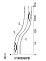
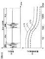
- FIG. 17 shows the current (line L50, line L51), temperature (line L52), and effective current (or average current) in the time window Tw1 (line L53, line) of the assembled battery 110 during charging and discharging in the first embodiment. It is a figure which shows transition of L54).
- FIG. 18 is a block diagram showing an assembled battery control unit 150A in the second embodiment.
- FIG. 19 is a block diagram showing the power amount limiting coefficient determination unit 154.
- FIG. 20 is a diagram illustrating an example of the definition of electric energy.
- FIG. 21 is a block diagram showing the power amount limiting unit 155. As shown in FIG. FIG. FIG.
- FIG. 22 is a diagram illustrating changes in temperature (line L61), state of charge (SOC) (line L62), and electric energy (line L63) during charging / discharging of the assembled battery 110 according to the second embodiment.
- FIG. 23 is a diagram for explaining the definition of the duty ratio and the current limiting characteristic according to the duty ratio.
- FIG. 24 is a block diagram showing the current limit value determining unit 151B.
- PHEV plug-in hybrid vehicle
- a storage battery control circuit of a power storage device that constitutes a power supply for an industrial vehicle such as a passenger vehicle such as a hybrid vehicle (HEV) or an electric vehicle (EV) or a hybrid railway vehicle.
- HEV hybrid vehicle
- EV electric vehicle
- a lithium ion battery is applied to a capacitor constituting the power storage unit.
- the capacitor a nickel metal hydride battery, a lead battery, an electric double layer capacitor, a hybrid capacitor, etc. are used. You can also
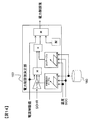
- FIG. 1 is a diagram for explaining a battery system mounted on a plug-in hybrid vehicle.
- the battery system 10 including the assembled battery 110 is connected to the inverter 400 via the switches 300 and 310 and is connected to the charger 420 via the switches 320 and 330.
- Inverter 400 and charger 420 are controlled by vehicle control unit 200.
- the battery system 10 is connected to the inverter 400, and the motor generator 410 is driven by the energy stored in the assembled battery 110.
- the motor generator 410 functions as a generator, and the three-phase AC power output from the motor generator 410 is converted into DC power by the inverter 400 to charge the assembled battery 110 provided in the battery system 10. Used.
- the battery system 10 is connected to the charger 420, and the assembled battery 110 is charged by supplying power from a household power supply or a desk lamp.
- the battery system 10 includes an assembled battery 110 and a battery control system 100 that monitors and controls the state of the assembled battery 110.
- the battery control system 100 includes a single battery management unit 120, a current detection unit 130, a voltage detection unit 140, an assembled battery control unit 150, and a storage unit 180.
- the assembled battery 110 includes a plurality of single cells 111.
- the unit cell management unit 120 monitors the state of the unit cells 111 constituting the assembled battery 110.
- the current detection unit 130 detects a current flowing through the battery system 10.
- the voltage detection unit 140 detects the total voltage of the assembled battery 110.
- the assembled battery control unit 150 controls the assembled battery 110.
- the storage unit 180 stores information regarding battery characteristics of the assembled battery 110, the single battery 111, and the single battery group 112.
- the assembled battery 110 is configured by electrically connecting a plurality of unit cells 111 (lithium ion batteries) capable of storing and releasing electrical energy (charging and discharging DC power) in series.
- the output voltage of the unit cell 111 is, for example, 3.0 to 4.2 V (average output voltage: 3.6 V). Of course, other voltage specifications may be used.
- the assembled battery 110 is composed of a plurality of unit cells 111 electrically connected in series.
- the plurality of single cells 111 constituting the assembled battery 110 are grouped into a plurality of single cell groups 112 including a predetermined number of single cells 111 for convenience of managing and controlling the battery state.
- the unit cell group 112 may be equally divided by a predetermined unit number such as 1, 4, 6,..., Or the unit cell groups 112 and 6 each including four unit cells 111. There is a case where the composite section is combined with a unit cell group 112 composed of individual unit cells 111.
- the assembled battery 110 includes two unit cell groups 112a and 112b formed by electrically connecting four unit cells 111 in series. It is configured to be connected in series and includes a total of eight unit cells 111.
- the unit cell management unit 120 includes a plurality of unit cell control units 121, and one unit cell control unit 121 is assigned to the unit cell group 112 grouped as described above.
- the unit cell control unit 121 operates by receiving power from the allocated unit cell group 112, and monitors and controls the state of the unit cells 111 constituting the unit cell group 112.
- the single cell management unit 120 is provided with two single cell control units 121a and 121b corresponding to the two single cell groups 112a and 112b.
- the assembled battery control unit 150 is transmitted from the voltage detection unit 140, the battery voltage and temperature of the single cell 111 transmitted from the single cell management unit 120, the current value flowing through the battery system 10 transmitted from the current detection unit 130, and the voltage detection unit 140.
- the total voltage value of the assembled battery 110 is input.
- the assembled battery control unit 150 detects the state of the assembled battery 110 based on the input information.
- the result of the process performed by the assembled battery control unit 150 is transmitted to the single cell management unit 120 and the vehicle control unit 200.
- Signal transmission / reception between the assembled battery control unit 150 and the unit cell management unit 120 is performed by a signal communication unit 160 provided with an insulating element 170 such as a photocoupler.
- the insulating element 170 is provided because the operating voltage of the assembled battery control unit 150 and the operating power source of the unit cell management unit 120 are different.
- the cell management unit 120 operates by receiving power from the assembled battery 110, whereas the assembled battery control unit 150 uses a battery for on-vehicle auxiliary equipment (for example, a 14V battery) as a power source.
- the insulating element 170 may be mounted on a circuit board constituting the unit cell management unit 120 or may be mounted on a circuit board constituting the assembled battery control unit 150. Depending on the system configuration, the insulating element 170 may be omitted.
- the cell control units 121a and 121b described above are connected in series by the signal communication unit 160 in the descending order of potential of the cell groups 112a and 112b monitored by each.
- the signal transmitted by the assembled battery control unit 150 is input to the single cell control unit 121a by the signal communication unit 160 via the insulating element 170.
- the signal communication unit 160 connects between the output of the unit cell control unit 121a and the input of the unit cell control unit 121b, and signals are transmitted.
- the output of the cell control unit 121b is transmitted to the battery pack control unit 150 by the signal communication unit 160 via the insulating element 170.
- the assembled battery control unit 150 and the single cell control units 121a and 121b are connected in a loop by the signal communication unit 160.
- This loop connection may be referred to as a daisy chain connection, a daisy chain connection, or a random connection.
- the unit cell control unit 121a and the unit cell control unit 121b are connected not via the insulating element 170, but may be connected via the insulating element 170.
- the storage unit 180 stores information on current limiting characteristics of the battery system 10 and battery characteristics of the assembled battery 110, the single battery 111, and the single battery group 112.
- the battery characteristics include, for example, data tables and formulas describing the relationship between the state of charge (SOC: State of charge) and open circuit voltage (OCV: Open Circuit Voltage), internal resistance characteristics, polarization resistance characteristics, etc.
- SOC State of charge
- OCV Open Circuit Voltage
- the storage unit 180 is installed outside the assembled battery control unit 150 and the unit cell management unit 120, but the assembled battery control unit 150 or the unit cell management unit 120 stores the storage unit. The above information may be stored in this configuration.
- FIG. 2 is a diagram illustrating a circuit configuration of the unit cell control unit 121.
- the unit cell control unit 121 includes a voltage detection circuit 122, a control circuit 123, a signal input / output circuit 124, and a temperature detection unit 125.
- the voltage detection circuit 122 measures the voltage between the terminals of each unit cell 111.
- the temperature detection unit 125 measures the temperature of the cell group 112.
- the control circuit 123 transmits the measurement results input from the voltage detection circuit 122 and the temperature detection unit 125 to the assembled battery control unit 150 via the signal input / output circuit 124.
- the single cell control unit 121 is generally provided with a circuit for equalizing voltage variations between the single cells 111 caused by self-discharge and current consumption variations. Is done.
- the temperature detection unit 125 provided in the unit cell control unit 121 measures one temperature as the entire unit cell group 112 and treats that temperature as a representative temperature value of the unit cells 111 constituting the unit cell group 112.
- the temperature measured by the temperature detection unit 125 is used for various calculations for detecting the state of the cell 111, the cell group 112, or the assembled battery 110.
- a temperature detector 125 may be provided for each unit cell 111 to measure the temperature for each unit cell 111 and perform various calculations based on the temperature for each unit cell 111.
- the configuration of the unit cell control unit 121 becomes complicated as the number of the temperature detection units 125 increases.
- FIG. 2 shows the temperature detection unit 125 in a simplified manner, but actually, a temperature sensor is installed on the temperature measurement target, and a voltage as temperature information is output from the temperature sensor.
- This measurement result is transmitted to the signal input / output circuit 124 via the control circuit 123, and is output to the outside of the unit cell control unit 121 by the signal input / output circuit 124.
- the unit cell control unit 121 is equipped with a function for realizing this series of flows as a temperature detection unit 125.
- the voltage detection circuit 122 can also be used to measure temperature information (voltage).
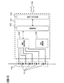
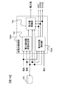
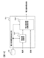
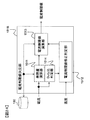
- FIG. 3 is a block diagram illustrating a configuration of the assembled battery control unit 150.
- the assembled battery control unit 150 includes a current limit value determination unit 151, a battery state detection unit 152, and a power limit calculation unit 153.
- the assembled battery control unit 150 includes the measured values of the battery voltage and temperature of the unit cell 111 output from the unit cell management unit 120, the current value from the current detection unit 130, and the assembled battery 110 output from the voltage detection unit 140.
- the total voltage value, the battery characteristic information of the cell 111 stored in the storage unit 180, and a current limit value described later are input.
- the cell management unit 120 has a function of diagnosing whether the cell 111 is overcharged or overdischarged, and a function of outputting an abnormal signal when a communication error occurs in the cell management unit 120. These diagnosis results and abnormal signals are also input to the battery pack controller 150.
- a signal is also input from the vehicle control unit 200 which is a host control device.
- the assembled battery control unit 150 is configured to appropriately control charging / discharging of the assembled battery 110 based on the input information and the current limit value stored in advance in the storage unit 180 and the battery characteristics of the unit cell 111. Calculation of the limit value, calculation of the power limit value, calculation of the SOC and deterioration state (SOH: State Of Health) of the cell 111, and calculation for performing voltage equalization control are executed. The assembled battery control unit 150 outputs these calculation results and instructions based on the calculation results to the unit cell management unit 120 and the vehicle control unit 200.
- the current limit value determination unit 151 illustrated in FIG. 3 will be described in more detail with reference to FIG.
- FIG. 4 is a block diagram illustrating a configuration of the current limit value determination unit 151.
- the current limit value determination unit 151 includes a heat generation amount calculation unit 1511, a current limit value correction determination unit 1512, and a current limit value calculation unit 1513.
- the heat generation amount calculation unit 1511 calculates the heat generation amount of the assembled battery 110 or the single battery 111 based on the current detected by the current detection unit 130.
- the current limit value correction determination unit 1512 determines whether or not the current limit value needs to be corrected based on the heat generation amount calculated by the heat generation amount calculation unit 1511 and the battery temperature detected by the temperature detection unit 125.
- the current limit value calculation unit 1513 receives the output from the heat generation amount calculation unit 1511 (heat generation amount) and the output from the current limit value correction determination unit 1512 (determination of whether or not the current limit value needs to be corrected).
- the current limit value calculation unit 1513 corrects the current limit value stored in advance in the storage unit 180 based on the input information, and outputs the corrected current limit value.
- the corrected current limit value is stored in the storage unit 180 separately from the current limit value stored in advance.
- FIG. 5 shows an example of the current limiting characteristic stored in the storage unit 180.
- the current limiting characteristic shown in FIG. 5 shows the current limiting value for each time window.
- the current limit value is a limit value for controlling the current value to a value for suppressing a decrease in output due to deterioration without departing from the thermal restriction of the battery system 10.
- the average value or effective value of the current that does not deviate from the thermal constraints of the battery system 10 or promote the progress of deterioration is extracted from an experiment or the like in which an arbitrary current waveform is input to the battery system 10 in advance.
- These are the current limit values.
- the thermal influence on the battery system 10 and the influence on the deterioration characteristics vary depending on the time during which the current flows. Therefore, in the present embodiment, the current limit value is set according to the time window as shown in FIG.
- FIG. 6 is a diagram for explaining the time windows Tw1 to Twn.
- time windows Tw1 to Tw4 are shown so as to overlap the time change of the current value indicated by the line L1.
- the time windows Tw4 to Twn are not shown.
- the time window defines the time width when data sampling is performed.
- time widths (time windows) Tw1 to Tw4 that are traced back to the past from the current time are represented as time T1 and time T2. It is shown.
- the time windows Tw1 to Tw4 move to the right in the figure, and the sampling data in the time windows Tw1 to Tw4 also change.
- the storage unit 180 stores the current limiting characteristics shown in FIG. 5 as a data table as shown in FIG. Further, instead of the data table, the correspondence between the time window and the current limit value may be expressed by a mathematical expression or the like, and is not limited to the form of the data table. Note that the current limit value may be determined in consideration of not only the thermal restrictions of the assembled battery 110 or the single battery 111 but also the deterioration characteristics of the assembled battery 110 or the single battery 111, the thermal restrictions of the members of the switch 300, and the like. good.
- FIG. 8 is a block diagram showing the processing contents of the calorific value calculation unit 1511. Based on the current value I (A) detected by the current detection unit 130 and the internal resistance R ( ⁇ ) of the cell 111 stored in the storage unit 180, the heat generation amount calculation unit 1511 According to 1), calorific values Q Tw1 to Q Twn (J) corresponding to the time windows Tw1 to Twn (sec) are calculated.
- the calorific values Q Tw1 to Q Twn calculated by the calorific value calculation unit 1511 are measured data of the current value Ii acquired for each time window Tw1 to Twn as shown in FIG. 6 (i is data acquired for each sampling period). The sample number is indicated). Each calculation result is output from the calorific value calculation unit 1511.
- the value of the internal resistance is a constant value, but the value of the internal resistance may be changed according to the SOC and temperature to calculate the heat generation amount.
- Figure 9 is a diagram illustrating a calorific value Q Tw1 ⁇ Q Twn per time window Tw1 ⁇ Twn, it illustrates in time windows Tw1 ⁇ Tw4.
- a line L2 indicates a change over time in the accumulated value of the heat generation amount.
- the heat generation amounts Q Tw1 to Q Tw4 correspond to the heat generation amounts generated in the time windows Tw1 to Tw4.
- the heat generation amount is calculated from the equation (1).
- a parameter that can serve as an index for preventing a reduction in output due to thermal restriction or deterioration is not limited to the amount of heat generated by the formula (1), and for example, the current square of the current flowing through the assembled battery 110 or the single battery 111.
- the integrated value may be calculated and output from the following formula (2) according to the time window, or the average value of the current flowing through the assembled battery 110 or the single battery 111 may be calculated from the following formula (3) according to the time window. You may calculate and output. Furthermore, it is good also as a structure which calculates and outputs the temperature change for every certain time window.
- FIG. 10 is a block diagram showing the current limit value correction determination unit 1512.
- the current limit value correction determination unit 1512 includes a correction determination unit 15121 and a correction necessity determination unit 15122.
- the correction determination unit 15121 is provided for each of the time windows Tw1 to Twn.
- the correction determination unit 15121 determines the amount of heat generated in the time window and the temperature change in the time window. The comparison is made every Tw1 to Twn, and the comparison result is output. First, the correction determination unit 15121 uses the heat generation amounts Q Tw1 to Q Twn for each of the time windows Tw1 to Twn calculated by the heat generation amount calculation unit 1511 as the heat generation amount threshold value Q th1 preset for each of the time windows Tw1 to Twn. Compare with ⁇ Q thn . The modification judging unit 15121 is, whether the calorific value Q Tw1 ⁇ Q Twn reaches the threshold value Q th1 ⁇ Q thn, determines for each time window Tw1 ⁇ Twn.
- the temperature ⁇ T changes in the time acquired by the temperature detection unit 125 and the temperature change threshold values (lower threshold value ⁇ T LT , upper threshold value ⁇ T UT ). Compare the magnitude relationship with.
- the temperature change threshold is set for each of the time windows Tw1 to Twn. That is, as the width of the time window is larger, the temperature change thresholds (lower threshold ⁇ T LT , upper threshold ⁇ T UT ) are also set to larger values. This determination and comparison is performed for each time window, and the comparison result is output from the correction determination unit 15121.
- FIG. 11 is a diagram showing a temperature change for each time window. In FIG.
- a line L3 indicates a time-series change in temperature.
- Temperatures Tcell1 to Tcell4 indicate the time at the left end position (start position) of the time windows Tw1 to Tw4. Then, the temperature change ⁇ T Tw1 ⁇ T Tw4 in each time window Tw1 ⁇ Tw4 can be expressed by the difference between the temperature Tcell and the temperature Tcell1 ⁇ Tcell4 at the current time.
- the flag “1” is output, and when the temperature change ⁇ T is lower than a certain threshold ( ⁇ T ⁇ ⁇ T LT ).
- the flag “2” is output to the flag “0”, and when the temperature change ⁇ T is within the threshold value ( ⁇ T LT ⁇ ⁇ T ⁇ ⁇ T UT ), the flag “0” is output.
- a determination result for each of the time windows Tw1 to Twn is input from the correction determination unit 15121 to the correction necessity determination unit 15122.
- the correction necessity determination unit 15122 determines whether or not the current limit value should be corrected based on the determination results for each of the time windows Tw1 to Twn, and outputs the correction necessity determination result. For example, there is a method of outputting the flag having the largest number among the plurality of flags input from the correction determination unit 15121 as the correction necessity determination result output.
- the flag input for each time window from the correction determination unit 15121 may be output for each time window as it is so that a current limit value correction process described later can be executed for each time window.
- the correction determination result of the correction determination unit 15122 may be counted for a predetermined number of times, and whether or not correction is necessary is determined based on the counted result and output.
- FIG. 12 is a block diagram showing the current limit value calculation unit 1513.
- the current limit value calculation unit 1513 includes a current limit value correction unit 15131, a current limit determination unit 15132, and a current limit value setting unit 15133.
- the current limit determination unit 15132 is provided for each of the time windows Tw1 to Twn.
- the current limit value correction unit 15131 executes a current limit value correction process based on the correction necessity determination flag input from the current limit value correction determination unit 1512 illustrated in FIG.
- the correction result is stored in the storage unit 180 and output to the current limit determination unit 15132.
- FIG. 13 is a diagram illustrating a current limit value correction process.
- a line L40 is a current limiting characteristic set at the present time.
- the current limiting characteristic stored in advance in the storage unit 180 is set as the current limiting characteristic. If the input correction necessity determination flag is a flag requesting correction, the setting of the current limiting characteristic is changed from the line L40 to the lines L41 and L42.
- correction necessity determination unit 15122 is configured to output the flag having the largest number among the plurality of flags input from the correction determination unit 15121. If modification request judgment flag is "1", among the plurality of time windows heating value exceeds the threshold value, that the number of time windows the temperature change [Delta] T is higher than the upper limit threshold [Delta] T UT is most often become. In this case, it is determined that the current limit is insufficient (insufficient), and the current limit characteristic is corrected so as to increase the current limit. That is, the current limiting characteristic indicated by the line L40 in FIG. 13 is corrected downward as indicated by the line L41, and the current limiting value of all time windows is corrected to be small. As a result, the current limit is further strengthened.
- the correction request determination flag is “2”
- the current limit characteristic is corrected so as to loosen the limit. That is, the current limiting characteristic indicated by the line L40 in FIG. 13 is corrected upward as indicated by the line L42 so that the current limiting values of all the time windows are increased. If the correction request determination flag is “0”, it is determined that the current limit is appropriate, and the current limit characteristic is not corrected.
- the correction necessity determination unit 15122 in FIG. 10 is configured to output the flag input from the correction determination unit 15121 for each time window as it is for each time window, the current is output for each time window.
- the limit value may be corrected. That is, instead of correcting the current limit characteristic L40 upward or downward as a whole, the current limit value is corrected every time window. Further, the correction amount of the current limit value may be such that, for example, when the correction determination request flag is “1” or “2”, the 1 A current limit value may be corrected downward or corrected upward.
- a correction amount corresponding to the difference between the actual temperature rise and the temperature rise threshold may be determined in advance.
- the current limit determination unit 15132 receives the corrected current limit value from the current limit value correction unit 15131 and the heat generation amounts Q Tw1 to Q Twn for the time windows Tw1 to Twn calculated by the heat generation amount calculation unit 1511.
- the Current restriction determination unit 15132 determines whether the calculation result of the calorific value Q Tw1 ⁇ Q Twn in accordance with the time window has reached the threshold Q th1 ⁇ Q thn calorific value, sets a limit request flag. For example, the restriction request flag is set to “1” when the heat generation amount reaches the threshold value, and the restriction request flag is set to “0” when it has not reached. After setting the limit request flag, it outputs it to the current limit value setting unit 15133.
- the current limit value setting unit 15133 sets the current limit value based on the limit request flag input from the limit determination unit 15132. As a method of setting the current limit value, for example, among a plurality of set time windows, the current limit value having the smallest value among the current limit values in the time window in which the calorific value is determined to be higher than the threshold value is determined. Set to.
- the current limit value used here is the current limit value after the change when the temperature change ⁇ T in the time window is out of the threshold range and changed from the line L40 to the lines L41 and L42. .
- the battery state detection part 152 which comprises the assembled battery control part 150 is demonstrated.
- the battery state detection unit 152 is based on the voltage of the single cell 111 measured by the single cell control unit 120, the current value acquired by the current detection unit 130, and the battery temperature acquired by the temperature detection unit 125. Is calculated.
- the SOC is expressed as a ratio between the capacity Qmax at the time of full charge and the capacity Qremain currently stored in the battery.
- the deterioration state SOHR based on the internal resistance is expressed as a ratio between the internal resistance R0 at the time of a new product and the current internal resistance R1, as shown by the following formula (5).
- the calculation method of SOC and SOHR is omitted as it is known.
- FIG. 14 is a block diagram showing the power limit calculation unit 153.
- the power limit calculation unit 153 receives the current limit value determined by the current limit value determination unit 151, the SOC and SOHR calculated by the battery state detection unit 152, and the battery temperature detected by the temperature detection unit 125. .
- the power limit calculation unit 153 calculates and outputs the power limit value of the assembled battery 110 based on these input values.
- the power limit value is calculated by the following formula (6) based on the current limit value and the voltage of the assembled battery 110 when a current corresponding to the current limit value is energized to the assembled battery 110.
- N is the number (units) of unit cells 111 constituting the assembled battery 110
- I limit is the current limit value (A)
- OCV is the open circuit voltage (V)
- R0 is the internal resistance ( ⁇ ) and SOHR indicate the deterioration state (%).
- step S100 it is determined whether or not a vehicle activation signal (a signal indicating whether or not the vehicle has been activated) has been received. If it determines with having received the vehicle starting signal, it will progress to step S110 from step S100.
- a vehicle activation signal a signal indicating whether or not the vehicle has been activated
- step S110 calorific values Q Tw1 to Q Twn are calculated for each of the time windows Tw1 to Twn, and the battery temperature is measured.
- step S120 the time window Tw1 ⁇ calorific value Q Tw1 ⁇ Q Twn computed for each Twn determines whether the threshold Q th1 ⁇ Q thn least every time window Tw1 ⁇ Twn.
- the process returns to step S110.
- the process proceeds to step S130.
- step S130 the temperature changes ⁇ T Tw1 to T Tw4 acquired for each of the time windows Tw1 to Twn are compared with the temperature change threshold values (lower limit value ⁇ T LT , upper limit value ⁇ T UT ), and the temperature change ⁇ T is compared with the upper limit value ⁇ T UT . It is determined whether it is above or below the lower limit value ⁇ T LT . That is, it is determined whether or not the temperature change ⁇ T is outside the threshold range. If it is determined as YES (out of range) in step S130, the process proceeds to step S140. If it is determined NO (in range), the process proceeds to step S150.
- step S140 current limit value correction processing is executed. Details of the correction process will be described later.
- step S150 a current limit value is determined. That is, when it is determined in step S130 that the temperature change ⁇ T is outside the threshold range, the current limit value is corrected, and the current limit value is determined using the corrected current limit value. On the other hand, when it is determined in step S130 that the temperature change ⁇ T is within the threshold range, the current limit value is determined using the current current limit value before correction.
- step S160 the power limit value is determined based on the current limit value.
- FIG. 16 is a flowchart illustrating an example of the current limit value correction process in step S140.
- step S141 it determines whether the temperature change [Delta] T in the time window exceeds the upper limit value [Delta] T UT.
- step S142 the process proceeds to step S143 otherwise.
- step S142 it is determined that the temperature change ⁇ T is high, that is, the assembled battery 110 or the single battery 111 is in a state of excessive heat generation, and the current limit value is decreased (that is, the limit is increased). Correct it.
- step S143 it is determined that the temperature change is low, that is, the assembled battery 110 or the single battery 111 is not generating heat, and the current limit value is increased (that is, the limit is relaxed).
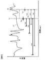
- FIG. 17A shows an example of a current waveform flowing through the assembled battery 110
- FIG. 17B shows an example of a temperature waveform of the assembled battery 110
- FIG. 17C shows an effective current in the time window Tw1. (Or the average current) is shown, and a state in which charging / discharging is controlled based on two time windows Tw1 and Tw2 is shown.
- Tw1 the time window
- Tw2 the time window
- the current limit correction process in the section of the time window Tw1 is shown. That describes only effect of limiting values of a time window Tw1 is modified from I th1 of FIG. 17 (c) on to the I th1 '.
- the battery temperature increase ⁇ T Tw2 is detected.
- the temperature rise ( ⁇ T Tw2 ) measured from the temperature waveform (line L52) is smaller than the lower limit threshold for temperature rise ( ⁇ T Tw2 ⁇ ⁇ T LT ) as shown in FIG.
- the current limit value stored in 180 excessively limits the current, and the limit of the current limit value corresponding to each time window in which the current limit value is stored in advance in the storage unit 180 is relaxed. Correct in the direction. That is, herein, to modify the I th1 as shown in FIG. 17 (c) to I th1 '.
- the effective current value (or the average current value) after the current limit value correction shown in the line L53 in FIG. 17C is compared with the case of no correction shown in the line L54 in FIG. , Big value.
- the current value after correction of the line L50 in FIG. 17A also has a larger absolute value of current than the current value without correction shown in the line L51.
- FIG. 17 illustrates an example in which charge / discharge is controlled based on the corrected current limit value, but charge / discharge is controlled based on the power limit value determined based on the corrected current limit value. Also good.
- the degree of temperature increase differs depending on the difference between the battery temperature and the ambient temperature of the battery.
- the temperature rises, but eventually, the point where the heat generation and heat dissipation of the battery are balanced (the heat dissipation amount that increases according to the difference between the battery temperature and the ambient temperature is equal to the heat generation amount of the battery) Point).
- the heat generation and heat dissipation of the battery are balanced, the temperature change in the time window becomes small despite charging and discharging, so it is determined that the temperature rise in the time window is below the threshold, and the current limit is excessively relaxed. There is a possibility that. For this reason, the difference between the ambient temperature of the battery and the current temperature may be obtained, and the temperature increase threshold value ( ⁇ T UT or ⁇ T LT ) for each time window may be determined accordingly.
- the present embodiment it is possible to appropriately set the current limit value or the power limit value based on the temperature rise of the battery, so that the output reduction due to deterioration does not deviate from the thermal restriction of the battery. Suppressible charge / discharge control can be realized.
- the battery system does not deviate from thermal restrictions and suppresses output reduction due to deterioration of the secondary battery. Charge / discharge control can be realized.
- the amount of power (unit: Wh) of the assembled battery 110 is limited to solve the above problem. I tried to do it.
- the configuration example of the power storage device of the plug-in hybrid vehicle in the present embodiment is the same as in FIG. Moreover, although the structural example of the cell control part 121 in this embodiment is the same as that of FIG. 2, only the structure of the assembled battery control part 150 is different. Below, the assembled battery control part from which a structure differs is demonstrated.
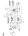
- FIG. 18 is a block diagram showing the assembled battery control unit 150A in the present embodiment.
- the assembled battery control unit 150A corresponds to the assembled battery control unit 150 shown in FIG.
- the assembled battery control unit 150A includes a battery state detection unit 152A, a power amount restriction coefficient determination unit 154, and a power amount restriction unit 155.
- the power amount limiting coefficient determination unit 154 determines a limiting coefficient for limiting the power amount based on the current input from the current detection unit 130 and the battery temperature input from the temperature detection unit 125.
- the power amount restriction unit 155 calculates the power amount based on the restriction coefficient determined by the power amount restriction coefficient determination unit 154 and the battery temperature from the temperature detection unit 125.
- the battery state detection unit 152A corresponds to the battery state detection unit 152 of the first embodiment, and calculates the deterioration state SOHQ of the unit cell 111 in addition to the SOC and SOHR of the unit cell 111.
- This SOHQ indicates the rate of decrease of the full charge capacity of the unit cell 111 due to deterioration, and is defined by the following formula (7) using the full charge capacity Qmax0 when new and the full charge capacity Qmax after deterioration. Is done.
- the calculation method of SOHQ is a well-known thing, the detail is abbreviate
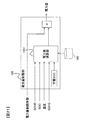
- FIG. 19 is a block diagram showing the power amount limiting coefficient determination unit 154.
- the power amount limiting coefficient determining unit 154 includes a heat generation amount calculating unit 1541 and a power amount limiting coefficient calculating unit 1542.
- the calorific value calculation unit 1541 is the same as the calorific value calculation unit 1511 of the first embodiment, and has the same configuration as that shown in FIG. .
- the power amount limit coefficient calculation unit 1542 determines and outputs a power amount limit coefficient based on the heat generation amount Q calculated by the heat generation amount calculation unit 1541 and the battery temperature measured by the temperature detection unit 125.
- the power amount limiting coefficient calculation unit 1542 provides a heat generation amount threshold value (Q th1 to Q thn ) for each time window, and when the heat generation amount reaches the threshold value, the temperature change threshold value ( ⁇ T LT , ⁇ T UT ) and the obtained temperature change Compare with ⁇ T Tw . Then, in any time window, when the temperature change ⁇ T Tw is ⁇ T Tw ⁇ ⁇ T UT , for example, a value smaller than 1 is output as the power amount limiting coefficient.
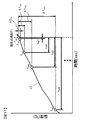
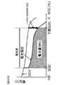
- FIG. 20 is a diagram illustrating an example of the definition of the electric energy, where the horizontal axis indicates the SOC and the vertical axis indicates the battery voltage.
- the waveform indicated by the dotted line indicates the open circuit voltage (OCV) of the unit cell 111
- the waveform indicated by the solid line indicates the battery voltage when energized with a certain current.
- the battery voltage in the equation (8) is calculated by the following equation (9) using the open circuit voltage (OCV), the internal resistance (R), and the rate of increase of the internal resistance (degraded state SOHR).
- the current value used for the electric energy calculation included in Equation (9) may be a fixed value, or may be variable based on past current history.
- the amount of electricity in the equation (8) is calculated from the current SOC to the lower limit SOC using the current SOC (SOC), the lower limit SOC, the full charge amount Qmax0 at the time of a new product, and the rate of decrease of the full charge capacity (SOHQ). Is calculated from the following equation (10).
- the lower limit SOC in the equation (10) may be defined as a function of temperature and deterioration state as an SOC for securing a minimum output necessary for the vehicle to travel, or may be a fixed value, for example, actual use It may be defined as the lower limit SOC of the battery at the time.
- FIG. 21 is a block diagram showing the power amount limiting unit 155.
- the power amount calculation unit 1551 provided in the power amount restriction unit 155 calculates the power amount based on Expression (8).
- the calculation result is multiplied by the limit coefficient input from the power amount limit coefficient determination unit 154 and output as the final power amount.
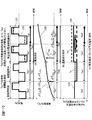
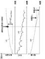
- FIG. 22 shows three graphs. From the top, a graph plotting changes in temperature (line L61), SOC (line L62), and electric energy (line L63) during charging / discharging of the assembled battery 110 is shown. Show.
- the temperature change detected by the temperature detection unit 125 is greater than a preset temperature change threshold value.
- the power amount limiting coefficient determination unit 154 determines a limiting coefficient and limits the power amount.
- the configuration of the assembled battery control unit 150A described above is merely an example, and is not limited to the configuration described above (for example, the configuration in FIG. 21).
- the current is limited in accordance with a ratio of energization time within a certain period (hereinafter, this ratio is referred to as a Duty ratio).
- FIG. 24 is a block diagram showing the current limit value determining unit 151B.
- FIG. 23A is a diagram for explaining the definition of the duty ratio
- FIG. 23B is a diagram showing the current limiting characteristic according to the duty ratio.
- a current limit value corresponding to the duty ratio is determined. Then, at the time of designing the battery system, a current limit value corresponding to the duty ratio corresponding to the usage frequency of the user is set in advance.
- a line L71 indicates a current limit value set in advance for each time window as described above, and is stored in the storage unit 180.
- a current limit value determination unit 151B is obtained by further adding a duty ratio determination unit 1514 to the current limit value determination unit 151 in the first embodiment.
- the battery control system 100 can perform the same current limit control as in the first embodiment, and further according to the usage state of the assembled battery 110 (according to the duty ratio). It is possible to calculate an appropriate current limit value or power limit value. As a result, a battery control system capable of achieving both protection of the battery system and maximum utilization of energy can be provided.
- the restriction process according to the duty ratio in the present embodiment can also be applied to the cases of the first and second embodiments described above.
- the battery control system 100 includes the current detection unit 130 that detects the current of the unit cell 111, the temperature detection unit 125 that detects the temperature of the unit cell 111, and the unit in the predetermined time windows Tw1 to Twn. Based on the current and temperature history of the battery 111 (for example, calorific values Q Tw1 to Q Twn , temperature changes ⁇ T Tw1 to T Tw4 ), the current of the cell 111 is limited so that the current value does not exceed the current limit value. And a control unit 150 that performs restriction control.
- the control unit 150 when a predetermined time window Tw1 change in temperature [Delta] T Tw1 in ⁇ Twn ⁇ T Tw4 is within a predetermined range (less than or equal to the upper limit threshold value [Delta] T UT at the lower limit threshold [Delta] T LT or higher) has already been set.
- the first current limit value line L40 in FIG. 13
- the temperature changes ⁇ T Tw1 to T Tw4 in the predetermined time windows Tw1 to Twn are outside the predetermined range
- the first current limit values are different.
- the setting is changed to the second current limit value (lines L41 and L42 in FIG. 13), and the current is limited by the second current limit value after the setting change.
- the preset current limit value is set on the premise of a predetermined load pattern, when the current limit is performed using only the current limit value as in the conventional case, for example, the battery is used in a high load pattern. In some cases, the battery temperature may rise excessively and deviate from the thermal constraints of the battery. Conversely, when used in a low load pattern, there is a possibility of excessive current limiting. However, in the present embodiment, as described above, the current limit value is changed according to the temperature change of the battery, so that the current limit according to the actual use state can be performed, which is too small or too large. Current limit can be avoided, and the current limit value can be appropriately set according to the state of the battery system.
- the second current limit value is set to a value smaller than the first current limit value when the temperature change exceeds a predetermined range, and is larger than the first current limit value when the temperature change falls below the predetermined range. It is good to be said.
- the predetermined time window is composed of a plurality of time windows Tw1 to Twn having different time widths, and a change in temperature for each of the plurality of time windows Tw1 to Twn is compared with a predetermined range set for each of the time windows Tw1 to Twn.
- the battery control system 100 also includes a current detection unit 130 that detects the current of the unit cell 111, a temperature detection unit 125 that detects the temperature of the unit cell 111, and the current and temperature of the unit cell 111 in a predetermined time window Tw1 to Twn. And a control unit 150 that performs restriction control for restricting a change in the electric energy of the single battery 111 based on the history of As described above, when the amount of power is limited by detecting an excessive temperature rise, the calculation result is smaller than when the amount of power is not limited (line indicated by a broken line) as shown by a line L63 in FIG. Thus, the transient use of the unit cell 111 can be avoided.
- the battery heat parameter As the current history, the battery heat parameter, the amount of heat generated by the battery based on the internal resistance of the battery and the current detected by the current detector, and the current square integrated value based on the current detected by the current detector Alternatively, an average current section value in a time window may be used.
- a duty ratio detection unit 1514 is provided as a duty ratio detection unit that detects a duty ratio as a ratio of current application time in a certain period, and the first and second current limit values are based on the duty ratio by the duty ratio determination unit 1514. That is, the lines L41 and L42 shown in FIG. 13 are further changed to lines L72 and L73 in FIG. 23B based on the duty ratio. As a result, it is possible to calculate an appropriate current limit value or power limit value according to the usage state of the battery (according to the duty ratio), and it is possible to achieve both protection of the battery system and maximum utilization of energy. Become.
Landscapes
- Engineering & Computer Science (AREA)
- Power Engineering (AREA)
- Mechanical Engineering (AREA)
- Sustainable Energy (AREA)
- Sustainable Development (AREA)
- Transportation (AREA)
- Life Sciences & Earth Sciences (AREA)
- Manufacturing & Machinery (AREA)
- Chemical & Material Sciences (AREA)
- Chemical Kinetics & Catalysis (AREA)
- Electrochemistry (AREA)
- General Chemical & Material Sciences (AREA)
- Charge And Discharge Circuits For Batteries Or The Like (AREA)
- Tests Of Electric Status Of Batteries (AREA)
- Secondary Cells (AREA)
Applications Claiming Priority (2)
| Application Number | Priority Date | Filing Date | Title |
|---|---|---|---|
| JP2013-205254 | 2013-09-30 | ||
| JP2013205254A JP6174963B2 (ja) | 2013-09-30 | 2013-09-30 | 電池制御システム |
Publications (1)
| Publication Number | Publication Date |
|---|---|
| WO2015045505A1 true WO2015045505A1 (ja) | 2015-04-02 |
Family
ID=52742663
Family Applications (1)
| Application Number | Title | Priority Date | Filing Date |
|---|---|---|---|
| PCT/JP2014/065835 Ceased WO2015045505A1 (ja) | 2013-09-30 | 2014-06-16 | 電池制御システム |
Country Status (2)
| Country | Link |
|---|---|
| JP (1) | JP6174963B2 (enExample) |
| WO (1) | WO2015045505A1 (enExample) |
Cited By (3)
| Publication number | Priority date | Publication date | Assignee | Title |
|---|---|---|---|---|
| CN107179510A (zh) * | 2016-03-10 | 2017-09-19 | 福特全球技术公司 | 电池端电压预测 |
| CN108028438A (zh) * | 2015-09-09 | 2018-05-11 | 日立汽车系统株式会社 | 蓄电池控制装置 |
| JP2019175594A (ja) * | 2018-03-27 | 2019-10-10 | 日立オートモティブシステムズ株式会社 | 電池管理装置、電池管理方法、電力貯蔵システム |
Families Citing this family (9)
| Publication number | Priority date | Publication date | Assignee | Title |
|---|---|---|---|---|
| US10170804B2 (en) | 2015-06-15 | 2019-01-01 | Gs Yuasa International Ltd. | Monitoring device for secondary battery, battery pack, and vehicle |
| JP6787660B2 (ja) | 2015-12-10 | 2020-11-18 | ビークルエナジージャパン株式会社 | 電池制御装置、動力システム |
| JP2018093624A (ja) * | 2016-12-02 | 2018-06-14 | 株式会社オートネットワーク技術研究所 | 給電制御装置、給電制御方法及びコンピュータプログラム |
| JP6858060B2 (ja) * | 2017-04-10 | 2021-04-14 | 株式会社日立製作所 | 鉄道車両用駆動システムおよび鉄道車両用蓄電装置の制御方法 |
| KR102710752B1 (ko) * | 2019-01-31 | 2024-09-27 | 삼성전자주식회사 | 복수의 배터리들의 충전을 제어하는 방법 및 그 방법을 적용한 전자 장치 |
| CN110470992B (zh) * | 2019-08-29 | 2020-06-19 | 清华大学 | 电池脉冲加热的耐久性测试方法、系统及数据表生成方法 |
| CN114788125A (zh) * | 2019-12-13 | 2022-07-22 | 本田技研工业株式会社 | 蓄电装置、车辆、蓄电装置的控制方法及程序 |
| JP7226296B2 (ja) * | 2019-12-19 | 2023-02-21 | トヨタ自動車株式会社 | 車両、車両制御システム |
| JP7492549B2 (ja) * | 2022-04-25 | 2024-05-29 | プライムプラネットエナジー&ソリューションズ株式会社 | 電池システム |
Citations (3)
| Publication number | Priority date | Publication date | Assignee | Title |
|---|---|---|---|---|
| JP2007288906A (ja) * | 2006-04-14 | 2007-11-01 | Toyota Motor Corp | 電源装置および電源装置における入出力制限設定方法並びに車両およびその制御方法 |
| WO2011132732A1 (ja) * | 2010-04-21 | 2011-10-27 | 株式会社マキタ | 電動工具用バッテリパック、制御回路、及びプログラム |
| WO2013094057A1 (ja) * | 2011-12-22 | 2013-06-27 | 日立ビークルエナジー株式会社 | 電池制御装置、電池システム |
Family Cites Families (3)
| Publication number | Priority date | Publication date | Assignee | Title |
|---|---|---|---|---|
| JP4784566B2 (ja) * | 2006-07-12 | 2011-10-05 | 日産自動車株式会社 | 二次電池の入出力電力制御装置及び入出力電力制御方法 |
| JP5268853B2 (ja) * | 2009-10-08 | 2013-08-21 | 株式会社日立製作所 | ハイブリッド走行制御システム |
| JP5554622B2 (ja) * | 2010-04-21 | 2014-07-23 | 株式会社マキタ | 電動工具用装置 |
-
2013
- 2013-09-30 JP JP2013205254A patent/JP6174963B2/ja active Active
-
2014
- 2014-06-16 WO PCT/JP2014/065835 patent/WO2015045505A1/ja not_active Ceased
Patent Citations (3)
| Publication number | Priority date | Publication date | Assignee | Title |
|---|---|---|---|---|
| JP2007288906A (ja) * | 2006-04-14 | 2007-11-01 | Toyota Motor Corp | 電源装置および電源装置における入出力制限設定方法並びに車両およびその制御方法 |
| WO2011132732A1 (ja) * | 2010-04-21 | 2011-10-27 | 株式会社マキタ | 電動工具用バッテリパック、制御回路、及びプログラム |
| WO2013094057A1 (ja) * | 2011-12-22 | 2013-06-27 | 日立ビークルエナジー株式会社 | 電池制御装置、電池システム |
Cited By (7)
| Publication number | Priority date | Publication date | Assignee | Title |
|---|---|---|---|---|
| CN108028438A (zh) * | 2015-09-09 | 2018-05-11 | 日立汽车系统株式会社 | 蓄电池控制装置 |
| EP3352289A4 (en) * | 2015-09-09 | 2020-01-22 | Hitachi Automotive Systems, Ltd. | BATTERY BACK CONTROL DEVICE |
| US11226376B2 (en) | 2015-09-09 | 2022-01-18 | Vehicle Energy Japan Inc. | Storage battery control device |
| CN107179510A (zh) * | 2016-03-10 | 2017-09-19 | 福特全球技术公司 | 电池端电压预测 |
| CN107179510B (zh) * | 2016-03-10 | 2021-10-15 | 福特全球技术公司 | 电池端电压预测 |
| JP2019175594A (ja) * | 2018-03-27 | 2019-10-10 | 日立オートモティブシステムズ株式会社 | 電池管理装置、電池管理方法、電力貯蔵システム |
| JP7001519B2 (ja) | 2018-03-27 | 2022-02-03 | ビークルエナジージャパン株式会社 | 電池管理装置、電池管理方法、電力貯蔵システム |
Also Published As
| Publication number | Publication date |
|---|---|
| JP6174963B2 (ja) | 2017-08-02 |
| JP2015070753A (ja) | 2015-04-13 |
Similar Documents
| Publication | Publication Date | Title |
|---|---|---|
| JP6174963B2 (ja) | 電池制御システム | |
| US10553896B2 (en) | Battery capacity degradation resolution methods and systems | |
| JP6496810B2 (ja) | 電池制御装置、および電動車両システム | |
| JP5819443B2 (ja) | 電池制御装置、電池システム | |
| JP5687340B2 (ja) | 電池制御装置、電池システム | |
| CN108292854B (zh) | 电池控制装置 | |
| JP5761378B2 (ja) | 二次電池の制御装置および制御方法 | |
| JP6101714B2 (ja) | 電池制御装置、電池システム | |
| EP3168954B1 (en) | Battery control device | |
| US10574063B2 (en) | Method and system for balancing a battery pack | |
| JPWO2017199629A1 (ja) | 電池制御装置 | |
| CN101536285A (zh) | 蓄电元件的异常检测装置、方法、程序以及记录该程序的可由计算机读取的记录介质 | |
| JP2010019595A (ja) | 蓄電デバイスの残存容量演算装置 | |
| CN106662620A (zh) | 电池状态探测装置、二次电池系统、程序产品、电池状态探测方法 | |
| JP2016128824A (ja) | 電池寿命事前検知方法、電池システム、及び電池コントローラ | |
| US20140052318A1 (en) | Vehicle controller and hybrid vehicle | |
| CN113016099B (zh) | 电池控制装置 | |
| WO2022138745A1 (ja) | 電池制御装置及び電池システム | |
| WO2023007872A1 (ja) | 電池制御方法 |
Legal Events
| Date | Code | Title | Description |
|---|---|---|---|
| 121 | Ep: the epo has been informed by wipo that ep was designated in this application |
Ref document number: 14847486 Country of ref document: EP Kind code of ref document: A1 |
|
| NENP | Non-entry into the national phase |
Ref country code: DE |
|
| 122 | Ep: pct application non-entry in european phase |
Ref document number: 14847486 Country of ref document: EP Kind code of ref document: A1 |