WO2015045227A1 - セメント製造設備の運転方法 - Google Patents
セメント製造設備の運転方法 Download PDFInfo
- Publication number
- WO2015045227A1 WO2015045227A1 PCT/JP2014/003457 JP2014003457W WO2015045227A1 WO 2015045227 A1 WO2015045227 A1 WO 2015045227A1 JP 2014003457 W JP2014003457 W JP 2014003457W WO 2015045227 A1 WO2015045227 A1 WO 2015045227A1
- Authority
- WO
- WIPO (PCT)
- Prior art keywords
- cement
- air
- fuel
- cooler
- exhaust gas
- Prior art date
- Legal status (The legal status is an assumption and is not a legal conclusion. Google has not performed a legal analysis and makes no representation as to the accuracy of the status listed.)
- Ceased
Links
Images





Classifications
-
- C—CHEMISTRY; METALLURGY
- C04—CEMENTS; CONCRETE; ARTIFICIAL STONE; CERAMICS; REFRACTORIES
- C04B—LIME, MAGNESIA; SLAG; CEMENTS; COMPOSITIONS THEREOF, e.g. MORTARS, CONCRETE OR LIKE BUILDING MATERIALS; ARTIFICIAL STONE; CERAMICS; REFRACTORIES; TREATMENT OF NATURAL STONE
- C04B7/00—Hydraulic cements
- C04B7/36—Manufacture of hydraulic cements in general
- C04B7/43—Heat treatment, e.g. precalcining, burning, melting; Cooling
- C04B7/434—Preheating with addition of fuel, e.g. calcining
-
- C—CHEMISTRY; METALLURGY
- C04—CEMENTS; CONCRETE; ARTIFICIAL STONE; CERAMICS; REFRACTORIES
- C04B—LIME, MAGNESIA; SLAG; CEMENTS; COMPOSITIONS THEREOF, e.g. MORTARS, CONCRETE OR LIKE BUILDING MATERIALS; ARTIFICIAL STONE; CERAMICS; REFRACTORIES; TREATMENT OF NATURAL STONE
- C04B7/00—Hydraulic cements
- C04B7/006—Cement-clinker used in the unground state in mortar - or concrete compositions
-
- C—CHEMISTRY; METALLURGY
- C04—CEMENTS; CONCRETE; ARTIFICIAL STONE; CERAMICS; REFRACTORIES
- C04B—LIME, MAGNESIA; SLAG; CEMENTS; COMPOSITIONS THEREOF, e.g. MORTARS, CONCRETE OR LIKE BUILDING MATERIALS; ARTIFICIAL STONE; CERAMICS; REFRACTORIES; TREATMENT OF NATURAL STONE
- C04B7/00—Hydraulic cements
- C04B7/36—Manufacture of hydraulic cements in general
- C04B7/43—Heat treatment, e.g. precalcining, burning, melting; Cooling
- C04B7/44—Burning; Melting
- C04B7/4407—Treatment or selection of the fuel therefor, e.g. use of hazardous waste as secondary fuel ; Use of particular energy sources, e.g. waste hot gases from other processes
-
- F—MECHANICAL ENGINEERING; LIGHTING; HEATING; WEAPONS; BLASTING
- F23—COMBUSTION APPARATUS; COMBUSTION PROCESSES
- F23N—REGULATING OR CONTROLLING COMBUSTION
- F23N5/00—Systems for controlling combustion
- F23N5/003—Systems for controlling combustion using detectors sensitive to combustion gas properties
- F23N5/006—Systems for controlling combustion using detectors sensitive to combustion gas properties the detector being sensitive to oxygen
-
- F—MECHANICAL ENGINEERING; LIGHTING; HEATING; WEAPONS; BLASTING
- F27—FURNACES; KILNS; OVENS; RETORTS
- F27B—FURNACES, KILNS, OVENS OR RETORTS IN GENERAL; OPEN SINTERING OR LIKE APPARATUS
- F27B7/00—Rotary-drum furnaces, i.e. horizontal or slightly inclined
- F27B7/10—Rotary-drum furnaces, i.e. horizontal or slightly inclined internally heated, e.g. by means of passages in the wall
-
- F—MECHANICAL ENGINEERING; LIGHTING; HEATING; WEAPONS; BLASTING
- F27—FURNACES; KILNS; OVENS; RETORTS
- F27B—FURNACES, KILNS, OVENS OR RETORTS IN GENERAL; OPEN SINTERING OR LIKE APPARATUS
- F27B7/00—Rotary-drum furnaces, i.e. horizontal or slightly inclined
- F27B7/20—Details, accessories or equipment specially adapted for rotary-drum furnaces
-
- F—MECHANICAL ENGINEERING; LIGHTING; HEATING; WEAPONS; BLASTING
- F27—FURNACES; KILNS; OVENS; RETORTS
- F27D—DETAILS OR ACCESSORIES OF FURNACES, KILNS, OVENS OR RETORTS, IN SO FAR AS THEY ARE OF KINDS OCCURRING IN MORE THAN ONE KIND OF FURNACE
- F27D99/00—Subject matter not provided for in other groups of this subclass
- F27D99/0001—Heating elements or systems
- F27D99/0033—Heating elements or systems using burners
-
- F—MECHANICAL ENGINEERING; LIGHTING; HEATING; WEAPONS; BLASTING
- F23—COMBUSTION APPARATUS; COMBUSTION PROCESSES
- F23N—REGULATING OR CONTROLLING COMBUSTION
- F23N2223/00—Signal processing; Details thereof
- F23N2223/40—Simulation
-
- F—MECHANICAL ENGINEERING; LIGHTING; HEATING; WEAPONS; BLASTING
- F27—FURNACES; KILNS; OVENS; RETORTS
- F27D—DETAILS OR ACCESSORIES OF FURNACES, KILNS, OVENS OR RETORTS, IN SO FAR AS THEY ARE OF KINDS OCCURRING IN MORE THAN ONE KIND OF FURNACE
- F27D17/00—Arrangements for using waste heat; Arrangements for using, or disposing of, waste gases
- F27D17/20—Arrangements for treatment or cleaning of waste gases
- F27D17/22—Arrangements for treatment or cleaning of waste gases for removing solid constituents
- F27D17/25—Arrangements for treatment or cleaning of waste gases for removing solid constituents using cyclones
Definitions
- the present invention relates to a method for operating a cement production facility equipped with a calcining furnace.
- an auxiliary combustion that reduces the load on the cement kiln by heating a part of the cement raw material preheated by a pre-heater to promote decarboxylation (pre-firing) before the cement kiln that fires the cement raw material.
- a cement manufacturing facility provided with a furnace hereinafter referred to as a calcining furnace in the present specification.
- Patent Document 1 proposes an operation method in which fuel (pulverized coal or the like) introduced into a calciner is efficiently burned in a cement manufacturing facility provided with this type of calciner.
- This invention is made
- combustion air primary air
- secondary air a part of the air, which has been heated by the cooler with the clinker, is supplied as secondary air into the cement kiln to assist the combustion air, and the other part is combusted in the calcining furnace. It is supplied as working air (tertiary air) and the remainder is exhausted directly from the cooler.
- the amount of combustion air supplied to the calciner decreases.
- an increase in the air volume of the combustion air in the calciner increases the air volume of the preheater exhaust gas discharged from the preheater, and as a result, the value of the calorific value increases.
- the air volume of the combustion air supplied to the calciner is decreased, the air volume directly exhausted from the cooler increases, so that the latent heat of the exhaust gas that has become hot due to heat exchange with the clinker is reduced. When discarded without being used, the calorific intensity is similarly deteriorated.
- the present inventors when supplying the cooling air to the cooler with a constant air volume, the increase and decrease of the exhaust gas from the preheater and the exhaust gas from the cooler in the entire firing process, Since they are in a trade-off relationship with each other, the knowledge that the basic unit of heat quantity can be minimized by adjusting the air volume of the tertiary air so that the sum of the sensible heat of these exhaust gases becomes the minimum value is obtained. It was.
- an oxygen (O 2 ) concentration meter is installed at the exhaust gas outlet of the normal calciner to confirm the combustion state in the calciner.
- the present inventors break down each facility such as a pre-heater, a calciner, a cement kiln, and a cooler in a cement manufacturing facility into units called unit operations, and describe the macro reaction and heat exchange of each facility.
- the process simulation by calculating the material balance and heat intensity of the whole firing process, the O 2 concentration and the amount of heat of the exhaust gas from the relationship and the calciner of O 2 concentration and the amount of heat per unit of flue gas from the preheater the raw The knowledge that the relationship with the unit is required was obtained.
- the present invention has been made on the basis of such knowledge, and the invention according to claim 1 pre-fires at least a part of the pre-heater for preheating the cement raw material and the cement raw material extracted from the pre-heater.
- a calcining furnace that burns the cement raw material that has passed through the preheater and the calcining furnace to form a cement clinker, and a cooler that cools the cement clinker discharged from the cement kiln.
- An amount of the first fuel necessary for calcining the cement raw material to be introduced is calcined to the firing furnace, and an amount of the second fuel necessary for maintaining the interior at the firing temperature is burned to the cement kiln.
- a certain amount of air is supplied to the cooler to cool the cement clinker, and a part of the air is supplied to the second air.
- the secondary air for assisting the combustion of fuel is supplied to the cement kiln, the other part is supplied to the calcining furnace as the tertiary air for burning the first fuel, and the remainder is exhausted from the cooler.
- the relationship between the first oxygen concentration at the exhaust gas outlet of the calciner and the calorific value determined by the first and second fuels in advance, and the exhaust gas outlet of the preheater A relationship between the second oxygen concentration and the calorific value is obtained, and both the first and second oxygen concentrations are within a range including the value of the oxygen concentration at which the caloric value is minimized.
- the air volume of the exhaust from the tertiary air and the cooler is adjusted.
- the first fuel is supplied to the calcining furnace at a constant supply amount, and the cement kiln is supplied with the second fuel.
- the fuel is supplied while being adjusted to a supply amount necessary for maintaining the firing temperature.
- the calorific value is the total amount of heat required for making 1 kg of clinker, such as cement kiln and pulverized coal or oil coke to be put into a calciner, more specifically, cement kiln.
- the relationship between the first oxygen concentration at the exhaust gas outlet of the calciner and the calorific value determined by the first and second fuels in advance, and the preheater The relationship between the second oxygen concentration at the exhaust gas outlet and the calorific value is obtained, and the first and second oxygen concentrations are measured during operation, and these are both the oxygen concentrations at which the caloric value is minimized.
- FIG. 1 is a schematic configuration diagram of a cement manufacturing facility to which an embodiment of the present invention is applied.
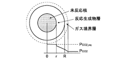
- FIG. 2 is a schematic diagram of an unreacted nucleus model used in the simulation of the above embodiment.
- FIG. 3 is a graph showing the relationship between the O 2 concentration of the calciner outlet exhaust gas and the sensible heat of the cooler exhaust.
- FIG. 4 is a graph showing the relationship between the O 2 concentration of the calciner outlet exhaust gas and the sensible heat of the preheater exhaust gas.
- FIG. 5 is a graph showing the relationship between the O 2 concentration of the calciner outlet exhaust gas and the calorific value.
- FIG. 6 is a graph showing the relationship between the O 2 concentration of the preheater outlet exhaust gas and the calorific value.
- the cement manufacturing facility includes a preheater 1 for preheating cement raw material, and an extraction from the preheater 1. Discharged from the calcining furnace 2 for calcining at least a part of the cement raw material, the cement kiln 3 for calcining the cement raw material after passing through the pre-heater 1 and the calcining furnace 2 to form a cement clinker, and the cement kiln 3 It is comprised roughly from the cooler 4 which cools a cement clinker.
- the preheater 1 is composed of a plurality of (four stages in the figure) cyclones 1a to 1d connected in the vertical direction.
- the particle size and components are adjusted in the raw material process, and the supply line 5 is changed to the uppermost cyclone 1a.
- This is a facility for preheating the supplied cement raw material with gas discharged at high temperature from the cement kiln 3 in the process of sequentially feeding the supplied cement raw material to the lower cyclones 1b to 1d.
- the raw material charged into the uppermost cyclone 1a at a temperature of about 80 ° C. reaches a temperature of 800 ° C. or higher in the lowermost cyclone 1d, and decarboxylation of limestone occurs in addition to preheating.
- the preheater exhaust gas exhaust line 6 exhausted from the uppermost cyclone 1a is provided with a fan (not shown), and the preheater exhaust gas is exhausted outside the system by the suction of the fan. .
- the combustion exhaust gas discharged from the cement kiln 3 and the calcining furnace 2 and CO 2 generated by decarboxylation of the raw material are heated between the cement raw material and the heat between the lowermost cyclone 1d and the uppermost cyclone 1a.
- the gas is discharged out of the system after replacement, and the exhaust line 6 is provided with an O 2 concentration meter 6a for measuring the O 2 concentration (second O 2 concentration) of the preheater exhaust gas.
- This sensible heat of the preheater exhaust gas affects the heat intensity, which is the heat consumption of the entire system, as a heat loss.
- the calcining furnace 2 performs decarboxylation by separating the cement raw material heated to the preheater 1c from the line 7 in order to reduce the heat load in the cement kiln 3.
- pulverized coal (first fuel) 8 charged into the furnace is combusted by the high temperature tertiary air 10 collected from the cooler 4 through the exhaust line 9, and heats the cement raw material.
- the cement raw material, unburned pulverized coal and exhaust gas discharged from the calcining furnace 2 are introduced into the lowermost cyclone 1d of the preheater 1 via the line 17, and the line 17 Is provided with an O 2 concentration meter 2 a for measuring the O 2 concentration (first O 2 concentration) of the exhaust gas from the calciner 2.
- the exhaust line 9 is provided with a flow rate adjusting valve 11 for controlling the flow rate of the tertiary air 10.
- the cement kiln 3 is a cylindrical member that is driven to rotate around an axis, and the kiln butt portion 3a is supplied with the raw material heated in the preheater 1 and the calcining furnace 2 and provided in the kiln front 3b.
- Pulverized coal (second fuel) 13 is supplied from the main burner 12 together with primary air for fuel so that the inside is maintained at 1450 ° C. necessary for firing the cement raw material by the radiation of the combustion gas and the flame. It has become.
- the input amount of the above pulverized coal is adjusted so that the decarbonation of the cement raw material and the clinker firing reaction can be performed, and the fine powder Combustion secondary air 15 supplied from the cooler 4 and the air volume of the primary air for combustion so that the charcoal is completely burned and the O 2 concentration of the exhaust gas in the kiln bottom portion 3a becomes a predetermined value.
- the air volume is controlled.
- the cooler 4 is for cooling the clinker discharged from the cement kiln 3, and the cooling air 14 for rapidly cooling the clinker is supplied to the bottom of the cooler 4.
- the air 14 is supplied in a certain amount corresponding to the amount of clinker to be manufactured.
- the clinker cooled in the cooler 4 is discharged at about 150 ° C. at the cooler outlet.
- the air 14 used for cooling becomes high temperature by heat exchange with the clinker, a part is supplied to the cement kiln 3 as secondary air 15 for combustion assistance in the cement kiln 3, and the other part is the above-mentioned.
- the remaining portion 16 is exhausted to the outside by a fan provided in an exhaust line (not shown).
- the exhaust gas from the cooler 4 also has an influence on the calorific value as a sensible heat.
- the first O 2 concentration measured by the O 2 concentration meter 2a at the exhaust gas outlet of the calcining furnace 2 in advance and the supply amount of pulverized coal 8, 13 relationship between the determined the amount of heat intensity, as well as the relationship between the second O 2 concentration and the amount of heat intensity which is measured in the exhaust gas outlet of the preheater 1 by O 2 concentration meter 6a is demanded.
- the amount of the tertiary air 10 supplied from the cooler 4 to the calciner 2 and the amount of exhaust 16 directly exhausted from the cooler 4 are controlled by controlling the number and the opening degree of the flow rate adjusting valve 11 provided in the exhaust line 9. Has been adjusted.
- each facility is broken down into units called unit operations.
- unit operations For example, in the case of a cyclone, a separator, a heat exchanger, a reactor, etc. These were arranged as shown in the circuit diagram, solid (powder) and gas flow (stream) were connected, and iterative calculation was performed until convergence was finally achieved, thereby obtaining a solution.
- This process simulation was performed using Aspen Plus v7.2 from Aspen Tech, which is a general-purpose process simulation software.
- reaction rate model was introduced in the calcining furnace 2 where the decarbonation of the cement raw material and the combustion of the pulverized coal 8 occur and the cyclone 1d at the lowest stage.
- an unreacted nuclear model was adopted as a reaction model for raw materials.
- this unreacted nucleus model is a model in which an unreacted portion (unreacted nucleus) is present inside the particle and a reaction product layer is formed on the outside thereof. Since the reaction rate varies depending on the diameter of unreacted nuclei, it is possible to perform calculation in consideration of the change in reaction rate due to the reaction rate.
- the cement raw material it was set as the composition which can manufacture the clinker of normal Portland cement.
- CaCO 3 contained in the cement raw material is decarboxylated and changed to CaO. This decarboxylation reaction was performed on the surface of unreacted CaCO 3 , and the grain model was adopted assuming that the reaction interface was proportional to the surface area.
- the equilibrium partial pressure P CO2 — eq of CO 2 at a predetermined temperature was obtained and corrected by the ratio to the CO 2 partial pressure in the calculation.
- the reaction amount was calculated by the product of the reaction rate coefficient and the residence time as shown in the following equation.
- the temperature dependence of the equilibrium partial pressure is measured by a thermobalance or the like, for example, a literature (“Thermodynamic evaluation and optimization of the (Ca + C + O + S) system” D. Lindberg and P. Chartrand, J. Chem. Thermo., 41, 2009). ) Etc. can be used.
- the preheater 1 is a cyclone 1a to 1d connected in the vertical direction, and preheats the cement material with the combustion gas discharged from the cement kiln 2 at a high temperature.
- the cement raw material charged into the uppermost cyclone 1a at a temperature of about 80 ° C. reaches a temperature of 800 ° C. or higher in the lowermost cyclone 1d, and in addition to preheating, decarboxylation of CaCO 3 occurs.
- a certain amount of cement raw material and a certain amount of pulverized coal corresponding thereto are supplied, and the air volume of the tertiary air 10 for combustion is adjusted.
- decarbonation in this calcining furnace 2 is supposed to react as described above, and pulverized coal can be obtained from literature ("A random pore model for fluid-solid reactions: I. Isothermal, kinetic control", S. K. Bhatia, D. D. Perlmutter, AIChE Journal vol26, 3 1980), ("Coal gasification reaction modeling ⁇ ⁇ Coal char gasification rate and shape change model", Sugaya Shitani, Power Research Institute report 2003) And burned.
- the amount of pulverized coal input is adjusted so that the cement raw material becomes a clinker of 1450 ° C. (calcining zone temperature), and the air volume of the secondary air 15 that assists combustion burns pulverized coal.
- the oxygen concentration in the exhaust gas in the kiln bottom portion 3a is determined to be 2%.
- a value of 1450 ° C. is a value that is said to cause a clinker firing reaction in general
- a value of 2% of exhaust gas oxygen is an operation in a cement production facility of a type in which the cement kiln 3 and the calciner 2 are separated. It is a general target value for time.
- ⁇ Rate of heat received by the raw material from the combustion gas
- Q combustion_air Sensible heat of the combustion gas [kcal / hr]
- ⁇ 0.4.
- the heat exchange between the clinker and the cooling air 14 in the cooler 4 was calculated as a cross flow with the clinker as a fixed layer.
- the heat transfer coefficient was derived by the ranz-marshall equation.
- the heat transfer amount Q is determined by referring to the literature ("Process Kiln", Japan Powder Industrial Technology Association, Nikkan Kogyo Shimbun, 1985), and obtaining the heat transfer amount q between the particles and the fluid per unit fixed bed volume.
- Cross-flow heat exchange obtained from the literature (“mean temperature difference and temperature efficiency for shell and tube heat exchangers connected in series with two tube passes per shell pass”, Dodd, R., IChemE vol.58, 1980) Calculation was performed by multiplying the correction coefficient F and the volume V of the particles.
- the clinker particle size was 20 mm, and the layer thickness of the clinker deposited inside the cooler was set to a thickness matched to the actual machine.
- the combustion management of the pulverized coal 8 is performed based on the O 2 concentration in the exhaust gas from the calciner 2. Therefore, according to actual operation, calculation was performed for the case where the amount of the tertiary air 10 was adjusted so that the O 2 concentration in the exhaust gas of the calciner 2 was 1.5% to 5%.
- FIG. 5 shows a change in the calorific value unit when the amount of the tertiary air 10 is adjusted so that the O 2 concentration in the exhaust gas of the calciner 2 is 1.5% to 5%. Also, O 2 concentration in the exhaust gas from the preheater 1 not only O 2 concentration in the exhaust gas sent from the calciner 2, also affected by the O 2 concentration in the exhaust gas from a cement kiln 3.
- FIG. 6 shows changes in the O 2 concentration in the exhaust gas at the outlet of the preheater 1 and the calorific value.
- auxiliary combustion rate (the amount of heat of the fuel input to the calciner 2) / (the amount of heat of the fuel input to the cement kiln 3 + the amount of heat of the fuel input to the calciner 2).
- the relationship shown in FIG. 5 and FIG. 6 is obtained in advance, and the first and second oxygen concentrations are measured during operation, and both of these include a value of the oxygen concentration at which the calorific value is minimized.
- Adjusting the air volume of the tertiary air supplied to the calciner and the air volume of the exhaust 16 from the cooler 4 by controlling the fan and the flow rate adjusting valve 11 provided in the exhaust line from the cooler 4 so as to be inside.
- both the combustion in the calcining furnace 2 and the basic unit of calorie can be optimized simultaneously.
- the O 2 concentration of the exhaust gas at the calciner outlet can be adjusted between approximately 2% and 4%, and the O 2 concentration of the preheater exhaust gas can be adjusted between approximately 0.5% and 2%. desirable.
Landscapes
- Engineering & Computer Science (AREA)
- Chemical & Material Sciences (AREA)
- Ceramic Engineering (AREA)
- Mechanical Engineering (AREA)
- General Engineering & Computer Science (AREA)
- Materials Engineering (AREA)
- Organic Chemistry (AREA)
- Structural Engineering (AREA)
- Physics & Mathematics (AREA)
- Thermal Sciences (AREA)
- Combustion & Propulsion (AREA)
- Environmental & Geological Engineering (AREA)
- Furnace Details (AREA)
- Curing Cements, Concrete, And Artificial Stone (AREA)
- Muffle Furnaces And Rotary Kilns (AREA)
Abstract
Description
他方、通常仮焼炉の排ガス出口には、当該仮焼炉内における燃焼状態を確認するために酸素(O2)濃度計が設置されている。

k:反応速度[1/s]
A:2.2×10⁸[1/s]
E:2.0×10⁵[J/mol]
R:気体定数8.314
T:温度[K]
X:脱炭酸率(質量基準)
PCO2:計算におけるCO2分圧
PCO2_eq:所定温度でのCO2の平衡分圧

Qcombustion_air:燃焼ガスの顕熱[kcal/hr]
本実施形態においては、α=0.4とした。

ここで
Q:伝熱量[J/s]
q:単位体積あたりの伝熱量[J/m3s]
F:補正係数
V:粒子体積[m3]
h:伝熱係数[J/m2sK]
a:粒子の比表面積[1/m]
2 仮焼炉
2a、6a O2濃度計
3 セメントキルン
4 クーラー
8 微粉炭(第1の燃料)
10 3次空気
11 流量調整弁
13 微粉炭(第2の燃料)
15 2次空気
16 排気
Claims (2)
- セメント原料を予熱するプレヒーターと、このプレヒーターから抜き出された上記セメント原料の少なくとも一部を仮焼成する仮焼炉と、上記プレヒーターおよび仮焼炉を経た上記セメント原料を焼成してセメントクリンカとするセメントキルンと、このセメントキルンから排出された上記セメントクリンカを冷却するクーラーとを備え、上記仮焼炉に、導入される上記セメント原料を仮焼するに必要な量の第1の燃料を供給し、上記セメントキルンに、内部を焼成温度に保持するに必要な量の第2の燃料を燃焼用の1次空気と共に供給し、かつ上記クーラーに、上記セメントクリンカを冷却するための一定量の空気を導入し、当該空気のうちの一部を上記第2の燃料の燃焼を補助する2次空気として上記セメントキルンに供給し、他の一部を上記第1の燃料を燃焼させる3次空気として上記仮焼炉に供給するとともに、残部を当該クーラーから排気するセメント製造設備の運転方法において、
予め上記仮焼炉の排ガス出口における第1の酸素濃度と上記第1および第2の燃料によって決定される熱量原単位との関係、並びに上記プレヒーターの排ガス出口における第2の酸素濃度と上記熱量原単位との関係を求めておき、
上記第1および第2の酸素濃度が、いずれも上記熱量原単位が最小となる上記酸素濃度の値を含む範囲内になるように、上記3次空気および上記クーラーからの排気の風量を調整することを特徴とするセメント製造設備の運転方法。 - 上記仮焼炉に、上記第1の燃料を一定の供給量で供給するとともに、上記セメントキルンに、上記第2の燃料を上記焼成温度に保持するために必要な供給量に調整しつつ供給することを特徴とする請求項1に記載のセメント製造設備の運転方法。
Priority Applications (3)
| Application Number | Priority Date | Filing Date | Title |
|---|---|---|---|
| AU2014326102A AU2014326102B2 (en) | 2013-09-30 | 2014-06-30 | Method for operating cement production facility |
| US14/916,465 US10131576B2 (en) | 2013-09-30 | 2014-06-30 | Method for operating cement plant |
| CN201480054046.XA CN105579415B (zh) | 2013-09-30 | 2014-06-30 | 水泥制造设备的运转方法 |
Applications Claiming Priority (2)
| Application Number | Priority Date | Filing Date | Title |
|---|---|---|---|
| JP2013-204005 | 2013-09-30 | ||
| JP2013204005 | 2013-09-30 |
Publications (1)
| Publication Number | Publication Date |
|---|---|
| WO2015045227A1 true WO2015045227A1 (ja) | 2015-04-02 |
Family
ID=52742410
Family Applications (1)
| Application Number | Title | Priority Date | Filing Date |
|---|---|---|---|
| PCT/JP2014/003457 Ceased WO2015045227A1 (ja) | 2013-09-30 | 2014-06-30 | セメント製造設備の運転方法 |
Country Status (6)
| Country | Link |
|---|---|
| US (1) | US10131576B2 (ja) |
| JP (1) | JP6327016B2 (ja) |
| CN (1) | CN105579415B (ja) |
| AU (1) | AU2014326102B2 (ja) |
| MY (1) | MY176197A (ja) |
| WO (1) | WO2015045227A1 (ja) |
Cited By (2)
| Publication number | Priority date | Publication date | Assignee | Title |
|---|---|---|---|---|
| CN115164610A (zh) * | 2022-05-23 | 2022-10-11 | 华中科技大学 | 一种基于co/o2的水泥分解炉燃烧优化方法及系统 |
| CN115183593A (zh) * | 2022-07-06 | 2022-10-14 | 天津水泥工业设计研究院有限公司 | 一种可实现节能降耗的水泥窑全氧燃烧多介质分区供风篦冷机系统 |
Families Citing this family (5)
| Publication number | Priority date | Publication date | Assignee | Title |
|---|---|---|---|---|
| FI127753B (en) * | 2017-06-09 | 2019-01-31 | Bioshare Ab | Recycling of chemicals from fuel streams |
| DE102018215348A1 (de) * | 2018-09-10 | 2020-03-12 | Thyssenkrupp Ag | Kühler zum Kühlen von Klinker und Verfahren zum Betreiben eines Kühlers zum Kühlen von Klinker |
| EP4247767B1 (de) | 2021-02-12 | 2024-01-17 | thyssenkrupp Polysius GmbH | Verfahren zur thermischen behandlung von flugfähigem rohmaterial |
| BE1029102B1 (de) * | 2021-02-12 | 2022-09-12 | Thyssenkrupp Ag | Anlage und Verfahren zur thermischen Behandlung von flugfähigem Rohmaterial |
| CN115470720B (zh) * | 2022-08-26 | 2025-07-15 | 华中科技大学 | 一种水泥窑协同处置有机固废工艺的模拟及优化方法 |
Citations (6)
| Publication number | Priority date | Publication date | Assignee | Title |
|---|---|---|---|---|
| JPS52931A (en) * | 1975-06-24 | 1977-01-06 | Onoda Cement Co Ltd | Method of controlling apparatus for baking cement provided with complex ventilation system |
| JPS6374944A (ja) * | 1986-09-17 | 1988-04-05 | 株式会社神戸製鋼所 | 粉末原料焼成装置 |
| JP2000281400A (ja) * | 1999-03-16 | 2000-10-10 | L'air Liquide | 酸素富化用キルン |
| JP2001524449A (ja) * | 1997-12-02 | 2001-12-04 | セメント・ペットコプティマイザー・カンパニー | 最終産物の硫黄含有量の分析によるセメントクリンカー製造の制御 |
| JP2009215097A (ja) * | 2008-03-07 | 2009-09-24 | Ube Ind Ltd | セメント製造装置の運転方法 |
| JP2010235334A (ja) * | 2009-03-30 | 2010-10-21 | Taiheiyo Cement Corp | 水銀水溶化方法 |
Family Cites Families (10)
| Publication number | Priority date | Publication date | Assignee | Title |
|---|---|---|---|---|
| US3366374A (en) * | 1965-11-23 | 1968-01-30 | Leeds & Northrup Co | Method and apparatus for control of rotary kiln exit gas conditions |
| JPS5238569B2 (ja) * | 1973-07-03 | 1977-09-29 | ||
| JPS5347497Y2 (ja) * | 1974-02-19 | 1978-11-14 | ||
| JPS5849648A (ja) | 1981-09-18 | 1983-03-23 | 日本セメント株式会社 | セメント原料仮焼方法及び装置 |
| US6488765B1 (en) * | 1997-07-30 | 2002-12-03 | Cemex, Inc. | Oxygen enrichment of cement kiln system combustion |
| FR2795808B1 (fr) * | 1999-07-02 | 2001-09-14 | Air Liquide | Procede de combustion, applicable a la fabrication de ciment |
| JP4501554B2 (ja) * | 2004-06-30 | 2010-07-14 | 三菱マテリアル株式会社 | シミュレーションプログラムおよび記憶媒体 |
| JP4645441B2 (ja) * | 2005-12-27 | 2011-03-09 | 三菱マテリアル株式会社 | セメントキルンの運転制御方法およびセメントの製造方法 |
| EP2289858B1 (en) * | 2008-05-07 | 2015-06-24 | Mitsubishi Materials Corporation | Method and apparatus for recovering co2 gas in cement production equipment |
| DE102008036088B4 (de) * | 2008-08-04 | 2012-06-28 | Thyssenkrupp Polysius Ag | Verfahren zum Betreiben einer Zementanlage |
-
2014
- 2014-06-30 AU AU2014326102A patent/AU2014326102B2/en not_active Ceased
- 2014-06-30 MY MYPI2016700272A patent/MY176197A/en unknown
- 2014-06-30 JP JP2014133477A patent/JP6327016B2/ja active Active
- 2014-06-30 WO PCT/JP2014/003457 patent/WO2015045227A1/ja not_active Ceased
- 2014-06-30 CN CN201480054046.XA patent/CN105579415B/zh not_active Expired - Fee Related
- 2014-06-30 US US14/916,465 patent/US10131576B2/en active Active
Patent Citations (6)
| Publication number | Priority date | Publication date | Assignee | Title |
|---|---|---|---|---|
| JPS52931A (en) * | 1975-06-24 | 1977-01-06 | Onoda Cement Co Ltd | Method of controlling apparatus for baking cement provided with complex ventilation system |
| JPS6374944A (ja) * | 1986-09-17 | 1988-04-05 | 株式会社神戸製鋼所 | 粉末原料焼成装置 |
| JP2001524449A (ja) * | 1997-12-02 | 2001-12-04 | セメント・ペットコプティマイザー・カンパニー | 最終産物の硫黄含有量の分析によるセメントクリンカー製造の制御 |
| JP2000281400A (ja) * | 1999-03-16 | 2000-10-10 | L'air Liquide | 酸素富化用キルン |
| JP2009215097A (ja) * | 2008-03-07 | 2009-09-24 | Ube Ind Ltd | セメント製造装置の運転方法 |
| JP2010235334A (ja) * | 2009-03-30 | 2010-10-21 | Taiheiyo Cement Corp | 水銀水溶化方法 |
Cited By (4)
| Publication number | Priority date | Publication date | Assignee | Title |
|---|---|---|---|---|
| CN115164610A (zh) * | 2022-05-23 | 2022-10-11 | 华中科技大学 | 一种基于co/o2的水泥分解炉燃烧优化方法及系统 |
| CN115164610B (zh) * | 2022-05-23 | 2024-06-11 | 华中科技大学 | 一种基于co/o2的水泥分解炉燃烧优化方法及系统 |
| CN115183593A (zh) * | 2022-07-06 | 2022-10-14 | 天津水泥工业设计研究院有限公司 | 一种可实现节能降耗的水泥窑全氧燃烧多介质分区供风篦冷机系统 |
| CN115183593B (zh) * | 2022-07-06 | 2024-06-07 | 天津水泥工业设计研究院有限公司 | 一种可实现节能降耗的水泥窑全氧燃烧多介质分区供风篦冷机系统 |
Also Published As
| Publication number | Publication date |
|---|---|
| CN105579415A (zh) | 2016-05-11 |
| AU2014326102A1 (en) | 2016-02-25 |
| JP2015091741A (ja) | 2015-05-14 |
| MY176197A (en) | 2020-07-24 |
| JP6327016B2 (ja) | 2018-05-23 |
| US10131576B2 (en) | 2018-11-20 |
| AU2014326102B2 (en) | 2017-06-29 |
| CN105579415B (zh) | 2017-09-22 |
| US20160214893A1 (en) | 2016-07-28 |
Similar Documents
| Publication | Publication Date | Title |
|---|---|---|
| JP6327016B2 (ja) | セメント製造設備の運転方法 | |
| RU2466950C2 (ru) | Способ производства цемента | |
| US10570061B2 (en) | Process for manufacture of Portland cement | |
| WO2009136485A1 (ja) | セメント製造設備におけるco2ガスの回収方法および回収設備 | |
| RU2471133C2 (ru) | Способ и установка по производству цементного клинкера с одновременной выработкой электроэнергии | |
| US9914663B2 (en) | Manufacturing facility for quicklime, and manufacturing facility and manufacturing process for slaked lime | |
| CN102472580A (zh) | 在装置中制造水泥熔块的方法以及制备水泥熔块的装置 | |
| US3519254A (en) | Method and apparatus for the control of burner heat distribution | |
| JP5615818B2 (ja) | セメント・プラントおよびセメント・プラントを運転する方法 | |
| JP7565995B2 (ja) | 二酸化炭素製造装置、二酸化炭素製造方法、二酸化炭素製造装置の設計方法 | |
| JP4730393B2 (ja) | セメント製造設備におけるco2ガスの回収方法および回収設備 | |
| WO2022126410A1 (zh) | 一种低能耗碳富集水泥生产系统及生产水泥熟料的方法 | |
| DK155726B (da) | Fremgangsmaade til fremstilling af cementklinker | |
| JP5225904B2 (ja) | 燃焼状態監視方法 | |
| Akgun | Investigaton of energy saving and NOx reduction possibilities in a rotary cement kiln | |
| JP5911091B2 (ja) | セメント焼成装置 | |
| JP4730455B2 (ja) | セメント製造設備におけるco2ガスの回収方法および回収設備 | |
| RU2547195C1 (ru) | Способ получения портландцементного клинкера (варианты) | |
| JP5803588B2 (ja) | クリンカ製造装置 | |
| JP7020253B2 (ja) | 二酸化炭素製造装置、二酸化炭素製造方法、二酸化炭素製造装置の設計方法 | |
| JP2018118861A (ja) | セメントの製造方法 | |
| JP2005214445A (ja) | 燃料の燃焼方法及び燃焼装置 | |
| Muşat | PERFORMANCE ENHANCEMENT TYPE CHAMBER HEATING FURNACES BY EQUIPPING THEM WITH THE NEW AIR PREHEATER RADIATION PAR-MD | |
| HRP20120868A2 (hr) | Peä† za proizvodnju vapna | |
| HRP20151206B1 (hr) | Peć za proizvodnju vapna na alternativna goriva |
Legal Events
| Date | Code | Title | Description |
|---|---|---|---|
| WWE | Wipo information: entry into national phase |
Ref document number: 201480054046.X Country of ref document: CN |
|
| 121 | Ep: the epo has been informed by wipo that ep was designated in this application |
Ref document number: 14849279 Country of ref document: EP Kind code of ref document: A1 |
|
| WWE | Wipo information: entry into national phase |
Ref document number: IDP00201600880 Country of ref document: ID |
|
| ENP | Entry into the national phase |
Ref document number: 2014326102 Country of ref document: AU Date of ref document: 20140630 Kind code of ref document: A |
|
| WWE | Wipo information: entry into national phase |
Ref document number: 14916465 Country of ref document: US |
|
| NENP | Non-entry into the national phase |
Ref country code: DE |
|
| 122 | Ep: pct application non-entry in european phase |
Ref document number: 14849279 Country of ref document: EP Kind code of ref document: A1 |