WO2015044978A1 - 情報処理装置、撮影システム、情報処理方法及びプログラム - Google Patents
情報処理装置、撮影システム、情報処理方法及びプログラム Download PDFInfo
- Publication number
- WO2015044978A1 WO2015044978A1 PCT/JP2013/005695 JP2013005695W WO2015044978A1 WO 2015044978 A1 WO2015044978 A1 WO 2015044978A1 JP 2013005695 W JP2013005695 W JP 2013005695W WO 2015044978 A1 WO2015044978 A1 WO 2015044978A1
- Authority
- WO
- WIPO (PCT)
- Prior art keywords
- blood vessel
- transmission
- image
- frame
- reception unit
- Prior art date
- Legal status (The legal status is an assumption and is not a legal conclusion. Google has not performed a legal analysis and makes no representation as to the accuracy of the status listed.)
- Ceased
Links
Images

Classifications
-
- A—HUMAN NECESSITIES
- A61—MEDICAL OR VETERINARY SCIENCE; HYGIENE
- A61B—DIAGNOSIS; SURGERY; IDENTIFICATION
- A61B6/00—Apparatus or devices for radiation diagnosis; Apparatus or devices for radiation diagnosis combined with radiation therapy equipment
- A61B6/50—Apparatus or devices for radiation diagnosis; Apparatus or devices for radiation diagnosis combined with radiation therapy equipment specially adapted for specific body parts; specially adapted for specific clinical applications
- A61B6/504—Apparatus or devices for radiation diagnosis; Apparatus or devices for radiation diagnosis combined with radiation therapy equipment specially adapted for specific body parts; specially adapted for specific clinical applications for diagnosis of blood vessels, e.g. by angiography
-
- A—HUMAN NECESSITIES
- A61—MEDICAL OR VETERINARY SCIENCE; HYGIENE
- A61B—DIAGNOSIS; SURGERY; IDENTIFICATION
- A61B1/00—Instruments for performing medical examinations of the interior of cavities or tubes of the body by visual or photographical inspection, e.g. endoscopes; Illuminating arrangements therefor
- A61B1/00002—Operational features of endoscopes
- A61B1/00004—Operational features of endoscopes characterised by electronic signal processing
- A61B1/00006—Operational features of endoscopes characterised by electronic signal processing of control signals
-
- A—HUMAN NECESSITIES
- A61—MEDICAL OR VETERINARY SCIENCE; HYGIENE
- A61B—DIAGNOSIS; SURGERY; IDENTIFICATION
- A61B1/00—Instruments for performing medical examinations of the interior of cavities or tubes of the body by visual or photographical inspection, e.g. endoscopes; Illuminating arrangements therefor
- A61B1/00002—Operational features of endoscopes
- A61B1/00004—Operational features of endoscopes characterised by electronic signal processing
- A61B1/00009—Operational features of endoscopes characterised by electronic signal processing of image signals during a use of endoscope
- A61B1/000094—Operational features of endoscopes characterised by electronic signal processing of image signals during a use of endoscope extracting biological structures
-
- A—HUMAN NECESSITIES
- A61—MEDICAL OR VETERINARY SCIENCE; HYGIENE
- A61B—DIAGNOSIS; SURGERY; IDENTIFICATION
- A61B1/00—Instruments for performing medical examinations of the interior of cavities or tubes of the body by visual or photographical inspection, e.g. endoscopes; Illuminating arrangements therefor
- A61B1/313—Instruments for performing medical examinations of the interior of cavities or tubes of the body by visual or photographical inspection, e.g. endoscopes; Illuminating arrangements therefor for introducing through surgical openings, e.g. laparoscopes
- A61B1/3137—Instruments for performing medical examinations of the interior of cavities or tubes of the body by visual or photographical inspection, e.g. endoscopes; Illuminating arrangements therefor for introducing through surgical openings, e.g. laparoscopes for examination of the interior of blood vessels
-
- A—HUMAN NECESSITIES
- A61—MEDICAL OR VETERINARY SCIENCE; HYGIENE
- A61B—DIAGNOSIS; SURGERY; IDENTIFICATION
- A61B6/00—Apparatus or devices for radiation diagnosis; Apparatus or devices for radiation diagnosis combined with radiation therapy equipment
- A61B6/12—Arrangements for detecting or locating foreign bodies
-
- A—HUMAN NECESSITIES
- A61—MEDICAL OR VETERINARY SCIENCE; HYGIENE
- A61B—DIAGNOSIS; SURGERY; IDENTIFICATION
- A61B8/00—Diagnosis using ultrasonic, sonic or infrasonic waves
- A61B8/12—Diagnosis using ultrasonic, sonic or infrasonic waves in body cavities or body tracts, e.g. by using catheters
Definitions
- the present invention relates to an information processing apparatus, an imaging system, an information processing method, and a program, and more particularly, to imaging for medical diagnosis.
- an intravascular medical practice using a catheter including a balloon, a stent, or the like is usually performed while referring to a diagnostic image.
- stenosis or occlusion of blood vessels can be confirmed by observing fluoroscopic images, for example, X-ray images, taken continuously by angiography (angio, angio).
- fluoroscopic images for example, X-ray images, taken continuously by angiography (angio, angio).
- angio angio
- angio angio
- OCT optical interference diagnostic imaging apparatus
- OFDI optical interference diagnostic imaging apparatus
- fluoroscopic images and tomographic images are mainly used for diagnosis before surgery and confirmation of therapeutic effect after surgery.
- the operator when performing treatment to insert a stent into a blood vessel and widen the stenosis of the blood vessel, the operator (operator) confirms the overall shape of the target coronary artery from the X-ray image and specifies the stenosis of the blood vessel. .
- the surgeon grasps the pathological condition in the blood vessel using the tomographic image in the stenosis, and finally determines the placement position and size of the stent.
- Patent Document 1 describes that the position of a transmission / reception unit used for imaging possessed by an IVUS probe inserted into a subject is displayed on an X-ray image.
- Patent Document 2 discloses a method for detecting a moving position of a transmission / reception unit of an ultrasonic probe from an X-ray fluoroscopic image.
- Patent Document 2 further discloses recording an ultrasonic image at a predetermined position and displaying the recorded ultrasonic image in accordance with the position designation by the user.
- the operator may desire to re-photograph the tomographic image when a finer tomographic image is desired.
- due to the difficulty of position designation it is not easy to quickly move the transmission / reception unit of the probe to the blood vessel position desired by the operator.
- An object of the present invention is to quickly move a transmission / reception unit included in a probe of a tomography apparatus to a blood vessel position desired by an operator.
- an information processing apparatus of the present invention comprises the following arrangement. That is, A probe having a transmission / reception unit is inserted into a blood vessel, and connected to a tomography apparatus that takes a tomographic image of the blood vessel using the transmission / reception unit while controlling the position of the transmission / reception unit in the blood vessel length direction.
- First acquisition means for acquiring a position of an image of a transmission / reception unit included in each frame of a perspective image of a blood vessel composed of one or more frames taken while the probe is inserted into the blood vessel
- Display control means for displaying at least one of the frames of the fluoroscopic image on a display means
- Second acquisition means for acquiring a blood vessel position designated by a user on a frame of the fluoroscopic image displayed on the display means
- a specifying means for specifying a frame of the fluoroscopic image including an image of a transmission / reception unit located closer to a blood vessel position specified by the user;
- Transmitting means for transmitting an instruction to move the transmission / reception unit to the tomographic imaging apparatus so that the position of the transmission / reception unit when the frame is imaged is similar to the position
- the transmission / reception unit of the probe of the tomography apparatus can be quickly moved to the blood vessel position desired by the operator.
- FIG. 1 is a diagram illustrating an example of the configuration of the information processing apparatus according to the first embodiment.
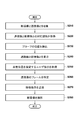
- FIG. 2 is a flowchart illustrating an example of processing according to the first embodiment.
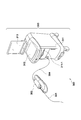
- FIG. 3 is a diagram illustrating an example of the configuration of the OFDI apparatus.
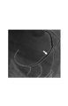
- FIG. 4 is a diagram illustrating an example of a method for specifying a blood vessel position on a fluoroscopic image.
- FIG. 1 is a block diagram illustrating an example of the configuration of the information processing apparatus 100 according to the present embodiment.
- the information processing apparatus 100 according to the present embodiment includes an image collection unit 110, a correspondence acquisition unit 120, a detection unit 125, a user instruction acquisition unit 130, a display control unit 140, a frame specification unit 145, and an instruction transmission unit. 150.
- the information processing apparatus 100 is communicably connected to the tomographic imaging apparatus 170 and the display apparatus 190, and can control these operations.
- the image collection unit 110 collects tomographic images and fluoroscopic images of blood vessels.
- the type of tomographic image of the blood vessel is not particularly limited, and may be, for example, an ultrasonic tomographic image or an optical tomographic image.
- the tomographic image collected by the image collection unit 110 is taken by inserting a probe having a transmission / reception unit into a blood vessel.
- the fluoroscopic images collected by the image collecting unit 110 are taken while taking a tomographic image of a blood vessel by inserting a probe having a transmission / reception unit into the blood vessel. This transmission / reception unit is used to take a tomographic image of a blood vessel at the position of the transmission / reception unit.
- the transceiver transmits and receives diagnostic waves.
- the transmission / reception unit transmits / receives ultrasonic waves when imaging an ultrasonic tomogram
- the transmission / reception unit transmits / receives light when imaging an optical tomogram.
- the image collecting unit 110 is connected to the tomographic imaging apparatus 170 and the fluoroscopic imaging apparatus 180, and collects a tomographic image and a fluoroscopic image from these apparatuses. These devices usually acquire a transverse cross-sectional image in the blood vessel radial direction, but a vertical cross-sectional image in the blood vessel length direction can also be obtained from the cross-sectional image.
- the ultrasonic tomographic image can be acquired by, for example, an intravascular ultrasonic diagnostic apparatus (IVUS: Intra Vascular Ultra Sound).
- IVUS Intra Vascular Ultra Sound
- the optical tomographic image can be acquired by, for example, an optical coherence tomography diagnostic apparatus (OCT: Optical Coherence Tomography) or an optical interference image diagnostic apparatus (OFDI: Optical Frequency Imaging) using a wavelength sweep.
- OCT optical coherence tomography diagnostic apparatus
- OFDI optical interference image diagnostic apparatus
- the tomographic image collected by the image collecting unit 110 is composed of a plurality of frames.
- an optical probe of an OFDI apparatus is inserted into a blood vessel such as a coronary artery through a catheter, and a tomographic image is continuously captured using a transmission / reception unit of the optical probe while pulling the optical probe.
- a tomographic image composed of frames can be obtained.
- the type of fluoroscopic image of the blood vessel is not particularly limited, but may be an X-ray image taken using a contrast agent by an angiography method, for example. That is, by continuously capturing X-ray images while pulling the optical probe of the OFDI apparatus, it is possible to obtain a perspective image composed of a plurality of frames.
- the OFDI apparatus 300 includes a probe unit 301, a scanner / pullback unit 302, and an operation control device 303.
- the scanner / pullback unit 302 and the operation control device 303 are connected via a signal line 304 so that various signals can be transmitted. ing.
- the probe unit 301 is directly inserted into a blood vessel and continuously transmits the transmitted light (measurement light) into the blood vessel, and includes an optical transmission / reception unit that continuously receives reflected light from the blood vessel. Is interpolated.
- an imaging core including a transmission / reception unit is provided near the tip of the probe unit 301. In the OFDI apparatus 300, the state inside the blood vessel is measured by using the imaging core.
- the scanner and pullback unit 302 is detachably attached to the probe unit 301, and operates in the axial direction and rotational direction in the blood vessel of the imaging core inserted in the probe unit 301 by driving a built-in motor. It prescribes.
- the scanner and pullback unit 302 can control the position of the transmission / reception unit in the blood vessel length direction by controlling the insertion length of the probe into the blood vessel, for example, in accordance with an instruction from the operation control device 303.
- the probe unit 301 measures a state inside the blood vessel at a position controlled by the scanner and the pull back unit 302, and a tomographic image is generated according to the measurement result.
- the scanner and pullback unit 302 acquires the reflected light received by the optical transmission / reception unit and transmits it to the operation control device 303.
- the operation control device 303 performs a function for inputting various set values and processes data obtained by the measurement to generate a tomographic image, and generates each frame (intravascular vessel) of the generated tomographic image. Of the horizontal cross-sectional image and the vertical cross-sectional image).
- the generated tomographic image can be transmitted to the information processing apparatus 100.
- reference numeral 311 denotes a main body control unit, which generates line section images by processing line data generated based on reflected light obtained by measurement.
- Reference numeral 311-1 denotes a printer and a DVD recorder, which print out processing results in the main body control unit 311 and store them as data.
- Reference numeral 312 denotes an operation panel, and the user inputs various setting values and instructions via the operation panel 312.
- Reference numeral 313 denotes an LCD monitor as a display device, which displays a cross-sectional image generated by the main body control unit 311.
- the information processing apparatus 100 collects tomographic images and fluoroscopic images from the tomographic image and fluoroscopic image capturing apparatus.
- the information processing apparatus 100 according to the present embodiment is incorporated in the tomographic image or fluoroscopic image capturing apparatus. It may be.
- the main body control unit 311 illustrated in FIG. 3 may include each component of the information processing apparatus 100 illustrated in FIG.
- the display control unit 140 can control the display on the LCD monitor 313, and the user instruction acquisition unit 130 can acquire a user instruction from the operation panel 312.
- An imaging system including a tomographic imaging apparatus 170 that captures a tomographic image and a fluoroscopic imaging apparatus 180 that captures a fluoroscopic image may further include the information processing apparatus 100 according to the present embodiment.
- the correspondence acquisition unit 120 acquires the correspondence between each frame constituting the fluoroscopic image and each frame constituting the tomographic image. Specifically, the correspondence acquisition unit 120 determines, for each frame constituting the fluoroscopic image, a tomographic image frame that is captured substantially simultaneously with this frame.
- the method for acquiring the correspondence relationship is not particularly limited.
- the tomographic image frame photographed substantially simultaneously with the fluoroscopic image frame may be a tomographic image frame photographed within a predetermined time interval from the photographing time of the fluoroscopic image frame.
- the correspondence acquisition unit 120 can record that there is no corresponding tomographic image frame.
- the correspondence acquisition unit 120 can acquire this correspondence by image processing on a tomographic image and a fluoroscopic image.
- the correspondence acquisition unit 120 detects the position of the transmission / reception unit included in the probe from the fluoroscopic image, calculates the insertion length of the transmission / reception unit, and determines the tomographic image corresponding to the calculated insertion length. it can.
- the correspondence acquisition unit 120 can also acquire this correspondence according to the branch position of the blood vessel detected from the fluoroscopic image and the branch position of the blood vessel detected from the tomographic image.
- the correspondence acquisition unit 120 refers to the time stamp attached to each frame constituting the fluoroscopic image and the time stamp attached to each frame constituting the tomographic image to obtain this correspondence relationship. Can do.
- the correspondence acquisition unit 120 can acquire the correspondence relationship with reference to the frame rate of the fluoroscopic image and the frame rate of the tomographic image.
- the detection unit 125 detects the position of the image of the transmission / reception unit included in each frame constituting the fluoroscopic image. For example, by attaching a member having high X-ray absorption to the transmission / reception unit included in the optical probe of the OFDI apparatus, the position of the transmission / reception unit can be detected from the frame of the fluoroscopic image. In this case, the position of the transmission / reception unit is detected as a more absorbable part in the blood vessel.
- the information processing apparatus 100 does not have to include the detection unit 125.
- the image collection unit 110 may acquire information indicating the position of the transmission / reception unit in each frame constituting the fluoroscopic image together with or separately from the fluoroscopic image.
- the user instruction acquisition unit 130 acquires a user instruction for specifying a blood vessel position.
- the user instruction is given on the frame of the fluoroscopic image displayed on the display device 190.
- the user can specify a blood vessel at a predetermined position on the displayed fluoroscopic image using an input device (not shown) such as a mouse, and in this case, the user instruction acquisition unit 130 acquires the specified blood vessel position.
- FIG. 4 shows an example of designation by the user. In FIG. 4, one point on the blood vessel shown in the fluoroscopic image is designated by the mouse pointer. In FIG. 4, the position of the blood vessel is highlighted for explanation, but it is not essential to emphasize the position of the blood vessel.
- the display device 190 includes a touch screen, the user may input a position designation via the touch screen.
- the display control unit 140 causes the display device 190 to display a tomographic image and a fluoroscopic image.
- the display control unit 140 in order to enable a surgeon (operator) to make a more accurate determination, includes a frame of a tomographic image and a fluoroscopic image captured substantially simultaneously with the frame of the tomographic image. The frame is simultaneously displayed on the display device 190.
- the display control unit 140 displays the cross-sectional image on the display device 190, but can further display the vertical cross-sectional image on the display device 190. Specific processing of the display control unit 140 will be described later.
- the frame specifying unit 145 specifies a frame of a fluoroscopic image including the image of the transmitting / receiving unit located closer to the blood vessel position indicated by the user instruction acquired by the user instruction acquiring unit 130. Specific processing of the frame specifying unit 145 will be described later.
- the instruction transmission unit 150 transmits a movement instruction of the transmission / reception unit to the tomography apparatus 170.
- the instruction transmission unit 150 also transmits a tomographic image capturing instruction to the tomographic image capturing apparatus 170. Specific processing of the instruction transmission unit 150 will also be described later.
- step S210 the image collection unit 110 collects a tomographic image and a fluoroscopic image of the blood vessel as described above.
- step S220 the correspondence acquisition unit 120 acquires the correspondence relationship between the fluoroscopic image and the tomographic image of the blood vessel as described above.
- step S230 the detection unit 125 detects the position of the transmission / reception unit from each frame constituting the fluoroscopic image as described above. For example, when the frame number of the perspective image to be symmetric is k and the coordinates of the detected position of the transmission / reception unit are (x, y), the detection unit 125 records a plurality of sets of (x, y, k). .
- step S240 the display control unit 140 causes the display device 190 to simultaneously display at least one frame of the fluoroscopic image and the frame of the corresponding tomographic image.
- the method for selecting a frame to be displayed in step S240 is not particularly limited.
- the display control unit 140 may display the first frame among the frames constituting the fluoroscopic image.
- the display control unit 140 may not display the tomographic image.
- the display control unit 140 captures a tomographic image captured at the time closest to the imaging time of the perspective image frame. The frame may be displayed.
- step S250 the user instruction acquisition unit 130 acquires a user instruction for specifying a blood vessel position as described above.
- the position acquired by the user instruction acquisition unit 130 in step S250 is hereinafter referred to as (x u , yu ).
- the frame specifying unit 145 specifies the frame of the fluoroscopic image corresponding to the blood vessel position specified by the user instruction in accordance with the user instruction of the user instruction acquiring unit 130.
- the frame specifying unit 145 can select a frame of a fluoroscopic image including an image of a transmission / reception unit located closer to the blood vessel position specified by a user instruction.
- the frame identification unit 145 among the set of recorded multiple (x, y, k) in step S220, the coordinates (x 0, y 0) and obtained in step S240 coordinates (x u, y u ) (X 0 , y 0 , k 0 ) can be selected such that the distance between them is shorter.
- the frame specifying unit 145 selects (x 0 , y 0 , k 0 ) so that the distance between the coordinates (x 0 , y 0 ) and the coordinates (x u , yu ) is the shortest. can do.
- the frame k 0 determined in this way becomes the frame of the fluoroscopic image selected in step S260.
- the frame selected in this way corresponds to a frame photographed when the transmission / reception unit exists in the vicinity of the blood vessel position designated by the user instruction.
- the frame specifying unit 145 selects (x 0 , y 0 , k 0 ) so that the distance between the coordinates (x 0 , y 0 ) and the coordinates (x u , yu ) is closest. At this time, the frame specifying unit 145 may further determine whether or not the distance between the coordinates (x 0 , y 0 ) and the coordinates (x u , yu ) is within a predetermined threshold. If the distance exceeds the predetermined threshold, the process may return to step S250 without moving the position of the transmission / reception unit, and the user instruction may be acquired again. In this case, the display control unit 140 can notify the user via the display device 190 that the movement has not been performed.
- step S270 the instruction transmission unit 150 acquires the position in the blood vessel length direction of the transmission / reception unit when the frame specified in step S260 is captured. Then, the instruction transmission unit 150 provides a movement instruction to move the transmission / reception unit so that the position of the transmission / reception unit is the same as the position of the transmission / reception unit when the frame specified in step S260 is captured.
- the instruction transmission unit 150 can generate a movement instruction with reference to information indicating the pressing length of the probe with respect to the reference position at the time of imaging for each frame of the tomographic image.
- the image collection unit 110 can acquire such information from the tomographic imaging apparatus 170 together with the tomographic image.
- the instruction transmission unit 150 determines the tomographic image frame k 1 corresponding to the fluoroscopic image frame k 0 according to the correspondence acquired in step S 220.
- the instruction transmitting unit 150 pushing the length of the probe, so that similar to the indentation length corresponding to the frame k 1 of the tomographic image, the probe is moved to the tomography apparatus 170. Then, with the movement of the probe, the transmission / reception unit is also moved to a desired position.
- the instruction transmission unit 150 may not transmit an instruction to move the probe. In this case, the process may return to step S250 and the user instruction may be acquired again. In this case, the display control unit 140 can notify the user via the display device 190 that the movement has not been performed.
- the frame specifying unit 145 selects another frame imaged when the transmitting / receiving unit exists in the vicinity of the blood vessel position designated by the user instruction. A new selection may be made.
- the newly selected frame can be, for example, an arbitrary frame in which the distance between the coordinates (x 0 , y 0 ) and the coordinates (x u , yu ) is within a predetermined threshold.
- the instruction transmission unit 150 can determine the tomographic image frame k 1 corresponding to the new perspective image frame k 0 in accordance with the correspondence acquired in step S 220.
- step S280 the instruction transmission unit 150 gives a photographing instruction for causing the tomographic imaging apparatus 170 to capture a tomographic image in a state where the transmission / reception unit is moved to a position according to the movement instruction generated in step S270. Send to.
- a tomographic image is taken at the blood vessel position according to the user instruction acquired in step S250.
- the photographed tomographic image may be stored in the tomographic image photographing apparatus 170 or may be collected by the image collecting unit 110.
- the display control unit 140 may cause the display device 190 to display the collected tomographic image. In this case, the display control unit 140 may cause the display device 190 to display the frame of the fluoroscopic image specified in step S260 simultaneously with the collected tomographic image.
- step S280 the instruction transmission unit 150 can cause the tomographic imaging apparatus 170 to capture a tomographic image with a higher resolution than the tomographic image collected in step S210.
- the resolution in the blood vessel circumferential direction may be high, or the resolution in the blood vessel radial direction may be high.
- step S270 the instruction transmission unit 150 causes the tomography apparatus 170 so that the transmission / reception unit moves within a predetermined range from the position of the transmission / reception unit when the frame specified in step S260 is captured.
- a movement instruction may be transmitted to
- step S280 the instruction transmission unit 150 may transmit an imaging instruction to the tomographic imaging apparatus 170 so that a tomographic image is captured at a plurality of positions within the predetermined range.
- a tomographic image composed of a plurality of frames can be re-photographed around the blood vessel position designated on the fluoroscopic image.
- the instruction transmission unit 150 can cause the tomographic imaging apparatus 170 to capture a tomographic image with a higher resolution than the tomographic image collected in step S210.
- the blood vessel circumferential direction resolution may be high
- the blood vessel radial direction resolution may be high
- the blood vessel length direction resolution may be high.
- the user instruction acquisition unit 130 may acquire a user instruction that specifies two blood vessel positions.
- the frame specifying unit 145 can specify corresponding fluoroscopic image frames for each of the two blood vessel positions in the same manner as in the first embodiment.
- the instruction transmission unit 150 can acquire the position in the blood vessel length direction of the transmission / reception unit when each of the two specified frames is captured. In this case, the instruction transmission unit 150 can transmit a photographing instruction to the tomographic imaging apparatus 170 so as to re-photograph a tomographic image between the two acquired positions.
- the frame specifying unit 145 may select two or more frames of a fluoroscopic image including an image of a transmission / reception unit located closer to the blood vessel position specified by a user instruction.
- the instruction transmission unit 150 uses the relationship between the coordinates at which the transmission / reception unit is detected for each of two or more frames and the position of the transmission / reception unit in the blood vessel length direction to specify the blood vessel position. The position in the blood vessel length direction of the transmission / reception unit corresponding to can be obtained by interpolation.
- coordinates on the fluoroscopic image designated by the user can be converted into relative coordinates with respect to the blood vessel image.
- the user instruction acquisition unit 130 can detect a feature point of a blood vessel from a frame of a fluoroscopic image. This feature point is, for example, a blood vessel branch point or the like, and may be automatically detected by the user instruction acquisition unit 130 or may be input by the operator. Then, the user instruction acquisition unit 130 can convert the coordinates on the fluoroscopic image designated by the user into a relative coordinate system based on the detected feature points.
- the detection unit 125 can also convert the detected position of the transmission / reception unit into a relative coordinate system based on the detected feature point. In this case, the process of selecting a perspective image frame in step S260 can be performed using relative coordinates.
- step S260 the display control unit 140 can select a frame of a fluoroscopic image corresponding to a blood vessel position according to a user instruction, which is captured during the relaxation period of the heart, as a frame to be displayed. it can. According to this method, it is possible to prevent the image of the systole of the heart in which the blood vessel is moving greatly from being selected, and to display an unintended image.
- the user instruction acquisition unit 130 may be configured to acquire a blood vessel position designated on a fluoroscopic image of the heart in the relaxation period and not to acquire a blood vessel position designated on the fluoroscopic image of the heart in the systole. it can.
- an image taken during the systole of the heart and an image taken during the relaxation of the heart can be handled independently. That is, when the user instruction acquisition unit 130 acquires the designated blood vessel position on the fluoroscopic image of the heart in the relaxation period, the display control unit 140 displays an image taken in the relaxation period of the heart. Can be selected as a frame. On the other hand, when the user instruction acquisition unit 130 acquires the designated blood vessel position on the perspective image of the heart in the systole, the display control unit 140 displays the image captured in the heart systole. Frame can be selected. In such a case, the detection unit 125 can record a set of (x, y, k) separately for each of the fluoroscopic image in the relaxation period and the fluoroscopic image in the contraction period.
- step S210 the image collection unit 110 collects fluoroscopic images of blood vessels.
- step S220 the correspondence acquisition unit 120 acquires the correspondence between the fluoroscopic image and the tomographic image of the blood vessel.
- the processing in steps S210 and S220 can be omitted. In this case, the information processing apparatus 100 may not have the correspondence acquisition unit 120.
- the instruction transmitting unit 150 refers to the fluoroscopic image and the correspondence relationship. do not have to.
- the fluoroscopic image capturing apparatus 180 or other information processing apparatus can record each frame of the fluoroscopic image captured while associating the position of the transmission / reception unit by communicating with the tomographic image capturing apparatus 170.
- the display of the tomographic image in step S240 may be omitted.
- the fluoroscopic image collected by the image collecting unit 110 in step S210 may be a one-frame image.
- Each of the embodiments described above can also be realized by a computer executing a computer program. That is, a computer program that realizes the function of each unit according to each embodiment described above is supplied to a system or apparatus including a computer via a network or a storage medium. Then, the above-described embodiments can be realized by a computer including a processor and a memory reading a computer program into the memory and the processor operating according to the computer program on the memory.
Landscapes
- Health & Medical Sciences (AREA)
- Life Sciences & Earth Sciences (AREA)
- Engineering & Computer Science (AREA)
- Surgery (AREA)
- Medical Informatics (AREA)
- Pathology (AREA)
- Veterinary Medicine (AREA)
- Biophysics (AREA)
- Physics & Mathematics (AREA)
- Public Health (AREA)
- Nuclear Medicine, Radiotherapy & Molecular Imaging (AREA)
- General Health & Medical Sciences (AREA)
- Animal Behavior & Ethology (AREA)
- Radiology & Medical Imaging (AREA)
- Biomedical Technology (AREA)
- Heart & Thoracic Surgery (AREA)
- Molecular Biology (AREA)
- Optics & Photonics (AREA)
- High Energy & Nuclear Physics (AREA)
- Signal Processing (AREA)
- Vascular Medicine (AREA)
- Dentistry (AREA)
- Oral & Maxillofacial Surgery (AREA)
- Endoscopes (AREA)
- Ultra Sonic Daignosis Equipment (AREA)
- Apparatus For Radiation Diagnosis (AREA)
Abstract
術者が望む血管位置へと断層像撮影装置のプローブが有する送受信部を迅速に移動させることができる。 送受信部を有するプローブを血管内に挿入している間に撮影された、1以上のフレームで構成される血管の透視像について、それぞれのフレームに含まれる送受信部の像の位置を取得する。透視像のフレームのうち少なくとも1つを表示させる。表示された透視像のフレーム上でユーザが指定した血管位置を取得する。ユーザが指定した血管位置により近い位置にある送受信部の像を含む透視像のフレームを特定する。特定されたフレームについて、フレームが撮影された際の送受信部の血管長さ方向の位置を取得し、断層像撮影装置の送受信部の血管長さ方向の位置が、特定されたフレームが撮影された際の送受信部の血管長さ方向の位置と同様となるように、送受信部の移動指示を断層像撮影装置に送信する。
Description
本発明は、情報処理装置、撮影システム、情報処理方法及びプログラムに関するものであり、特に、医療診断のための画像撮影に関するものである。
例えばバルーンやステント等を備えるカテーテルを用いた血管内医療行為は、通常、診断画像を参照しながら行われる。従来より、カテーテルを用いた手術の際には、血管造影法(アンギオグラフィー,Angio)により連続的に撮影された透視画像、例えばX線画像を観察することで、血管の狭窄や閉塞等が確認されている。近年では、超音波血管内視鏡(IVUS)、又は光干渉画像診断装置(OCT)若しくはその改良型である波長掃引を利用した光干渉画像診断装置(OFDI)等から得られる血管の断層画像を併せて確認する手技が普及しつつある。
これらの透視画像及び断層画像は、主に手術前の診断や、手術後の治療効果の確認のために利用されている。例えば、ステントを血管内に挿入して血管の狭窄部位を広げる治療を行う場合、術者(操作者)はX線画像から目的とする冠動脈の全体形状を確認し、血管の狭窄部位を特定する。さらに、術者は狭窄部における断層画像を用いて血管内の病状を把握し、最終的にステントの留置位置やサイズ等を決定する。
得られた画像の表示方法として、例えば特許文献1には、被験者に挿入したIVUSプローブが有する、撮影に用いられる送受信部の位置をX線画像上に表示することが記載されている。また、特許文献2には、X線透視像から超音波プローブが有する送受信部の移動位置を検出する方法が開示されている。特許文献2には、さらに、所定位置の超音波像を録画することと、ユーザによる位置指定に従って録画された超音波像を表示することと、が開示されている。
撮影された血管の断層画像又は透視画像の確認中に、さらに精細な断層画像を希望する場合等、術者が断層画像を再撮影することを望むことがある。しかしながら、位置指定の困難性のために、術者が望む血管位置へとプローブが有する送受信部を迅速に移動させることは容易ではなかった。
本発明は、術者が望む血管位置へと断層像撮影装置のプローブが有する送受信部を迅速に移動させることを目的とする。
本発明の目的を達成するために、例えば、本発明の情報処理装置は以下の構成を備える。すなわち、
送受信部を有するプローブを血管内に挿入し、該送受信部の血管長さ方向の位置を制御しながら該送受信部を用いて血管の断層像を撮影する断層像撮影装置と通信可能に接続された情報処理装置であって、
前記プローブを血管内に挿入している間に撮影された、1以上のフレームで構成される血管の透視像について、それぞれのフレームに含まれる送受信部の像の位置を取得する第1の取得手段と、
前記透視像のフレームのうち少なくとも1つを表示手段に表示させる表示制御手段と、
前記表示手段に表示された前記透視像のフレーム上でユーザが指定した血管位置を取得する第2の取得手段と、
前記ユーザが指定した血管位置により近い位置にある送受信部の像を含む前記透視像のフレームを特定する特定手段と、
前記特定されたフレームについて、該フレームが撮影された際の前記送受信部の血管長さ方向の位置を取得し、前記断層像撮影装置の送受信部の血管長さ方向の位置が、前記特定されたフレームが撮影された際の送受信部の血管長さ方向の位置と同様となるように、前記送受信部の移動指示を前記断層像撮影装置に送信する送信手段と、
を備えることを特徴とする。
送受信部を有するプローブを血管内に挿入し、該送受信部の血管長さ方向の位置を制御しながら該送受信部を用いて血管の断層像を撮影する断層像撮影装置と通信可能に接続された情報処理装置であって、
前記プローブを血管内に挿入している間に撮影された、1以上のフレームで構成される血管の透視像について、それぞれのフレームに含まれる送受信部の像の位置を取得する第1の取得手段と、
前記透視像のフレームのうち少なくとも1つを表示手段に表示させる表示制御手段と、
前記表示手段に表示された前記透視像のフレーム上でユーザが指定した血管位置を取得する第2の取得手段と、
前記ユーザが指定した血管位置により近い位置にある送受信部の像を含む前記透視像のフレームを特定する特定手段と、
前記特定されたフレームについて、該フレームが撮影された際の前記送受信部の血管長さ方向の位置を取得し、前記断層像撮影装置の送受信部の血管長さ方向の位置が、前記特定されたフレームが撮影された際の送受信部の血管長さ方向の位置と同様となるように、前記送受信部の移動指示を前記断層像撮影装置に送信する送信手段と、
を備えることを特徴とする。
術者が望む血管位置へと断層像撮影装置のプローブが有する送受信部を迅速に移動させることができる。
本発明のその他の特徴及び利点は、添付図面を参照とした以下の説明により明らかになるであろう。なお、添付図面においては、同じ若しくは同様の構成には、同じ参照番号を付す。
添付図面は明細書に含まれ、その一部を構成し、本発明の実施の形態を示し、その記述と共に本発明の原理を説明するために用いられる。
図1は、実施形態1に係る情報処理装置の構成の一例を示す図である。
図2は、実施形態1に係る処理の一例を示すフローチャートである。
図3は、OFDI装置の構成の一例を示す図である。
図4は、透視像上での血管位置の指定方法の一例を示す図である。
以下、本発明の実施形態を図面に基づいて説明する。ただし、本発明の範囲は以下の実施形態に限定されるものではない。
[実施形態1]
以下に、実施形態1に係る情報処理装置について説明する。図1は、本実施形態に係る情報処理装置100の構成の一例を示すブロック図である。本実施形態に係る情報処理装置100は、画像収集部110と、対応取得部120と、検出部125と、ユーザ指示取得部130と、表示制御部140と、フレーム特定部145と、指示送信部150と、を備える。また、情報処理装置100は、断層像撮影装置170及び表示装置190と通信可能に接続されており、これらの動作を制御することができる。
以下に、実施形態1に係る情報処理装置について説明する。図1は、本実施形態に係る情報処理装置100の構成の一例を示すブロック図である。本実施形態に係る情報処理装置100は、画像収集部110と、対応取得部120と、検出部125と、ユーザ指示取得部130と、表示制御部140と、フレーム特定部145と、指示送信部150と、を備える。また、情報処理装置100は、断層像撮影装置170及び表示装置190と通信可能に接続されており、これらの動作を制御することができる。
画像収集部110は、血管の断層像と透視像とを収集する。血管の断層像の種類は特に限定されないが、例えば超音波断層像又は光断層像等でありうる。本実施形態において、画像収集部110が収集する断層像は、送受信部を有するプローブを血管内に挿入することによって撮影されたものである。また、本実施形態において、画像収集部110が収集する透視像は、送受信部を有するプローブを血管内に挿入することによって血管の断層像を撮影している間に撮影されたものである。この送受信部は、送受信部の位置における血管の断層像を撮影するために用いられる。一実施形態において、送受信部は診断用の波動を送受信する。例えば、超音波断層像を撮影する際には送受信部は超音波を送受信し、光断層像を撮影する際には送受信部は光を送受信する。本実施形態において、画像収集部110は断層像撮影装置170及び透視像撮影装置180に接続されており、これらの装置から断層像及び透視像を収集する。これらの装置は通常血管径方向の横断面画像を取得するが、横断面画像から血管長さ方向の縦断面画像を得ることもできる。
超音波断層像は、例えば血管内超音波診断装置(IVUS:Intra Vascular Ultra Sound)等により取得することができる。また、光断層像は、例えば光干渉断層診断装置(OCT:Optical Coherence Tomography)又は波長掃引を利用した光干渉画像診断装置(OFDI:Optical Frequency Domain Imaging)等により取得することができる。以下の説明においては、画像収集部110は、OFDI装置を用いて得られた光断層像を収集するものとする。
本実施形態で画像収集部110が収集する断層画像は、複数のフレームにより構成されている。例えば、OFDI装置の光プローブを冠動脈内等の血管内にカテーテルを介して挿入し、光プローブを引っ張りながら、光プローブが有する送受信部を用いて連続して断層画像を撮影することにより、複数のフレームにより構成される断層像を得ることができる。
また、血管の透視像の種類も特に限定されないが、例えばアンギオグラフィー法により造影剤を用いて撮影されたX線画像でありうる。すなわち、OFDI装置の光プローブを引っ張りながらX線画像を連続して撮影することにより、複数のフレームにより構成される透視像を得ることができる。
以下で、OFDI装置について図3を参照して簡単に説明する。OFDI装置300は、プローブ部301と、スキャナ及びプルバック部302と、操作制御装置303とを備え、スキャナ及びプルバック部302と操作制御装置303とは、信号線304により各種信号が伝送可能に接続されている。
プローブ部301は、直接血管内に挿入され、伝送された光(測定光)を連続的に血管内に送信するとともに、血管内からの反射光を連続的に受信する光送受信部を備えるイメージングコアが内挿されている。通常、送受信部を備えるイメージングコアはプローブ部301の先端付近に設けられる。OFDI装置300では、該イメージングコアを用いることで血管内部の状態を測定する。
スキャナ及びプルバック部302は、プローブ部301が着脱可能に取り付けられ、内蔵されたモータを駆動させることでプローブ部301に内挿されたイメージングコアの血管内の軸方向の動作及び回転方向の動作を規定している。本実施形態においてスキャナ及びプルバック部302は、操作制御装置303の指示に従って、例えばプローブの血管内への挿入長さを制御することにより送受信部の血管長さ方向の位置を制御することができる。プローブ部301は、スキャナ及びプルバック部302によって制御された位置で血管内部の状態を測定し、この測定結果に従って断層像が生成される。また、スキャナ及びプルバック部302は、光送受信部において受信された反射光を取得し、操作制御装置303に対して送信する。
操作制御装置303は、測定を行うにあたり、各種設定値を入力するための機能や、測定により得られたデータを処理し、断層像を生成して、生成された断層像の各フレーム(血管内の横方向断面画像及び縦方向断面画像)を表示するための機能を備える。生成された断層像は、情報処理装置100へと送信されうる。
操作制御装置303において、311は本体制御部であり、測定により得られた反射光に基づいて生成されたラインデータを処理することで、光断面画像を生成する。
311-1はプリンタ及びDVDレコーダであり、本体制御部311における処理結果を印刷したり、データとして記憶したりする。312は操作パネルであり、ユーザは該操作パネル312を介して、各種設定値及び指示の入力を行う。313は表示装置としてのLCDモニタであり、本体制御部311において生成された断面画像を表示する。
本実施形態に係る情報処理装置100は、断層像及び透視像の撮影装置から断層像及び透視像を収集するが、本実施形態に係る情報処理装置100が断層像又は透視像の撮影装置に組み込まれていてもよい。例えば、図3に示す本体制御部311が、図1に示す情報処理装置100の各構成要素を備えていてもよい。この場合、表示制御部140はLCDモニタ313の表示を制御することができ、ユーザ指示取得部130は操作パネル312からユーザ指示を取得することができる。また、断層像を撮影する断層像撮影装置170と、透視像を撮影する透視像撮影装置180とを備える撮影システムが、さらに本実施形態に係る情報処理装置100を備えていてもよい。
対応取得部120は、透視像を構成する各フレームと、断層像を構成する各フレームとの対応関係を取得する。具体的には、対応取得部120は、透視像を構成する各フレームについて、このフレームと略同時に撮影された断層像のフレームを判定する。対応関係の取得方法は特に限定されない。透視像のフレームと略同時に撮影された断層像のフレームとは、透視像のフレームの撮影時刻から所定の時間間隔内において撮影された断層像のフレームでありうる。透視像を構成するフレームについて、略同時に撮影された断層像のフレームが存在しない場合には、対応取得部120は、対応する断層像のフレームは存在しないことを記録することができる。
例えば、対応取得部120は、断層像及び透視像に対する画像処理によってこの対応関係を取得することができる。一例としては、対応取得部120は、透視像からプローブが有する送受信部の位置を検出し、送受信部の挿入長さを算出し、算出された挿入長さに対応する断層像を判定することができる。また、対応取得部120は、透視像から検出された血管の分枝位置と、断層像から検出された血管の分枝位置と、に従ってこの対応関係を取得することもできる。さらには、対応取得部120は、透視像を構成する各フレームに付されたタイムスタンプと、断層像を構成する各フレームに付されたタイムスタンプとを参照して、この対応関係を取得することができる。さらなる方法として、対応取得部120は、透視像のフレームレートと、断層像のフレームレートとを参照して、この対応関係を取得することができる。
検出部125は、透視像を構成する各フレームに含まれる、送受信部の像の位置を検出する。例えば、X線吸収性の高い部材をOFDI装置の光プローブが有する送受信部に取り付けることにより、透視像のフレームから送受信部の位置を検出することができる。この場合、送受信部の位置は血管中のより吸収性の高い部分として検出される。もっとも、情報処理装置100が検出部125を備える必要はない。例えば、画像収集部110は、透視像とともに又はこれとは別に、透視像を構成する各フレームにおける送受信部の位置を示す情報を取得してもよい。
ユーザ指示取得部130は、血管位置を指定するユーザ指示を取得する。ユーザ指示は、表示装置190上に表示された透視像のフレーム上でなされる。例えば、ユーザはマウスのような入力装置(不図示)を用いて表示された透視像上の所定位置の血管を指定することができ、この場合ユーザ指示取得部130は指定された血管位置を取得する。図4は、ユーザによる指定例を示す。図4においては、透視像に示される血管上の1点が、マウスポインタによって指定されている。なお、図4においては、説明のために血管の位置が強調表示されているが、血管の位置を強調することは必須ではない。表示装置190がタッチスクリーンを備える場合には、ユーザは位置指定をタッチスクリーンを介して入力してもよい。
表示制御部140は、断層像及び透視像を表示装置190に表示させる。本実施形態においては、術者(操作者)のより正確な判断を可能とするために、表示制御部140は、断層像のフレームと、この断層像のフレームと略同時に撮影された透視像のフレームと、を同時に表示装置190に表示させる。本実施形態において、表示制御部140は横断面画像を表示装置190に表示させるものとするが、さらに縦方向断面画像を表示装置190に表示させることもできる。表示制御部140の具体的な処理については、後述する。
フレーム特定部145は、ユーザ指示取得部130が取得したユーザ指示が示す血管位置により近い位置にある送受信部の像を含む透視像のフレームを特定する。フレーム特定部145の具体的な処理については、後述する。
指示送信部150は、断層像撮影装置170へと送受信部の移動指示を送信する。また、指示送信部150は、断層像撮影装置170へと、断層像の撮影指示を送信する。指示送信部150の具体的な処理についても、後述する。
次に、本実施形態に係る情報処理装置100が行う処理の一例を、図2のフローチャートを参照して説明する。
ステップS210において画像収集部110は、上述したように、血管の断層像と透視像とを収集する。ステップS220において対応取得部120は、上述したように、血管の透視像と断層像との対応関係を取得する。ステップS230において検出部125は、透視像を構成する各フレームから、上述のように送受信部の位置を検出する。例えば、対称となる透視像のフレームの番号をk、検出された送受信部の位置の座標を(x,y)とする場合、検出部125は(x,y,k)の組を複数記録する。
ステップS240において表示制御部140は、透視像のうち少なくとも1フレームと、対応する断層像のフレームとを、表示装置190に同時に表示させる。ステップS240において表示させるフレームの選択方法は特に限定されない。例えば表示制御部140は、透視像を構成するフレームのうち最初のフレームを表示してもよい。選択された透視像のフレームに対応する断層像のフレームが存在しない場合には、表示制御部140は、断層像を表示させなくてもよい。別の方法として、表示制御部140は、選択された透視像のフレームに対応する断層像のフレームが存在しない場合には、この透視像のフレームの撮影時刻と最も近い時刻に撮影された断層像のフレームを表示させてもよい。
ステップS250においてユーザ指示取得部130は、血管位置を指定するユーザ指示を上述のように取得する。ステップS250でユーザ指示取得部130が取得した位置を、以下では(xu,yu)とする。
ステップS260においてフレーム特定部145は、ユーザ指示取得部130のユーザ指示に従って、ユーザ指示により指定された血管位置に対応する透視像のフレームを特定する。具体的な例としては、フレーム特定部145は、ユーザ指示により指定された血管位置により近い位置にある送受信部の像を含む透視像のフレームを選択することができる。例えば、フレーム特定部145は、ステップS220で記録された複数の(x,y,k)の組のうち、座標(x0,y0)とステップS240で取得された座標(xu,yu)との距離がより短いような組(x0,y0,k0)を選択することができる。具体的には、座標(x0,y0)と座標(xu,yu)との距離が最も近くなるように、フレーム特定部145は、(x0,y0,k0)を選択することができる。こうして決定されたフレームk0が、ステップS260で選択される透視像のフレームとなる。こうして選択されたフレームは、ユーザ指示により指定された血管位置の近傍に送受信部が存在する時に撮影されたフレームに対応する。
フレーム特定部145は、座標(x0,y0)と座標(xu,yu)との距離が最も近くなるように、(x0,y0,k0)を選択した。このときフレーム特定部145は、座標(x0,y0)と座標(xu,yu)との距離が所定の閾値以内であるか否かをさらに判定してもよい。距離が所定の閾値を超える場合には、送受信部の位置を移動させずに、処理はステップS250に戻り、再びユーザ指示が取得されてもよい。この場合、表示制御部140は、移動が行われなかったことを表示装置190を介してユーザに通知することができる。
ステップS270において指示送信部150は、ステップS260で特定されたフレームが撮影された際の送受信部の血管長さ方向の位置を取得する。そして、指示送信部150は、送受信部の位置が、ステップS260で特定されたフレームが撮影された際の送受信部の位置と同様となるように、送受信部を移動させる移動指示を、断層像撮影装置170に送信する。指示送信部150は、例えば、断層像の各フレームについての、撮影時における基準位置に対するプローブの押し込み長さを示す情報を参照して、移動指示を生成することができる。画像収集部110は、このような情報を断層像とともに断層像撮影装置170から取得することができる。具体的には、指示送信部150は、ステップS220で取得した対応関係に従って、透視像のフレームk0に対応する断層像のフレームk1を決定する。そして、指示送信部150は、プローブの押し込み長さが、断層像のフレームk1に対応する押し込み長さと同様となるように、断層像撮影装置170にプローブを移動させる。すると、プローブの移動に伴って、送受信部も所望の位置に移動させられる。
透視像のフレームk0に対応する断層像のフレームk1が存在しない場合には、指示送信部150は、プローブを移動させる指示を送信しなくてもよい。この場合、処理はステップS250に戻り、再びユーザ指示が取得されてもよい。この場合、表示制御部140は、移動が行われなかったことを、表示装置190を介してユーザに通知することができる。
透視像のフレームk0に対応する断層像のフレームk1が存在しない場合、フレーム特定部145は、ユーザ指示により指定された血管位置の近傍に送受信部が存在する時に撮影された別のフレームを新たに選択してもよい。新たに選択されるフレームは、例えば、座標(x0,y0)と座標(xu,yu)との距離が所定の閾値以内となるような任意のフレームでありうる。指示送信部150は、ステップS220で取得した対応関係に従って、新たな透視像のフレームk0に対応する断層像のフレームk1を決定できる。
ステップS280において、指示送信部150は、ステップS270で生成された移動指示に従う位置に送受信部を移動させた状態で、断層像撮影装置170に断層像を撮影させる撮影指示を、断層像撮影装置170に送信する。こうして、ステップS250において取得したユーザ指示に従う血管位置において、断層像が撮影される。撮影された断層像は、断層像撮影装置170に格納されてもよいし、画像収集部110によって収集されてもよい。表示制御部140は、収集された断層像を表示装置190に表示させてもよい。この場合、表示制御部140は、ステップS260で特定された透視像のフレームを、収集された断層像と同時に、表示装置190に表示させてもよい。
ステップS280においては、指示送信部150は、ステップS210で収集した断層像よりも高い解像度で、断層像撮影装置170に断層像を撮影させることができる。具体的には、血管周方向の解像度が高くてもよいし、血管径方向の解像度が高くてもよい。
以上説明した本実施形態によれば、透視像上で指定された位置へと送受信部が移動するようにプローブを操作し、透視像上で指定された位置における断層像を撮影することが可能となる。
[変形例1]
別の実施形態として、ステップS270において、指示送信部150は、ステップS260で特定されたフレームが撮影された際の送受信部の位置から所定範囲内で送受信部が動くように、断層像撮影装置170に移動指示を送信してもよい。そして、ステップS280において、指示送信部150は、この所定範囲内における複数の位置で断層像を撮影するように、断層像撮影装置170に撮影指示を送信してもよい。この場合、透視像上で指定された血管位置の周辺において、複数のフレームで構成される断層像を再撮影することができる。この場合にも、指示送信部150は、ステップS210で収集した断層像よりも高い解像度で、断層像撮影装置170に断層像を撮影させることができる。具体的には、血管周方向の解像度が高くてもよいし、血管径方向の解像度が高くてもよいし、血管長さ方向の解像度が高くてもよい。
別の実施形態として、ステップS270において、指示送信部150は、ステップS260で特定されたフレームが撮影された際の送受信部の位置から所定範囲内で送受信部が動くように、断層像撮影装置170に移動指示を送信してもよい。そして、ステップS280において、指示送信部150は、この所定範囲内における複数の位置で断層像を撮影するように、断層像撮影装置170に撮影指示を送信してもよい。この場合、透視像上で指定された血管位置の周辺において、複数のフレームで構成される断層像を再撮影することができる。この場合にも、指示送信部150は、ステップS210で収集した断層像よりも高い解像度で、断層像撮影装置170に断層像を撮影させることができる。具体的には、血管周方向の解像度が高くてもよいし、血管径方向の解像度が高くてもよいし、血管長さ方向の解像度が高くてもよい。
また、ステップS250において、ユーザ指示取得部130は、2つの血管位置を指定するユーザ指示を取得してもよい。この場合、ステップS260において、フレーム特定部145は、2つの血管位置のそれぞれについて、実施形態1と同様に対応する透視像のフレームを特定することができる。さらに、ステップS270において、指示送信部150は、特定された2つのフレームのそれぞれについて、撮影された際の送受信部の血管長さ方向の位置を取得することができる。この場合、指示送信部150は、取得された2つの位置の間で断層像を再撮影するように、断層像撮影装置170に撮影指示を送信することができる。
[変形例2]
別の実施形態として、ステップS260においてフレーム特定部145は、ユーザ指示により指定された血管位置により近い位置にある送受信部の像を含む透視像のフレームを2以上選択してもよい。ステップS270において、指示送信部150は、2以上のフレームのそれぞれについての送受信部が検出された座標と送受信部の血管長さ方向の位置との関係を用いて、ユーザ指示により指定された血管位置に対応する送受信部の血管長さ方向の位置を補間により求めることができる。
別の実施形態として、ステップS260においてフレーム特定部145は、ユーザ指示により指定された血管位置により近い位置にある送受信部の像を含む透視像のフレームを2以上選択してもよい。ステップS270において、指示送信部150は、2以上のフレームのそれぞれについての送受信部が検出された座標と送受信部の血管長さ方向の位置との関係を用いて、ユーザ指示により指定された血管位置に対応する送受信部の血管長さ方向の位置を補間により求めることができる。
[変形例3]
血管は、体の動きにより移動しうるため、透視像の各フレーム上での血管の位置が変化することがある。特に、冠動脈は心臓の拍動に従って大きく移動する。このような場合、透視像上での血管の位置に応じて、ステップS230で検出された送受信部の位置、及びステップS250で取得した画像上のユーザ指定位置を補正することができる。
血管は、体の動きにより移動しうるため、透視像の各フレーム上での血管の位置が変化することがある。特に、冠動脈は心臓の拍動に従って大きく移動する。このような場合、透視像上での血管の位置に応じて、ステップS230で検出された送受信部の位置、及びステップS250で取得した画像上のユーザ指定位置を補正することができる。
具体的な例としては、ユーザが指定した透視像上の座標を、血管像に対する相対座標へと変換することができる。例えば、ユーザ指示取得部130は、透視像のフレームから、血管の特徴点を検出することができる。この特徴点は、例えば血管の分岐点等であり、ユーザ指示取得部130が自動的に検出してもよいし、操作者が入力してもよい。そしてユーザ指示取得部130は、検出された特徴点を基準とする相対座標系へと、ユーザが指定した透視像上の座標を変換することができる。検出部125も、同様に、検出した送受信部の位置を、検出された特徴点を基準とする相対座標系へと変換することができる。この場合、ステップS260における透視像のフレームの選択処理は、相対座標を用いて行うことができる。
別の方法として、心臓の収縮期と弛緩期との一方で撮影された画像を処理の対象とせず、他方で撮影された画像を処理の対象とする方法がある。具体的には、ステップS260において表示制御部140は、ユーザ指示に従う血管位置に対応する透視像のフレームであって、心臓の弛緩期に撮影された画像を、表示されるフレームとして選択することができる。この方法によれば、血管が大きく移動している心臓の収縮期の画像が選択対象外となり、意図しない画像が表示されることを防ぐことが可能となる。また、ユーザ指示取得部130が、弛緩期の心臓の透視像上で指定された血管位置を取得し、収縮期の心臓の透視像上で指定された血管位置は取得しないように構成することもできる。
さらなる方法として、心臓の収縮期に撮影された画像と、心臓の弛緩期に撮影された画像とを、独立に扱うこともできる。すなわち、ユーザ指示取得部130が、弛緩期の心臓の透視像上で指定された血管位置を取得した場合には、表示制御部140は、心臓の弛緩期に撮影された画像を、表示されるフレームとして選択することができる。一方で、ユーザ指示取得部130が、収縮期の心臓の透視像上で指定された血管位置を取得した場合には、表示制御部140は、心臓の収縮期に撮影された画像を、表示されるフレームとして選択することができる。このような場合、検出部125は、弛緩期の透視像と収縮期の透視像とのそれぞれについて、別々に(x,y,k)の組を記録することができる。
[変形例4]
実施形態1においては、ステップS210において、画像収集部110は血管の透視像を収集した。また、ステップS220において、対応取得部120は血管の透視像と断層像との対応関係を取得した。しかしながら、ステップS260で特定された透視像のフレームが撮影された際の送受信部の血管長さ方向の位置が既知であれば、ステップS210及びS220の処理は省略することができる。この場合、情報処理装置100は対応取得部120を有さなくてもよい。
実施形態1においては、ステップS210において、画像収集部110は血管の透視像を収集した。また、ステップS220において、対応取得部120は血管の透視像と断層像との対応関係を取得した。しかしながら、ステップS260で特定された透視像のフレームが撮影された際の送受信部の血管長さ方向の位置が既知であれば、ステップS210及びS220の処理は省略することができる。この場合、情報処理装置100は対応取得部120を有さなくてもよい。
具体的には、透視像撮影装置180が撮影した透視像の各フレームについて、撮影した時の送受信部の位置が関連付けられて保存されていれば、指示送信部150は透視像及び対応関係を参照する必要はない。例えば、透視像撮影装置180又はその他の情報処理装置は、断層像撮影装置170と通信することにより、送受信部の位置を関連付けながら撮影された透視像の各フレームを記録することができる。
また、ステップS240における断層像の表示を省略してもよい。さらに、ステップS210において画像収集部110が収集する透視像は1フレームの画像であってもよい。
[実施形態2]
上述の各実施形態は、コンピュータがコンピュータプログラムを実行することによっても実現できる。すなわち、上述の各実施形態に係る各部の機能を実現するコンピュータプログラムを、ネットワーク又は記憶媒体等を介してコンピュータを備えるシステム又は装置に供給する。そして、プロセッサとメモリとを備えるコンピュータが、コンピュータプログラムをメモリに読み込み、プロセッサがメモリ上のコンピュータプログラムに従って動作することにより、上述の各実施形態を実現することができる。
上述の各実施形態は、コンピュータがコンピュータプログラムを実行することによっても実現できる。すなわち、上述の各実施形態に係る各部の機能を実現するコンピュータプログラムを、ネットワーク又は記憶媒体等を介してコンピュータを備えるシステム又は装置に供給する。そして、プロセッサとメモリとを備えるコンピュータが、コンピュータプログラムをメモリに読み込み、プロセッサがメモリ上のコンピュータプログラムに従って動作することにより、上述の各実施形態を実現することができる。
本発明は上記実施の形態に制限されるものではなく、本発明の精神及び範囲から離脱することなく、様々な変更及び変形が可能である。従って、本発明の範囲を公にするために、以下の請求項を添付する。
Claims (10)
- 送受信部を有するプローブを血管内に挿入し、該送受信部の血管長さ方向の位置を制御しながら該送受信部を用いて血管の断層像を撮影する断層像撮影装置と通信可能に接続された情報処理装置であって、
前記プローブを血管内に挿入している間に撮影された、1以上のフレームで構成される血管の透視像について、それぞれのフレームに含まれる送受信部の像の位置を取得する第1の取得手段と、
前記透視像のフレームのうち少なくとも1つを表示手段に表示させる表示制御手段と、
前記表示手段に表示された前記透視像のフレーム上でユーザが指定した血管位置を取得する第2の取得手段と、
前記ユーザが指定した血管位置により近い位置にある送受信部の像を含む前記透視像のフレームを特定する特定手段と、
前記特定されたフレームについて、該フレームが撮影された際の前記送受信部の血管長さ方向の位置を取得し、前記断層像撮影装置の送受信部の血管長さ方向の位置が、前記特定されたフレームが撮影された際の送受信部の血管長さ方向の位置と同様となるように、前記送受信部の移動指示を前記断層像撮影装置に送信する送信手段と、
を備えることを特徴とする情報処理装置。 - 前記送信手段は、前記移動指示に従う位置で血管の断層像を撮影させる撮影指示を、前記断層像撮影装置にさらに送信することを特徴とする、請求項1に記載の情報処理装置。
- 前記プローブを血管内に挿入している間に撮影された、複数のフレームで構成される血管の透視像を収集する収集手段をさらに備え、
前記第1の取得手段は、前記透視像の各フレームから前記送受信部の像を検出することにより、該送受信部の像の位置を取得することを特徴とする、請求項1又は2に記載の情報処理装置。 - 前記プローブを血管内に挿入している間に撮影された、複数のフレームで構成される血管の透視像と、前記プローブを血管内に挿入することによって撮影された、複数のフレームで構成される血管の断層像とを収集する収集手段と、
前記透視像の各フレームについて、該フレームと略同時に撮影された前記断層像のフレームを示す情報を取得する第3の取得手段と、をさらに備え、
前記表示制御手段は、前記透視像のフレームと、該フレームと略同時に撮影された前記断層像のフレームと、を同時に前記表示手段に表示させる
ことを特徴とする、請求項1又は2に記載の画像処理装置。 - 前記送信手段は、前記血管の断層像よりも高い解像度で、前記移動指示に従う位置で血管の断層像を撮影させる撮影指示を、前記断層像撮影装置にさらに送信することを特徴とする、請求項4に記載の情報処理装置。
- 前記送信手段は、前記移動指示に従う位置から所定範囲内にある複数の位置で血管の断層像を撮影させる撮影指示を、前記断層像撮影装置にさらに送信することを特徴とする、請求項4又は5に記載の情報処理装置。
- 前記送信手段は、前記特定手段により特定されたフレームに含まれる送受信部の像の位置と前記ユーザが指定した血管位置との間の距離が所定の閾値以内である場合に、前記移動指示を送信することを特徴とする、請求項1乃至6の何れか1項に記載の情報処理装置。
- 請求項1乃至7の何れか1項に記載の情報処理装置と、前記断層像撮影装置と、前記透視像を撮影する撮影装置と、を備えることを特徴とする撮影システム。
- 送受信部を有するプローブを血管内に挿入し、該送受信部の血管長さ方向の位置を制御しながら該送受信部を用いて血管の断層像を撮影する断層像撮影装置と通信可能に接続された情報処理装置が行う情報処理方法であって、
前記プローブを血管内に挿入している間に撮影された、1以上のフレームで構成される血管の透視像について、それぞれのフレームに含まれる送受信部の像の位置を取得する第1の取得工程と、
前記透視像のフレームのうち少なくとも1つを表示手段に表示させる表示制御工程と、
前記表示手段に表示された前記透視像のフレーム上でユーザが指定した血管位置を取得する第2の取得工程と、
前記ユーザが指定した血管位置により近い位置にある送受信部の像を含む前記透視像のフレームを特定する特定工程と、
前記特定されたフレームについて、該フレームが撮影された際の前記送受信部の血管長さ方向の位置を取得し、前記断層像撮影装置の送受信部の血管長さ方向の位置が、前記特定されたフレームが撮影された際の送受信部の血管長さ方向の位置と同様となるように、前記送受信部の移動指示を前記断層像撮影装置に送信する送信工程と、
を備えることを特徴とする情報処理方法。 - 送受信部を有するプローブを血管内に挿入し、該送受信部の血管長さ方向の位置を制御しながら該送受信部を用いて血管の断層像を撮影する断層像撮影装置と通信可能に接続されたコンピュータに、
前記プローブを血管内に挿入している間に撮影された、1以上のフレームで構成される血管の透視像について、それぞれのフレームに含まれる送受信部の像の位置を取得する第1の取得手順と、
前記透視像のフレームのうち少なくとも1つを表示手段に表示させる表示制御手順と、
前記表示手段に表示された前記透視像のフレーム上でユーザが指定した血管位置を取得する第2の取得手順と、
前記ユーザが指定した血管位置により近い位置にある送受信部の像を含む前記透視像のフレームを特定する特定手順と、
前記特定されたフレームについて、該フレームが撮影された際の前記送受信部の血管長さ方向の位置を取得し、前記断層像撮影装置の送受信部の血管長さ方向の位置が、前記特定されたフレームが撮影された際の送受信部の血管長さ方向の位置と同様となるように、前記送受信部の移動指示を前記断層像撮影装置に送信する送信手順と、
を実行させるためのプログラム。
Priority Applications (2)
| Application Number | Priority Date | Filing Date | Title |
|---|---|---|---|
| JP2015538635A JP6100910B2 (ja) | 2013-09-26 | 2013-09-26 | 情報処理装置、撮影システム、情報処理方法及びプログラム |
| PCT/JP2013/005695 WO2015044978A1 (ja) | 2013-09-26 | 2013-09-26 | 情報処理装置、撮影システム、情報処理方法及びプログラム |
Applications Claiming Priority (1)
| Application Number | Priority Date | Filing Date | Title |
|---|---|---|---|
| PCT/JP2013/005695 WO2015044978A1 (ja) | 2013-09-26 | 2013-09-26 | 情報処理装置、撮影システム、情報処理方法及びプログラム |
Publications (1)
| Publication Number | Publication Date |
|---|---|
| WO2015044978A1 true WO2015044978A1 (ja) | 2015-04-02 |
Family
ID=52742194
Family Applications (1)
| Application Number | Title | Priority Date | Filing Date |
|---|---|---|---|
| PCT/JP2013/005695 Ceased WO2015044978A1 (ja) | 2013-09-26 | 2013-09-26 | 情報処理装置、撮影システム、情報処理方法及びプログラム |
Country Status (2)
| Country | Link |
|---|---|
| JP (1) | JP6100910B2 (ja) |
| WO (1) | WO2015044978A1 (ja) |
Cited By (6)
| Publication number | Priority date | Publication date | Assignee | Title |
|---|---|---|---|---|
| US10631718B2 (en) | 2015-08-31 | 2020-04-28 | Gentuity, Llc | Imaging system includes imaging probe and delivery devices |
| US11278206B2 (en) | 2015-04-16 | 2022-03-22 | Gentuity, Llc | Micro-optic probes for neurology |
| US11684242B2 (en) | 2017-11-28 | 2023-06-27 | Gentuity, Llc | Imaging system |
| US12239412B2 (en) | 2019-05-21 | 2025-03-04 | Spryte Medical, Inc. | Systems and methods for OCT-guided treatment of a patient |
| US12262872B2 (en) | 2018-09-17 | 2025-04-01 | Gentuity, Llc | Imaging system with optical pathway |
| US12364385B2 (en) | 2019-04-30 | 2025-07-22 | Gentuity, Llc | Imaging probe with fluid pressurization element |
Citations (4)
| Publication number | Priority date | Publication date | Assignee | Title |
|---|---|---|---|---|
| JP2003093326A (ja) * | 2001-09-25 | 2003-04-02 | Pentax Corp | 可撓性電子内視鏡装置 |
| JP2007282974A (ja) * | 2006-04-19 | 2007-11-01 | Shimadzu Corp | 循環器用画像診断装置 |
| JP2010526556A (ja) * | 2006-11-22 | 2010-08-05 | コーニンクレッカ フィリップス エレクトロニクス エヌ ヴィ | X線の経脈管的に収集されたデータとの結合 |
| JP2013090968A (ja) * | 2013-02-18 | 2013-05-16 | Toshiba Corp | X線診断装置 |
Family Cites Families (2)
| Publication number | Priority date | Publication date | Assignee | Title |
|---|---|---|---|---|
| JP5111901B2 (ja) * | 2007-03-13 | 2013-01-09 | 株式会社東芝 | X線撮影装置 |
| JP5911243B2 (ja) * | 2011-09-09 | 2016-04-27 | 株式会社東芝 | 画像表示装置 |
-
2013
- 2013-09-26 JP JP2015538635A patent/JP6100910B2/ja active Active
- 2013-09-26 WO PCT/JP2013/005695 patent/WO2015044978A1/ja not_active Ceased
Patent Citations (4)
| Publication number | Priority date | Publication date | Assignee | Title |
|---|---|---|---|---|
| JP2003093326A (ja) * | 2001-09-25 | 2003-04-02 | Pentax Corp | 可撓性電子内視鏡装置 |
| JP2007282974A (ja) * | 2006-04-19 | 2007-11-01 | Shimadzu Corp | 循環器用画像診断装置 |
| JP2010526556A (ja) * | 2006-11-22 | 2010-08-05 | コーニンクレッカ フィリップス エレクトロニクス エヌ ヴィ | X線の経脈管的に収集されたデータとの結合 |
| JP2013090968A (ja) * | 2013-02-18 | 2013-05-16 | Toshiba Corp | X線診断装置 |
Cited By (10)
| Publication number | Priority date | Publication date | Assignee | Title |
|---|---|---|---|---|
| US11278206B2 (en) | 2015-04-16 | 2022-03-22 | Gentuity, Llc | Micro-optic probes for neurology |
| US10631718B2 (en) | 2015-08-31 | 2020-04-28 | Gentuity, Llc | Imaging system includes imaging probe and delivery devices |
| US11064873B2 (en) | 2015-08-31 | 2021-07-20 | Gentuity, Llc | Imaging system includes imaging probe and delivery devices |
| US11583172B2 (en) | 2015-08-31 | 2023-02-21 | Gentuity, Llc | Imaging system includes imaging probe and delivery devices |
| US11937786B2 (en) | 2015-08-31 | 2024-03-26 | Gentuity, Llc | Imaging system includes imaging probe and delivery devices |
| US12232705B2 (en) | 2015-08-31 | 2025-02-25 | Spryte Medical, Inc. | Imaging system includes imaging probe and delivery devices |
| US11684242B2 (en) | 2017-11-28 | 2023-06-27 | Gentuity, Llc | Imaging system |
| US12262872B2 (en) | 2018-09-17 | 2025-04-01 | Gentuity, Llc | Imaging system with optical pathway |
| US12364385B2 (en) | 2019-04-30 | 2025-07-22 | Gentuity, Llc | Imaging probe with fluid pressurization element |
| US12239412B2 (en) | 2019-05-21 | 2025-03-04 | Spryte Medical, Inc. | Systems and methods for OCT-guided treatment of a patient |
Also Published As
| Publication number | Publication date |
|---|---|
| JPWO2015044978A1 (ja) | 2017-03-02 |
| JP6100910B2 (ja) | 2017-03-22 |
Similar Documents
| Publication | Publication Date | Title |
|---|---|---|
| JP6181192B2 (ja) | 情報処理装置及びプログラム | |
| WO2015045368A1 (ja) | 画像処理装置、画像表示システム、撮影システム、画像処理方法及びプログラム | |
| JP7391100B2 (ja) | 管腔内超音波イメージングのための速度決定、並びに関連するデバイス、システム、及び方法 | |
| JP6100910B2 (ja) | 情報処理装置、撮影システム、情報処理方法及びプログラム | |
| EP3092951B1 (en) | Method and apparatus for synthesizing medical images | |
| JP6284944B2 (ja) | 画像診断装置及びその作動方法及び記憶媒体 | |
| JP6095770B2 (ja) | 画像診断装置及びその作動方法、プログラム及びコンピュータ可読記憶媒体 | |
| JP2005253964A (ja) | 管腔内画像形成方法 | |
| JP6339681B2 (ja) | 血管内イメージングにおける位置検出 | |
| US20250009320A1 (en) | Systems And Methods Of Combined Imaging | |
| JP6717801B2 (ja) | 画像診断装置および画像構築方法 | |
| CN104066382A (zh) | 图像诊断装置以及图像显示方法 | |
| JP2009153573A (ja) | 超音波診断装置および断層画像処理方法 | |
| US20150087986A1 (en) | Systems and methods for producing intravascular images | |
| JP6100911B2 (ja) | 画像診断装置及びその作動方法 | |
| JP5534703B2 (ja) | X線診断装置 | |
| US20150086098A1 (en) | Systems and methods for producing intravascular images | |
| JP2008237369A (ja) | 画像処理装置及び画像処理方法 | |
| JP5468759B2 (ja) | 位置情報に基づいて関心対象ボリュームを収集するための方法及びシステム | |
| JP6750000B2 (ja) | 画像診断装置、画像診断装置の制御方法、コンピュータプログラム、コンピュータ読み取り可能な記憶媒体 | |
| US12329552B2 (en) | X-ray diagnosis apparatus | |
| WO2014162366A1 (ja) | 画像診断装置及びその制御方法、プログラム及びコンピュータ可読記憶媒体 | |
| JP5485753B2 (ja) | 情報処理装置、その処理方法及びプログラム | |
| KR20250108445A (ko) | 초음파 진단 장치 및 그 제어 방법 |
Legal Events
| Date | Code | Title | Description |
|---|---|---|---|
| 121 | Ep: the epo has been informed by wipo that ep was designated in this application |
Ref document number: 13894900 Country of ref document: EP Kind code of ref document: A1 |
|
| ENP | Entry into the national phase |
Ref document number: 2015538635 Country of ref document: JP Kind code of ref document: A |
|
| NENP | Non-entry into the national phase |
Ref country code: DE |
|
| 122 | Ep: pct application non-entry in european phase |
Ref document number: 13894900 Country of ref document: EP Kind code of ref document: A1 |