WO2015041121A1 - 近接センサ - Google Patents
近接センサ Download PDFInfo
- Publication number
- WO2015041121A1 WO2015041121A1 PCT/JP2014/073990 JP2014073990W WO2015041121A1 WO 2015041121 A1 WO2015041121 A1 WO 2015041121A1 JP 2014073990 W JP2014073990 W JP 2014073990W WO 2015041121 A1 WO2015041121 A1 WO 2015041121A1
- Authority
- WO
- WIPO (PCT)
- Prior art keywords
- frequency
- circuit
- oscillation circuit
- antenna
- proximity sensor
- Prior art date
- Legal status (The legal status is an assumption and is not a legal conclusion. Google has not performed a legal analysis and makes no representation as to the accuracy of the status listed.)
- Ceased
Links
Images


Classifications
-
- G—PHYSICS
- G01—MEASURING; TESTING
- G01V—GEOPHYSICS; GRAVITATIONAL MEASUREMENTS; DETECTING MASSES OR OBJECTS; TAGS
- G01V3/00—Electric or magnetic prospecting or detecting; Measuring magnetic field characteristics of the earth, e.g. declination, deviation
- G01V3/08—Electric or magnetic prospecting or detecting; Measuring magnetic field characteristics of the earth, e.g. declination, deviation operating with magnetic or electric fields produced or modified by objects or geological structures or by detecting devices
- G01V3/10—Electric or magnetic prospecting or detecting; Measuring magnetic field characteristics of the earth, e.g. declination, deviation operating with magnetic or electric fields produced or modified by objects or geological structures or by detecting devices using induction coils
- G01V3/104—Electric or magnetic prospecting or detecting; Measuring magnetic field characteristics of the earth, e.g. declination, deviation operating with magnetic or electric fields produced or modified by objects or geological structures or by detecting devices using induction coils using several coupled or uncoupled coils
- G01V3/105—Electric or magnetic prospecting or detecting; Measuring magnetic field characteristics of the earth, e.g. declination, deviation operating with magnetic or electric fields produced or modified by objects or geological structures or by detecting devices using induction coils using several coupled or uncoupled coils forming directly coupled primary and secondary coils or loops
-
- G—PHYSICS
- G01—MEASURING; TESTING
- G01V—GEOPHYSICS; GRAVITATIONAL MEASUREMENTS; DETECTING MASSES OR OBJECTS; TAGS
- G01V3/00—Electric or magnetic prospecting or detecting; Measuring magnetic field characteristics of the earth, e.g. declination, deviation
- G01V3/08—Electric or magnetic prospecting or detecting; Measuring magnetic field characteristics of the earth, e.g. declination, deviation operating with magnetic or electric fields produced or modified by objects or geological structures or by detecting devices
- G01V3/10—Electric or magnetic prospecting or detecting; Measuring magnetic field characteristics of the earth, e.g. declination, deviation operating with magnetic or electric fields produced or modified by objects or geological structures or by detecting devices using induction coils
- G01V3/101—Electric or magnetic prospecting or detecting; Measuring magnetic field characteristics of the earth, e.g. declination, deviation operating with magnetic or electric fields produced or modified by objects or geological structures or by detecting devices using induction coils by measuring the impedance of the search coil; by measuring features of a resonant circuit comprising the search coil
-
- H—ELECTRICITY
- H03—ELECTRONIC CIRCUITRY
- H03K—PULSE TECHNIQUE
- H03K17/00—Electronic switching or gating, i.e. not by contact-making and –breaking
- H03K17/94—Electronic switching or gating, i.e. not by contact-making and –breaking characterised by the way in which the control signals are generated
- H03K17/945—Proximity switches
- H03K17/95—Proximity switches using a magnetic detector
- H03K17/952—Proximity switches using a magnetic detector using inductive coils
- H03K17/9537—Proximity switches using a magnetic detector using inductive coils in a resonant circuit
- H03K17/9542—Proximity switches using a magnetic detector using inductive coils in a resonant circuit forming part of an oscillator
- H03K17/9545—Proximity switches using a magnetic detector using inductive coils in a resonant circuit forming part of an oscillator with variable frequency
Definitions
- the present invention relates to a proximity sensor using radio waves.
- a human sensor that uses light such as infrared rays requires a predetermined "window" to receive thermal infrared rays emitted from the human body or infrared rays from an infrared light emitting diode and receive the reflected light.
- a human sensor that detects a change in capacitance which has been widely used for smartphones in recent years, has a very short detection distance.
- Patent Document 1 There is a sensor that uses radio waves as a sensor that does not require a window like a sensor that uses light such as infrared rays and that can increase the detection distance compared to a sensor that detects a change in capacitance.
- the sensor disclosed in Patent Document 1 is a kind of sensor using radio waves, and is called a Doppler sensor.
- the Doppler sensor is a sensor that detects the presence of an object using the Doppler effect.
- the Doppler sensor uses ultra high frequency waves such as 10 GHz.
- Such semiconductor elements for handling high frequency radio waves are expensive, and circuit design and mass production are very difficult. For this reason, the application object of a Doppler sensor is limited.
- the sensor disclosed in Patent Document 2 supplies a frequency having a sufficiently short wavelength with respect to the size of the conductive member from the output oscillator to the conductive member, and radiates microwaves using the conductive member as an antenna.
- a microwave is radiated by using a conductive member as an antenna
- a detection target dielectric material
- a cavity resonance circuit in which the conductive member and the detection target function as an antenna with each other An assumed circuit to be regarded is formed, and the electric field of the electromagnetic wave radiated from the conductive member is reflected or absorbed by the detection target.
- the electric field of the electromagnetic wave radiated from the conductive member is reflected or absorbed by the detection target, and the influence appears as a change in the output frequency of the output oscillator. Therefore, the detection target can be detected by detecting the shift of the oscillation frequency of the output oscillator and the amplitude of the specific frequency.
- the sensor disclosed in Patent Document 2 is a microwave with a frequency of a radio wave to be used of 300 MHz to 300 GHz, the circuit becomes expensive, and mass production is difficult.
- the present invention has been made in view of such a situation, and an object of the present invention is to provide a proximity sensor that can set a detection distance of a detection target freely and inexpensively using a radio wave having a relatively low frequency.
- a proximity sensor includes a first oscillation circuit that uses a first antenna having an open end as part of an element of a resonance circuit, and a second antenna that has both ends connected to the circuit. As a part of an element of the resonant circuit. Then, a proximity detector that detects a proximity state of an arbitrary detection target based on a frequency difference between the first output signal output from the first oscillation circuit and the second output signal output from the second oscillation circuit is provided.
- the proximity sensor which can set the detection distance of a detection target freely cheaply using the electromagnetic wave of a comparatively low frequency can be provided.
- FIG. 2 is a schematic external view of a proximity sensor, frequency characteristics of a helical antenna and a loop antenna before the human body approaches, and frequency characteristics of the helical antenna and the loop antenna when a human body approaches. It is a graph which shows the relationship between the distance of a proximity sensor and a human body, and the frequency of the signal obtained from a mixer.
- FIG. 1 is a block diagram of a proximity sensor 101 according to an embodiment of the present invention.
- the proximity sensor 101 according to the embodiment of the present invention can be divided into a first oscillation circuit 102 having a helical antenna 103, a second oscillation circuit having a loop antenna 105, and a signal processing circuit after the mixer 106.
- the mixer 106, the BPF 107, and the AM detection circuit 108 are based on the first frequency f1 signal output from the first oscillation circuit 102 and the second frequency f2 signal output from the second oscillation circuit 104. It can be considered as a proximity detector that detects the proximity state of an arbitrary detection target.
- the first oscillation circuit 102 oscillates a signal having the first frequency f1 and emits a radio wave having the first frequency f1 from the helical antenna 103.
- the first oscillation circuit 102 is also a resonance circuit in which the oscillation frequency changes following a change in the distribution constant of the helical antenna 103.
- the second oscillation circuit 104 oscillates a signal having the second frequency f2, and emits a radio wave having the second frequency f2 from the loop antenna 105.
- the second oscillation circuit 104 is also a resonance circuit in which the oscillation frequency changes following the change in the distributed constant of the loop antenna 105.
- the signal of the first frequency f1 output from the first oscillation circuit 102 and the signal of the second frequency f2 output from the second oscillation circuit 104 are input to the mixer 106, respectively.
- the mixer 106 is an analog multiplier and outputs a signal of f1 ⁇ f2.
- the output signal of the mixer 106 is input to a band pass filter (hereinafter abbreviated as “BPF”) 107.
- BPF 107 extracts the signal
- a signal in a specific frequency range output from the BPF 107 is subjected to envelope detection by an AM detection circuit 108 made of, for example, a known diode.
- the noise component is removed through the first LPF 109 which is a low-pass filter (hereinafter abbreviated as “LPF”), and the first output signal is output from the first output terminal 110.
- LPF low-pass filter
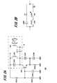
- FIG. 2A is a circuit diagram of the first oscillation circuit 102.
- FIG. 2B is an equivalent circuit of a portion surrounded by a dotted line in the circuit diagram of the first oscillation circuit 102.
- the first oscillation circuit 102 is a well-known base-grounded Colpitts oscillation circuit.
- the base of the transistor 201 which is an NPN transistor, is supplied with a fixed bias current by the resistors R202 and R203 and is grounded in an AC manner by the capacitor C204.
- a capacitor C205 and a coil L206 are connected in parallel between the collector of the transistor 201 and the power supply terminal + B.
- a capacitor C207 is connected between the collector and emitter of the transistor 201.
- a capacitor C208 and a resistor R209 are connected in parallel between the emitter of the transistor 201 and the ground node.
- the helical antenna 103 is connected to the collector of the transistor 201 via a capacitor C210.
- the output signal of the first oscillation circuit 102 is obtained from the collector of the transistor 201 through the capacitor C210.
- Capacitors C205 and C210, a coil L206, and a helical antenna 103 surrounded by a dotted line portion in FIG. 2A can be regarded as an AC equivalent circuit shown in FIG. 2B.
- it includes a resistance component R c is the capacitor C 205.
- the coil L206 and the helical antenna 103 include a resistance component RL .
- the helical antenna 103 is connected in series with the coil L206, and the inductance changes according to the change of the distributed constant. The change of the distribution constant in the helical antenna 103 is caused by the proximity of a human body or the like.
- the Colpitts oscillation circuit shown in FIG. 2A can be understood as a coil in which a helical antenna 103 is connected through a capacitor C210 to a coil constituting a resonance circuit of a known Colpitts oscillation circuit.
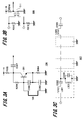
- FIG. 3A is a circuit diagram of the second oscillation circuit 104.
- FIG. 3B is a circuit diagram of the mixer 106.
- FIG. 3C is a circuit diagram of the BPF 107.
- the second oscillation circuit 104 is a well-known Colpitts oscillation circuit. Unlike the Colpitts oscillation circuit of FIG. 2A, capacitors C302 and C303 and a loop antenna 105, that is, a resonance circuit including a coil, are provided between the base and emitter of the transistor 301.
- the loop antenna 105 is connected between the base of the transistor 301 and the ground node. Further, capacitors C302 and C303 are connected in series with the loop antenna 105 in parallel. The connection point between the capacitors C302 and C303 is connected to the emitter of the transistor 301. A resistor R304 is connected between the emitter of the transistor 301 and the ground node. A resistor R305 is connected between the collector of the transistor 301 and the power supply terminal + B. A resistor R306 is connected between the collector and base of the transistor 301. Therefore, the resistor R306 constitutes a well-known self-bias circuit. The output signal of the second oscillation circuit 104 is obtained from the collector of the transistor 301 through the capacitor C307.
- the inductance of the loop antenna 105 changes due to the change of the distribution constant.
- the change of the distribution constant in the loop antenna 105 is caused by the proximity of a human body or the like. That is, the oscillation frequency of the second oscillation circuit 104 changes as the inductance of the loop antenna 105 that forms part of the resonance circuit changes.
- the Colpitts oscillation circuit is used for the first oscillation circuit 102 and the second oscillation circuit 104, the oscillation circuit is not limited to this. Any oscillation circuit using an LC resonance circuit such as a well-known Hartley oscillation circuit may be used.
- the output signal of the first oscillation circuit 102 is applied to the first gate of the dual gate FET 311 connected between the resistor R312 and the ground node.
- the output signal of the second oscillation circuit 104 is applied to the second gate of the dual gate FET 311 connected between the resistor R313 and the ground node. Then, a multiplication output signal is obtained from the drain of the dual gate FET 311 connected to the power supply terminal + B through the resistor R314.
- a typical BPF 107 is provided with a series resonance circuit of a coil L321 and a capacitor C322 as a first stage on a signal line, and between the other end of the capacitor C322 and a ground node, a coil L323 and a capacitor C324 as a second stage are provided.
- a parallel resonant circuit is provided.
- this combination of circuit elements is connected in series as necessary, and the final stage ends with a series resonance circuit (coil L325 and capacitor C326).
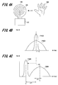
- FIG. 4A is a schematic external view of the proximity sensor 101.
- FIG. 4B shows frequency characteristics of the helical antenna 103 and the loop antenna 105 before the human body approaches.
- FIG. 4C shows the frequency characteristics of the helical antenna 103 and the loop antenna 105 when a human body is in proximity.
- FIG. 5 is a graph showing the relationship between the distance between the proximity sensor 101 and the human body and the frequency of the signal obtained from the mixer 106.
- the circuit configuration of the proximity sensor 101 is simple.
- the proximity sensor 101 can be easily mounted by hand on a substrate approximately 5 cm square. If chip components are used, the proximity sensor 101 can be mounted on a 2.5 cm square substrate. Further, by appropriately selecting the oscillation frequency employed in the first oscillation circuit 102 and the second oscillation circuit 104, the size of the helical antenna 103 and the loop antenna 105 can be reduced.
- a helical antenna 103 is provided on the inner periphery of the loop antenna 105. Further, for example, by mounting these antennas together with the circuit of the proximity sensor 101 on the flexible substrate, it is possible to achieve miniaturization and improve the yield of mass production.
- FIG. 4B shows the frequency characteristic P402 of the helical antenna 103 and the frequency characteristic P403 of the loop antenna 105 before the human body 401 approaches.
- the center frequencies of the helical antenna 103 and the loop antenna 105 coincide with the first oscillation circuit 102 and the second oscillation circuit 104.
- the first oscillation circuit 102 and the second oscillation circuit 104 are designed to resonate at the same frequency. For this reason, in FIG.
- the helical antenna 103 and the loop antenna 105 show the same center frequency.
- the helical antenna 103 has a strong gain in a narrow frequency band as indicated by a curve P402.
- the loop antenna 105 has a low gain in a wide frequency band as indicated by a curve P403.
- FIG. 4C shows frequency characteristics of the helical antenna 103 and the loop antenna 105 after the human body 401 comes close.
- the resonance frequency of the helical antenna 103 decreases as the human body 401 approaches as indicated by the curve P404.
- the oscillation frequency of the first oscillation circuit 102 changes from f1 to f1 ′.
- the resonance frequency of the loop antenna 105 increases as the human body 401 approaches.
- the oscillation frequency of the second oscillation circuit 104 changes from f2 to f2 ′.
- a graph showing the relationship between the distance between the proximity sensor 101 and the human body 401 and the frequency of the frequency difference signal obtained from the mixer 106 is as shown in FIG. If the frequency f1 that is the oscillation frequency of the first oscillation circuit 102 and the frequency f2 that is the oscillation frequency of the second oscillation circuit 104 are set to the same frequency, the frequency difference signal
- ( f2-f1) is zero in principle.
- the frequency f1 of the first oscillation circuit 102 decreases with a large frequency fluctuation
- the frequency difference signal f2-f1 appears as a signal having a predetermined frequency.
- the frequency difference signal f2-f1 reaches a predetermined frequency.
- the graph shown in FIG. 5 is represented by a curve close to a linear function.
- shaft of FIG. 5 is a common logarithm display of a frequency.
- the proximity sensor 101 can obtain an appropriate detection output signal corresponding to the distance of the human body 401 with respect to the proximity sensor 101.
- the passband of the BPF 107 is ⁇ fa, which is a frequency at which the frequency difference signal f2-f1 clearly appears when the human body 401 approaches the predetermined distance from the proximity sensor 101, and when the human body 401 is sufficiently close to the proximity sensor 101. If the frequency difference signal f2-f1 is set to include ⁇ fb, when the frequency difference signal f2-f1 is in the range of ⁇ fa to ⁇ fb, the BPF 107 outputs a significant gain output signal.
- the proximity sensor 101 can appropriately detect the state in which the human body 401 is close to a predetermined distance and output it as the first output signal. Further, the pass band of the BPF 107 is correlated with the distance of the human body 401 with respect to the proximity sensor 101. Therefore, the detection distance of the human body 401 with respect to the proximity sensor 101 can be freely set depending on the setting of the pass band of the BPF 107.
- a prototype of the proximity sensor 101 was manufactured in which the oscillation frequency f1 of the first oscillation circuit 102 and the oscillation frequency f2 of the second oscillation circuit 104 were set to 120 MHz. Then, when the human body 401 comes close to the prototype helical antenna 103 and the loop antenna 105 by about 1 m, the oscillation frequency f1 ′ of the first oscillation circuit 102 decreases to about 119 MHz, and the oscillation frequency f2 ′ of the second oscillation circuit 104 becomes 120. It rose to about 2MHz. For this reason, the frequency difference signal f2'-f1 'appears as a signal having a frequency of about 1 MHz, and the prototype can detect the presence of the human body 401 significantly.
- the frequency of the frequency difference signal f2-f1 is preferably below the detection limit of the BPF 107.
- the frequency of the frequency difference signal f2-f1 is desirably 100 kHz or less, preferably less than 50 kHz.
- the proximity sensor 101 obtains the first output signal from the first output terminal 110 according to the distance between the helical antenna 103 and the loop antenna 105 and the human body 401 through the BPF 107 and the AM detection circuit 108.
- the FM detection circuit 111 outputs a signal corresponding to a change in frequency and phase of the frequency difference signal f2-f1. That is, the FM detection circuit 111 outputs a signal corresponding to the moving speed of the human body 401, not the distance between the helical antenna 103 and the loop antenna 105 and the human body 401.
- this signal is input to the microcomputer 113 including the A / D converter together with the first output signal. Then, while the first output signal indicates logic “true”, the voltage of the signal obtained from the second LPF 112 is compared with a predetermined threshold value. Then, when a human hand is within a predetermined distance range from the helical antenna 103 and the loop antenna 105, a second output signal indicating a determination result corresponding to the moving speed of the hand is obtained from the second output terminal 114. be able to.
- the proximity sensor 101 it is possible to change the operation of the application of the proximity sensor 101 such that a relatively dark room light is turned on when the hand is slowly approached, and a bright room light is turned on when the hand is approached quickly. Since the movement of the human body 401 can be detected from the output signal of the FM detection circuit 111, the output signal of the FM detection circuit 111 is binarized by an LPF and a comparator, and the movement of the human body 401 during sleep is measured. It can be used as a sensor.
- the FM detection circuit 111 when the FM detection circuit 111 outputs a significant output signal, it means that the human body 401 that is the detection target is close. Therefore, the output signal of the FM detection circuit 111 is not treated as an analog voltage, but as a digital logic signal, and a logical product of the first output signal of the AM detection circuit 108 and the output signal of the FM detection circuit 111 is output as a second output. By outputting as a signal, it can be expected to reduce the influence of noise mixed in the first output signal of the AM detection circuit 108 due to reflection of radio waves, external noise, and the like.
- the microcomputer 113 functions as a logic signal output unit (AND gate) that outputs a logical product of the first output signal of the AM detection circuit 108 and the output signal of the FM detection circuit 111.
- the first BPF outputs the frequency difference signal f2-f1 when the distance of the human body 401 from the helical antenna 103 and the loop antenna 105 is in the range of 1 m to 50 cm. Design the amount of attenuation appropriately. Then, the second BPF attenuates at the BPF bandwidth and the stop frequency so as to output the frequency difference signal f2-f1 when the distance of the human body 401 to the helical antenna 103 and the loop antenna 105 is within a range of 30 cm. Design the quantity appropriately.
- the first AM detection circuit 108 is connected after the first BPF, and the second AM detection circuit 108 is connected after the second BPF. Then, different output signals are obtained by the first AM detection circuit 108 and the second AM detection circuit 108 according to the distance of the human body 401 to the helical antenna 103 and the loop antenna 105. Further, when a timer is started based on the signal obtained from the first AM detection circuit 108 and the time difference of the signal obtained from the second AM detection circuit 108 is measured, a procedure similar to the above-described FM detection circuit 111 is performed. It is also possible to obtain a determination result according to the moving speed.
- an LPF that removes the f1 + f2 signal from the output of the mixer 106 is provided, and then the distance of the human body 401 to the helical antenna 103 and the loop antenna 105 is determined using a well-known FFT (Fast Fourier Transform). The presence or absence of a corresponding specific frequency component may be detected.
- FFT Fast Fourier Transform
- the proximity sensor 101 in the above-described embodiment causes the first oscillation circuit 102 and the second oscillation circuit 104 to oscillate at substantially the same frequency, and when the human body 401 approaches the helical antenna 103 and the loop antenna 105, This is a mechanism for detecting the frequency difference signal f2-f1 that appears when each oscillation frequency changes.
- the respective oscillation frequencies change. You may comprise so that the difference in frequency may approximate zero.
- the oscillation frequency of the second oscillation circuit 104 is set lower than the oscillation frequency of the first oscillation circuit 102.
- This frequency difference signal f2-f1 is not shown when the human body 401 comes close to the helical antenna 103 and the loop antenna 105, but instead of the first LPF 109 and at the subsequent stage of the FM detection circuit 111. Is provided with a high-pass filter (HPF) instead of the second LPF 112.
- HPF high-pass filter
- the helical antenna 103 that is, the first oscillation circuit 102 that uses an antenna having an open end as a part of the element of the resonance circuit
- the loop antenna 105 that is, does not have an open end and both ends are in the circuit.
- the proximity sensor 101 has been described in which the second oscillation circuit 104 that uses the connected antenna as a part of the element of the resonance circuit is oscillated at substantially the same frequency.
- the first oscillation circuit 102 connected to the helical antenna 103 is connected to the loop antenna 105, whereas the oscillation frequency decreases.
- the second oscillation circuit 104 having a higher oscillation frequency.
- the change in the oscillation frequency in each oscillation circuit is extracted by the BPF 107 after a frequency difference signal is generated by the mixer 106 (multiplier).
- the frequency of the extracted frequency difference signal increases as the distance of the human body 401 from the helical antenna 103 and the loop antenna 105 decreases.
- this signal is extracted by the BPF 107, it is used for proximity detection through envelope detection.
- a signal corresponding to the distance of the human body 401 from the helical antenna 103 and the loop antenna 105 can be obtained.
- the proximity sensor 101 of the present embodiment has a signal frequency as low as about several tens to several hundreds of MHz compared to the conventional Doppler sensor. For this reason, the price of a circuit element is low, for example, an inexpensive small signal transistor can be used. In addition, since the frequency of the signal to be handled is low, it is easy to mount a circuit including the BPF 107. Furthermore, the proximity sensor 101 of the present embodiment has an extremely small circuit scale as compared with a conventional Doppler sensor. As is well known, the AM detection circuit 108 may be a single diode.
- the semiconductor elements excluding the diodes necessary for mounting the proximity sensor 101 of this embodiment are one transistor 201 in the first oscillation circuit 102 and one transistor 301 in the second oscillation circuit 104.
- One dual gate FET 311 is required for the mixer 106, which is a total of three. Therefore, it can be manufactured at low cost and mass production is easy.
- the proximity sensor 101 of the present embodiment is not used for irradiating a measurement object with radio waves.
- the proximity sensor 101 of this embodiment only detects changes in the antenna distribution constant. That is, both the first oscillation circuit 102 and the second oscillation circuit 104 do not require power for emitting radio waves. Therefore, the power consumption is extremely small as compared with the conventional Doppler sensor. Also in this respect, the proximity sensor 101 of this embodiment can use an inexpensive semiconductor element. Further, since the frequency difference signal of the two oscillation circuits is detected, the frequency drift based on the change of the circuit constant accompanying the temperature change is canceled when it passes through the mixer 106. Therefore, in principle, there is very little temperature fluctuation, so it is resistant to temperature fluctuation, robust, easy to handle, and has a wide range of applications.
- Each of the above-described configurations, functions, processing units, and the like may be realized by hardware by designing a part or all of them with, for example, an integrated circuit. Further, each of the above-described configurations, functions, and the like may be realized by software for interpreting and executing a program that realizes each function by the processor. Information such as programs, tables, and files that realize each function should be held in memory, hard disk, volatile or non-volatile storage such as SSD (Solid State Drive), or recording media such as IC cards and optical disks. Can do.
- the control lines and information lines are those that are considered necessary for the explanation, and not all the control lines and information lines on the product are necessarily shown. Actually, it may be considered that almost all the components are connected to each other.
Landscapes
- Life Sciences & Earth Sciences (AREA)
- Engineering & Computer Science (AREA)
- Physics & Mathematics (AREA)
- Remote Sensing (AREA)
- Geology (AREA)
- Environmental & Geological Engineering (AREA)
- Electromagnetism (AREA)
- General Life Sciences & Earth Sciences (AREA)
- General Physics & Mathematics (AREA)
- Geophysics (AREA)
- Electronic Switches (AREA)
- Geophysics And Detection Of Objects (AREA)
- Radar Systems Or Details Thereof (AREA)
Abstract
Description
赤外線等の光を用いる人感センサは、受光素子が人体から発される熱赤外線や、あるいは赤外線発光ダイオードから赤外線を人体に照射し、その反射光を受光するために所定の「窓」を必要とする。
一方、近年スマートフォン等に広く用いられている、静電容量の変化を検出する人感センサは、検出距離が極めて短い。
特許文献1に開示されるセンサは、電波を用いたセンサの一種であり、ドップラーセンサと呼ばれるものである。ドップラーセンサはその名称の通り、ドップラー効果を利用して対象物の存在等を検出するセンサである。
上記した以外の課題、構成及び効果は、以下の実施形態の説明により明らかにされる。
図1は、本発明の実施形態に係る、近接センサ101のブロック図である。
本発明の実施形態に係る近接センサ101は、ヘリカルアンテナ103を有する第一発振回路102と、ループアンテナ105を有する第二発振回路と、ミキサ106以降の信号処理回路に分けることができる。
ミキサ106、BPF107、そしてAM検波回路108は、第一発振回路102から出力される第一の周波数f1の信号と、第二発振回路104から出力される第二の周波数f2の信号に基づいて、任意の検出対象の近接状態を検出する近接検出部と考えることができる。
第二発振回路104は、第二の周波数f2の信号を発振して、ループアンテナ105から第二の周波数f2の電波を発する。なお、第二発振回路104は、ループアンテナ105の分布定数の変化に追従して発振周波数が変わる、共振回路でもある。
ミキサ106の出力信号はバンドパスフィルタ(以下「BPF」と略)107に入力される。BPF107は、f1±f2の信号から|f1-f2|の信号を取り出す。
BPF107から出力される、特定の周波数範囲の信号は、例えば周知のダイオードよりなるAM検波回路108によって包絡線検波が行われる。そして、ローパスフィルタ(以下「LPF」と略)である第一LPF109を通じてノイズ成分が除去され、第一出力端子110から第一出力信号が出力される。
以上が、本発明の実施形態に係る、近接センサ101の基本構成である。なお、FM検波回路111、第二LPF112、マイコン113及び第二出力端子114の構成及び動作説明は後述する。
図2Aは、第一発振回路102の回路図である。図2Bは、第一発振回路102の回路図中、点線で囲んだ部分の等価回路である。
第一発振回路102は、周知のベース接地型コルピッツ発振回路である。
NPNトランジスタであるトランジスタ201のベースは、抵抗R202とR203によって固定バイアス電流が供給されると共に、コンデンサC204によって交流的に接地されている。
トランジスタ201のコレクタと電源端子+Bとの間には、コンデンサC205とコイルL206が並列接続されている。
トランジスタ201のコレクタとエミッタとの間には、コンデンサC207が接続されている。
トランジスタ201のエミッタと接地ノードとの間には、コンデンサC208と抵抗R209が並列接続されている。
トランジスタ201のコレクタには、コンデンサC210を介してヘリカルアンテナ103が接続されている。
第一発振回路102の出力信号は、トランジスタ201のコレクタからコンデンサC210を通じて得られる。
図2B中、コンデンサC205には抵抗成分Rcが含まれている。また、コイルL206とヘリカルアンテナ103には抵抗成分RLが含まれている。
ヘリカルアンテナ103はコイルL206と直列接続され、分布定数の変化によってインダクタンスが変化する。ヘリカルアンテナ103における分布定数の変化は、人体等が近接することによって引き起こされる。すなわち、共振回路の一部をなすコイルL206とヘリカルアンテナ103のうち、ヘリカルアンテナ103のインダクタンスが変化することで、第一発振回路102の発振周波数は変化する。
図2Aに示すコルピッツ発振回路は、周知のコルピッツ発振回路の共振回路を構成するコイルに、コンデンサC210を通じてヘリカルアンテナ103を接続したものと解することができる。
図3Aは、第二発振回路104の回路図である。図3Bは、ミキサ106の回路図である。図3Cは、BPF107の回路図である。
先ず、図3Aを参照して、第二発振回路104の構成を説明する。
第二発振回路104は、周知のコルピッツ発振回路である。図2Aのコルピッツ発振回路とは異なり、トランジスタ301のベース-エミッタ間にコンデンサC302とC303とループアンテナ105、すなわちコイルによる共振回路が設けられている。
ループアンテナ105はトランジスタ301のベースと接地ノードとの間に接続されている。また、ループアンテナ105と並列に、コンデンサC302とC303が直列接続されている。そして、コンデンサC302とC303の接続点はトランジスタ301のエミッタに接続されている。トランジスタ301のエミッタと接地ノードとの間には、抵抗R304が接続されている。
トランジスタ301のコレクタと電源端子+Bとの間には、抵抗R305が接続されている。また、トランジスタ301のコレクタ-ベース間には抵抗R306が接続されており、したがって抵抗R306は周知の自己バイアス回路を構成する。
第二発振回路104の出力信号は、トランジスタ301のコレクタからコンデンサC307を通じて得られる。
なお、第一発振回路102及び第二発振回路104はコルピッツ発振回路を用いたが、発振回路はこれに限られない。周知のハートレー発振回路等、LC共振回路を用いる発振回路であればよい。
ミキサ106は多種多様な実施態様が考えられるが、高周波において容易に実現できるものは、図3Bに示すデュアルゲートFET311である。
抵抗R312が接地ノードとの間に接続されているデュアルゲートFET311の第一ゲートには、第一発振回路102の出力信号が印加される。
抵抗R313が接地ノードとの間に接続されているデュアルゲートFET311の第二ゲートには、第二発振回路104の出力信号が印加される。
すると、抵抗R314を通じて電源端子+Bに接続されているデュアルゲートFET311のドレインから乗算出力信号が得られる。
典型的なBPF107は、信号線路に一段目となるコイルL321とコンデンサC322の直列共振回路が設けられ、コンデンサC322の他端と接地ノードとの間には二段目となるコイルL323とコンデンサC324の並列共振回路が設けられる。以下、この回路素子の組み合わせが必要に応じて直列接続され、最後の段は直列共振回路(コイルL325及びコンデンサC326)で終わる。
図4Aは、近接センサ101の概略的外観図である。
図4Bは、人体が近接する前の、ヘリカルアンテナ103及びループアンテナ105の周波数特性である。
図4Cは、人体が近接した時の、ヘリカルアンテナ103及びループアンテナ105の周波数特性である。
図5は、近接センサ101と人体との距離と、ミキサ106から得られる信号の周波数との関係を示すグラフである。
図1から図3C迄の説明によって、近接センサ101の回路構成は簡素なものであることが判る。近接センサ101は、およそ5cm四方の基板上に、手作業でも容易に実装できる。チップ部品を使用すれば、近接センサ101は2.5cm四方の基板上でも実装可能である。また、第一発振回路102及び第二発振回路104にて採用する発振周波数を適切に選択することで、ヘリカルアンテナ103とループアンテナ105の大きさも小さくすることができる。
図4Bは、人体401が近接する前の、ヘリカルアンテナ103の周波数特性P402と、ループアンテナ105の周波数特性P403を示す。なお、説明を簡単にするために、ヘリカルアンテナ103とループアンテナ105の中心周波数と、第一発振回路102と第二発振回路104が一致しているものと仮定する。
本発明の実施形態に係る近接センサ101において、第一発振回路102と第二発振回路104は同じ周波数で共振するように設計されている。このため、図4Bではヘリカルアンテナ103とループアンテナ105が同じ中心周波数を示している。図4B中、ヘリカルアンテナ103は曲線P402に示されるように、狭い周波数帯域で強いゲインを持つ。一方、ループアンテナ105は曲線P403に示されるように、広い周波数帯域で低いゲインを持つ。
図4C中、ヘリカルアンテナ103は曲線P404に示されるように、人体401が近接すると共振周波数が低くなる。このため、第一発振回路102の発振周波数はf1からf1’に変化する。この時の周波数移動幅Δf1(=f1-f1’)は比較的大きい。
これに対し、ループアンテナ105は曲線P405に示されるように、人体401が近接すると共振周波数が高くなる。このため、第二発振回路104の発振周波数はf2からf2’に変化する。この時の周波数移動幅Δf2(=f2’-f2)はΔf1と比べると小さい。
一方、誘電体がヘリカルアンテナ等、開放端を有するアンテナに近づくと、アンテナを取り巻く空間のキャパシタンスが上がる。キャパシタンスが上がれば、開放端を有するアンテナの共振周波数は低くなる。開放端を有するアンテナと誘電体との距離に対する共振周波数の変化については、「アンテナ装置」WO2010/47032号公報にも記載されている。
第一発振回路102の発振周波数である周波数f1及び第二発振回路104の発振周波数である周波数f2を同じ周波数に設定しておくと、ミキサ106から得られる信号のうち、周波数差信号|f1-f2|(=f2-f1)は、原理的にはゼロとなる。そして、人体401が近接センサ101に近接することによって、第一発振回路102の周波数f1は大きな周波数変動を伴って低くなり、第二発振回路104の周波数f2は小さな周波数変動を伴って高くなる。すなわち、周波数差信号f2-f1が所定の周波数の信号となって表れる。最終的に、近接センサ101のヘリカルアンテナ103及びループアンテナ105と人体401との距離がゼロになると、周波数差信号f2-f1は所定の周波数に至る。このため、図5に示すグラフは一次関数に近い曲線で表される。
なお、図5の縦軸は周波数の常用対数表示である。
BPF107の通過帯域を、人体401が近接センサ101に対し、所定の距離に近づくことによって周波数差信号f2-f1が明確に現れる周波数であるΔfaと、人体401が十分近接センサ101に近接した場合の周波数差信号f2-f1の周波数であるΔfbを含むように設定すると、周波数差信号f2-f1がΔfaからΔfbの範囲にある時、BPF107は有意なゲインの出力信号を出力する。この、BPF107の出力信号をAM検波回路108でAM検波して、ノイズ成分をLPFで除去すると、人体401が近接した状態を示す論理信号として利用可能な信号が得られる。したがって、近接センサ101は人体401が所定の距離に近接した状態を適切に検出し、第一出力信号として出力できる。
更に、BPF107の通過帯域は、近接センサ101に対する人体401の距離と相関性がある。したがって、BPF107の通過帯域の設定次第で、近接センサ101に対する人体401の検出距離を自由に設定できる。
好ましくは、人体401がアンテナに近接していない時、周波数差信号f2-f1の周波数はBPF107の検出限界以下であることが好ましい。例えば、BPF107の低周波側カットオフ周波数が1MHzである場合、周波数差信号f2-f1の周波数は100kHz以下、好ましくは50kHzを下回ることが望ましい。
以上、本発明の実施形態に係る近接センサ101は、BPF107とAM検波回路108を通じて、ヘリカルアンテナ103及びループアンテナ105と人体401との距離に応じた第一出力信号を第一出力端子110から得られることを説明した。
一方、FM検波回路111は、周波数差信号f2-f1の周波数及び位相の変化に応じた信号を出力する。つまり、FM検波回路111はヘリカルアンテナ103及びループアンテナ105と人体401との距離ではなく、人体401の移動速度に応じた信号を出力する。この信号を、第二LPF112でノイズ成分を除去した後、第一出力信号と共にA/D変換器を内蔵するマイコン113に入力する。そして、第一出力信号が論理の「真」を示している間に、第二LPF112から得られる信号の電圧を、所定の閾値と比較する。すると、人の手がヘリカルアンテナ103及びループアンテナ105に対して所定の距離の範囲にある時の、手の移動速度に応じた判定結果を示す第二出力信号を、第二出力端子114から得ることができる。
例えば、手をゆっくり近づけたら比較的暗いルームライトを点灯させ、手を早く近づけたら明るいルームライトを点灯させる、というように、近接センサ101のアプリケーションの動作に変化を持たせることが可能になる。また、FM検波回路111の出力信号から人体401の動きを検出できるので、FM検波回路111の出力信号をLPFとコンパレータで二値化して、睡眠時の人体401の動きを計測する、睡眠計のセンサとしての利用が可能である。
(1)上述の実施形態では、BPF107は一つだけだったが、BPF107を二つ以上設けることも考えられる。
例えば、第一のBPFは、ヘリカルアンテナ103及びループアンテナ105に対する人体401の距離が1mから50cmの範囲にある時に、周波数差信号f2-f1を出力するように、BPFの帯域幅と阻止周波数における減衰量を適切に設計する。
そして、第二のBPFは、ヘリカルアンテナ103及びループアンテナ105に対する人体401の距離が30cm以内の範囲にある時に、周波数差信号f2-f1を出力するように、BPFの帯域幅と阻止周波数における減衰量を適切に設計する。
更に、第一のAM検波回路108から得られる信号に基いてタイマを起動して、第二のAM検波回路108から得られる信号の時間差を計測すると、前述のFM検波回路111と類似する、手の移動速度に応じた判定結果を得ることもできる。
これに対し、逆に予め第一発振回路102と第二発振回路104とを異なる周波数で発振させ、ヘリカルアンテナ103とループアンテナ105に人体401が近接すると、それぞれの発振周波数が変化することによって、周波数の差がゼロに近似するように構成してもよい。具体的には、第二発振回路104の発振周波数を、第一発振回路102の発振周波数に対して低めに設定する。人体近接時にはそれぞれの発振周波数の差が小さくなる。この周波数差信号f2-f1が、ヘリカルアンテナ103とループアンテナ105に人体401が近接した時に現れなくなるように、AM検波回路108の後段には第一LPF109の代わりに、またFM検波回路111の後段には第二LPF112の代わりに、ハイパスフィルタ(HPF)を設ける。
このような近接センサ101において、ヘリカルアンテナ103とループアンテナ105に人体401が近接すると、ヘリカルアンテナ103に接続される第一発振回路102は発振周波数が低くなるのに対し、ループアンテナ105に接続される第二発振回路104は発振周波数が高くなる。この、各々の発振回路における発振周波数の変化を、ミキサ106(乗算器)で周波数差信号を生成した後、BPF107で抽出する。抽出された周波数差信号の周波数は、ヘリカルアンテナ103及びループアンテナ105に対する人体401の距離が近づくに連れて高くなる。この信号を、BPF107で抽出した後、包絡線検波を通して、近接の検出に用いる。BPF107の中心周波数及び帯域幅を適切に設定することで、ヘリカルアンテナ103とループアンテナ105に対する人体401の距離に応じた信号を得ることができる。
更に、本実施形態の近接センサ101は、従来のドップラーセンサに比べて、回路規模が極めて小さい。周知のように、AM検波回路108はダイオード一個で済む。第一出力信号だけを取り出す場合、本実施形態の近接センサ101を実装するために必要な、ダイオードを除く半導体素子は、第一発振回路102にトランジスタ201一個、第二発振回路104にトランジスタ301一個、ミキサ106にデュアルゲートFET311一個の、合計三個で済む。したがって、安価に製造できると共に、量産も容易である。
更に、二つの発振回路の周波数差信号を検出するので、温度変化に伴う回路定数の変化に基づく周波数ドリフトは、ミキサ106を通過した時点で打ち消される。したがって、原理的に温度変動が極めて少ないので温度変動に強く、堅牢で、扱い易く、適用範囲が広い。
例えば、上記した実施形態は本発明をわかりやすく説明するために装置及びシステムの構成を詳細且つ具体的に説明したものであり、必ずしも説明した全ての構成を備えるものに限定されるものではない。また、ある実施形態の構成の一部を他の実施形態の構成に置き換えることは可能であり、更にはある実施形態の構成に他の実施形態の構成を加えることも可能である。また、各実施形態の構成の一部について、他の構成の追加・削除・置換をすることも可能である。
また、上記の各構成、機能、処理部等は、それらの一部又は全部を、例えば集積回路で設計するなどによりハードウェアで実現してもよい。また、上記の各構成、機能等は、プロセッサがそれぞれの機能を実現するプログラムを解釈し、実行するためのソフトウェアで実現してもよい。各機能を実現するプログラム、テーブル、ファイル等の情報は、メモリや、ハードディスク、SSD(Solid State Drive)等の揮発性あるいは不揮発性のストレージ、または、ICカード、光ディスク等の記録媒体に保持することができる。
また、制御線や情報線は説明上必要と考えられるものを示しており、製品上必ずしもすべての制御線や情報線を示しているとは限らない。実際には殆ど全ての構成が相互に接続されていると考えてもよい。
Claims (7)
- 開放端を有する第一のアンテナを共振回路の素子の一部として用いる第一発振回路と、
両端が回路に接続される第二のアンテナを共振回路の素子の一部として用いる第二発振回路と、
前記第一発振回路が出力する第一の出力信号と、前記第二発振回路が出力する第二の出力信号の周波数差に基いて任意の検出対象の近接状態を検出する近接検出部と
を具備する近接センサ。 - 前記近接検出部は、
前記第一の出力信号及び前記第二の出力信号を受けて、周波数差信号を生成するミキサと、
前記周波数差信号から特定の周波数の信号を通過させるバンドパスフィルタと、
前記バンドパスフィルタの出力信号に包絡線検波を施すAM検波回路と
を有する、請求項1に記載の近接センサ。 - 前記第一発振回路と、前記第二発振回路は、前記任意の検出対象が近接していない状態において、前記第一の出力信号と前記第二の出力信号の周波数差が前記バンドパスフィルタの低周波側カットオフ周波数以下である、
請求項2に記載の近接センサ。 - 前記バンドパスフィルタを通過する前記周波数差信号の周波数は、前記任意の検出対象が前記第一のアンテナ及び前記第二のアンテナに所定の距離にて近接した状態における周波数である、
請求項3に記載の近接センサ。 - 更に、
前記バンドパスフィルタの出力信号に周波数及び/又は位相差検波を施すFM検波回路と、
前記AM検波回路の出力信号と前記FM検波回路の出力信号の論理積を出力する論理信号出力部と
を有する、請求項2又は3又は4に記載の近接センサ。 - 前記第一発振回路と、前記第二発振回路は、前記任意の検出対象が近接している状態において、前記第一の出力信号と前記第二の出力信号の周波数差が前記バンドパスフィルタの低周波側カットオフ周波数以下である、請求項2に記載の近接センサ。
- 前記バンドパスフィルタを通過する前記周波数差信号の周波数は、前記任意の検出対象が前記第一のアンテナ及び前記第二のアンテナに所定の距離にて近接した状態における周波数である、
請求項6に記載の近接センサ。
Priority Applications (4)
| Application Number | Priority Date | Filing Date | Title |
|---|---|---|---|
| CN201480051664.9A CN105556846A (zh) | 2013-09-19 | 2014-09-10 | 接近传感器 |
| JP2015537876A JP6308631B2 (ja) | 2013-09-19 | 2014-09-10 | 近接センサ |
| DE112014004314.1T DE112014004314T5 (de) | 2013-09-19 | 2014-09-10 | Annäherungssensor |
| US15/023,051 US9971056B2 (en) | 2013-09-19 | 2014-09-10 | Proximity sensor |
Applications Claiming Priority (2)
| Application Number | Priority Date | Filing Date | Title |
|---|---|---|---|
| JP2013-194081 | 2013-09-19 | ||
| JP2013194081 | 2013-09-19 |
Publications (1)
| Publication Number | Publication Date |
|---|---|
| WO2015041121A1 true WO2015041121A1 (ja) | 2015-03-26 |
Family
ID=52688771
Family Applications (1)
| Application Number | Title | Priority Date | Filing Date |
|---|---|---|---|
| PCT/JP2014/073990 Ceased WO2015041121A1 (ja) | 2013-09-19 | 2014-09-10 | 近接センサ |
Country Status (5)
| Country | Link |
|---|---|
| US (1) | US9971056B2 (ja) |
| JP (1) | JP6308631B2 (ja) |
| CN (1) | CN105556846A (ja) |
| DE (1) | DE112014004314T5 (ja) |
| WO (1) | WO2015041121A1 (ja) |
Families Citing this family (6)
| Publication number | Priority date | Publication date | Assignee | Title |
|---|---|---|---|---|
| JP6734526B2 (ja) * | 2016-06-07 | 2020-08-05 | 東京パーツ工業株式会社 | 静電容量式近接センサおよびこの静電容量式近接センサを備えるドアハンドル装置 |
| JP6968545B2 (ja) * | 2017-02-01 | 2021-11-17 | オムロン株式会社 | 近接センサ |
| KR20190045579A (ko) * | 2017-10-24 | 2019-05-03 | 삼성전기주식회사 | 카메라 모듈의 액츄에이터 |
| WO2020150463A1 (en) * | 2019-01-16 | 2020-07-23 | Wiliot Ltd. | Local oscillator frequency-based proximity sensor |
| DE102019103670B4 (de) * | 2019-02-13 | 2024-07-25 | Balluff Gmbh | Induktiver Sensor und Verfahren zu seinem Betrieb |
| CN111337986A (zh) * | 2020-05-18 | 2020-06-26 | 上海索迪龙自动化有限公司 | 传感器装置以及检测系统 |
Citations (2)
| Publication number | Priority date | Publication date | Assignee | Title |
|---|---|---|---|---|
| JPH1117515A (ja) * | 1997-06-27 | 1999-01-22 | Omron Corp | 近接センサ |
| JP2003315295A (ja) * | 2002-04-22 | 2003-11-06 | Matsushita Electric Works Ltd | 水分量センサ |
Family Cites Families (20)
| Publication number | Priority date | Publication date | Assignee | Title |
|---|---|---|---|---|
| US4652864A (en) * | 1982-07-26 | 1987-03-24 | Calvin Noel M | Microwave proximity sensor |
| JPH11182109A (ja) * | 1997-12-25 | 1999-07-06 | Aisin Seiki Co Ltd | 物体検知センサおよびそれを用いたドアロック制御装置 |
| SE520154C2 (sv) * | 1999-04-19 | 2003-06-03 | Jokab Safety Ab | Närhetsbrytare, mål, system av sådana närhetsbrytare och mål samt metod för att bestämma ett måls närvaro medelst en närhetsbrytare |
| JP3409752B2 (ja) * | 1999-10-26 | 2003-05-26 | トヨタ自動車株式会社 | 移動物体検知装置、異常警報装置および積載室開放制御装置 |
| US7298314B2 (en) * | 2002-08-19 | 2007-11-20 | Q-Track Corporation | Near field electromagnetic positioning system and method |
| JP3735721B2 (ja) | 2003-02-26 | 2006-01-18 | 防衛庁技術研究本部長 | 電波近接センサ |
| JP4049081B2 (ja) | 2003-10-30 | 2008-02-20 | アイシン精機株式会社 | 近接センサ |
| JP4049075B2 (ja) * | 2003-10-17 | 2008-02-20 | アイシン精機株式会社 | 近接センサ |
| JP4324012B2 (ja) * | 2004-05-20 | 2009-09-02 | 日立オムロンターミナルソリューションズ株式会社 | 変位検知装置および変位検知方法 |
| JP2006162374A (ja) * | 2004-12-06 | 2006-06-22 | Aisin Seiki Co Ltd | 静電容量式物体検知センサ及び物体検知方法 |
| EP1850267B1 (en) * | 2006-04-28 | 2011-11-30 | Semiconductor Energy Laboratory Co., Ltd. | Semiconductor device and position detecting method using the semiconductor device |
| JP5052079B2 (ja) * | 2006-09-08 | 2012-10-17 | 株式会社半導体エネルギー研究所 | センサ装置及びそれを有する容器類 |
| JP5120788B2 (ja) * | 2008-10-16 | 2013-01-16 | Toto株式会社 | 電波センサ |
| JP2012122726A (ja) * | 2009-04-01 | 2012-06-28 | Citizen Holdings Co Ltd | 近接センサ |
| JP4816764B2 (ja) * | 2009-05-28 | 2011-11-16 | カシオ計算機株式会社 | 電波受信装置 |
| JP2011017515A (ja) * | 2009-07-10 | 2011-01-27 | Daikin Industries Ltd | 空調システム |
| JP2011250156A (ja) * | 2010-05-27 | 2011-12-08 | Jvc Kenwood Corp | 受信システム |
| WO2012066838A1 (ja) * | 2010-11-18 | 2012-05-24 | 株式会社村田製作所 | アンテナ装置 |
| JP2014007629A (ja) * | 2012-06-26 | 2014-01-16 | Kyushu Institute Of Technology | 近接センサ |
| US9804712B2 (en) * | 2013-08-23 | 2017-10-31 | Blackberry Limited | Contact-free interaction with an electronic device |
-
2014
- 2014-09-10 CN CN201480051664.9A patent/CN105556846A/zh active Pending
- 2014-09-10 DE DE112014004314.1T patent/DE112014004314T5/de not_active Withdrawn
- 2014-09-10 JP JP2015537876A patent/JP6308631B2/ja not_active Expired - Fee Related
- 2014-09-10 US US15/023,051 patent/US9971056B2/en not_active Expired - Fee Related
- 2014-09-10 WO PCT/JP2014/073990 patent/WO2015041121A1/ja not_active Ceased
Patent Citations (2)
| Publication number | Priority date | Publication date | Assignee | Title |
|---|---|---|---|---|
| JPH1117515A (ja) * | 1997-06-27 | 1999-01-22 | Omron Corp | 近接センサ |
| JP2003315295A (ja) * | 2002-04-22 | 2003-11-06 | Matsushita Electric Works Ltd | 水分量センサ |
Also Published As
| Publication number | Publication date |
|---|---|
| JP6308631B2 (ja) | 2018-04-11 |
| DE112014004314T5 (de) | 2016-07-07 |
| US20160238732A1 (en) | 2016-08-18 |
| US9971056B2 (en) | 2018-05-15 |
| CN105556846A (zh) | 2016-05-04 |
| JPWO2015041121A1 (ja) | 2017-03-02 |
Similar Documents
| Publication | Publication Date | Title |
|---|---|---|
| JP6308631B2 (ja) | 近接センサ | |
| EP0998659B1 (en) | Position and movement resonant sensor | |
| US10955262B2 (en) | Rotation angle sensor for a stator | |
| TW201535219A (zh) | 射頻波透明之電容感測墊 | |
| JP6400018B2 (ja) | 振動センサ及び脈拍センサ | |
| JP2011058836A (ja) | 無線センサ装置 | |
| US11143681B2 (en) | Method and device for determining a sensor coil inductance | |
| US9151862B2 (en) | Buried object detector | |
| KR20150086886A (ko) | 채널 선택도가 개선된 초재생 수신기 및 초재생 수신 방법 | |
| US10058304B2 (en) | Biological signal detection device | |
| JP7029040B2 (ja) | シールドされたケーブルを介して共振器コンデンサに結合されるセンサインダクタを備えるセンサ共振器を用いる遠隔検知 | |
| US9979372B2 (en) | Reconfigurable microwave filters | |
| JP2014007629A (ja) | 近接センサ | |
| JP6498004B2 (ja) | 生体信号センサ | |
| JP6401639B2 (ja) | 生体信号センサ | |
| JP4699097B2 (ja) | 発振装置とこれを用いた送信モジュール | |
| JP2017227460A (ja) | 不要放射抑制装置、及び、不要放射抑制方法 | |
| US11815537B2 (en) | Inductive sensor and method for the operation thereof | |
| CN117990720A (zh) | 测量移动的幅材的设备和方法 | |
| KR20140104678A (ko) | 위치 지시기 및 위치 지시기의 소자 트리밍 방법 | |
| NZ605489A (en) | A buried object detector |
Legal Events
| Date | Code | Title | Description |
|---|---|---|---|
| WWE | Wipo information: entry into national phase |
Ref document number: 201480051664.9 Country of ref document: CN |
|
| 121 | Ep: the epo has been informed by wipo that ep was designated in this application |
Ref document number: 14846195 Country of ref document: EP Kind code of ref document: A1 |
|
| ENP | Entry into the national phase |
Ref document number: 2015537876 Country of ref document: JP Kind code of ref document: A |
|
| WWE | Wipo information: entry into national phase |
Ref document number: 15023051 Country of ref document: US |
|
| WWE | Wipo information: entry into national phase |
Ref document number: 1120140043141 Country of ref document: DE Ref document number: 112014004314 Country of ref document: DE |
|
| 122 | Ep: pct application non-entry in european phase |
Ref document number: 14846195 Country of ref document: EP Kind code of ref document: A1 |