WO2015040945A1 - 信号レベル検知装置および信号レベル検知方法 - Google Patents
信号レベル検知装置および信号レベル検知方法 Download PDFInfo
- Publication number
- WO2015040945A1 WO2015040945A1 PCT/JP2014/068869 JP2014068869W WO2015040945A1 WO 2015040945 A1 WO2015040945 A1 WO 2015040945A1 JP 2014068869 W JP2014068869 W JP 2014068869W WO 2015040945 A1 WO2015040945 A1 WO 2015040945A1
- Authority
- WO
- WIPO (PCT)
- Prior art keywords
- signal
- signal level
- level
- detection device
- level calculation
- Prior art date
- Legal status (The legal status is an assumption and is not a legal conclusion. Google has not performed a legal analysis and makes no representation as to the accuracy of the status listed.)
- Ceased
Links
Images




Classifications
-
- B—PERFORMING OPERATIONS; TRANSPORTING
- B60—VEHICLES IN GENERAL
- B60G—VEHICLE SUSPENSION ARRANGEMENTS
- B60G17/00—Resilient suspensions having means for adjusting the spring or vibration-damper characteristics, for regulating the distance between a supporting surface and a sprung part of vehicle or for locking suspension during use to meet varying vehicular or surface conditions, e.g. due to speed or load
- B60G17/015—Resilient suspensions having means for adjusting the spring or vibration-damper characteristics, for regulating the distance between a supporting surface and a sprung part of vehicle or for locking suspension during use to meet varying vehicular or surface conditions, e.g. due to speed or load the regulating means comprising electric or electronic elements
- B60G17/018—Resilient suspensions having means for adjusting the spring or vibration-damper characteristics, for regulating the distance between a supporting surface and a sprung part of vehicle or for locking suspension during use to meet varying vehicular or surface conditions, e.g. due to speed or load the regulating means comprising electric or electronic elements characterised by the use of a specific signal treatment or control method
-
- B—PERFORMING OPERATIONS; TRANSPORTING
- B60—VEHICLES IN GENERAL
- B60G—VEHICLE SUSPENSION ARRANGEMENTS
- B60G17/00—Resilient suspensions having means for adjusting the spring or vibration-damper characteristics, for regulating the distance between a supporting surface and a sprung part of vehicle or for locking suspension during use to meet varying vehicular or surface conditions, e.g. due to speed or load
- B60G17/06—Characteristics of dampers, e.g. mechanical dampers
-
- F—MECHANICAL ENGINEERING; LIGHTING; HEATING; WEAPONS; BLASTING
- F16—ENGINEERING ELEMENTS AND UNITS; GENERAL MEASURES FOR PRODUCING AND MAINTAINING EFFECTIVE FUNCTIONING OF MACHINES OR INSTALLATIONS; THERMAL INSULATION IN GENERAL
- F16F—SPRINGS; SHOCK-ABSORBERS; MEANS FOR DAMPING VIBRATION
- F16F15/00—Suppression of vibrations in systems; Means or arrangements for avoiding or reducing out-of-balance forces, e.g. due to motion
- F16F15/02—Suppression of vibrations of non-rotating, e.g. reciprocating systems; Suppression of vibrations of rotating systems by use of members not moving with the rotating systems
-
- G—PHYSICS
- G01—MEASURING; TESTING
- G01H—MEASUREMENT OF MECHANICAL VIBRATIONS OR ULTRASONIC, SONIC OR INFRASONIC WAVES
- G01H1/00—Measuring characteristics of vibrations in solids by using direct conduction to the detector
Definitions
- the present invention relates to a signal level detection device and a signal level detection method.
- control is performed to suppress not only the vibration of the sprung member of the vehicle but also the vibration of the unsprung member.
- the unsprung acceleration is detected, the unsprung speed is calculated from the unsprung acceleration, and the thrust for suppressing the vibration of the unsprung member is obtained by multiplying the unsprung speed by the skyhook gain.
- the thrust for suppressing the vibration of the sprung member obtained in the same manner as the above skyhook control is added to the thrust to obtain the thrust to be output to the actuator, and the actuator is subjected to the sprung vibration and unsprung vibration.
- the suppressing thrust is exhibited (see JP2011-84164A).
- the control whether to suppress the vibration of the sprung member or to suppress the vibration of the unsprung member, the control depends on the speed of the sprung member or the speed of the unsprung member, that is, only the speed.
- the control is focused and there is no consideration for the magnitude of vibration. For this reason, vibration suppression may not be performed effectively.
- JP2011-22050A obtains an unsprung speed and a signal having a phase difference of 90 degrees from the unsprung speed filtered with respect to the unsprung speed.
- a technique is disclosed in which the square root of the value obtained by squaring each of the values obtained as a square is obtained as a sequential envelope waveform, and the damping force of the damper is controlled based on the envelope waveform.
- the envelope waveform obtained by processing the signal in this way corresponds to the signal level that is the magnitude of the signal.
- the signal level obtained by processing the signal in this way corresponds to the magnitude of the vibration of the sprung member in the control of the damping force of the damper, and is useful as information effective for vibration suppression.
- the signal level can be obtained by obtaining an envelope waveform.
- the frequency of the signal changes when the vibration frequency changes. For this reason, it is difficult to obtain a signal level with high accuracy with respect to an input of a signal whose frequency changes, and it is difficult to use the control for a control with a wide control frequency band.
- An object of the present invention is to detect a signal level suitable for control with a wide frequency band.
- a signal level detection device that detects a signal level that is the magnitude of a signal, and that generates a plurality of level calculation signals having different phases using an input original signal
- a signal level detection device comprising: a generation unit; and a signal level calculation unit that obtains the signal level based on the original signal and two or more level calculation signals, or three or more level calculation signals.
- a signal level detection method for detecting a signal level which is a signal magnitude, wherein a signal generation step of generating a plurality of level calculation signals having different phases from an original signal, There is provided a signal level detection method including an original signal and the plurality of level calculation signals, or a level calculation step for obtaining the signal level based on the plurality of level calculation signals.
- FIG. 1 is a configuration diagram of a signal level detection apparatus according to an embodiment of the present invention.
- FIG. 2 is a diagram for explaining an object system.
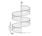
- FIG. 3 is a diagram illustrating a waveform of the level calculation signal.
- FIG. 4 is a diagram illustrating the frequency phase characteristics of the level calculation signal.
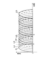
- FIG. 5 is a diagram illustrating a waveform of an absolute value of the level calculation signal.
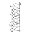
- FIG. 6 is a diagram illustrating a waveform of an absolute value of a level calculation signal with respect to input of original signals having different frequencies.
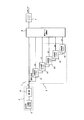
- FIG. 7 is a configuration diagram of a signal level detection device according to a modification.
- FIG. 8 is a diagram showing an example of frequency phase characteristics of a level calculation signal for obtaining a good signal level with respect to an original signal of 0.1 Hz to 20 Hz.
- the signal level detection device 1 is applied to a device that detects the signal level of a signal indicating the magnitude of vibration of the object M, as shown in FIG.
- the signal level detection apparatus 1 includes a signal generation unit 3 that generates two or more level calculation signals having different phases using an original signal O output from a sensor unit 2 that obtains velocity as vibration information of the object M, and an original And a signal level calculation unit 4 for obtaining a signal level r based on the signal O and each level calculation signal.
- the signal generator 3 generates five level calculation signals L1 to L5.
- vibration information of the object M elastically supported from below by a spring S vertically attached to the base T is sensed by the sensor unit 2, and a signal level detection device 1 is detected from a signal output from the sensor unit 2. The case where the signal level is detected will be described.
- the sensor unit 2 is attached to the object M and detects the vertical speed of the object M. When it is desired to detect the signal level using the left and right vibration information of the object M as a signal, the sensor unit 2 may detect the speed of the object M in the left and right direction.
- the sensor unit 2 only needs to be able to detect the speed in the same direction with respect to the vibration of the object M. For example, when it is desired to detect the signal level of the signal obtained by sensing the vertical and horizontal vibrations of the object M, the sensor unit 2 uses the sensor unit 2 to detect the vertical and horizontal directions of the object M and the paper surface in FIG. It is also possible to detect the speed in the direction excluding the direction penetrating through and to obtain the speed in the two directions of the vertical direction and the horizontal direction.
- the signal level detection device 1 processes a signal obtained from the sensor unit 2 and detects a signal level. Therefore, not only the signal level is obtained from the signal obtained by sensing the vibration of the object M, but also the signal level obtained by sensing the pressure fluctuation in the container, the change in atmospheric pressure, the radio wave, etc. Of course it is also possible to obtain.
- the sensor unit 2 is attached to the object M and detects an acceleration in the vertical direction of the object M, and an integrator that integrates the vertical acceleration detected by the acceleration detector 5 to obtain the vertical speed of the object M. 6.
- the sensor unit 2 outputs the detected vertical velocity of the object M as an original signal O.
- the signal generator 3 is provided with phase change filters F1 to F5 in parallel, and filters the original signal O with the phase change filters F1 to F5.
- the phase change filter may be provided corresponding to the number of level calculation signals. In this case, five phase change filters may be provided corresponding to the level calculation signals L1 to L5.
- the frequency is set.
- the signal generator 3 filters the original signal O with a phase change filter F4 having a transfer function G (s) set by inputting ⁇ 4 as a frequency.
- the level calculation signal L4 is obtained from the original signal O.
- the signal generation unit 3 obtains the level calculation signals L1 to L5 using the phase change filters F1 to F5, and as shown in FIG. 3, with respect to the input of the original signal O of a certain frequency ⁇ , the amplitude
- the five level calculation signals L1 to L5 that are the same and differ only in phase can be easily obtained.
- phase difference between the original signal O and the level calculation signal L1 and the phase difference between the level calculation signals L1 to L4 are equally spaced, but the phase difference between the level calculation signal L4 and the level calculation signal L5 is the original difference.
- the phase difference between the signal O and the level calculation signal L1 and the phase difference between the level calculation signals L1 to L4 are different. This is a characteristic in which the frequency phase characteristics of the level calculation signals L1 to L4 change from the upper limit of 0 degrees to the lower limit of -180 degrees as shown in FIG. It is because it is restricted by.
- the phase of the level calculation signals L1 to L5 is 0 degrees or near 0 degrees when the frequency of the original signal O is extremely low, and is ⁇ 180 degrees when the frequency of the original signal O is extremely high frequency— Near 180 degrees. Therefore, as shown in FIG. 3, in the level calculation signals L1 to L4, the phase differences are arranged at equal intervals, and in the level calculation signal L5, the phase is close to ⁇ 180 degrees and the adjacent level calculation signal The phase difference with L4 becomes small.
- the transfer function G (s) of the phase change filters F1 to F5 may be set by the following equation (2).
- O (s) represents the Laplace transform amount of the original signal O
- s represents the Laplace operator
- ⁇ 1 to ⁇ 5 are different from each other.
- the frequency is set.
- the phase change filters F1 to F5 may be secondary low-pass filters.
- the transfer functions G (s) of the phase change filters F1 to F5 may be set by the following equation (3).
- O (s) represents the Laplace transform amount of the original signal O
- s represents the Laplace operator
- ⁇ represents the attenuation rate
- the frequency is shown, and different cutoff frequencies from ⁇ 1 to ⁇ 5 are set.
- the phase of the level calculation signals L1 to L5 can be delayed with respect to the original signal O, and when the high-pass filter is used, the level calculation signals L1 to L5 The phase of L5 can be advanced. Therefore, it is possible to use a high-pass filter for a part of the phase change filters F1 to F5 and use a low-pass filter for the rest of the phase change filters F1 to F5.
- the signal generator 3 obtains level calculation signals L1 to L5 having different phases from the original signal O. Therefore, a signal delayed by a specified time with respect to the original signal O may be generated as the level calculation signals L1 to L5 without using the above-described filter processing.
- the signal level calculation unit 4 obtains the maximum value among the signals obtained by performing absolute value processing on the original signal O and the level calculation signals L1 to L5.
- the waveforms of the original signal O and the level calculation signals L1 to L5 after the absolute value processing are as shown in FIG. A portion having a negative value in the waveform of .about.L5 is folded back to the positive side around the time axis.
- the absolute values of the original signal O and the level calculation signals L1 to L5 are out of phase with each other. Therefore, even if the original signal O and the level calculation signals L1 to L5 are subjected to absolute value processing, the waveforms of the original signal O and the level calculation signals L1 to L5 after processing are shifted in time.
- the maximum value of the original signal O and the level calculation signals L1 to L5 after absolute value processing is equal to the maximum amplitude of the original signal O or the maximum at any time as shown in FIG. The value approximates the amplitude.
- the maximum value of the original signal O and the level calculation signals L1 to L5 after absolute value processing at time a is the maximum value of the level calculation signal L2.
- the maximum value of the original signal O and the level calculation signals L1 to L5 after the absolute value processing at time b is a value that approximates the value of the maximum amplitude of the original signal O.
- the maximum amplitude of the level calculation signals L1 to L5 is equal to the maximum amplitude at the speed of the original signal O, and the maximum amplitude of the original signal O is equal to the signal level.
- the maximum amplitude of the original signal O indicates the magnitude of the vibration of the object M viewed from the speed as a scale. That is, the maximum value when the original signal O has one cycle becomes the signal level.
- the signal level cannot be obtained in a timely manner, and if the vibration frequency of the object M changes, the frequency of the original signal O changes and the original signal O Since the time required for one cycle changes, the maximum amplitude cannot be obtained.
- the original signal after absolute value processing is calculated when the signal level r is calculated.
- One of O and the level calculation signals L1 to L5 can be expected to be the maximum value or a value close to the maximum value. Therefore, by obtaining the maximum value of the original signal O after absolute value processing and the level calculation signals L1 to L5 and setting it as the signal level r, the signal level r is the value of the maximum amplitude of the original signal O itself, It can be obtained as an approximate value.
- the level calculation signals L1 to L5 having phases different from those of the original signal O and the original signal O are input.
- the maximum value at the time of calculation is obtained as the signal level r.
- the signal level r is a value of the maximum amplitude of the original signal O or a value approximated thereto. That is, even if the frequency of the original signal O changes, a value approximate to the value of the maximum amplitude of the original signal O can be obtained as the signal level r.
- phase differences between the level calculation signals L1 to L5 are equally spaced, but the phase difference between the original signal O and the level calculation signal L1 is the phase difference between the level calculation signals L1 to L5. And different. This is because, as shown in FIG. 4, although the phase of the original signal O is constant at 0 degrees, the phase of the level calculation signal L1 is limited to the upper limit of 0 degrees as the frequency decreases. For this reason, the phase of the level calculation signal L1 approaches 0 degrees, and the phase difference from the original signal O becomes small.
- the phase difference between the level calculation signal L1 and the adjacent level calculation signal L2 is also small.
- a value approximate to the value of the maximum amplitude of the original signal O can be obtained as the signal level r by the level calculation signals L2 to L5 in which the phase difference is equally spaced.
- the signal level detection device 1 even if the frequency of the original signal O changes, the value of the maximum amplitude of the original signal O or a value approximated thereto is set as the signal level r in real time and in a timely manner. Can be sought. Therefore, the signal level r can be obtained with high accuracy for signals in a wide frequency band.
- the signal level detection device and the signal level detection method according to the present embodiment even if the frequency of the original signal O changes, the signal level r can be obtained in real time and in a timely manner. Therefore, the signal level r suitable for control with a wide frequency band can be detected.
- the original signal O is a speed that is vibration information of the object M. Therefore, by detecting the signal level r as described above, the magnitude (vibration level) of the vibration of the object M can be detected in a timely and real time manner. Since the vibration level obtained in this way has little time delay with respect to the vibration of the object M, for example, the vibration level can sufficiently withstand use for vehicle vibration suppression control.
- the signal level r is obtained using the original signal O and the level calculation signals L1 to L5.
- three or more level calculation signals having different phases in the frequency band in which the signal level r is desired are obtained. If generated from the signal O, the signal level r can be obtained with high accuracy. Therefore, the signal level calculation unit 4 may obtain the signal level r by executing the above procedure using only the level calculation signal without using the original signal O.
- phase change filters F1 to F5 process the original signal O in parallel to obtain level calculation signals L1 to L5.
- the phase change filters F1 to F5 are arranged in series. It is also possible to do.
- the original signal O is processed by the phase change filter F1 to obtain the level calculation signal L1
- the level calculation signal L1 is processed by the phase change filter F2 to obtain the level calculation signal L2.
- the level calculation signal processed by the immediately preceding phase change filter is processed by the immediately following phase change filter to obtain the level calculation signal.
- the frequency phase characteristic of the level calculation signal changes in the range from 0 degrees as the upper limit to -180 degrees as the lower limit, approaches 0 degrees when the frequency is lowered, and -180 when the frequency is increased. It is getting closer. Therefore, for a high frequency ⁇ , the original signal O and the phase of the level calculation signals L1 to L4 are equally spaced, and the maximum amplitude of the original signal O or a signal level r having a value approximate to this can be obtained. it can. Further, for the low frequency ⁇ , the phases of the level calculation signals L1 to L5 are equally spaced, and the maximum amplitude of the original signal O or a signal level r having a value approximate thereto can be obtained.
- the signal level r can be accurately detected with respect to the original signal O from the high frequency ⁇ to the low frequency ⁇ .
- the original signal O and the level calculation signals L1 to L4 generated by the phase change filters F1 to F4 contribute to the detection of the signal level r with respect to the original signal O of the frequency ⁇ .
- the phase change filters F1 to F5 contribute to the detection of the signal level r with respect to the original signal O of the frequency ⁇ .
- the original signal O when using the original signal O together with the level calculation signal, at least two of the original signal O and the original signal O are within the range from the lower limit to the upper limit of the frequency band. It is preferable that the above level calculation signals are dispersed with equal phase differences within a range of 180 degrees. In addition, when the signal level is obtained using only the level calculation signal, it is preferable that at least three or more level calculation signals are dispersed with equal phase differences within a range of 180 degrees.
- the number of filters that generate the level calculation signal may be determined according to the number of level calculation signals generated.
- the original signal and the two or more level calculation signals may be dispersed at equal intervals within a range of 180 degrees.
- the signal level r can be detected with high accuracy with respect to the input of the original signal in the band of 0.1 Hz to 20 Hz.
- the level calculation signals L1 to L5 that contribute to the detection of the original signal O and the signal level r are dispersed within a range of 180 degrees with a phase difference of 60 degrees or less. As described above, if the signal generator 3 generates the level calculation signals L1 to L5, the signal level r can be detected for signals in a wide frequency band, and the accuracy is improved.
- the signal generation unit 3 When the original signal O is used only for the generation of the level calculation signal, the signal generation unit 3 outputs the level calculation signals L1 to L5 that contribute to the detection of the signal level r within the range of 180 degrees to 60 degrees. If the signals are generated so as to be dispersed with the following equal-interval phase differences, the signal level r can be detected for signals in a wide frequency band, and the accuracy is improved.
- the second or third largest value may be used as the signal level r, or the average value of the maximum value and the second largest value may be used as the signal level r. There is no practical problem.
- the signal is a sine wave and 12 level calculation signals are generated with a phase difference of 15 degrees
- the signal level r is It does not fall below 0.9 times the wave height of the original signal O of the object. Therefore, a good signal level r can be obtained.
- the maximum value of the absolute values of the level calculation signal is the value closest to the actual signal level r. For this reason, it is preferable to obtain the maximum value as the signal level r.
- the absolute value processing is performed on the original signal O and the level calculation signals L1 to L5, so that the signal level r approximates the maximum amplitude of the original signal O even when the sign of the original signal O is negative. It becomes easy to become. Therefore, the signal level r can be detected with higher accuracy.
- the signal level detection device 1 is used as hardware resources (not shown), for example, an A / D converter for taking in a signal output from the acceleration detector 5 and processing necessary for detecting the signal level r.
- a storage device such as a ROM (Read Only Memory) in which a program to be stored is stored, a calculation device such as a CPU (Central Processing Unit) that executes processing based on the program, and a RAM that provides a storage area for the CPU ( And a storage device such as Random Access Memory.
- the signal level detection apparatus 1 can implement
- the obtained signal level r is a vibration level with the speed of the object M as a scale.
- the vibration level based on the acceleration can be obtained.
- the vibration information of the object M is the displacement and the signal level r is obtained using this as the original signal O, the vibration level with the displacement as a scale can be obtained.
- the vehicle body When the signal level detection device 1 according to this embodiment is applied to a vehicle and the signal level is detected as a vibration level of a sprung member in the vehicle, the vehicle body has a sprung resonance frequency of 1 to 2 Hz. In addition to the vibration of the unsprung resonance frequency of 10 to 20 Hz, vibration of around 0.1 Hz may be input during steering. According to this embodiment, even when vibrations in a wide frequency band from 0.1 Hz to 20 Hz are input to the sprung member in this way, the vibration level of the sprung member is controlled regardless of the frequency. It can be detected with high accuracy.
- the signal level (vibration level) is obtained using the vibration information of the object M in the spring mass system in which the object M is supported by the spring S as a signal.
- the vibration level of the object M can also be obtained.
- the signal level detection device 1 determines the rotation direction in the rotational direction depending on the operation state of the passenger in addition to the vibration levels of the sprung member and the unsprung member of the vehicle. It is also suitable for detecting the vibration level of a handle whose vibration frequency varies greatly each time.
- the vibration information of the rotation angle, angular velocity, and angular acceleration of the handle is detected as a signal, and the vibration level at the rotation of the handle is obtained by measuring either the rotation angle, the angular velocity, or the angular acceleration. Is also possible.
- the signal level detection device 1 can determine the vibration level of a vibrating device by itself in a vehicle in which vibrations in a wide frequency band act, and is optimal for the vehicle. It is also possible to select a plurality of vibration information as signals and process them with one signal level detection device 1 to obtain the vibration level of each information.
- the signal level detection device and the signal level detection method according to the present embodiment are also suitable for vehicles other than automobiles, for example, railway vehicles. Moreover, it is also possible to apply to the detection of the vibration level of a building, and it is also possible to obtain a signal level by processing various signals output from a sensor or the like.
Landscapes
- Engineering & Computer Science (AREA)
- Mechanical Engineering (AREA)
- General Engineering & Computer Science (AREA)
- Physics & Mathematics (AREA)
- Acoustics & Sound (AREA)
- Aviation & Aerospace Engineering (AREA)
- Measurement Of Mechanical Vibrations Or Ultrasonic Waves (AREA)
- Vehicle Body Suspensions (AREA)
- Vibration Prevention Devices (AREA)
- General Physics & Mathematics (AREA)
Abstract
Description



Claims (16)
- 信号の大きさである信号レベルを検知する信号レベル検知装置であって、
入力されるオリジナル信号を利用して、位相が異なる複数のレベル算出信号を生成する信号生成部と、
前記オリジナル信号および二つ以上の前記レベル算出信号、あるいは三つ以上の前記レベル算出信号に基づいて前記信号レベルを求める信号レベル演算部と、
を備える信号レベル検知装置。 - 請求項1に記載の信号レベル検知装置であって、
前記信号レベル演算部は、前記オリジナル信号および前記二つ以上のレベル算出信号の最大値、あるいは前記三つの以上のレベル算出信号の最大値を前記信号レベルとする、
信号レベル検知装置。 - 請求項1に記載の信号レベル検知装置であって、
前記信号レベル演算部は、前記オリジナル信号および前記二つ以上のレベル算出信号、あるいは前記三つの以上のレベル算出信号を絶対値処理し、絶対値処理して得た前記オリジナル信号および前記二つ以上のレベル算出信号の最大値、あるいは絶対値処理して得た前記三つの以上のレベル算出信号の最大値を前記信号レベルとする、
信号レベル検知装置。 - 請求項1に記載の信号レベル検知装置であって、
前記信号生成部は、前記オリジナル信号と振幅が等しい前記レベル算出信号を生成する、
信号レベル検知装置。 - 請求項1に記載の信号レベル検知装置であって、
前記信号レベル演算部で求めた前記信号レベルを濾波するローパスフィルタをさらに備える、
信号レベル検知装置。 - 請求項1に記載の信号レベル検知装置であって、
前記信号生成部は、複数の位相変更フィルタを備え、当該位相変更フィルタで前記オリジナル信号を処理して当該オリジナル信号に対して位相の異なる前記レベル算出信号を生成する、
信号レベル検知装置。 - 請求項6に記載の信号レベル検知装置であって、
前記複数の位相変更フィルタは、並列に設けられてそれぞれ前記レベル算出信号を生成する、
信号レベル検知装置。 - 請求項6に記載の信号レベル検知装置であって、
前記複数の位相変更フィルタは、直列に設けられてそれぞれ前記レベル算出信号を生成する、
信号レベル検知装置。 - 請求項6に記載の信号レベル検知装置であって、
前記位相変更フィルタの伝達関数G(s)は、ラプラス演算子をsとし、周波数をωとすると、式(1)、あるいは式(2)で設定され、
前記信号生成部は、生成する前記レベル算出信号毎に前記周波数ωの値を変更して、前記オリジナル信号から前記レベル算出信号を生成する、
信号レベル検知装置。


- 請求項1に記載の信号レベル検知装置であって、
前記複数のレベル算出信号のうち前記信号レベルの検知に寄与する前記二つ以上のレベル算出信号は、前記オリジナル信号および前記二つ以上のレベル算出信号が180度の位相範囲内で等間隔の位相差を持つように生成される、
信号レベル検知装置。 - 請求項1に記載の信号レベル検知装置であって、
前記複数のレベル算出信号のうち前記信号レベルの検知に寄与する前記三つ以上のレベル算出信号は、180度の位相範囲内で等間隔の位相差を持つように生成される、
信号レベル検知装置。 - 請求項10に記載の信号レベル検知装置であって、
前記位相差は60度以下である、
信号レベル検知装置。 - 請求項11に記載の信号レベル検知装置であって、
前記位相差は60度以下である、
信号レベル検知装置。 - 請求項1に記載の信号レベル検知装置であって、
前記信号は、変位、速度、加速度、回転角、角速度、および角加速度のうちから任意に選択される一つまたは複数の信号である、
信号レベル検知装置。 - 信号の大きさである信号レベルを検知する信号レベル検知方法であって、
オリジナル信号から、位相が異なる複数のレベル算出信号を生成する信号生成ステップと、
前記オリジナル信号および前記複数のレベル算出信号、あるいは前記複数のレベル算出信号に基づいて、前記信号レベルを求めるレベル演算ステップと、
を含む信号レベル検知方法。 - 請求項15に記載の信号レベル検知方法であって、
前記レベル演算ステップは、前記オリジナル信号および二つ以上の前記レベル算出信号の最大値、あるいは三つ以上の前記レベル算出信号の最大値を前記信号レベルとする、
信号レベル検知方法。
Priority Applications (2)
| Application Number | Priority Date | Filing Date | Title |
|---|---|---|---|
| US14/912,629 US20160202112A1 (en) | 2013-09-17 | 2014-07-16 | Signal level detection device and signal level detection method |
| DE112014004263.3T DE112014004263T5 (de) | 2013-09-17 | 2014-07-16 | Signalpegeldetektionsvorrichtung und Signalpegeldetektionsverfahren |
Applications Claiming Priority (2)
| Application Number | Priority Date | Filing Date | Title |
|---|---|---|---|
| JP2013-192086 | 2013-09-17 | ||
| JP2013192086A JP6239910B2 (ja) | 2013-09-17 | 2013-09-17 | 信号レベル検知装置および信号レベル検知方法 |
Publications (1)
| Publication Number | Publication Date |
|---|---|
| WO2015040945A1 true WO2015040945A1 (ja) | 2015-03-26 |
Family
ID=52688605
Family Applications (1)
| Application Number | Title | Priority Date | Filing Date |
|---|---|---|---|
| PCT/JP2014/068869 Ceased WO2015040945A1 (ja) | 2013-09-17 | 2014-07-16 | 信号レベル検知装置および信号レベル検知方法 |
Country Status (4)
| Country | Link |
|---|---|
| US (1) | US20160202112A1 (ja) |
| JP (1) | JP6239910B2 (ja) |
| DE (1) | DE112014004263T5 (ja) |
| WO (1) | WO2015040945A1 (ja) |
Families Citing this family (1)
| Publication number | Priority date | Publication date | Assignee | Title |
|---|---|---|---|---|
| US11326664B2 (en) * | 2019-06-07 | 2022-05-10 | GM Global Technology Operations LLC | Control of real-time damper in a sprung mass system |
Citations (2)
| Publication number | Priority date | Publication date | Assignee | Title |
|---|---|---|---|---|
| JP2011225040A (ja) * | 2010-04-16 | 2011-11-10 | Nissan Motor Co Ltd | サスペンション制御装置 |
| JP2013154801A (ja) * | 2012-01-31 | 2013-08-15 | Nissan Motor Co Ltd | 車両の制御装置 |
-
2013
- 2013-09-17 JP JP2013192086A patent/JP6239910B2/ja active Active
-
2014
- 2014-07-16 DE DE112014004263.3T patent/DE112014004263T5/de not_active Withdrawn
- 2014-07-16 US US14/912,629 patent/US20160202112A1/en not_active Abandoned
- 2014-07-16 WO PCT/JP2014/068869 patent/WO2015040945A1/ja not_active Ceased
Patent Citations (2)
| Publication number | Priority date | Publication date | Assignee | Title |
|---|---|---|---|---|
| JP2011225040A (ja) * | 2010-04-16 | 2011-11-10 | Nissan Motor Co Ltd | サスペンション制御装置 |
| JP2013154801A (ja) * | 2012-01-31 | 2013-08-15 | Nissan Motor Co Ltd | 車両の制御装置 |
Also Published As
| Publication number | Publication date |
|---|---|
| JP6239910B2 (ja) | 2017-11-29 |
| JP2015059761A (ja) | 2015-03-30 |
| DE112014004263T5 (de) | 2016-06-23 |
| US20160202112A1 (en) | 2016-07-14 |
Similar Documents
| Publication | Publication Date | Title |
|---|---|---|
| US9963006B2 (en) | Damper control device | |
| JP5652053B2 (ja) | 車体振動推定装置およびこれを用いた車体制振制御装置 | |
| JP7422065B2 (ja) | 路面平坦性計測装置、路面平坦性計測システム、方法、および、プログラム | |
| JP6606320B2 (ja) | 信号レベル検知装置 | |
| JP6031025B2 (ja) | ダンパ制御装置 | |
| JP5652055B2 (ja) | 車体振動推定装置およびこれを用いた車体制振制御装置 | |
| CN103180707A (zh) | 利用光学成像技术测量阻尼的方法 | |
| CA2898093C (en) | Vibration control device | |
| JP2016002844A (ja) | 車両のばね上−ばね下相対速度推定装置 | |
| CN108007475B (zh) | 微机电系统装置测试系统和方法 | |
| US20210041772A1 (en) | Method for suppressing vibration of gimbal, and gimbal | |
| CN110072762A (zh) | 用于检测对方向盘的手动操控的装置和方法 | |
| JP6939660B2 (ja) | 車両走行制御システム | |
| JP5447010B2 (ja) | 乗り物酔い抑制制御装置及びその制御方法 | |
| JP2019051781A (ja) | ばね下振動検知装置およびサスペンション制御装置 | |
| WO2015040945A1 (ja) | 信号レベル検知装置および信号レベル検知方法 | |
| JP2019018773A (ja) | サスペンションの制御システム | |
| CN110509978B (zh) | 一种驾驶模式切换方法及系统 | |
| US12227409B2 (en) | Robust inertial sensor self-test | |
| WO2019003455A1 (ja) | 懸架装置用の制御装置、微分量算出装置、記録媒体および懸架システム | |
| JP2014238320A (ja) | タイヤの評価方法 | |
| JP2009006742A (ja) | 操舵装置及び操舵反力設定方法 | |
| Flore et al. | Dynamic Mechanical Analysis of an Aircraft Wing with emphasis on vibration modes change with loading | |
| JP2015175405A (ja) | 能動型制振装置 | |
| EP2966409B1 (en) | Systems and methods for inertial reference system alignment |
Legal Events
| Date | Code | Title | Description |
|---|---|---|---|
| 121 | Ep: the epo has been informed by wipo that ep was designated in this application |
Ref document number: 14845818 Country of ref document: EP Kind code of ref document: A1 |
|
| WWE | Wipo information: entry into national phase |
Ref document number: 14912629 Country of ref document: US |
|
| WWE | Wipo information: entry into national phase |
Ref document number: 1120140042633 Country of ref document: DE Ref document number: 112014004263 Country of ref document: DE |
|
| 122 | Ep: pct application non-entry in european phase |
Ref document number: 14845818 Country of ref document: EP Kind code of ref document: A1 |