WO2015040885A1 - 検眼装置 - Google Patents
検眼装置 Download PDFInfo
- Publication number
- WO2015040885A1 WO2015040885A1 PCT/JP2014/062706 JP2014062706W WO2015040885A1 WO 2015040885 A1 WO2015040885 A1 WO 2015040885A1 JP 2014062706 W JP2014062706 W JP 2014062706W WO 2015040885 A1 WO2015040885 A1 WO 2015040885A1
- Authority
- WO
- WIPO (PCT)
- Prior art keywords
- measurement
- eye
- subjective
- objective
- display screen
- Prior art date
- Legal status (The legal status is an assumption and is not a legal conclusion. Google has not performed a legal analysis and makes no representation as to the accuracy of the status listed.)
- Ceased
Links
Images








Classifications
-
- A—HUMAN NECESSITIES
- A61—MEDICAL OR VETERINARY SCIENCE; HYGIENE
- A61B—DIAGNOSIS; SURGERY; IDENTIFICATION
- A61B3/00—Apparatus for testing the eyes; Instruments for examining the eyes
- A61B3/10—Objective types, i.e. instruments for examining the eyes independent of the patients' perceptions or reactions
- A61B3/103—Objective types, i.e. instruments for examining the eyes independent of the patients' perceptions or reactions for determining refraction, e.g. refractometers, skiascopes
-
- A—HUMAN NECESSITIES
- A61—MEDICAL OR VETERINARY SCIENCE; HYGIENE
- A61B—DIAGNOSIS; SURGERY; IDENTIFICATION
- A61B3/00—Apparatus for testing the eyes; Instruments for examining the eyes
- A61B3/10—Objective types, i.e. instruments for examining the eyes independent of the patients' perceptions or reactions
- A61B3/107—Objective types, i.e. instruments for examining the eyes independent of the patients' perceptions or reactions for determining the shape or measuring the curvature of the cornea
Definitions
- the present invention relates to an improvement in an optometry apparatus capable of performing measurement by objective test and measurement by subjective test.
- an optometry apparatus projects a measurement pattern onto an eye to be examined, performs measurement by an objective test based on the measurement pattern projected onto the eye to be examined, and presents a visual target to the subject to perform a subjective test. What performs a measurement is known (for example, refer patent document 1).
- the examiner performs the subjective test after aligning the device body while observing the anterior segment image on the display screen and performing the objective test.
- the measurement value as the measurement result by the other subjective examination and the measurement value as the measurement result by the subjective examination are displayed on the display screen.
- the measured value by the objective test is displayed only at the objective test, and by the subjective test.
- the measured value is displayed only during the subjective test. That is, the measurement value by the objective test and the measurement value by the subjective test are not displayed on the display screen at the same time.
- the left eye measurement and the right eye measurement are separately performed in the objective test and the subjective test. Also in this case, only the measurement result of the left eye is displayed on the display screen when measuring the left eye, and only the measurement result of the right eye is displayed on the display screen when measuring the right eye.
- the measurement result of the eye that performed the measurement first Is not displayed, and it is inconvenient if the examiner wants to confirm the measurement result of the person who performed the inspection first during the measurement because the measurement result is not displayed on the display screen. For example, when the measurement result of the right eye and the measurement result of the left eye are significantly different, this cannot be confirmed, which is inconvenient.
- the present invention has been made in view of the above circumstances, and its purpose is to display the measurement result of the other eye during measurement of one eye during objective measurement, and to perform subjective measurement. It is an object of the present invention to provide an optometry apparatus capable of displaying a measurement result by objective measurement.
- An optometry apparatus includes an observation system for observing the anterior eye portion of a subject eye, a fixation target projection system for presenting a fixation target to the subject eye, a measurement pattern projected onto the fundus of the subject eye, and the subject eye
- An objective measurement system for receiving a measurement pattern projected on the fundus of the eye, a subjective measurement system for presenting a subjective visual target to the eye to be examined, an objective measurement by the objective measurement system, and the subjective measurement
- a processing unit that executes processing of subjective measurement by the system, and a display unit that is connected to the processing unit and displays the measurement result of the objective measurement and the measurement result of the subjective measurement.
- the processing unit displays a measurement result of one eye on the display screen when measuring one eye by the objective measurement, and the other eye after the measurement of the one eye is completed.
- a display step of displaying the measurement result of the one eye on the display screen during the measurement of the eye, and a display step of displaying the measurement result of the binocular by the objective test on the display screen after the measurement of both eyes is completed.
- the measurement result of one eye is displayed on the display screen during the measurement of the other eye after the measurement of one eye is completed. It is convenient to be able to check the measurement results of the eye already performed at any time.
- the measurement result is displayed on the display screen as needed, so that the examiner can be prevented from forgetting to measure.
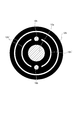
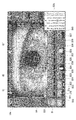
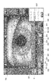
- FIG. 7 is a plan view of the kerato plate shown in FIGS. 3 to 6. It is explanatory drawing which shows the state by which the measurement result of the objective measurement of the right eye is displayed during the measurement of the left eye of objective measurement. It is explanatory drawing which shows the state in which the measurement result of both eyes by objective measurement and the measurement result of the right eye by subjective test are displayed during measurement of the left eye of subjective measurement. It is explanatory drawing which shows an example of the display screen at the time of a near vision test. It is explanatory drawing which shows an example of the display screen at the time of a distance vision test.
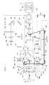
- FIG. 1 is a schematic diagram showing the overall configuration of an optometry apparatus according to the present invention.
- reference numeral 1 denotes an optometry apparatus.
- the optometry apparatus 1 is schematically configured by a base 2, a gantry 3 that can be moved back and forth and left and right with respect to the base 2, a head portion 4 that is integral with the gantry 3, and a face receiving portion 5 that is integral with the base 2. ing.
- the face receiving portion 5 is provided with a chin rest 6 and a forehead rest 7.
- the face of the subject (not shown) is fixed by the face receiving portion 5.
- a joystick 8 is provided on the gantry 3.
- the head unit 4 is moved back and forth and left and right with respect to the subject by the joystick 8.
- the head unit 4 is moved in the vertical direction by rotating the joystick 8 with respect to its axis.
- the head unit 4 is provided with a processing unit 9 and a liquid crystal display device (LCD monitor) as the display unit 10 shown in FIG.
- the display unit 10 has a touch panel display screen 10a.
- the processing unit 9 is connected with a spectacle lens measurement device 11 so that the lens power as measurement data of the spectacle lens worn by the subject can be input.
- the head unit 4 includes an observation system 12 for observing the anterior eye part of the eye E, a fixation target projection system 13 for presenting the fixation target to the eye E, and a target.
- An objective measurement system 14 that projects a measurement pattern (not shown) on the fundus oculi Ef of the optometry and receives the measurement pattern projected on the fundus oculi Ef of the eye E to be examined, and a subjective visual target for the eye E to be examined
- a subjective measurement system 15 is provided.
- the fixation target projection system 13 and the subjective measurement system 15 share the optical elements constituting the optical system.
- the observation system 12 is roughly composed of an objective lens 12a, a dichroic filter 12b, a half mirror 12c, a relay lens 12d, a dichroic filter 12e, an imaging lens 12f, and an image sensor (CCD) 12g.
- the light reception output of the image sensor 12 g is input to the processing unit 9.
- the anterior segment image E ′ is displayed on the display screen 10 a of the display unit 10.
- a kerato plate 12h for projecting a corneal shape measurement ring-shaped light beam (not shown) on the cornea C of the eye E shown in FIG. 7 is provided immediately in front of the objective lens 12a.
- a pair of alignment systems 16 that perform alignment in the optical axis direction of the observation system 12 with respect to the eye E are provided behind the kerato plate 12h, as shown in FIGS.
- This alignment system 16 is roughly composed of an alignment light source 16a and a projection lens 16b that projects the light beam of the alignment light source 16a onto the cornea C of the eye E as a parallel light beam.
- the observation system 12 is provided with an alignment system 17 that performs vertical and horizontal alignment of the head unit 4 with respect to the eye E.
- the alignment system 17 is generally composed of an alignment light source 17a and a projection lens 17b that projects the light beam of the alignment light source 17a onto the cornea C of the eye E to be examined.
- the head portion 4 is moved up and down and left and right using the joystick 8 while visually recognizing the bright spot image of the alignment light source 17a formed on the cornea C, thereby causing the head portion 4 to move up and down and left and right (XY directions). Can be aligned.
- the alignment mark AL and the bright spot image Br are shown on the display screen 10a in FIG.
- the alignment in the optical axis direction is performed by moving to the position where the bright spot image Br of the alignment light source 17a is in focus.
- the measurement may be automatically started when the ratio between the distance between the two bright spot images of the alignment light source 16a and the diameter of the keratling image is within a predetermined range.
- the amount of alignment deviation may be obtained from this ratio, and this amount of alignment deviation may be displayed on the display screen 10a.
- the head unit (measuring head) 4 may be driven by a motor, and automatic alignment may be performed using information on the amount of misalignment.
- the fixation target projection system 13 includes an LED light source 13a that generates white light, a color correction filter 13b, a collimator lens 13b ′, a chart plate 13c, a half mirror 13d, a relay lens 13e, a reflection mirror 13f, The focusing lens 13g, a relay lens 13h, a field lens 13i, a variable cross cylinder lens (VCC) 13j, a reflecting mirror 13k, dichroic filters 13m and 12b, and an objective lens 12a are schematically configured.
- the subjective measurement system 15 is provided with a glare light source 13n for irradiating the eye E with glare light.
- the chart plate 13c is formed with a landscape chart (not shown) for presenting a fixation target to the eye E and a plurality of target charts for measuring visual acuity values during subjective measurement. Yes.
- the landscape chart is projected onto the fundus oculi Ef of the eye E, the subject is fixed to the landscape chart, alignment is performed, and the eye refractive power is measured in the cloudy vision state.
- the objective measurement system 14 includes a ring-shaped luminous flux projection system 14 ⁇ / b> A that projects a ring-shaped measurement pattern onto the fundus oculi Ef of the eye E to be examined, and a ring shape reflected on the fundus oculi Ef of the eye E to be examined. And a ring-shaped light beam receiving system 14B for receiving the measurement pattern.
- the ring-shaped luminous flux projection system 14A includes a reflex measurement unit 14a, a relay lens 14b, a pupil ring 14c, a field lens 14d, a perforated prism 14e, a rotary prism 14f, dichroic filters 13m and 12b, an objective.
- the lens 12a is schematically configured.
- the reflex measurement unit 14a includes a reflex measurement light source (LED) 14h, a collimator lens 14i, a conical prism 14j, and a ring-shaped measurement pattern forming plate 14k.
- the ring-shaped light beam receiving system 14B includes an objective lens 12a, a dichroic filter 12b, a dichroic filter 13m, a rotary prism 14f, a perforated prism 14e, a field lens 14m, a reflection mirror 14n, a relay lens 14p, It comprises a focusing lens 14q, a reflecting mirror 14r, a dichroic filter 12e, an imaging lens 12f, and an image sensor (CCD) 12g.
- an objective lens 12a a dichroic filter 12b, a dichroic filter 13m, a rotary prism 14f, a perforated prism 14e, a field lens 14m, a reflection mirror 14n, a relay lens 14p, It comprises a focusing lens 14q, a reflecting mirror 14r, a dichroic filter 12e, an imaging lens 12f, and an image sensor (CCD) 12g.
- CCD image sensor
- the variable cylinder lens 13j, the display unit 10 and the like are controlled by the processing unit 9.
- the dichroic filter 12b has a role of transmitting the corneal shape measurement ring-shaped light beam projected onto the cornea C and the light beams of the alignment light sources 16a and 17a.
- an anterior eye image E ′, a virtual image (not shown), and a bright spot image Br are formed on the image sensor 12g according to the lighting. .
- the light source 14h is turned on. Further, the unit portion 14a of the ring-shaped light beam projection system 14A is moved in the optical axis direction, and the focusing lens 14q of the ring-shaped light beam light receiving system 14B is correspondingly moved in the optical axis direction.
- the ring-shaped measurement pattern is reflected by the relay lens 14b, the pupil stop 14c, the field lens 14d, and the reflection surface 14e 'of the perforated mirror 14e, and is guided to the dichroic filter 13m. Then, after being reflected by the dichroic mirror 13m, it is guided to the objective lens 12a via the dichroic mirror 12b, and a ring-shaped light beam is projected onto the fundus oculi Ef of the eye E to be examined.
- the ring-shaped measurement pattern formed on the fundus oculi Ef of the eye E is condensed by the objective lens 12a, and the holes of the dichroic filters 12b and 13m, the rotary prism 14f, and the perforated mirror 14e. 14e ′′, the field lens 14m, the reflection mirror 14n, the relay lens 14p, the focusing lens 14q, the reflection mirror 14r, the dichroic mirror 12e, and the imaging lens 12f, and is imaged on the imaging element 12g.
- An image (not shown) of a ring-shaped measurement pattern is formed on 12g.
- the processing unit 9 When the subjective measurement is set by the processing unit 9, as shown in FIG. 6, the light source 13a is turned on, and the chart plate 13c is illuminated via the color correction filter 13b. Various charts described later are provided on the chart plate 13c. Further, the focusing lens 13g is set at a position corresponding to the eye refractive power measurement result. Similarly, the variable cylindrical lens 13j is set so as to correct astigmatism of the subject's eye measured at the time of eye refractive power.
- the luminous flux of the target is a half mirror 13d, a relay lens 13e, a reflecting mirror 13f, a focusing lens 13g, a relay lens 13h, a field lens 13i, and a variable cylindrical lens. 13j, the reflecting mirror 13k, the dichroic filters 13m and 12b, and the objective lens 12a, and then projected onto the fundus oculi Ef of the eye E to be examined.
- the subject responds to the examiner's question about the appearance of the optotype, and the examiner determines the prescription value based on the presence or absence of the appearance of the optotype.
- the subjective measurement is performed with the glare light source 13n turned on.
- an operation button is displayed as shown in FIG.
- a switching button B1 for switching between the objective measurement and the subjective measurement a switching button B2 for simultaneously measuring the reflex mode and the kerato mode, and switching between the reflex mode and the kerato mode, and measuring the eye of the cataract are performed.
- Operation button B3 at the time of operation operation button B4 for adjusting the brightness of the fixation target, switching button B5 for switching between cloud vision for the first time only and cloudy vision for each measurement, and detailed confirmation of the measurement result Operation button B6 for performing, operation button B7 for printing out the measurement result, operation button B8 for measuring the diameter of cornea C, operation button B9 for clearing eye refractive power measurement data, auto A manual switching button B10 is displayed.
- the display screen 10a displays a sign “R” meaning a measurement value of the right eye, a sign “L” meaning a measurement value of the left eye, a patient ID, a measurer ID, and the like.
- the processing unit 9 executes an instruction corresponding to the operation by operating these operation buttons B1 to B10.
- the display screen 10a of the display unit 10 is switched to the screen shown in FIG.
- the display screen 10a includes a switch button B21 for switching the target function between the target designation button 21a and the lattice target button 21b, and switching of the inspection between the distance measurement and the near measurement.
- a reset button B27 and a chart table B26 showing the entire chart presented to the subject and the chart currently presented are displayed.
- FIG. 9 shows a state in which the visual target “D” having the visual acuity value “0.63” is presented to the patient (subject).
- the display screen 10a displays a plurality of designation buttons B31 to B40 for directly designating the visual acuity value when the objective measurement is switched from the objective measurement to the subjective measurement by the switching button B1.
- the processing unit 9 sets a visual target corresponding to the visual acuity value designated by the designation buttons B31 to B40 in the subjective measurement system 15 and uses the designation buttons B31 to B40.
- the designated visual acuity table is displayed on the display screen 10a.
- the visual acuity table B26 ′ for one row is presented to the subject as shown in FIGS.
- the target “RDZT7” for one line corresponding to the visual acuity value “1.0” is displayed. Is set in the optical path of the subjective measurement system 15, and the target “RDZT7” for one line corresponding to the visual acuity value “1.0” is displayed on the display screen 10a.
- the display screen 10a is provided with a confirm button B42 for confirming the visual acuity value displayed on the display screen 10a by operating the designation buttons B31 to B40.
- the examiner can directly set the target in the optical path of the subjective measurement system 15, so for example, an up / down button for sequentially moving the target is provided and the target is moved step by step by operating this up / down button. Therefore, it is more efficient and convenient than setting a visual acuity value.
- the visual acuity value adjacent to the designated visual acuity value is designated as a precaution.
- the stored visual acuity value is the one before the change, which is convenient.
- the designation button 39 is operated and the target “RDZT7” corresponding to the visual acuity value “1.0” is designated, when the subject gives an ambiguous answer for two characters out of five characters.
- the designation button 39 is operated and the target “RDZT7” corresponding to the visual acuity value “1.0” is designated, when the subject gives an ambiguous answer for two characters out of five characters.
- the visual acuity value is changed from the visual acuity value “1.0” to the visual acuity value “0.8”, and if the designation button B40 is designated, the visual acuity value is changed. It is changed from “1.0” to “1.2”. However, if the visual acuity value “1.0” is confirmed and registered by the confirmation button B42, the subject “VSHE4” with the visual acuity value “0.8” looks good, and the visual acuity value “1.2”. When the user makes an answer that the target “HKNS9” cannot be seen well, the measurement can be completed without operating the designation button B39 corresponding to the visual acuity value “1.0” again.
- the processing unit 9 displays the measurement result of the right eye R on the display screen 10a during the measurement of the other eye after the measurement of the one eye, here, during the measurement of the left eye L by the objective measurement. Perform the display step.
- FIG. 8 shows a state in which the measurement result of the right eye is displayed during the measurement of the left eye.
- the switching button B1 When the switching button B1 is operated, the screen is switched from the screen at the time of objective measurement shown in FIG. 8 to the display screen 10a at the time of subjective measurement shown in FIG.
- the processing unit 9 executes a display step of displaying the measurement result of both eyes by the objective test on the display screen 10a.
- the processing unit 9 executes a process of displaying the power of the spectacle lens together with the measurement result by the objective measurement in the subjective measurement.
- the measurement data of the spectacle lens is displayed as indicated by a broken line Q4.
- the processing unit 9 displays the measurement result of one eye on the display screen 10a when measuring one eye by subjective measurement, and is measuring the other eye after the measurement of one eye is completed.
- the display step of displaying the measurement result of one eye on the display screen 10a and the display step of displaying the measurement result of both eyes by the subjective examination on the display screen 10a after the measurement of both eyes are executed.
- the measurement results of the objective test for both eyes (broken lines Q1 ', Q1) and the measurement result of the right eye during the subjective test (see the broken line Q5) are displayed on the display screen 10a. That is, at the time of measuring the right eye, the frequencies S and C and the axis angle A corresponding to the target chart set in the subjective target projection system are displayed simultaneously with the measurement result of both eyes at the time of objective measurement, and the left eye At the time of measurement, the measurement result of the right eye is displayed simultaneously with the measurement result of both eyes at the time of objective measurement.
- the target for one line is presented as shown in FIGS.
- the presentation of the target for one line is used, for example, when performing a near-inspection, a distance-inspection, a contrast test, and a glare test, but is not limited thereto. Since these detailed descriptions are not directly related to the present invention, they are omitted.
- the display screen 10a When the switching button B21 is operated to switch from the target presentation button 21a to the target presentation button 21b, the display screen 10a has a gazing point X1 at the center and a vertical line on the eye to be examined as shown in FIG. A lattice-like visual target X4 configured by X2 and the horizontal line X3 is displayed. Further, the processing unit 9 executes a process of setting a lattice-like target (so-called Amsler chart) X4 in the subjective measurement system 15.
- the central portion may appear distorted.
- the lattice-like visual target X4 looks distorted in this way, it is considered that there is some abnormality in the fundus oculi Ef, which can be used for assistance in fundus examination and the like.
- the lattice-like target X4 is incorporated into the optometry apparatus 1 and presented to the patient, the objectivity of the examination using the lattice-like target X4 can be ensured.
Landscapes
- Life Sciences & Earth Sciences (AREA)
- Health & Medical Sciences (AREA)
- Medical Informatics (AREA)
- Biophysics (AREA)
- Ophthalmology & Optometry (AREA)
- Engineering & Computer Science (AREA)
- Biomedical Technology (AREA)
- Heart & Thoracic Surgery (AREA)
- Physics & Mathematics (AREA)
- Molecular Biology (AREA)
- Surgery (AREA)
- Animal Behavior & Ethology (AREA)
- General Health & Medical Sciences (AREA)
- Public Health (AREA)
- Veterinary Medicine (AREA)
- Eye Examination Apparatus (AREA)
Abstract
本発明の検眼装置は、観察系(12)、固視標投影系(13)、眼底(Ef)に測定パターンを投影しかつ眼底(Ef)に投影された測定パターンを受像する他覚式測定系(14)、被検眼Eに自覚式の視標を提示する自覚式測定系(15)、他覚式測定系(14)による他覚測定、自覚式測定系(15)による自覚測定との処理を実行する処理部(9)、処理部(9)に接続されて他覚測定による測定結果と自覚測定による測定結果とを表示する表示部(10a)を備え、処理部(9)は、他覚測定時に一方の眼の測定を行ったとき、一方の眼の測定結果を表示画面(10a)に表示する表示ステップ、一方の眼の測定終了後他方の眼の測定中に、一方の眼の測定結果を表示画面(10a)に表示する表示ステップ、両眼測定終了後に表示画面(10a)に他覚検査による両眼の測定結果を表示する表示ステップを実行する。
Description
本発明は、他覚検査による測定と自覚検査による測定とを行うことが可能な検眼装置の改良に関する。
従来から、検眼装置には、被検眼に測定パターンを投影して、被検眼に投影された測定パターンにより、他覚検査による測定を行うと共に、被検者に視標を提示して自覚検査による測定を行うものが知られている(例えば、特許文献1参照。)。
この種の装置では、検者は、前眼部像を表示画面上で観察しながら装置本体のアライメントを行い、他覚検査を行った後、自覚検査を行っている。その他覚検査による測定結果としての測定値と、自覚検査による測定結果としての測定値とはその表示画面に表示される。
ところで、この種の装置では、他覚検査による測定と、自覚検査による測定とを行うことができるとはいっても、他覚検査による測定値は他覚検査の際にのみ表示され、自覚検査による測定値は自覚検査の際のみに表示される。すなわち、他覚検査による測定値と自覚検査による測定値とは、表示画面に同時に表示されない構成となっている。
このため、自覚検査を行った後に、再度、検者が他覚検査の測定結果を確認したい場合に不便である。
また、この種の装置では、他覚検査、自覚検査において、左眼の測定と右眼の測定とを別々に行っている。この場合も、左眼の測定のときには左眼の測定結果のみが表示画面に表示され、右眼の測定のときには右眼の測定結果のみが表示画面に表示される。
また、この種の装置では、他覚検査、自覚検査において、左眼の測定と右眼の測定とを別々に行っている。この場合も、左眼の測定のときには左眼の測定結果のみが表示画面に表示され、右眼の測定のときには右眼の測定結果のみが表示画面に表示される。
このため、左眼の測定と右眼の測定とのいずれか一方を先に行った後にいずれか他方の眼の測定を後から行う際に、その測定を先に行った方の眼の測定結果が表示されず、検者が測定中に先に検査を行った方の測定結果を確認したい場合、その測定結果が表示画面上に表示されないため不便である。
例えば、右眼の測定結果と左眼の測定結果とが大幅に異なる場合にこれを確認できず、不便である。
例えば、右眼の測定結果と左眼の測定結果とが大幅に異なる場合にこれを確認できず、不便である。
本発明は、上記の事情に鑑みて為されたもので、その目的は、他覚測定時の一方の眼の測定中に、他方の眼の測定結果を表示することができ、かつ、自覚測定中に、他覚測定による測定結果を表示することのできる検眼装置を提供することにある。
本発明に係る検眼装置は、被検眼の前眼部を観察する観察系と、被検眼に固視標を提示する固視標投影系と、被検眼の眼底に測定パターンを投影しかつ被検眼の眼底に投影された測定パターンを受像する他覚式測定系と、被検眼に自覚式の視標を提示する自覚式測定系と、前記他覚式測定系による他覚測定と前記自覚式測定系による自覚測定との処理を実行する処理部と、前記処理部に接続されて前記他覚測定による測定結果と前記自覚測定による測定結果とを表示する表示部とを備えている。
前記処理部は、前記他覚測定による一方の眼の測定を行ったときに、該一方の眼の測定結果を前記表示画面に表示する表示ステップと、前記一方の眼の測定終了後他方の眼の測定中に、前記一方の眼の測定結果を前記表示画面に表示する表示ステップと、両眼の測定終了後に前記表示画面に前記他覚検査による両眼の測定結果を表示する表示ステップとを実行する。
本発明によれば、一方の眼の測定終了後で他方の眼の測定中に、一方の眼の測定結果が表示画面に表示されているので、検者は他方の眼の測定中に検査をすでに行った方の眼の測定結果を随時確認できて便利である。
また、随時、表示画面に測定結果が表示されるので、検者の測定のし忘れを予防できる。
(検眼装置の外観構成)
図1は本発明に係る検眼装置の全体構成を示す概略図である。この図1において、1は検眼装置を示す。検眼装置1は、ベース2と、このベース2に対して前後左右に移動可能な架台3と、この架台3と一体のヘッド部4と、ベース2と一体の顔受け部5とから概略構成されている。
図1は本発明に係る検眼装置の全体構成を示す概略図である。この図1において、1は検眼装置を示す。検眼装置1は、ベース2と、このベース2に対して前後左右に移動可能な架台3と、この架台3と一体のヘッド部4と、ベース2と一体の顔受け部5とから概略構成されている。
顔受け部5には、顎受け6と額当て7とが設けられている。この顔受け部5により被検者(図示を略す)の顔が固定される。
その架台3には、ジョイスティック8が設けられている。ヘッド部4はこのジョイスティック8により被検者に対して前後左右に移動される。また、ヘッド部4は、ジョイスティック8をその軸に対して回転させることにより上下方向に移動される。
その架台3には、ジョイスティック8が設けられている。ヘッド部4はこのジョイスティック8により被検者に対して前後左右に移動される。また、ヘッド部4は、ジョイスティック8をその軸に対して回転させることにより上下方向に移動される。
(検眼装置1のシステムの構成)
そのヘッド部4には、図2に示す処理部9、表示部10としての液晶表示装置(LCDモニタ)が設けられている。その表示部10はタッチパネル式の表示画面10aを有する。
そのヘッド部4には、図2に示す処理部9、表示部10としての液晶表示装置(LCDモニタ)が設けられている。その表示部10はタッチパネル式の表示画面10aを有する。
処理部9には、図1、図2に示すように、眼鏡レンズ測定装置11が接続され、被検者が装用する眼鏡レンズの測定データとしてのレンズ度数等が入力可能とされている。
(光学系の構成)
ヘッド部4には、図3ないし図6に示すように、被検眼Eの前眼部を観察する観察系12と、被検眼Eに固視標を提示する固視標投影系13と、被検眼の眼底Efに測定パターン(図示を略す)を投影しかつ被検眼Eの眼底Efに投影された測定パターンを受像する他覚式測定系14と、被検眼Eに自覚式の視標を提示する自覚式測定系15とが設けられている。ここでは、固視標投影系13と自覚式測定系15とは、その光学系を構成する光学素子が共用されている。
ヘッド部4には、図3ないし図6に示すように、被検眼Eの前眼部を観察する観察系12と、被検眼Eに固視標を提示する固視標投影系13と、被検眼の眼底Efに測定パターン(図示を略す)を投影しかつ被検眼Eの眼底Efに投影された測定パターンを受像する他覚式測定系14と、被検眼Eに自覚式の視標を提示する自覚式測定系15とが設けられている。ここでは、固視標投影系13と自覚式測定系15とは、その光学系を構成する光学素子が共用されている。
(観察系12の構成)
観察系12は、対物レンズ12aと、ダイクロイックフィルタ12bと、ハーフミラー12cと、リレーレンズ12dと、ダイクロイックフィルタ12eと、結像レンズ12fと、撮像素子(CCD)12gとから概略構成されている。その撮像素子12gの受光出力は、処理部9に入力される。これにより、前眼部像E’が表示部10の表示画面10aに表示される。
観察系12は、対物レンズ12aと、ダイクロイックフィルタ12bと、ハーフミラー12cと、リレーレンズ12dと、ダイクロイックフィルタ12eと、結像レンズ12fと、撮像素子(CCD)12gとから概略構成されている。その撮像素子12gの受光出力は、処理部9に入力される。これにより、前眼部像E’が表示部10の表示画面10aに表示される。
対物レンズ12aの直前方には、図7に示す被検眼Eの角膜Cに角膜形状測定用リング状光束(図示を略す)を投影するケラト板12hが設けられている。ケラト板12hの後方には、図3ないし図6に示すように、被検眼Eに対して観察系12の光軸方向のアライメントを行う一対のアライメント系16が設けられている。
このアライメント系16は、アライメント光源16aと、アライメント光源16aの光束を、被検眼Eの角膜Cに平行光束として投影する投影レンズ16bとから概略構成されている。
観察系12には、被検眼Eに対するヘッド部4の上下左右方向のアライメントを行うアライメント系17が設けられている。このアライメント系17は、アライメント光源17aと、このアライメント光源17aの光束を、被検眼Eの角膜Cに投影する投影レンズ17bとから概略構成される。
その角膜Cに形成されたアライメント光源17aの輝点像を視認しつつジョイスティック8を用いてヘッド部4を上下左右に移動させることにより、被検眼Eに対するヘッド部4の上下左右方向(XY方向)のアライメントを行うことができる。図3の表示画面10aには、そのアライメントマークAL、輝点像Brが示されている。
この実施例では、光軸方向のアライメントは、アライメント光源17aの輝点像Brのピントが合う位置に移動させることにより行っている。しかし、アライメント光源16aの2個の輝点像の間隔とケラトリング像の径の比率が所定範囲にあるとき、自動的に測定を開始させてもよい。また、この比率からアライメントのずれ量を求めて、このアライメントのずれ量を表示画面10aに表示させても良い。また、ヘッド部(測定ヘッド)4をモータにより駆動可能として、アライメントのずれ量の情報を用いて自動的にアライメントする構成としても良い。
(固視標投影系13、自覚式測定系15の構成)
固視標投影系13は、白色光を発生するLED光源13aと、色補正フィルタ13bと、コリメータレンズ13b’と、チャート板13cと、ハーフミラー13dと、リレーレンズ13eと、反射ミラー13fと、合焦レンズ13gと、リレーレンズ13hと、フィールドレンズ13iと、バリアブルクロスシリンダレンズ(VCC)13jと、反射ミラー13kと、ダイクロイックフィルタ13m、12bと、対物レンズ12aとから概略構成されている。なお、その自覚式測定系15には、被検眼Eにグレア光を照射するグレア光源13nが設けられている。
固視標投影系13は、白色光を発生するLED光源13aと、色補正フィルタ13bと、コリメータレンズ13b’と、チャート板13cと、ハーフミラー13dと、リレーレンズ13eと、反射ミラー13fと、合焦レンズ13gと、リレーレンズ13hと、フィールドレンズ13iと、バリアブルクロスシリンダレンズ(VCC)13jと、反射ミラー13kと、ダイクロイックフィルタ13m、12bと、対物レンズ12aとから概略構成されている。なお、その自覚式測定系15には、被検眼Eにグレア光を照射するグレア光源13nが設けられている。
チャート板13cには、被検眼Eに固視標を提示するための風景チャート(図示を略す)と、自覚測定の際の視力値を測定するために複数個の視標チャートとが形成されている。
他覚測定の場合には、その風景チャートが被検眼Eの眼底Efに投影され、被検者にその風景チャートを固視させてアライメントを行い、雲霧視状態で眼屈折力の測定が実行される。
他覚測定の場合には、その風景チャートが被検眼Eの眼底Efに投影され、被検者にその風景チャートを固視させてアライメントを行い、雲霧視状態で眼屈折力の測定が実行される。
他覚式測定系14は、図4に示すように、被検眼Eの眼底Efにリング状の測定パターンを投影するリング状光束投影系14Aと、被検眼Eの眼底Efにおいて反射されたリング状の測定パターンを受像するリング状光束受光系14Bとから概略構成されている。
そのリング状光束投影系14Aは、レフ測定ユニット部14aと、リレーレンズ14bと、瞳リング14cと、フィールドレンズ14dと、穴開きプリズム14eと、ロータリープリズム14fと、ダイクロイックフィルタ13m、12bと、対物レンズ12aとから概略構成されている。そのレフ測定ユニット部14aは、レフ測定用の光源(LED)14hと、コリメータレンズ14iと、円錐プリズム14jと、リング状の測定パターンの形成板14kとから構成されている。
そのリング状光束受光系14Bは、対物レンズ12aと、ダイクロイックフィルタ12bと、ダイクロイックフィルタ13mと、ロータリープリズム14fと、穴開きプリズム14eと、フィールドレンズ14mと、反射ミラー14nと、リレーレンズ14pと、合焦レンズ14qと、反射ミラー14rと、ダイクロイックフィルタ12eと、結像レンズ12fと、撮像素子(CCD)12gとから構成されている。
LED光源13aと、光源14hと、グレア光源13nと、アライメント光源16a、17aと、ケラト盤12hのケラトリング光源12h’と、ユニット部14aと、合焦レンズ13g、14qと、チャート板13cと、バリアブルシリンダレンズ13jと、表示部10等は処理部9によって制御される。
(観察系12、角膜形状測定の際の光路)
ダイクロイックフィルタ12bは、角膜Cに投影された角膜形状測定用リング状光束、アライメント光源16a、17aの光束を透過させる役割を有する。処理部9により、これらのアライメント光源16a、17aが点灯されると、その点灯に応じて、撮像素子12gに前眼部像E’、虚像(図示を略す)、輝点像Brが形成される。
ダイクロイックフィルタ12bは、角膜Cに投影された角膜形状測定用リング状光束、アライメント光源16a、17aの光束を透過させる役割を有する。処理部9により、これらのアライメント光源16a、17aが点灯されると、その点灯に応じて、撮像素子12gに前眼部像E’、虚像(図示を略す)、輝点像Brが形成される。
(他覚測定の際の測定光路)
処理部9により、他覚測定モードが設定されると、光源14hが点灯される。また、リング状光束投影系14Aのユニット部14aが光軸方向に可動されると共に、これに対応して、リング状光束受光系14Bの合焦レンズ14qが光軸方向に可動される。
処理部9により、他覚測定モードが設定されると、光源14hが点灯される。また、リング状光束投影系14Aのユニット部14aが光軸方向に可動されると共に、これに対応して、リング状光束受光系14Bの合焦レンズ14qが光軸方向に可動される。
そのリング状の測定パターンは、図4に示すように、リレーレンズ14b、瞳絞り14c、フィールドレンズ14d、穴開きミラー14eの反射面14e’により反射され、ダイクロイックフィルタ13mに導かれる。そして、このダイクロイックミラー13mにより反射された後、ダイクロイックミラー12bを経由して、対物レンズ12aに導かれ、被検眼Eの眼底Efにリング状光束が投影される。
その被検眼Eの眼底Efに形成されたリング状の測定パターンは、図5に示すように、対物レンズ12aにより集光され、ダイクロイックフィルタ12b、13m、ロータリープリズム14f、穴開きミラー14eの穴部14e”、フィールドレンズ14m、反射ミラー14n、リレーレンズ14p、合焦レンズ14q、反射ミラー14r、ダイクロイックミラー12e、結像レンズ12fを経由して撮像素子12gに結像される。これにより、撮像素子12gにリング状の測定パターンの像(図示を略す)が形成される。
(自覚測定の際の光路)
処理部9により、自覚測定が設定されると、図6に示すように、光源13aが点灯され、色補正フィルタ13bを介してチャート板13cが照明される。チャート板13cには、後述する各種のチャートが設けられている。また、眼屈折力測定結果に応じた位置に合焦レンズ13gがセットされる。また、同様に眼屈折力時に測定した被検眼の乱視を矯正するようにバリアブルシリンドリカルレンズ13jがセットされる。
処理部9により、自覚測定が設定されると、図6に示すように、光源13aが点灯され、色補正フィルタ13bを介してチャート板13cが照明される。チャート板13cには、後述する各種のチャートが設けられている。また、眼屈折力測定結果に応じた位置に合焦レンズ13gがセットされる。また、同様に眼屈折力時に測定した被検眼の乱視を矯正するようにバリアブルシリンドリカルレンズ13jがセットされる。
検者が提示すべき視標(チャート)を指示すると、その視標の光束が、ハーフミラー13d、リレーレンズ13e、反射ミラー13f、合焦レンズ13g、リレーレンズ13h、フィールドレンズ13i、バリアブルシリンドリカルレンズ13j、反射ミラー13k、ダイクロイックフィルタ13m、12b、対物レンズ12aを経由して被検眼Eの眼底Efに投影される。
被検者は、検者の質問に対してこの視標の見え方を応答し、検者はこの視標の見え方の有無により、処方値を確定する。
また、グレアテストを行いたい場合には、グレア光源13nをオンさせた状態で、自覚測定を行う。
また、グレアテストを行いたい場合には、グレア光源13nをオンさせた状態で、自覚測定を行う。
そのアライメント系、他覚式測定系14、自覚式測定系15の構成、ケラト系等の光学構成、眼屈折力(レフ)の測定原理、自覚測定の測定原理、角膜形状の測定原理等は既に公知であるので、その詳細な説明は省略する。
表示部10の表示画面10aには、電源スイッチ(図示を略す)をオンすると、図8に示すように操作ボタンが表示される。ここでは、操作ボタンとして、他覚測定と自覚測定との切り替えを行う切り替えボタンB1、レフモードとケラトモードとの同時測定とレフモードとケラトモードとの切り替えを行う切り替えボタンB2と、白内障の眼の測定を行う際の操作ボタンB3と、固視標の輝度を調整する操作ボタンB4と、初回のみの雲霧視と測定のたびに行う毎回雲霧視との切り替えを行う切り替えボタンB5と、測定結果の詳細確認を行うための操作ボタンB6と、測定結果をプリントアウトするための操作ボタンB7と、角膜Cの直径を測定するための操作ボタンB8と、眼屈折力測定データをクリアするため操作ボタンB9と、オート・マニュアル切り替えボタンB10とが表示される。
この他、表示画面10aには、右目の測定値であることを意味する符号「R」、左目の測定値であることを意味する符号「L」、患者ID、測定者ID等が表示される。
処理部9は、これらの操作ボタンB1~B10の操作により、その操作に対応する指示を実行する。
処理部9は、これらの操作ボタンB1~B10の操作により、その操作に対応する指示を実行する。
切り替えボタンB1を操作して、自覚測定モードに切り替えると、表示部10の表示画面10aが、図9に示す画面に切り替わる。この表示画面10aには、視標の指定ボタン21aと格子状視標ボタン21bとの間で視標の機能が切り替わる切り替えボタンB21と、遠用測定と近用測定との間での検査の切り替えを行う切り替えボタンB22と、グレア検査モードを指定する操作ボタンB23と、コントラスト検査モードを指定する操作ボタンB24と、測定結果を表示させる操作ボタンB25と、測定結果をプリントアウトする操作ボタンB26と、リセットボタンB27と、被検者に提示するチャートの全体を示すと共に、現在提示しているチャートを示すチャート表B26とが表示される。
この図9では、視力値「0.63」の視標「D」が患者(被検者)に提示されている状態が示されている。
この図9では、視力値「0.63」の視標「D」が患者(被検者)に提示されている状態が示されている。
また、この表示画面10aには、切り替えボタンB1により他覚測定から自覚測定に切り替えられたときに、視力値を直接指定する複数個の指定ボタンB31~B40が表示されている。
指定ボタンB31~B40のいずれか1つを操作すると、処理部9は自覚式測定系15に指定ボタンB31~B40により指定された視力値に対応する視標をセットすると共に指定ボタンB31~B40により指定された視力表を表示画面10aに表示させる。ここでは、この指定ボタンB31~B40により、図10ないし図13に示すように1行分の視力表B26’が被検者に提示される。
例えば、図10、図11に示すように、指定ボタンB39が操作されて、「1.0」が指定されると、視力値「1.0」に対応する1行分の視標「RDZT7」が自覚式測定系15の光路にセットされると共に、その視力値「1.0」に対応する1行分の視標「RDZT7」が表示画面10aに表示される。
例えば、図10、図11に示すように、指定ボタンB39が操作されて、「1.0」が指定されると、視力値「1.0」に対応する1行分の視標「RDZT7」が自覚式測定系15の光路にセットされると共に、その視力値「1.0」に対応する1行分の視標「RDZT7」が表示画面10aに表示される。
その表示画面10aには、指定ボタンB31~B40の操作により表示画面10aに表示されている視力値を確定する確定ボタンB42が設けられている。
検者は、視標を直接自覚式測定系15の光路に設定できるので、例えば、視標を順送りするアップダウンボタンを設けてこのアップダウンボタンを操作することにより視標を1ステップずつ移動させて、視力値を設定するのに較べて効率的で便利である。
検者は、視標を直接自覚式測定系15の光路に設定できるので、例えば、視標を順送りするアップダウンボタンを設けてこのアップダウンボタンを操作することにより視標を1ステップずつ移動させて、視力値を設定するのに較べて効率的で便利である。
また、確定ボタンB42を操作して、この指定ボタンB31~B40により設定した視力値を確定登録しておけば、念のため、その指定した視力値に隣接する視力値を指定して被検者に見させて確認を行う場合でも、保存する視力値は変更前のものであるため、便利である。
例えば、指定ボタン39を操作して視力値「1.0」に対応する視標「RDZT7」を指定した場合に、被検者が5つの文字のうち2つの文字についてあやふやな回答をした場合、念のため、隣接する視力値「0.8」、「1.2」に対応する視標を被検者に提示して確認を行いたい場合がある。このような場合、確定ボタンB42を押さずに指定ボタンB38を指定すると、視力値「1.0」から視力値「0.8」に視力値が変更され、指定ボタンB40を指定すると視力値が「1.0」から「1.2」に変更される。しかし、確定ボタンB42により視力値「1.0」を確定して登録しておくと、被検者が視力値「0.8」の視標「VSHE4」は良く見え、視力値「1.2」の視標「HKNS9」は良く見えない等の回答を行ったとき、再度、視力値「1.0」に対応する指定ボタンB39を操作しなくとも測定を終了でき、便利である。
例えば、指定ボタン39を操作して視力値「1.0」に対応する視標「RDZT7」を指定した場合に、被検者が5つの文字のうち2つの文字についてあやふやな回答をした場合、念のため、隣接する視力値「0.8」、「1.2」に対応する視標を被検者に提示して確認を行いたい場合がある。このような場合、確定ボタンB42を押さずに指定ボタンB38を指定すると、視力値「1.0」から視力値「0.8」に視力値が変更され、指定ボタンB40を指定すると視力値が「1.0」から「1.2」に変更される。しかし、確定ボタンB42により視力値「1.0」を確定して登録しておくと、被検者が視力値「0.8」の視標「VSHE4」は良く見え、視力値「1.2」の視標「HKNS9」は良く見えない等の回答を行ったとき、再度、視力値「1.0」に対応する指定ボタンB39を操作しなくとも測定を終了でき、便利である。
(処理部9による表示処理の詳細)
(他覚測定時)
処理部9は、他覚測定による一方の眼の測定を行ったときには、一方の眼の測定結果を表示画面10aに表示する表示ステップを実行する。
図8には、右側の眼の測定を行った場合の測定結果としての屈折度数S、円柱度数C、円柱軸角度Aの数値が破線Q1で示すように表示されている。また、この実施例では、その平均値AVも破線Q2で示すように表示されている。
(他覚測定時)
処理部9は、他覚測定による一方の眼の測定を行ったときには、一方の眼の測定結果を表示画面10aに表示する表示ステップを実行する。
図8には、右側の眼の測定を行った場合の測定結果としての屈折度数S、円柱度数C、円柱軸角度Aの数値が破線Q1で示すように表示されている。また、この実施例では、その平均値AVも破線Q2で示すように表示されている。
更に、この実施例では、右側の眼の角膜形状の測定(ケラト測定)を行ったときには、ケラトの測定結果としての屈折度数R1、R2、円柱軸Aが破線Q3で示すように表示される。
処理部9は、一方の眼の測定終了後の他方の眼の測定中に、ここでは、他覚測定による左眼Lの測定中には、右眼Rの測定結果が表示画面10aに表示する表示ステップを実行する。図8は、左眼の測定中に右眼の測定結果が表示されている状態を示している。
このように、この実施例によれば、測定結果が順番に表示されることになっているので、測定のし忘れを防止できる。
処理部9は、一方の眼の測定終了後の他方の眼の測定中に、ここでは、他覚測定による左眼Lの測定中には、右眼Rの測定結果が表示画面10aに表示する表示ステップを実行する。図8は、左眼の測定中に右眼の測定結果が表示されている状態を示している。
このように、この実施例によれば、測定結果が順番に表示されることになっているので、測定のし忘れを防止できる。
(自覚測定時)
切り替えボタンB1を操作すると、図8に示す他覚測定時の画面から図9に示す自覚測定時の表示画面10aに画面が切り替えられる。
処理部9は、両眼の測定終了後に自覚検査時の画面に切り替えられると、表示画面10aに他覚検査による両眼の測定結果を表示する表示ステップを実行する。
切り替えボタンB1を操作すると、図8に示す他覚測定時の画面から図9に示す自覚測定時の表示画面10aに画面が切り替えられる。
処理部9は、両眼の測定終了後に自覚検査時の画面に切り替えられると、表示画面10aに他覚検査による両眼の測定結果を表示する表示ステップを実行する。
図9には、右眼Rの他覚測定の測定結果(破線Q1参照)と左眼の測定結果(破線Q1’参照)とが表示されている。
この実施例では、処理部9は、自覚測定の際に眼鏡レンズの度数を他覚測定による測定結果と共に表示させる処理を実行する。図9には、眼鏡レンズの測定データが破線Q4で示すように表示されている。
この実施例では、処理部9は、自覚測定の際に眼鏡レンズの度数を他覚測定による測定結果と共に表示させる処理を実行する。図9には、眼鏡レンズの測定データが破線Q4で示すように表示されている。
処理部9は、自覚測定による一方の眼の測定を行ったときに、一方の眼の測定結果を表示画面10aに表示する表示ステップと、一方の眼の測定終了後で他方の眼の測定中には、一方の眼の測定結果を表示画面10aに表示する表示ステップと、両眼の測定終了後に表示画面10aに自覚検査による両眼の測定結果を表示する表示ステップとを実行する。
その図9には、両眼の他覚検査の測定結果(破線Q1’、Q1)と、自覚検査時の右眼の測定結果(破線Q5参照)とが表示画面10aに表示されている。すなわち、右眼の測定時には、自覚視標投影系にセットされている視標チャートに対応する度数S、C、軸角度Aが他覚測定時の両眼の測定結果と同時に表示され、左眼の測定時には、その右眼の測定結果が他覚測定時の両眼の測定結果と同時に表示される。
(その他の処理部9の処理の一例)
自覚測定時に、視力値を指定する複数個の指定ボタンB31~B40のいずれかを操作すると、処理部9は自覚式測定系15にこの指定ボタンB31~B40により指定された視力値に対応する視標をセットすると共に、この指定ボタンB31~B40により指定された視力値を表示画面10aに表示させる処理を行う。
自覚測定時に、視力値を指定する複数個の指定ボタンB31~B40のいずれかを操作すると、処理部9は自覚式測定系15にこの指定ボタンB31~B40により指定された視力値に対応する視標をセットすると共に、この指定ボタンB31~B40により指定された視力値を表示画面10aに表示させる処理を行う。
この指定ボタンB31~B40を操作すると、図10ないし図13に示すように、1行分の視標が提示される。この1行分の視標の提示は、例えば、近用検査、遠用検査、コントラストテスト、グレアテストの検査を行うときに用いられるが、これに限られない。これらの詳細な説明は、本発明と直接には関係しないので、省略する。
切り替えボタンB21を操作して、視標提示ボタン21aから視標提示ボタン21bに切り替えると、表示画面10aには、図14に示すように、中央に注視点X1を有しかつ被検眼に縦線X2と横線X3とにより構成された格子状視標X4が表示される。また、処理部9は自覚式測定系15に格子状視標(いわゆるアムスラーチャートという)X4をセットする処理を実行する。
この格子状視標X4を明視距離にセットして、患者に提示した場合、中央部分が歪んで見えることがある。このように格子状視標X4が歪んで見えた場合には、眼底Efに何らかの異常があると考えられ、眼底検査等の一助に供することができる。
また、この実施例によれば、検眼装置1に格子状視標X4を組み込んで、患者に提示する構成であるので、格子状視標X4による検査の客観性を担保することができる。
これらの実施例によれば、表示画面10aに両眼の測定結果が順に表示されるため、一見して煩雑さが増加するように見える。しかしながら、他覚検査、自覚検査の両眼の測定結果を画面上で一度に把握できるので、検者が必要に応じて被検者に画面を見させつつ説明する際にも便利である。
本出願は、2013年9月18日に日本国特許庁に出願された特願2013-192970号に基づいて優先権を主張し、その全ての開示は完全に本明細書で参照により組み込まれる。
Claims (9)
- 被検眼の前眼部を観察する観察系と、被検眼に固視標を提示する固視標投影系と、被検眼の眼底に測定パターンを投影しかつ被検眼の眼底に投影された測定パターンを受像する他覚式測定系と、被検眼に自覚式の視標を提示する自覚式測定系と、前記他覚式測定系による他覚測定と、前記自覚式測定系による自覚測定との処理を実行する処理部と、前記処理部に接続されて前記他覚測定による測定結果と前記自覚測定による測定結果とを表示する表示部とを備え、
前記処理部は、前記他覚測定による一方の眼の測定を行ったときに、該一方の眼の測定結果を前記表示画面に表示する表示ステップと、
前記一方の眼の測定終了後で他方の眼の測定中に、前記一方の眼の測定結果を前記表示画面に表示する表示ステップと、
両眼の測定終了後に前記表示画面に前記他覚検査による両眼の測定結果を表示する表示ステップとを実行する検眼装置。 - 前記他覚測定による両眼の測定終了後の前記自覚検査による測定中に、前記処理部は、前記他覚検査による両眼の測定結果を表示する表示ステップを実行する請求項1に記載の検眼装置。
- 前記自覚測定による一方の眼の測定を行ったときに、該一方の眼の測定結果を前記表示画面に表示する表示ステップと、
前記一方の眼の測定終了後で他方の眼の測定中に、該一方の眼の測定結果を前記表示画面に表示する表示ステップと、
両眼の測定終了後に前記表示画面に前記自覚検査による両眼の測定結果を表示する表示ステップとを実行する請求項2に記載の検眼装置。 - 前記表示部は、前記他覚測定と前記自覚測定とを切り替える切り替えボタンを有し、前記処理部は、前記他覚測定のときには前記他覚式測定系による測定を実行させ、前記自覚測定のときには、前記自覚式測定系による測定を実行させることを特徴とする請求項1ないし請求項3のいずれか1項に記載の検眼装置。
- 前記処理部は、被検者が装用している眼鏡レンズの測定データが入力され、前記処理部は、前記自覚測定の際に前記眼鏡レンズの度数を前記他覚測定による測定結果と共に表示させることを特徴とする請求項2ないし請求項4のいずれか1項に記載の検眼装置。
- 前記切り替えボタンにより他覚式測定から自覚式測定に切り替えられたときに、前記表示部の表示画面に、視力値を指定する複数個の指定ボタンが表示され、前記指定ボタンを操作すると、前記処理部は前記自覚式測定系に該指定ボタンにより指定された視力値に対応する視標をセットすると共に該指定ボタンにより指定された視力値を前記表示画面に表示させることを特徴とする請求項4又は請求項5に記載の検眼装置。
- 前記表示部の表示画面には、前記指定ボタンの操作により前記表示画面に表示されている視力値を確定する確定ボタンが設けられていることを特徴とする請求項6に記載の検眼装置。
- 前記切り替えボタンにより前記他覚測定から前記自覚測定に切り替えられたときに、中央に注視点を有しかつ被検眼に縦線と横線とにより構成された格子状視標を提示する格子状視標ボタンが設けられ、該格子状視標ボタンが操作されると、前記処理部は前記自覚式測定系に前記格子状視標をセットすると共に、前記表示画面に前記格子状視標を表示することを特徴とする請求項4ないし請求項7のいずれか1項に記載の検眼装置。
- 被検眼の前眼部を観察する観察系と、被検眼に固視標を提示する固視標投影系と、被検眼の眼底に測定パターンを投影しかつ被検眼の眼底に投影された測定パターンを受像する他覚式測定系と、被検眼に自覚式の視標を提示する自覚式測定系と、前記他覚式測定系による他覚式測定と、前記自覚式測定系による自覚測定との処理を実行する処理部と、前記処理部に接続されて前記他覚測定による測定結果と前記自覚測定による測定結果とを表示する表示部とを備え、
前記表示部は、前記他覚測定と前記自覚測定とを切り替える切り替えボタンを有し、前記処理部は、前記他覚測定のときには前記他覚式測定系による測定を実行させる共に前記表示部の表示画面に、一方の眼の測定終了後で他方の眼の測定中に、前記一方の眼の測定結果を表示させ、前記自覚測定のときには前記自覚式測定系による測定を実行させると共に、前記他覚測定により得られた両眼の測定結果を表示させることを特徴とする検眼装置。
Applications Claiming Priority (2)
| Application Number | Priority Date | Filing Date | Title |
|---|---|---|---|
| JP2013192970A JP6324689B2 (ja) | 2013-09-18 | 2013-09-18 | 検眼装置 |
| JP2013-192970 | 2013-09-18 |
Publications (1)
| Publication Number | Publication Date |
|---|---|
| WO2015040885A1 true WO2015040885A1 (ja) | 2015-03-26 |
Family
ID=52688548
Family Applications (1)
| Application Number | Title | Priority Date | Filing Date |
|---|---|---|---|
| PCT/JP2014/062706 Ceased WO2015040885A1 (ja) | 2013-09-18 | 2014-05-13 | 検眼装置 |
Country Status (2)
| Country | Link |
|---|---|
| JP (1) | JP6324689B2 (ja) |
| WO (1) | WO2015040885A1 (ja) |
Families Citing this family (3)
| Publication number | Priority date | Publication date | Assignee | Title |
|---|---|---|---|---|
| US9867534B2 (en) | 2015-04-30 | 2018-01-16 | Topcon Corporation | Ophthalmologic apparatus and ophthalmologic apparatus system |
| JP6605279B2 (ja) * | 2015-09-29 | 2019-11-13 | 株式会社トプコン | 眼科装置及び眼科測定方法 |
| EP4548832A1 (en) | 2023-11-01 | 2025-05-07 | Topcon Corporation | Chin rest device and ophthalmologic apparatus |
Citations (6)
| Publication number | Priority date | Publication date | Assignee | Title |
|---|---|---|---|---|
| JP2003265412A (ja) * | 2002-03-18 | 2003-09-24 | Taketoshi Suzuki | 変視症検査用チャート |
| JP2004290468A (ja) * | 2003-03-27 | 2004-10-21 | Kowa Co | 視標テープの位置決め装置及び該位置決め装置を用いた視力測定装置 |
| JP2005211423A (ja) * | 2004-01-30 | 2005-08-11 | Nidek Co Ltd | 検眼装置 |
| JP2006101942A (ja) * | 2004-09-30 | 2006-04-20 | Nidek Co Ltd | 検眼システム |
| JP2009291409A (ja) * | 2008-06-05 | 2009-12-17 | Nidek Co Ltd | 眼屈折力測定装置 |
| JP2010035890A (ja) * | 2008-08-06 | 2010-02-18 | Nidek Co Ltd | 視標呈示装置 |
-
2013
- 2013-09-18 JP JP2013192970A patent/JP6324689B2/ja active Active
-
2014
- 2014-05-13 WO PCT/JP2014/062706 patent/WO2015040885A1/ja not_active Ceased
Patent Citations (6)
| Publication number | Priority date | Publication date | Assignee | Title |
|---|---|---|---|---|
| JP2003265412A (ja) * | 2002-03-18 | 2003-09-24 | Taketoshi Suzuki | 変視症検査用チャート |
| JP2004290468A (ja) * | 2003-03-27 | 2004-10-21 | Kowa Co | 視標テープの位置決め装置及び該位置決め装置を用いた視力測定装置 |
| JP2005211423A (ja) * | 2004-01-30 | 2005-08-11 | Nidek Co Ltd | 検眼装置 |
| JP2006101942A (ja) * | 2004-09-30 | 2006-04-20 | Nidek Co Ltd | 検眼システム |
| JP2009291409A (ja) * | 2008-06-05 | 2009-12-17 | Nidek Co Ltd | 眼屈折力測定装置 |
| JP2010035890A (ja) * | 2008-08-06 | 2010-02-18 | Nidek Co Ltd | 視標呈示装置 |
Also Published As
| Publication number | Publication date |
|---|---|
| JP6324689B2 (ja) | 2018-05-16 |
| JP2015058107A (ja) | 2015-03-30 |
Similar Documents
| Publication | Publication Date | Title |
|---|---|---|
| US7458686B2 (en) | Optometry apparatus | |
| JP2008212308A (ja) | 眼底カメラ | |
| JP7024295B2 (ja) | 自覚式検眼装置 | |
| JP2017086652A (ja) | 自覚式検眼装置 | |
| JP2018047049A (ja) | 自覚式検眼装置、及び自覚式検眼プログラム | |
| JP6898712B2 (ja) | 眼科装置 | |
| CN112006650A (zh) | 一种采集眼底图像的方法及眼底相机 | |
| CN107788946B (zh) | 主观式验光装置及主观式验光程序 | |
| WO2015102092A1 (ja) | 眼科装置 | |
| WO2015040950A1 (ja) | 眼屈折力測定装置、検眼装置 | |
| JP6324689B2 (ja) | 検眼装置 | |
| JP7098880B2 (ja) | 自覚式検眼装置及び自覚式検眼プログラム | |
| JP2020036741A (ja) | 眼科装置及びその作動方法 | |
| JP6736356B2 (ja) | 眼科装置 | |
| JP6499884B2 (ja) | 眼科装置 | |
| JP2019130192A (ja) | 自覚式検眼装置 | |
| CN214342250U (zh) | 一种自适应瞳孔大小的眼底相机 | |
| JP2021037042A (ja) | 自覚式検眼装置 | |
| JP6487992B2 (ja) | 検眼装置 | |
| JP6060525B2 (ja) | 眼底検査装置 | |
| JP6853495B2 (ja) | 自覚式検眼装置及び自覚式検眼プログラム | |
| JP2018143553A (ja) | 自覚式検眼装置 | |
| JP6686380B2 (ja) | 自覚式検眼装置及び自覚式検眼プログラム | |
| JP2015188519A (ja) | 検眼装置 | |
| JP2020142067A (ja) | 自覚式検眼装置及び自覚式検眼プログラム |
Legal Events
| Date | Code | Title | Description |
|---|---|---|---|
| 121 | Ep: the epo has been informed by wipo that ep was designated in this application |
Ref document number: 14845839 Country of ref document: EP Kind code of ref document: A1 |
|
| NENP | Non-entry into the national phase |
Ref country code: DE |
|
| 122 | Ep: pct application non-entry in european phase |
Ref document number: 14845839 Country of ref document: EP Kind code of ref document: A1 |