WO2015040830A1 - X-ray mammography system - Google Patents
X-ray mammography system Download PDFInfo
- Publication number
- WO2015040830A1 WO2015040830A1 PCT/JP2014/004660 JP2014004660W WO2015040830A1 WO 2015040830 A1 WO2015040830 A1 WO 2015040830A1 JP 2014004660 W JP2014004660 W JP 2014004660W WO 2015040830 A1 WO2015040830 A1 WO 2015040830A1
- Authority
- WO
- WIPO (PCT)
- Prior art keywords
- ray
- detecting portion
- rays
- mammography system
- target
- Prior art date
- Legal status (The legal status is an assumption and is not a legal conclusion. Google has not performed a legal analysis and makes no representation as to the accuracy of the status listed.)
- Ceased
Links
Images


Classifications
-
- A—HUMAN NECESSITIES
- A61—MEDICAL OR VETERINARY SCIENCE; HYGIENE
- A61B—DIAGNOSIS; SURGERY; IDENTIFICATION
- A61B6/00—Apparatus or devices for radiation diagnosis; Apparatus or devices for radiation diagnosis combined with radiation therapy equipment
- A61B6/50—Apparatus or devices for radiation diagnosis; Apparatus or devices for radiation diagnosis combined with radiation therapy equipment specially adapted for specific body parts; specially adapted for specific clinical applications
- A61B6/502—Apparatus or devices for radiation diagnosis; Apparatus or devices for radiation diagnosis combined with radiation therapy equipment specially adapted for specific body parts; specially adapted for specific clinical applications for diagnosis of breast, i.e. mammography
-
- A—HUMAN NECESSITIES
- A61—MEDICAL OR VETERINARY SCIENCE; HYGIENE
- A61B—DIAGNOSIS; SURGERY; IDENTIFICATION
- A61B6/00—Apparatus or devices for radiation diagnosis; Apparatus or devices for radiation diagnosis combined with radiation therapy equipment
- A61B6/40—Arrangements for generating radiation specially adapted for radiation diagnosis
- A61B6/4021—Arrangements for generating radiation specially adapted for radiation diagnosis involving movement of the focal spot
-
- H—ELECTRICITY
- H01—ELECTRIC ELEMENTS
- H01J—ELECTRIC DISCHARGE TUBES OR DISCHARGE LAMPS
- H01J35/00—X-ray tubes
- H01J35/02—Details
- H01J35/04—Electrodes ; Mutual position thereof; Constructional adaptations therefor
- H01J35/08—Anodes; Anti cathodes
-
- H—ELECTRICITY
- H01—ELECTRIC ELEMENTS
- H01J—ELECTRIC DISCHARGE TUBES OR DISCHARGE LAMPS
- H01J35/00—X-ray tubes
- H01J35/02—Details
- H01J35/04—Electrodes ; Mutual position thereof; Constructional adaptations therefor
- H01J35/08—Anodes; Anti cathodes
- H01J35/112—Non-rotating anodes
- H01J35/116—Transmissive anodes
-
- H—ELECTRICITY
- H05—ELECTRIC TECHNIQUES NOT OTHERWISE PROVIDED FOR
- H05G—X-RAY TECHNIQUE
- H05G1/00—X-ray apparatus involving X-ray tubes; Circuits therefor
Definitions
- the present invention relates to an X-ray mammography system.
- PTL 1 A known example of X-ray mammography systems is disclosed in PTL 1, which includes a reflection type X-ray tube as an X-ray generating unit.
- Fig. 4(a) illustrates the basic configuration of an X-ray mammography system 101 that includes a reflection type X-ray tube as an X-ray generating unit.
- the X-ray generating unit 101 includes a target 102 and an electron emitting source 103.
- the target 102 is a reflection type target in which a target layer 102a that generates X-rays when irradiated with an electron beam is provided on a supporting substrate 102b that reflects X-rays.
- the radiation area of X-rays 118 generated when the target layer 102a is irradiated with an electron beam emitted by the electron emitting source 103 is defined by a collimator (not shown), and thus, a predetermined X-ray irradiated area is formed on a detecting portion 117 of an X-ray detecting unit 106 through a breast 105 of a testee 104.
- the X-ray generating unit 101 is generally disposed such that the electron emitting source 103 is close to the testee 104, as shown in Fig. 4(a). Such placement causes the focal spot center 107 of the X-rays 118 to be viewed from a nipple 105a side at a larger angle than the chest side. This makes an apparent focal spot diameter of the X-rays 118 at the nipple 105a side smaller than that at the chest side, thus enhancing the resolution. This allows early detection of a calcified region, which tends to occur in the nipple 105a. Furthermore, this can increase radiation dose on the chest, where the distance of transmission of the X-rays 118 is large, thereby preventing a decrease in radiation dose on the chest.
- the electron emitting source 103 is located at the side of X-ray radiation from the target 102.
- the electron emitting source 103 is located between the target 102 and the testee 104. This makes it difficult to dispose the focal spot center 107 of the X-rays 118, which is the center of generation of the X-rays 118 (the center of an electron-beam irradiated area on the target layer 102a), close to the testee 104.
- the present invention is made in consideration of the problem of the related art and provides an X-ray mammography system in which the blind area can be reduced while satisfying good image-acquisition conditions.
- the present invention provides an X-ray mammography system including an X-ray detecting unit including a detecting portion configured to detect X-rays that have passed through a breast; and an X-ray generating unit including a transmission type target and an electron emitting source and configured to radiate X-rays toward the detecting portion.
- the transmission type target includes a target layer having an electron incidence surface.
- the transmission type target generates X-rays when irradiated with electrons and radiates the X-rays in a direction opposite to the electron incidence surface.
- the electron emitting source emits an electron beam to the target layer.
- the distance between a normal to the target layer and a distal end, which is an end of an X-ray irradiated region of the detecting portion closer to a chest of a testee, is larger than the distance between the normal and a proximal end, which is an end of the X-ray irradiated region far away from the chest.
- the present invention also provides an X-ray mammography system including an X-ray detecting unit including a detecting portion configured to detect X-rays that have passed through a breast; and an X-ray generating unit including a transmission type target and an electron emitting source and configured to radiate X-rays toward the detecting portion.
- the transmission type target includes a target layer having an electron incidence surface.
- the transmission type target generates X-rays when irradiated with electrons and radiates the X-rays in a direction opposite to the electron incidence surface.
- the electron emitting source emits an electron beam to the target layer.
- An apparent focal spot of X-rays radiated to the detecting portion through a nipple is smaller than an apparent focal spot of X-rays radiated to the detecting portion through the breast except the nipple.
- an electron-beam emitting source is located at the back with respect to the direction of X-rays radiated from the target. This prevents the electron-beam emitting source from interfering with setting the target close to the testee, making it easy to place the target close to the testee. This allows a configuration in which the focal spot center of X-rays is close to the testee, thereby minimizing the blind area. Furthermore, an apparent focal spot diameter of X-rays at the nipple can be smaller than that at the chest, and the radiation dose at the chest can be higher than that at the nipple. This can provide good conditions for enhancing the resolution at the nipple and increasing the radiation dose at the chest where the X-ray transmission distance is large.
- Fig. 1 includes part (a) illustrating the configuration of an X-ray mammography system according to a first embodiment of the present invention, and part (b) showing a change in X-ray focal spot diameter and a change in radiation dose in the first embodiment.
- Fig. 2 includes part (a) illustrating the configuration of an X-ray mammography system according to a second embodiment of the present invention, and part (b) showing a change in X-ray focal spot diameter and a change in radiation dose in the second embodiment.
- Fig. 3 includes part (a) illustrating the configuration of an X-ray mammography system according to a third embodiment of the present invention, and part (b) showing a change in X-ray focal spot diameter and a change in radiation dose in the third embodiment.
- Fig. 4 includes part (a) illustrating the configuration of an X-ray mammography system of the related art, and part (b) showing a change in X-ray focal spot diameter and a change in radiation dose in the related art.
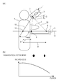
- Fig. 1(a) illustrates the placement of a mammography system of a first embodiment and a testee 4 in a virtual plane including a focal spot center 7, which is the center of the focal spot of an electron beam formed on a target 2, and a normal 10 perpendicular to a target layer 2a.
- an X-ray generating unit 1 includes the target 2 and an electron emitting source 3.
- the X-ray generating unit 1 of the present invention is a transmission X-ray tube.
- the target 2 is a transmission type target in which the target layer 2a that generates X-rays when irradiated with an electron beam is provided on a supporting substrate 2b that transmits X-rays.
- the radiation area of X-rays 18 generated when the target layer 2a is irradiated with an electron beam emitted by the electron emitting source is defined by a collimator (not shown) disposed between the target 2 and a breast 5 of the testee 104, and thus, a predetermined X-ray irradiated area is formed on a detecting portion 17 of an X-ray detecting unit 6 through the breast 105.
- a virtual plane including the detecting portion 17 is hereinafter referred to as a detection plane 11.
- the broken lines indicate a space in which an X-ray beam 18 collimated by the collimator is radiated.
- the X-ray beam 18 radiated from the X-ray generating unit 1 toward the X-ray detecting unit 6 forms an X-ray irradiated area of a predetermined shape on the detecting portion 17.
- Examples of the shape of the X-ray irradiated area include a rectangular shape and a trapezoidal shape.
- the target 2 is disposed such that the target layer 2a faces the electron emitting source 3.
- the X-rays generated when the target layer 2a is irradiated with an electron beam emitted from the electron emitting source 3 are released through the supporting substrate 2b.
- the target layer 2a may be a metal layer with an atomic number of 42 or greater or a layer containing the metal so as to efficiently generate X-rays. Specific examples are tungsten, tantalum, and molybdenum.
- An example of the supporting substrate 2b is a diamond substrate.
- the electron emitting source 3 is an electron gun, which generally includes a cathode, a grid electrode, and a lens electrode (not shown). X-rays can be generated by irradiating the target layer 2a with electrons extracted from the cathode through the grid electrode and then undergoing acceleration and convergence through the lens electrode.
- An example of the cathode is a thermionic cathode.
- the X-ray beam 18 is radiated toward the detection plane 11 of the X-ray detecting unit 6 through the breast 5 of the testee 4 and reaches the detecting portion 17 of the X-ray detecting unit 6.
- An X-ray shadow of the breast 5 of the testee 4 is detected by the X-ray detecting unit 6, and thus, an X-ray radiograph including mammary glands, fat, and so on in the breast 5 is acquired.
- a mammogram can be acquired in this way.
- the X-ray irradiated area is indicated as a line segment defined with a proximal end 8 and a distal end 9, which are at different distances from the testee 4, is formed on the detection plane 11.
- the proximal end 8 is a closest end of an X-ray irradiated region of the detecting portion 17 with regard to a distance from the chest of the testee 4.
- the distal end 9 is a farthest end of an X-ray irradiated region of the detecting portion 17 with regard to a distance from the chest of the testee 4.
- a point of intersection of a normal 10 extending from a focal spot center 7 and the detection plane 11 is defined as a reference point 12.
- the reference point 12 is a point at which the size of an apparent focal spot viewed from the detection plane 11 is the maximum.
- the size of the apparent focal spot on the detection plane 11 decreases with increasing distance from the reference point 12.
- the X-ray mammography system of this embodiment of the present invention is characterized in that the distance A between the reference point 12 and the proximal end 8 and the distance B between the reference point 12 and the distal end 9 have a relationship of distance A ⁇ distance B.
- An angle theta that the normal 10 in the X-ray radiating direction with respect to the detection plane 11 forms with the detection plane 11 opposite to the testee 4 with respect to the reference point 12 is preferably 90 degrees or more and less than 180 degrees.
- the angle theta in this embodiment is 90 degrees.
- Fig. 1(b) quantitatively shows a change in X-ray focal spot diameter and a change in radiation dose between the proximal end 8 and the distal end 9 of the X-ray detecting unit 6 in the case of setting for distance A ⁇ distance B.
- the focal spot diameter decreases with increasing distance from the proximal end 8 to the distal end 9.
- the radiation dose decreases with increasing distance from the proximal end 8 to the distal end 9. Decreasing the focal spot diameter at the distal end 9 to enhance the resolution at a nipple 5a makes it easy to early detect calcification that tends to occur at the nipple 5a.
- the intensity of X-rays radiated from the target 7 depends on the angle of inclination to the normal 10, that is, an exit angle.
- disposing the chest close to the proximal end 8 at which the exit angle with respect to the normal 10 is small can reduce a decrease in detection sensitivity at the chest at which the transmission distance is larger than that at the nipple 5a.
- the distance B is preferably twice or more the distance A to ensure the above advantages.
- the size of the blind area depends on the positional relationship between the focal spot center 7 and the testee 4. To decrease the blind area, the focal spot center 7 needs to be as close as possible to the testee 4.
- the electron emitting source 3 can be disposed at the opposite side from the X-ray radiating direction with respect to the target 2. This can reduce interference of the electron emitting source 3 in setting the focal spot center 7 close to the testee 4, thus making it relatively easy to achieve a configuration in which the distance between the focal spot center 7 and the testee 4 is small.
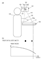
- a second embodiment will next be described with reference to Figs. 2(a) and 2(b).
- the second embodiment is configured to further decrease the blind area described in the first embodiment shown in Fig. 1(a).
- the X-ray generating unit 1 is located above the head of the testee 4 so that the components of the X-ray generating unit 1 around the target 2 are not in contact with the testee 4 even if the planar distance between the focal spot center 7 and the testee 4 is decreased. This can further decrease the planar distance between the focal spot center 7 and the testee 4, thereby reducing the blind area.
- the target 2 is disposed at an angle so that the normal 10 to the surface of the target layer 2a at the focal spot center 7 extended in the X-ray radiating direction is inclined to a direction intersecting the testee 4.
- the angle theta in this case is preferably 100 degrees or more and 160 degrees or less.
- the angle theta in this example is 130 degrees.
- the electron emitting source 3 is disposed at a position far away from the testee 4 with respect to the normal 10 extending toward the electron emitting source 3. Inclining the target 2 in this manner makes it easier to place the focal spot center 7 close to the testee 4 than the first embodiment in which the target 2 is disposed in a horizontal position. Placing the electron emitting source 3 far away from the testee 4 can prevent the electron emitting source 3 from interfering with setting the focal spot center 7 close to the testee 4.
Landscapes
- Health & Medical Sciences (AREA)
- Life Sciences & Earth Sciences (AREA)
- Medical Informatics (AREA)
- Engineering & Computer Science (AREA)
- Optics & Photonics (AREA)
- Biomedical Technology (AREA)
- Biophysics (AREA)
- High Energy & Nuclear Physics (AREA)
- Veterinary Medicine (AREA)
- Nuclear Medicine, Radiotherapy & Molecular Imaging (AREA)
- Public Health (AREA)
- Pathology (AREA)
- Radiology & Medical Imaging (AREA)
- Physics & Mathematics (AREA)
- Heart & Thoracic Surgery (AREA)
- Molecular Biology (AREA)
- Surgery (AREA)
- Animal Behavior & Ethology (AREA)
- General Health & Medical Sciences (AREA)
- Dentistry (AREA)
- Oral & Maxillofacial Surgery (AREA)
- Apparatus For Radiation Diagnosis (AREA)
Priority Applications (1)
| Application Number | Priority Date | Filing Date | Title |
|---|---|---|---|
| US15/022,860 US10070836B2 (en) | 2013-09-19 | 2014-09-10 | X-ray mammography system |
Applications Claiming Priority (2)
| Application Number | Priority Date | Filing Date | Title |
|---|---|---|---|
| JP2013193905A JP6304985B2 (ja) | 2013-09-19 | 2013-09-19 | 放射線撮影装置 |
| JP2013-193905 | 2013-09-19 |
Publications (1)
| Publication Number | Publication Date |
|---|---|
| WO2015040830A1 true WO2015040830A1 (en) | 2015-03-26 |
Family
ID=51842717
Family Applications (1)
| Application Number | Title | Priority Date | Filing Date |
|---|---|---|---|
| PCT/JP2014/004660 Ceased WO2015040830A1 (en) | 2013-09-19 | 2014-09-10 | X-ray mammography system |
Country Status (3)
| Country | Link |
|---|---|
| US (1) | US10070836B2 (enExample) |
| JP (1) | JP6304985B2 (enExample) |
| WO (1) | WO2015040830A1 (enExample) |
Cited By (1)
| Publication number | Priority date | Publication date | Assignee | Title |
|---|---|---|---|---|
| WO2024140924A1 (zh) * | 2022-12-30 | 2024-07-04 | 同方威视技术股份有限公司 | 采用电子直线加速器的货物车辆检查系统 |
Citations (3)
| Publication number | Priority date | Publication date | Assignee | Title |
|---|---|---|---|---|
| JP2007097610A (ja) * | 2005-09-30 | 2007-04-19 | Konica Minolta Medical & Graphic Inc | X線画像撮影システム |
| US20090129549A1 (en) * | 2007-11-21 | 2009-05-21 | Varian Medical Systems Technologies, Inc. | X-ray tube having a focal spot proximate the tube end |
| US20120051496A1 (en) * | 2010-08-25 | 2012-03-01 | Chia-Gee Wang | Thick targets for transmission x-ray tubes |
Family Cites Families (3)
| Publication number | Priority date | Publication date | Assignee | Title |
|---|---|---|---|---|
| JPH01204649A (ja) * | 1988-02-12 | 1989-08-17 | Toshiba Corp | X線撮影装置 |
| JP5294653B2 (ja) * | 2008-02-28 | 2013-09-18 | キヤノン株式会社 | マルチx線発生装置及びx線撮影装置 |
| JP2013504365A (ja) * | 2009-09-15 | 2013-02-07 | コーニンクレッカ フィリップス エレクトロニクス エヌ ヴィ | 分散型x線源及びそれを有するx線イメージングシステム |
-
2013
- 2013-09-19 JP JP2013193905A patent/JP6304985B2/ja active Active
-
2014
- 2014-09-10 US US15/022,860 patent/US10070836B2/en active Active
- 2014-09-10 WO PCT/JP2014/004660 patent/WO2015040830A1/en not_active Ceased
Patent Citations (4)
| Publication number | Priority date | Publication date | Assignee | Title |
|---|---|---|---|---|
| JP2007097610A (ja) * | 2005-09-30 | 2007-04-19 | Konica Minolta Medical & Graphic Inc | X線画像撮影システム |
| US20090129549A1 (en) * | 2007-11-21 | 2009-05-21 | Varian Medical Systems Technologies, Inc. | X-ray tube having a focal spot proximate the tube end |
| JP2011504647A (ja) | 2007-11-21 | 2011-02-10 | バリアン・メディカル・システムズ・インコーポレイテッド | 管端部に近接した焦点位置を有するx線管 |
| US20120051496A1 (en) * | 2010-08-25 | 2012-03-01 | Chia-Gee Wang | Thick targets for transmission x-ray tubes |
Cited By (1)
| Publication number | Priority date | Publication date | Assignee | Title |
|---|---|---|---|---|
| WO2024140924A1 (zh) * | 2022-12-30 | 2024-07-04 | 同方威视技术股份有限公司 | 采用电子直线加速器的货物车辆检查系统 |
Also Published As
| Publication number | Publication date |
|---|---|
| JP6304985B2 (ja) | 2018-04-04 |
| US10070836B2 (en) | 2018-09-11 |
| JP2015058181A (ja) | 2015-03-30 |
| US20160220209A1 (en) | 2016-08-04 |
Similar Documents
| Publication | Publication Date | Title |
|---|---|---|
| US8031834B2 (en) | Tomosynthesis apparatus and method to operate a tomosynthesis apparatus | |
| US9031201B2 (en) | X-ray source, X-ray imaging apparatus, and X-ray computed tomography imaging system | |
| JP6073869B2 (ja) | 複数の焦点スポットx線放射線フィルタリング | |
| US20130156157A1 (en) | X-ray imaging with pixelated detector | |
| CN103943443B (zh) | 具有运动阳极或阴极的x射线源 | |
| JP2015058180A5 (enExample) | ||
| US20160242717A1 (en) | Computed tomographic mammography apparatus | |
| KR20150001181A (ko) | 엑스선 발생기 및 이를 포함한 엑스선 촬영 장치 | |
| JP6346616B2 (ja) | X線位相シフトコントラストイメージング方法およびx線位相シフトコントラストイメージングシステム | |
| EP2818113B1 (en) | X-ray photographing apparatus and method of operating the same | |
| KR20120010639A (ko) | 디지털 x?선 이미징을 위한 단층영상합성 시스템 및 그 제어 방법 | |
| US20240016458A1 (en) | X-ray system and method for operation thereof | |
| US10327718B2 (en) | Dental X-ray imaging device | |
| US20140010348A1 (en) | Radiation generating apparatus and radiation image taking system | |
| US10070836B2 (en) | X-ray mammography system | |
| EP2818112B1 (en) | X-ray photographing apparatus and method of operating the same | |
| US20140126697A1 (en) | Radiation generating apparatus, radiation photographing system, and sighting projector unit included therein | |
| US10039511B2 (en) | Breast tomography system | |
| US10376229B2 (en) | Computed tomographic mammography system | |
| KR20150001179A (ko) | 엑스선 촬영 장치 및 그 동작 방법 | |
| US20150036801A1 (en) | Radiation generating apparatus and radiation imaging system | |
| US20120170715A1 (en) | X-ray tube with a backscattering electron trap | |
| US20230293126A1 (en) | Backscattered x-photon imaging device | |
| JP4777130B2 (ja) | 固定陽極型のx線管における実効焦点を見かけ上小さくする方法 | |
| JP2015058182A5 (ja) | 乳房断層撮影装置 |
Legal Events
| Date | Code | Title | Description |
|---|---|---|---|
| 121 | Ep: the epo has been informed by wipo that ep was designated in this application |
Ref document number: 14790744 Country of ref document: EP Kind code of ref document: A1 |
|
| WWE | Wipo information: entry into national phase |
Ref document number: 15022860 Country of ref document: US |
|
| NENP | Non-entry into the national phase |
Ref country code: DE |
|
| 122 | Ep: pct application non-entry in european phase |
Ref document number: 14790744 Country of ref document: EP Kind code of ref document: A1 |