WO2015040722A1 - 蓄電池システム - Google Patents
蓄電池システム Download PDFInfo
- Publication number
- WO2015040722A1 WO2015040722A1 PCT/JP2013/075343 JP2013075343W WO2015040722A1 WO 2015040722 A1 WO2015040722 A1 WO 2015040722A1 JP 2013075343 W JP2013075343 W JP 2013075343W WO 2015040722 A1 WO2015040722 A1 WO 2015040722A1
- Authority
- WO
- WIPO (PCT)
- Prior art keywords
- storage battery
- power
- sleep control
- charge
- battery system
- Prior art date
- Legal status (The legal status is an assumption and is not a legal conclusion. Google has not performed a legal analysis and makes no representation as to the accuracy of the status listed.)
- Ceased
Links
Images

Classifications
-
- H—ELECTRICITY
- H02—GENERATION; CONVERSION OR DISTRIBUTION OF ELECTRIC POWER
- H02J—ELECTRIC POWER NETWORKS; CIRCUIT ARRANGEMENTS OR SYSTEMS FOR SUPPLYING OR DISTRIBUTING ELECTRIC POWER; SYSTEMS FOR STORING ELECTRIC ENERGY
- H02J3/00—Circuit arrangements for AC mains or AC distribution networks
- H02J3/28—Arrangements for balancing of the load in networks by storage of energy
- H02J3/32—Arrangements for balancing of the load in networks by storage of energy using batteries or super capacitors with converting means
-
- H—ELECTRICITY
- H02—GENERATION; CONVERSION OR DISTRIBUTION OF ELECTRIC POWER
- H02J—ELECTRIC POWER NETWORKS; CIRCUIT ARRANGEMENTS OR SYSTEMS FOR SUPPLYING OR DISTRIBUTING ELECTRIC POWER; SYSTEMS FOR STORING ELECTRIC ENERGY
- H02J4/00—Circuit arrangements for mains or distribution networks not specified as AC or DC; Circuit arrangements for mains or distribution networks combining AC and DC sections or sub-networks
- H02J4/20—Networks integrating separated AC and DC power sections
- H02J4/25—Networks integrating separated AC and DC power sections for transfer of electric power between AC and DC networks, e.g. for supplying the DC section within a load from an AC mains system
-
- H—ELECTRICITY
- H02—GENERATION; CONVERSION OR DISTRIBUTION OF ELECTRIC POWER
- H02J—ELECTRIC POWER NETWORKS; CIRCUIT ARRANGEMENTS OR SYSTEMS FOR SUPPLYING OR DISTRIBUTING ELECTRIC POWER; SYSTEMS FOR STORING ELECTRIC ENERGY
- H02J7/00—Circuit arrangements for charging or discharging batteries or for supplying loads from batteries
- H02J7/02—Circuit arrangements for charging or discharging batteries or for supplying loads from batteries for charging batteries from AC mains by converters
-
- H—ELECTRICITY
- H02—GENERATION; CONVERSION OR DISTRIBUTION OF ELECTRIC POWER
- H02J—ELECTRIC POWER NETWORKS; CIRCUIT ARRANGEMENTS OR SYSTEMS FOR SUPPLYING OR DISTRIBUTING ELECTRIC POWER; SYSTEMS FOR STORING ELECTRIC ENERGY
- H02J7/00—Circuit arrangements for charging or discharging batteries or for supplying loads from batteries
- H02J7/50—Circuit arrangements for charging or discharging batteries or for supplying loads from batteries acting upon multiple batteries simultaneously or sequentially
-
- H—ELECTRICITY
- H02—GENERATION; CONVERSION OR DISTRIBUTION OF ELECTRIC POWER
- H02J—ELECTRIC POWER NETWORKS; CIRCUIT ARRANGEMENTS OR SYSTEMS FOR SUPPLYING OR DISTRIBUTING ELECTRIC POWER; SYSTEMS FOR STORING ELECTRIC ENERGY
- H02J7/00—Circuit arrangements for charging or discharging batteries or for supplying loads from batteries
- H02J7/80—Circuit arrangements for charging or discharging batteries or for supplying loads from batteries including monitoring or indicating arrangements
- H02J7/82—Control of state of charge [SOC]
Definitions
- FIG. 9 of Patent Document 1 shows an example of a storage battery system connected to an electric power system.
- the charge / discharge request supplied from the EMS to the PCS is determined so as to balance power supply and demand in the entire power system, but is not necessarily appropriate for the storage battery. Since the amount of calculations performed by the EMS is enormous, it is difficult for the EMS to grasp the state of the storage battery that is the recipient of the request one by one and to perform fine control according to it. In particular, when the storage battery system has a large capacity, the storage battery is composed of an extremely large number of cells, specifically, hundreds to tens of thousands of cells. Is extremely difficult.
- the life of a storage battery changes depending on the holding voltage.
- sleep control for maintaining the voltage of the storage battery within an appropriate holding voltage range while the storage battery is not used is known.
- the EMS manages the sleep control it is difficult to grasp the state of all the cells one by one as described above and perform fine control. Therefore, the control is performed based on the voltage of the entire storage battery.
- the present invention has been made in view of the above-described problems, and an object thereof is to provide a storage battery system capable of suppressing cell deterioration in a storage battery including a plurality of cells.
- the storage battery system according to the present invention is configured as follows.
- the storage battery system includes a storage battery, a storage battery monitoring device, an AC / DC conversion device, and a control device.
- the storage battery is configured as an assembly of a plurality of cells.
- a large-capacity storage battery such as a lithium ion battery, a sodium sulfur battery, or a nickel metal hydride battery is preferable.
- the storage battery monitoring device is a device that monitors the state of the storage battery constantly or at a predetermined cycle. Examples of monitoring items by the storage battery monitoring device include state quantities such as current, voltage, and temperature. In terms of voltage, the voltage is monitored individually for each cell.
- the storage battery monitoring device measures a state quantity, which is a monitoring item, at all times or at a predetermined cycle by a sensor, and outputs part or all of the obtained data to the outside as storage battery information.
- the control device is a device interposed between the energy management system and the AC / DC converter.
- the control device receives a charge / discharge request supplied from the energy management system to the storage battery system.
- the control device is configured to receive the storage battery information supplied from the storage battery monitoring device together with the charge / discharge request, and to control the AC / DC converter based on the charge / discharge request and the storage battery information.
- the control device includes a sleep control unit.
- the sleep control unit receives the storage battery information, and executes sleep control that outputs a charge / discharge command to the AC / DC converter so as to keep the average voltage of each cell within a holding voltage range that suppresses deterioration of the storage battery.
- the holding voltage is a voltage at which deterioration of the storage battery can be most suppressed, and is different for each type of storage battery.
- the holding voltage range is a range suitable for suppressing deterioration of the storage battery centered on this holding voltage, and is set in advance.
- the sleep control unit outputs a charge / discharge command to the AC / DC converter so as to keep the average voltage of the plurality of cells included in the storage battery information within a holding voltage range that suppresses deterioration of the storage battery. Further, the sleep control unit includes a sleep control stop function for stopping sleep control when the voltage of any of the plurality of cells included in the storage battery information is outside the allowable voltage range including the holding voltage range.
- the upper limit value of the allowable voltage range is set smaller than an interlock threshold value at which the storage battery is determined to be overcharged, and the lower limit value of the allowable voltage range is set to be higher than an interlock threshold value at which the storage battery is determined to be overdischarged. .
- the sleep control unit is configured to store in advance a schedule for the storage battery system to be used in the power system, and execute sleep control according to the schedule.
- the schedule can be created in advance based on the past power supply / demand history of the power system. For example, the schedule is planned to execute sleep control in a time zone in which the power demand of the load facility and the power supply of the power generation facility are balanced.
- the schedule defines a peak cut period in which the storage battery system is used for peak cut of the power system and a preparation period before this peak cut period.
- the sleep control unit includes a peak cut preparation function that ends the sleep control and increases the voltage of the storage battery during the preparation period. Note that the peak cut period and the preparation period are not included in the time period in which the sleep control described above is executed.
- control device further includes an interlock processing unit.
- An interlock process part is comprised so that when the abnormality of a storage battery system is detected, the interlock process according to the content of the detected abnormality is performed.
- Abnormalities in the storage battery system can be detected from storage battery information supplied from the storage battery monitoring device, for example. In detecting an abnormality in the storage battery system, it is of course possible to refer to information other than the storage battery information, for example, information from the AC / DC converter.
- the sleep control is stopped when the voltage of any cell is outside the allowable voltage range during the sleep control for the storage battery including a plurality of cells. For this reason, according to the storage battery system which concerns on this invention, deterioration of a cell can be suppressed. Further, before the cell voltage becomes an abnormal voltage, charging / discharging can be stopped to prevent a serious failure of the storage battery.
- Embodiment 1 is a block diagram of a system according to Embodiment 1 of the present invention. It is a figure for demonstrating an example of the schedule which a storage battery system uses in Embodiment 1 of this invention. It is a flowchart of the control routine which a storage battery system performs in order to implement
- FIG. 1 is a conceptual configuration diagram for explaining a system configuration according to Embodiment 1 of the present invention.
- a storage battery system 10 shown in FIG. 1 is connected to a power transmission facility 20 of a power system.
- the power system includes power transmission equipment 20, power generation equipment (not shown) connected to the power transmission equipment 20, and load equipment (not shown) connected to the power transmission equipment 20.
- the storage battery system 10 is connected to a remote energy management system (hereinafter referred to as EMS) 30 by a computer network 40.
- the EMS 30 manages the power supply and demand of the power system such as the power generation amount of the power generation facility, the charge / discharge amount of the storage battery system 10, and the power reception amount of the load facility.
- the storage battery system 10 includes an AC / DC converter (hereinafter referred to as PCS) 100, a front battery control station panel (hereinafter referred to as FBCS panel) 120, and a storage battery panel 140.
- PCS AC / DC converter
- FBCS panel front battery control station panel
- storage battery panel 140 storage battery panel 140
- one FBCS panel 120 is connected to one PCS 100
- a plurality of storage battery panels 140 are connected in parallel to one FBCS panel 120.
- the storage battery panel 140 has three rows, but this is merely an example.
- the number of parallel storage battery panels 140 is determined based on the specifications of the PCS 100. Therefore, the parallel number of the storage battery panels 140 may be one row.
- the storage battery system 10 includes one PCS 100, but this is merely an example.
- the number of parallel PCSs 100 is determined based on the specifications of the storage battery system 10. Therefore, the parallel number of PCS100 may become plural.
- the storage battery panel 140 includes a fuse 141, a contactor 142, a storage battery module 143, and a storage battery monitoring device (hereinafter referred to as BMU: Battery Management Unit) 144.
- the storage battery module 143 is a module in which a plurality of cells are connected in series. Each cell is a lithium ion battery (LiB).
- the storage battery module 143 is connected to the FBCS panel 120 by a power transmission line via the contactor 142 and the fuse 141.
- the storage battery module 143 is connected to the BMU 144 by a signal line.
- the BMU 144 is connected to the control device 130 on the FBCS board 120 via the computer network 50 and is connected to the contactor 142 via a signal line.
- the BMU 144 monitors the state of the storage battery module 143.
- the BMU 144 includes a current sensor (not shown), a voltage sensor (not shown), and a temperature sensor (not shown) as means for measuring the state quantity of the storage battery module 143.
- the current flowing through the storage battery module 143 is measured by the current sensor.
- the voltage of each cell is measured by a voltage sensor provided for each cell.
- the temperature of the storage battery module 143 is measured by the temperature sensor.
- These sensors do not necessarily have to be in the BMU 144 housing. It is also possible to adopt a configuration in which these sensors attached to the storage battery module 143 and the BMU 144 are connected by a signal line. Moreover, monitoring of the storage battery module 143 by BMU144 is always performed.
- the constant monitoring in the present embodiment is a concept including not only an operation of capturing a continuous signal from a sensor but also an operation of capturing a sensor signal at a predetermined short cycle.
- the BMU 144 transmits storage battery information including information obtained by measurement by each sensor to the control device 130.
- the FBCS panel 120 is connected to the storage battery panel 140 and the PCS 100. Specifically, each storage battery panel 140 is connected to the FBCS panel 120 by an individual power transmission line. The individual transmission lines merge inside the FBCS panel and are connected to a thicker transmission line. The merged power transmission line is connected to the PCS 100.
- the FBCS board 120 includes a control device 130.
- the control device 130 includes, for example, a memory including a ROM and a RAM, an input / output interface that inputs and outputs various types of information, and a processor that can execute various types of arithmetic processing based on the various types of information.
- the control device 130 is connected to the EMS 30 via the computer network 40, to the BMU 144 via the computer network 50, and to the PCS 100 via the computer network 60.
- the control device 130 is connected to the contactor 142 by a signal line.
- the PCS 100 is connected to the power transmission facility 20 by a power transmission line via a transformer.
- the PCS 100 includes a charging function that converts AC power of the power system into DC power and charges the storage battery module 143, and a discharging function that converts DC power of the storage battery module 143 into AC power and discharges it to the power system.
- the amount of electric power charged into the storage battery module 143 and the amount of electric power discharged from the storage battery module 143 are adjusted by the PCS 100.
- the adjustment of the charge / discharge power amount by the PCS 100 is performed according to a charge / discharge instruction supplied from the control device 130.
- the PCS 100 includes a current sensor (not shown) and a voltage sensor (not shown), and the PCS 100 refers to output values of these sensors to adjust the charge / discharge power amount.
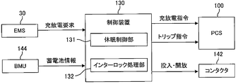
- FIG. 2 is a block diagram of a system according to Embodiment 1 of the present invention.
- the block which shows the control apparatus 130 in FIG. 2, some of the various functions with which the control apparatus 130 is provided is represented by the block. Computing resources are allocated to each of these blocks.
- a program corresponding to each block is prepared in the control device 130, and the function of each block is realized in the control device 130 by executing them by a processor.
- the control device 130 receives a charge / discharge request from the EMS 30 and receives storage battery information from the BMU 144. Control device 130 determines a charge / discharge command based on the charge / discharge request and storage battery information, and transmits the charge / discharge command to PCS 100.
- the sleep control unit 131 stops sleep control when the voltage of any cell of the storage battery module 143 is outside the allowable voltage range.
- the allowable voltage range includes the holding voltage range. Therefore, the upper limit value of the allowable voltage range is set higher than the upper limit value of the holding voltage range, and the lower limit value of the allowable voltage range is set lower than the lower limit value of the holding voltage range.
- the control device 130 has a sleep control schedule function, and the sleep control unit 131 takes charge of the function.
- the sleep control unit 131 stores in advance a schedule for the storage battery system 10 to be used for the power system, and executes sleep control according to the schedule.
- the schedule can be created in advance based on the past power supply / demand history of the power system.
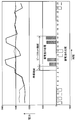
- the schedule includes a peak cut period, a peak cut preparation period, and a sleep control period.
- FIG. 3 is a diagram for explaining an example of a schedule used by the storage battery system in the first embodiment of the present invention.
- the peak cut period is a time zone in which the storage battery system 10 is used for peak cut of the power system.
- the peak cut period is a time zone from 10:00 to 17:00.
- the peak cut preparation period is a preparation period for increasing the voltage in preparation for power supply in the next peak cut period.
- the peak cut preparation period is a time zone from 9:00 to 10:00.
- the sleep control unit 131 executes sleep control during the sleep control period.
- the sleep control unit includes a peak cut preparation function that ends the sleep control during the peak cut preparation period and increases the voltage of the storage battery.
- the control device 130 has an interlock function, and the interlock processing unit 132 takes charge of the function. Interlocking of the storage battery module 143 is also performed by the BMU 144 when the BMU 144 detects overdischarge, overcharge, temperature abnormality, or the like. However, when these abnormalities occur, the storage battery is already in a considerably overloaded state. Therefore, in the system of the present embodiment, the PCS 100 and the contactor 142 are controlled by software interlock before the interlock by the BMU 144 is executed. When detecting an abnormality in the storage battery system 10, the interlock processing unit 132 performs an interlock process according to the content of the detected abnormality.
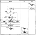
- FIG. 4 is a flowchart of a control routine executed by the storage battery system 10 in order to realize the sleep control stop function in the first embodiment of the present invention.
- the process of the control device 130 shown in this flowchart is a process realized by the function of the sleep control unit 131.
- a program for executing the processing of the flowchart shown in FIG. 4 is stored in the memory of the control device 130, and the processing shown in FIG. 4 is realized by the processor of the control device 130 reading and executing the program.
- the sleep control is being executed in another routine.
- the details of the sleep control are as described in the description of the sleep control function.
- step S203 when the cell voltage is equal to or higher than the lower limit value, since the cell voltage is within the allowable voltage range, it is determined to continue the sleep control (step S205).
- the control device determines a charge / discharge command for sleep control (step S207).
- Control device 130 transmits the determined charge / discharge command to PCS 100 (step S208).
- the PCS 100 receives the charge / discharge command transmitted from the control device 130 (step S301).
- the PCS 100 performs a charge / discharge operation in accordance with the charge / discharge command (step S302).
- the storage battery system 10 provides a peak cut preparation period between the sleep control period and the peak cut period, thereby suppressing deterioration of the storage battery by sleep control until the peak cut preparation period. be able to. Moreover, it can prepare for a peak cut period by providing a peak cut preparation period.
Landscapes
- Engineering & Computer Science (AREA)
- Power Engineering (AREA)
- Charge And Discharge Circuits For Batteries Or The Like (AREA)
- Supply And Distribution Of Alternating Current (AREA)
- Protection Of Static Devices (AREA)
- Remote Monitoring And Control Of Power-Distribution Networks (AREA)
Abstract
Description
[実施の形態1の全体構成]
図1は、本発明の実施の形態1に係るシステム構成を説明するための概念構成図である。図1に示す蓄電池システム10は、電力系統の送電設備20に接続される。電力系統には、送電設備20の他、送電設備20に接続された発電設備(図示省略)、送電設備20に接続された負荷設備(図示省略)が含まれる。蓄電池システム10は、コンピュータネットワーク40により遠方のエネルギマネジメントシステム(以下、EMS)30に接続される。EMS30は、発電設備の発電量、蓄電池システム10の充放電量、負荷設備の受電量など、電力系統の電力需給を管理する。
蓄電池盤140は、ヒューズ141、コンタクタ142、蓄電池モジュール143、及び蓄電池監視装置(以下、BMU:Battery Management Unit)144を備える。蓄電池モジュール143は、複数のセルが直列に接続されたモジュールである。各セルは、リチウムイオン電池(LiB)である。蓄電池モジュール143は、コンタクタ142及びヒューズ141を介して送電線によりFBCS盤120に接続される。また、蓄電池モジュール143は、信号線によりBMU144に接続される。BMU144は、コンピュータネットワーク50によりFBCS盤120上の制御装置130に接続され、信号線によりコンタクタ142に接続される。
FBCS盤120は、蓄電池盤140とPCS100とに接続される。具体的には、各蓄電池盤140は、個別の送電線によりFBCS盤120に接続される。個別の送電線はFBCS盤の内部で合流し、より太い送電線に接続される。合流後の送電線はPCS100に接続される。また、FBCS盤120は制御装置130を備える。制御装置130は、例えばROM、RAM等を含むメモリ、各種情報を入出力する入出力インタフェース、各種情報に基づいて各種演算処理を実行可能なプロセッサを備える。制御装置130は、コンピュータネットワーク40によりEMS30に、コンピュータネットワーク50によりBMU144に、コンピュータネットワーク60によりPCS100に接続される。また、制御装置130は、信号線によりコンタクタ142に接続される。
PCS100は、変圧器を介して送電線により送電設備20に接続される。PCS100は、電力系統の交流電力を直流電力に変換して蓄電池モジュール143に充電する充電機能と、蓄電池モジュール143の直流電力を交流電力に変換して電力系統に放電する放電機能とを備える。蓄電池モジュール143への充電電力量、及び蓄電池モジュール143からの放電電力量は、PCS100によって調整される。PCS100による充放電電力量の調整は、制御装置130から供給される充放電指示に従って行われる。PCS100は電流センサ(図示省略)と電圧センサ(図示省略)とを備え、PCS100はこれらのセンサの出力値を参照して充放電電力量の調整を実施する。
図2は、本発明の実施の形態1に係るシステムのブロック図である。図2における制御装置130を示すブロック内には、制御装置130が備える種々の機能のうちの一部がブロックで表されている。これらブロックのそれぞれに演算資源が割り当てられている。制御装置130には各ブロックに対応するプログラムが用意され、それらがプロセッサによって実行されることで各ブロックの機能が制御装置130において実現される。
制御装置130は休眠制御機能を有し、その機能は休眠制御部131が受け持つ。休眠制御部131は、充放電をしばらく行わない場合に、蓄電池モジュール143の放置劣化を抑制するために、セル電圧を所定の保持電圧範囲に保つ休眠モード運転を実行する。例えば、休眠制御部131は、EMS30から、あるいはFBCS盤に接続された操作装置から休眠モード運転指令がなされた場合に休眠制御を実行する。保持電圧範囲は、例えば3.8[V]±数百[mV]とする。
加えて、制御装置130は休眠制御停止機能を有し、その機能は休眠制御部131が受け持つ。特定のセルに異常があった場合、セル平均電圧は保持電圧範囲内であるが、当該セルの電圧は、保持電圧範囲を超えて高く又は低くなるおそれがある。このような場合に休眠制御を継続すれば、蓄電池モジュール143の劣化を抑制できないばかりか、当該セルの劣化を早めるおそれがある。
制御装置130は休眠制御スケジュール機能を有し、その機能は休眠制御部131が受け持つ。休眠制御部131は、蓄電池システム10が電力系統に利用されるスケジュールを予め記憶し、このスケジュールに従って休眠制御を実行する。スケジュールは、電力系統の過去の電力需給履歴に基づいて予め作成できる。
また、制御装置130はインターロック機能を有し、その機能はインターロック処理部132が受け持つ。蓄電池モジュール143のインターロックは、BMU144が過放電、過充電、温度異常等を検出した場合に、BMU144によっても行われる。しかし、これらの異常が発生したときには、蓄電池は既にかなりの過負荷状態になっている。そこで、本実施の形態のシステムでは、BMU144によるインターロックが実行される前に、ソフトウェアインターロックによりPCS100、コンタクタ142を制御する。インターロック処理部132は、蓄電池システム10の異常を検知した場合に、検知した異常の内容に応じたインターロック処理を施す。具体的には、インターロック処理は、PCS100へトリップ信号を出力する処理や、コンタクタ142を開放させる処理である。なお、BMU144に先駆けてインターロック処理を実行するために、電流、電圧、温度等のインターロック閾値は、BMU144に設定された閾値よりも低く設定されている。
図4は、本発明の実施の形態1における休眠制御停止機能を実現するために、蓄電池システム10が実行する制御ルーチンのフローチャートである。このフローチャートに示す制御装置130の処理は、休眠制御部131の機能によって実現される処理である。制御装置130のメモリには、図4に示すフローチャートの処理を実行するプログラムが記憶されており、制御装置130のプロセッサがプログラムを読み出して、実行することにより図4に示す処理が実現される。
20 送電設備
30 エネルギマネジメントシステム(EMS)
40,50,60 コンピュータネットワーク
100 交直変換装置(PCS)
120 FBCS盤
130 制御装置
131 休眠制御部
132 インターロック処理部
140 蓄電池盤
141 ヒューズ
142 コンタクタ
143 蓄電池モジュール
144 蓄電池監視装置(BMU)
Claims (5)
- 電力系統に接続される蓄電池システムであって、前記電力系統の電力需給を管理するエネルギマネジメントシステムからの充放電要求に基づいて動作する蓄電池システムにおいて、
複数のセルが直列に接続されてなる蓄電池と、
前記蓄電池の状態を常時監視する蓄電池監視装置と、
前記電力系統の交流電力を直流電力に変換して前記蓄電池に充電する機能と、前記蓄電池の直流電力を交流電力に変換して前記電力系統に放電する機能とを有する交直変換装置と、
前記充放電要求と、前記蓄電池監視装置から供給される蓄電池情報とを受信し、前記充放電要求と前記蓄電池情報とに基づいて前記交直変換装置を制御する制御装置と、を備え、
前記制御装置は、
前記蓄電池情報を受信し、前記複数のセルの平均電圧を前記蓄電池の劣化を抑制する保持電圧範囲内に保つように前記交直変換装置に対して充放電指令を出力する休眠制御を実行する休眠制御部を備え、
前記休眠制御部は、前記蓄電池情報に含まれる前記複数のセルのいずれかの電圧が、前記保持電圧範囲を内包する許容電圧範囲外にある場合に、前記休眠制御を停止させる休眠制御停止機能を備える
ことを特徴とする蓄電池システム。 - 前記制御装置は、前記蓄電池システムの異常を検知した場合に、検知した異常の内容に応じたインターロック処理を施すインターロック処理部をさらに備える
ことを特徴とする請求項1に記載の蓄電池システム。 - 前記インターロック処理部は、前記蓄電池情報から前記蓄電池システムの異常を検知するように構成されている
ことを特徴とする請求項2に記載の蓄電池システム。 - 前記休眠制御部は、前記蓄電池システムが前記電力系統に利用されるスケジュールを予め記憶し、前記スケジュールに従って前記休眠制御を実行する
ことを特徴とする請求項1乃至3のいずれか1項に記載の蓄電池システム。 - 前記スケジュールには、前記蓄電池システムが前記電力系統のピークカットに利用されるピークカット期間と、前記ピークカット期間前の準備期間が定められ、
前記休眠制御部は、前記準備期間において、前記休眠制御を終了させて前記蓄電池の電圧を高めるピークカット準備機能をさらに備える
ことを特徴とする請求項1乃至4のいずれか1項に記載の蓄電池システム。
Priority Applications (4)
| Application Number | Priority Date | Filing Date | Title |
|---|---|---|---|
| CN201380079690.8A CN105556785B (zh) | 2013-09-19 | 2013-09-19 | 蓄电池系统 |
| US14/914,039 US10014698B2 (en) | 2013-09-19 | 2013-09-19 | Storage battery system |
| PCT/JP2013/075343 WO2015040722A1 (ja) | 2013-09-19 | 2013-09-19 | 蓄電池システム |
| JP2015537508A JP6288096B2 (ja) | 2013-09-19 | 2013-09-19 | 蓄電池システム |
Applications Claiming Priority (1)
| Application Number | Priority Date | Filing Date | Title |
|---|---|---|---|
| PCT/JP2013/075343 WO2015040722A1 (ja) | 2013-09-19 | 2013-09-19 | 蓄電池システム |
Publications (1)
| Publication Number | Publication Date |
|---|---|
| WO2015040722A1 true WO2015040722A1 (ja) | 2015-03-26 |
Family
ID=52688404
Family Applications (1)
| Application Number | Title | Priority Date | Filing Date |
|---|---|---|---|
| PCT/JP2013/075343 Ceased WO2015040722A1 (ja) | 2013-09-19 | 2013-09-19 | 蓄電池システム |
Country Status (4)
| Country | Link |
|---|---|
| US (1) | US10014698B2 (ja) |
| JP (1) | JP6288096B2 (ja) |
| CN (1) | CN105556785B (ja) |
| WO (1) | WO2015040722A1 (ja) |
Cited By (2)
| Publication number | Priority date | Publication date | Assignee | Title |
|---|---|---|---|---|
| WO2019231047A1 (ko) * | 2018-06-01 | 2019-12-05 | 엘지이노텍 주식회사 | 태양광 연계 에너지 저장 시스템용 dc-dc 컨버터 및 그 제어방법 |
| JPWO2022004753A1 (ja) * | 2020-06-30 | 2022-01-06 |
Families Citing this family (3)
| Publication number | Priority date | Publication date | Assignee | Title |
|---|---|---|---|---|
| JP6384483B2 (ja) * | 2013-09-19 | 2018-09-05 | 東芝三菱電機産業システム株式会社 | 蓄電池システム |
| CN108899975A (zh) * | 2018-08-10 | 2018-11-27 | 肇庆市高新区甜慕新能源技术有限公司 | 一种蓄电池系统 |
| CN112285478B (zh) * | 2020-11-25 | 2024-03-19 | 北京车和家信息技术有限公司 | 车辆静态电流的检测方法和装置、介质、设备、车辆 |
Citations (3)
| Publication number | Priority date | Publication date | Assignee | Title |
|---|---|---|---|---|
| JP2000195558A (ja) * | 1998-12-28 | 2000-07-14 | Toyota Central Res & Dev Lab Inc | 非水電解液二次電池の充放電制御装置 |
| WO2009084673A1 (ja) * | 2007-12-28 | 2009-07-09 | Sumitomo Heavy Industries, Ltd. | ハイブリッド式建設機械 |
| JP2013169068A (ja) * | 2012-02-15 | 2013-08-29 | Sanyo Electric Co Ltd | 電力制御システム |
Family Cites Families (10)
| Publication number | Priority date | Publication date | Assignee | Title |
|---|---|---|---|---|
| CN101714647B (zh) * | 2008-10-08 | 2012-11-28 | 株式会社牧田 | 电动工具用蓄电池匣以及电动工具 |
| US20120286739A1 (en) * | 2009-12-11 | 2012-11-15 | A123 Systems, Inc. | System and Method for Estimating a State of a Battery Pack |
| JP5271329B2 (ja) | 2010-09-28 | 2013-08-21 | 株式会社東芝 | 蓄電池管理システム |
| JP2012175864A (ja) | 2011-02-23 | 2012-09-10 | Sanyo Electric Co Ltd | 蓄電システム |
| JP5677161B2 (ja) * | 2011-03-28 | 2015-02-25 | 株式会社東芝 | 充放電判定装置及びプログラム |
| JP5877360B2 (ja) * | 2011-05-26 | 2016-03-08 | パナソニックIpマネジメント株式会社 | 蓄電池制御システム |
| JP5802463B2 (ja) | 2011-07-22 | 2015-10-28 | 株式会社東芝 | 電気量調整装置、電気量調整方法、電気量調整プログラム及び電力供給システム |
| JP2013207901A (ja) * | 2012-03-28 | 2013-10-07 | Sanyo Electric Co Ltd | 電池制御装置 |
| KR101477272B1 (ko) * | 2012-11-09 | 2015-01-06 | 주식회사 엘지화학 | 이차 전지 셀의 충전량 밸런싱 작업을 제어하는 장치 및 방법 |
| US9559536B2 (en) * | 2014-04-30 | 2017-01-31 | Johnson Controls Technology Company | State of charge indicator method and system |
-
2013
- 2013-09-19 US US14/914,039 patent/US10014698B2/en active Active
- 2013-09-19 CN CN201380079690.8A patent/CN105556785B/zh active Active
- 2013-09-19 WO PCT/JP2013/075343 patent/WO2015040722A1/ja not_active Ceased
- 2013-09-19 JP JP2015537508A patent/JP6288096B2/ja active Active
Patent Citations (3)
| Publication number | Priority date | Publication date | Assignee | Title |
|---|---|---|---|---|
| JP2000195558A (ja) * | 1998-12-28 | 2000-07-14 | Toyota Central Res & Dev Lab Inc | 非水電解液二次電池の充放電制御装置 |
| WO2009084673A1 (ja) * | 2007-12-28 | 2009-07-09 | Sumitomo Heavy Industries, Ltd. | ハイブリッド式建設機械 |
| JP2013169068A (ja) * | 2012-02-15 | 2013-08-29 | Sanyo Electric Co Ltd | 電力制御システム |
Cited By (5)
| Publication number | Priority date | Publication date | Assignee | Title |
|---|---|---|---|---|
| WO2019231047A1 (ko) * | 2018-06-01 | 2019-12-05 | 엘지이노텍 주식회사 | 태양광 연계 에너지 저장 시스템용 dc-dc 컨버터 및 그 제어방법 |
| US11936337B2 (en) | 2018-06-01 | 2024-03-19 | Lg Innotek Co., Ltd. | DC-DC converter for solar-related energy storage system, and control method thereof |
| JPWO2022004753A1 (ja) * | 2020-06-30 | 2022-01-06 | ||
| WO2022004753A1 (ja) * | 2020-06-30 | 2022-01-06 | 本田技研工業株式会社 | 台座、蓄電装置組立体、蓄電装置収容システム、蓄電装置管理システム、蓄電装置管理方法、プログラム及びコンピュータ可読記録媒体 |
| JP7759321B2 (ja) | 2020-06-30 | 2025-10-23 | 本田技研工業株式会社 | 台座、蓄電装置組立体、蓄電装置収容システム、蓄電装置管理システム、蓄電装置管理方法、プログラム及びコンピュータ可読記録媒体 |
Also Published As
| Publication number | Publication date |
|---|---|
| US10014698B2 (en) | 2018-07-03 |
| CN105556785B (zh) | 2018-05-11 |
| JPWO2015040722A1 (ja) | 2017-03-02 |
| US20160211678A1 (en) | 2016-07-21 |
| JP6288096B2 (ja) | 2018-03-07 |
| CN105556785A (zh) | 2016-05-04 |
Similar Documents
| Publication | Publication Date | Title |
|---|---|---|
| CN105556782B (zh) | 蓄电池系统 | |
| JP6384483B2 (ja) | 蓄電池システム | |
| US8396609B2 (en) | Control of cells, modules and a pack comprised of hybridized electrochemistries | |
| JP5896096B1 (ja) | 発電設備および発電制御装置 | |
| KR101097264B1 (ko) | 센싱보드가 내장된 배터리팩과 그것을 채용한 전력저장시스템 | |
| KR102415123B1 (ko) | 배터리 팩 및 이를 포함하는 에너지 저장 시스템 | |
| JP6249022B2 (ja) | 蓄電池システム | |
| KR20140128468A (ko) | 배터리 밸런싱 장치 및 방법 | |
| JP6288096B2 (ja) | 蓄電池システム | |
| WO2015040723A1 (ja) | 蓄電池システム | |
| US20170256945A1 (en) | Storage battery system | |
| KR102061308B1 (ko) | 배터리 관리를 위한 제어전원 공급시스템과 그 공급방법 및 이를 이용한 에너지저장시스템 | |
| US10224724B2 (en) | Charge/discharge management device | |
| US10145902B2 (en) | Storage battery capacity measurement device | |
| CN112952928A (zh) | 蓄电池系统 |
Legal Events
| Date | Code | Title | Description |
|---|---|---|---|
| WWE | Wipo information: entry into national phase |
Ref document number: 201380079690.8 Country of ref document: CN |
|
| 121 | Ep: the epo has been informed by wipo that ep was designated in this application |
Ref document number: 13894054 Country of ref document: EP Kind code of ref document: A1 |
|
| ENP | Entry into the national phase |
Ref document number: 2015537508 Country of ref document: JP Kind code of ref document: A |
|
| WWE | Wipo information: entry into national phase |
Ref document number: 14914039 Country of ref document: US |
|
| NENP | Non-entry into the national phase |
Ref country code: DE |
|
| 122 | Ep: pct application non-entry in european phase |
Ref document number: 13894054 Country of ref document: EP Kind code of ref document: A1 |