WO2015033713A1 - 成膜装置 - Google Patents
成膜装置 Download PDFInfo
- Publication number
- WO2015033713A1 WO2015033713A1 PCT/JP2014/070328 JP2014070328W WO2015033713A1 WO 2015033713 A1 WO2015033713 A1 WO 2015033713A1 JP 2014070328 W JP2014070328 W JP 2014070328W WO 2015033713 A1 WO2015033713 A1 WO 2015033713A1
- Authority
- WO
- WIPO (PCT)
- Prior art keywords
- film forming
- unit
- forming material
- film
- material supply
- Prior art date
- Legal status (The legal status is an assumption and is not a legal conclusion. Google has not performed a legal analysis and makes no representation as to the accuracy of the status listed.)
- Ceased
Links
Images



Classifications
-
- C—CHEMISTRY; METALLURGY
- C23—COATING METALLIC MATERIAL; COATING MATERIAL WITH METALLIC MATERIAL; CHEMICAL SURFACE TREATMENT; DIFFUSION TREATMENT OF METALLIC MATERIAL; COATING BY VACUUM EVAPORATION, BY SPUTTERING, BY ION IMPLANTATION OR BY CHEMICAL VAPOUR DEPOSITION, IN GENERAL; INHIBITING CORROSION OF METALLIC MATERIAL OR INCRUSTATION IN GENERAL
- C23C—COATING METALLIC MATERIAL; COATING MATERIAL WITH METALLIC MATERIAL; SURFACE TREATMENT OF METALLIC MATERIAL BY DIFFUSION INTO THE SURFACE, BY CHEMICAL CONVERSION OR SUBSTITUTION; COATING BY VACUUM EVAPORATION, BY SPUTTERING, BY ION IMPLANTATION OR BY CHEMICAL VAPOUR DEPOSITION, IN GENERAL
- C23C14/00—Coating by vacuum evaporation, by sputtering or by ion implantation of the coating forming material
- C23C14/22—Coating by vacuum evaporation, by sputtering or by ion implantation of the coating forming material characterised by the process of coating
- C23C14/24—Vacuum evaporation
- C23C14/28—Vacuum evaporation by wave energy or particle radiation
- C23C14/30—Vacuum evaporation by wave energy or particle radiation by electron bombardment
-
- C—CHEMISTRY; METALLURGY
- C23—COATING METALLIC MATERIAL; COATING MATERIAL WITH METALLIC MATERIAL; CHEMICAL SURFACE TREATMENT; DIFFUSION TREATMENT OF METALLIC MATERIAL; COATING BY VACUUM EVAPORATION, BY SPUTTERING, BY ION IMPLANTATION OR BY CHEMICAL VAPOUR DEPOSITION, IN GENERAL; INHIBITING CORROSION OF METALLIC MATERIAL OR INCRUSTATION IN GENERAL
- C23C—COATING METALLIC MATERIAL; COATING MATERIAL WITH METALLIC MATERIAL; SURFACE TREATMENT OF METALLIC MATERIAL BY DIFFUSION INTO THE SURFACE, BY CHEMICAL CONVERSION OR SUBSTITUTION; COATING BY VACUUM EVAPORATION, BY SPUTTERING, BY ION IMPLANTATION OR BY CHEMICAL VAPOUR DEPOSITION, IN GENERAL
- C23C14/00—Coating by vacuum evaporation, by sputtering or by ion implantation of the coating forming material
- C23C14/22—Coating by vacuum evaporation, by sputtering or by ion implantation of the coating forming material characterised by the process of coating
- C23C14/24—Vacuum evaporation
- C23C14/246—Replenishment of source material
-
- C—CHEMISTRY; METALLURGY
- C23—COATING METALLIC MATERIAL; COATING MATERIAL WITH METALLIC MATERIAL; CHEMICAL SURFACE TREATMENT; DIFFUSION TREATMENT OF METALLIC MATERIAL; COATING BY VACUUM EVAPORATION, BY SPUTTERING, BY ION IMPLANTATION OR BY CHEMICAL VAPOUR DEPOSITION, IN GENERAL; INHIBITING CORROSION OF METALLIC MATERIAL OR INCRUSTATION IN GENERAL
- C23C—COATING METALLIC MATERIAL; COATING MATERIAL WITH METALLIC MATERIAL; SURFACE TREATMENT OF METALLIC MATERIAL BY DIFFUSION INTO THE SURFACE, BY CHEMICAL CONVERSION OR SUBSTITUTION; COATING BY VACUUM EVAPORATION, BY SPUTTERING, BY ION IMPLANTATION OR BY CHEMICAL VAPOUR DEPOSITION, IN GENERAL
- C23C14/00—Coating by vacuum evaporation, by sputtering or by ion implantation of the coating forming material
- C23C14/22—Coating by vacuum evaporation, by sputtering or by ion implantation of the coating forming material characterised by the process of coating
- C23C14/54—Controlling or regulating the coating process
Definitions
- the present invention relates to a film forming apparatus for forming a thin film by evaporating a film forming material by irradiating it with an electron beam and heating it, and depositing the vaporized film forming material on a substrate.
- Patent Document 1 proposes a film forming apparatus capable of stable vapor deposition with the amount of film forming material on the hearth material receiving portion being always constant. .
- a film forming apparatus 101 described in Patent Document 1 is shown in FIG.
- the film forming apparatus 101 is an electron beam evaporation apparatus in which the film forming material 112 is heated and melted by the electron beam 134 and evaporated onto the film forming member 140.
- the film forming material 112 is accommodated in a material receiving portion 126 of a disc-shaped hearth 125 that is rotated by a rotating shaft 129 and is concentrically cut out.
- the film forming apparatus 101 is connected to the film forming material supply apparatus 109 for supplying the film forming material 112 to the material receiving portion 126 of the hearth 125. Has been.
- the film forming material supply device 109 includes a material hopper 110 that stores a necessary amount of film forming material, a material feeder 113, a camera device 118 that monitors the amount of the film forming material 112 in the material receiving unit 126, and a control unit. 143.
- the control unit 143 determines the amount of the film forming material 112 by comparing the image of the film forming material 112 obtained from the camera device 118 with a preset image, and forms the material from the material feeder 113 to the material receiving unit 126. The supply amount of the film material 112 is controlled.
- the position where the film forming material 112 is supplied on the hearth 125 and the irradiation position of the electron beam 134 are symmetric with respect to the rotation axis 129 of the hearth 125. That is, the film forming material 112 replenished to the material receiving unit 126 from the film forming material supply device 109 is transported to the irradiation position of the electron beam 134 by the rotation of the hearth 125, and then is irradiated with the electron beam 134 to evaporate.
- the film forming apparatus 101 can keep the amount of the film forming material 112 in the material receiving portion 126 at a position irradiated with an electron beam constant, and is stable for a long time. It is said that film formation can be realized.
- the amount of the film forming material 112 in the material receiving portion 126 is difficult to distinguish from the image information obtained by the camera device 118, and the replenishment amount of the film forming material 112. Variations can occur.
- an object of the present invention is to provide a film forming apparatus that has a simple structure that can be manufactured at low cost and can suppress variations in the amount of film forming material supplied.
- the present invention improves the mechanism for determining the replenishment amount of the film forming material. Is planned.
- a film forming apparatus includes a hearth, a beam controller, a film forming material supply amount calculating unit, a film forming material supplying unit, a film forming material supply amount measuring unit, a first housing, a controller, Have
- Hearth has a material receiving part for storing a film forming material.
- the beam controller has a beam source and a control unit.
- the beam source irradiates the film forming material stored in the material receiving portion with an electron beam.
- the control unit controls the operation of the beam source, measures and accumulates the amount of beam current per unit time flowing to the beam source, and accumulates the amount of beam current after the electron beam irradiation to the film forming material is started. Calculate the value.
- a correspondence relationship between the integrated value of the beam current amount up to the time when the predetermined film thickness is obtained and the film material consumption amount up to the time when the predetermined film thickness is obtained is input in advance to the film formation material supply amount calculation unit.
- the film deposition material replenishment amount calculation unit receives the integrated beam current amount calculated by the control unit of the beam controller, calculates the film deposition material consumption based on the above correspondence, and deposits the film deposition material consumption. The film forming material supply amount corresponding to is calculated.
- the film forming material supply unit includes a storage unit that stores the film forming material, a holding unit that holds the film forming material, and a driving unit that drives the holding unit to supply the film forming material to the material receiving unit.
- a supply mechanism that drives the holding unit to supply the film forming material to the material receiving unit.
- the film forming material supply amount measuring unit measures the film forming material supply amount to the material receiving unit.
- the first casing can maintain the inside in a reduced pressure state, and houses a hearth, a beam source, a film forming material supply unit, and a film forming material supply amount measuring unit.
- the controller controls operations of the hearth, the beam controller, and the film forming material supply unit based on information on the film forming material supply amount and the film forming material input amount.
- the correspondence between the beam current integrated value and the film forming material consumption is obtained in advance, and is input to the film forming material supply amount calculation unit. Then, based on the correspondence relationship, the deposition material replenishment amount calculation unit calculates the deposition material consumption amount from the integrated value of the beam current amount after the irradiation of the electron beam to the deposition material is started, and the deposition is performed. The replenishment amount of the film forming material corresponding to the material consumption is calculated.
- the film forming apparatus has a simple structure that can be manufactured at low cost.
- the replenishment amount of the film forming material is not determined based on the image information obtained by the camera device, variations in the replenishment amount of the film forming material can be suppressed.
- the film forming material can be replenished stably, it becomes possible to perform continuous operation for a long time.
- the film forming apparatus may have a structure including a second housing that is disposed in the first housing and houses a film forming material supply unit and a film forming material supply amount measuring unit.
- the film forming material supply unit and the film forming material supply amount measuring unit are housed in the second casing. Therefore, even when the film forming apparatus is continuously operated for a long time, the vapor of the film forming material staying in the first casing adheres to the second casing which does not need to be assembled with high accuracy and forms a film. It does not adhere to the material supply unit and the deposition material supply amount measurement unit.
- the second housing is removed, cleaned by acid etching, etc., and then assembled again into the film forming apparatus, so that the cleaning operation can be easily performed.
- the thermal load on the film forming material supply unit and the film forming material supply amount measuring unit is reduced. Can be reduced.
- the film forming apparatus may use a photoelectric sensor as the film forming material supply amount measuring unit.
- the film forming material supply amount measuring unit since the photoelectric sensor is used as the film forming material supply amount measuring unit, the film forming material supply amount can be measured in a non-contact manner.
- the film-forming material is a metal, it easily reflects light emitted from the light emitting unit, and in the case of a reflective photoelectric sensor, the detection unit can reliably detect the reflected light.
- the film forming material has a predetermined volume such as pellets or spheres, it is easy to block light from the light emitting unit, and in the case of a transmissive photoelectric sensor, the detection unit can reliably detect light blocking. . Therefore, the supply amount can be reliably measured one by one regardless of the type of photoelectric sensor.
- a film forming apparatus is disposed in the second housing, houses the driving unit of the film forming material supply mechanism and the detection unit of the photoelectric sensor, and can maintain the inside at atmospheric pressure, It is good also as a structure which has.
- the driving unit of the film forming material supply mechanism and the detection unit of the photoelectric sensor are housed in a third casing capable of maintaining the inside at atmospheric pressure. Therefore, it is not necessary to use expensive special products on the premise of use under reduced pressure for the driving part of the film forming material supply mechanism and the detection part of the photoelectric sensor.
- the correspondence between the beam current amount integrated value and the film forming material consumption amount is obtained in advance, and is input to the film forming material supply amount calculating unit. Then, based on the correspondence relationship, the deposition material replenishment amount calculation unit calculates the deposition material consumption amount from the integrated value of the beam current amount after the irradiation of the electron beam to the deposition material is started, and the deposition is performed. The replenishment amount of the film forming material corresponding to the material consumption is calculated. As a result, an expensive camera device with high resolution becomes unnecessary, the structure of the film forming apparatus can be simplified, and the manufacturing cost can be reduced.
- the replenishment amount of the film forming material is not determined based on the image information obtained by the camera device, variations in the replenishment amount of the film forming material can be suppressed. Furthermore, since the film forming material can be replenished stably, continuous operation for a long time is possible.
- FIG. 2 is an enlarged cross-sectional view of a main part of a film forming material supply unit 9 in the film forming apparatus 1 shown in FIG. 1, and a cross-sectional view showing a state in which a film forming material supply mechanism 13 is stopped.
- FIG. 2 is an enlarged cross-sectional view of a main part of a film forming material supply unit 9 in the film forming apparatus 1 shown in FIG. 1, showing a state in which a film forming material supply mechanism 13 is operated and a film forming material 12 is being conveyed.
- FIG. 2 is an enlarged cross-sectional view of a main part of a film forming material supply unit 9 in the film forming apparatus 1 shown in FIG. 1, when the operation of the film forming material supply mechanism 13 is completed and the film forming material 12 is dropped onto a material receiving unit 26.
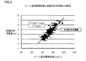
- 5 is a histogram of beam current amounts I 1 to I n per unit time until a predetermined film thickness d n is reached. For various beam current integrated value in the thickness S 1 ⁇ S n, it plots the deposition material consumption, resulting regression analysis obtained was beam current relationship between the integrated value and the film forming material consumption It is a graph which shows a type
- FIG. 1 is a block diagram of a film forming apparatus 1 according to a first embodiment of the present invention. It is a flowchart showing the flow of operation
- FIGS. 1 and 2A, 2B, and 2C First embodiment- A film forming apparatus 1 according to a first embodiment of the present invention will be described with reference to FIGS. 1 and 2A, 2B, and 2C.
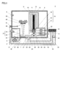
- FIG. 1 is a cross-sectional view of a film forming apparatus 1 according to the first embodiment of the present invention.
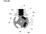
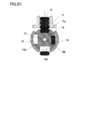
- 2A, 2B, and 2C are cross-sectional views in which the main part of the film forming material supply unit 9 in the film forming apparatus 1 shown in FIG. 1 is enlarged and described according to the operation state.
- the film forming apparatus 1 includes a first housing 2, a film forming material supply unit 9, a film forming material supply amount measuring unit 18, a hearth 25, a beam controller 31, a film forming material supply amount calculating unit 42, And a controller 43.
- the first housing 2 includes an exhaust pipe 4 connected to a vacuum pump 3, a vacuum gauge 5, a hermetic connector 6, magnetic fluid seals 7 and 8, a beam controller 31, and a film thickness meter 41. It is arranged.
- the inside of the first housing 2 is decompressed by the vacuum pump 3 through the exhaust pipe 4, and the degree of vacuum inside the first housing 2 is measured by the vacuum gauge 5.
- the hermetic connector 6 is pulled out from the drive unit 17 of the film formation material supply mechanism 13 and the detection unit 19 of the film formation material supply amount measurement unit 18 in the film formation material supply unit 9 and the controller 43 outside the first housing 2. Connected signal lines.
- the magnetic fluid seal 7 is connected to the drive unit 28 of the hearth rotating unit 24 and is disposed so as to surround a part of the peripheral side surface of the rotating shaft 27 that rotates the hearth 25.
- the magnetic fluid seal 8 is connected to the drive unit 38 of the shutter rotation unit 35 and is disposed so as to surround a part of the peripheral side surface of the rotation shaft 37 that rotates the shutter 36.
- the hermeticity of the first housing 2 is maintained by the hermetic connector 6 and the magnetic fluid seals 7 and 8.
- the beam controller 31 includes a beam source 32 and a control unit 33.
- the beam source 32 irradiates the film forming material 12 stored in a material receiving portion 26 provided in the hearth 25 described later with an electron beam 34 to vaporize the film forming material 12.
- the controller 33 controls the operation of the beam source 32, measures and integrates the amount of beam current flowing through the beam source 32, and calculates a beam current amount integrated value described later.
- the control unit 33 of the beam controller 31 is connected to the deposition material supply amount calculation unit 42, and the deposition material supply amount calculation unit 42 is connected to the controller 43. Therefore, an operation command from the controller 43 is transmitted to the control unit 33 via the deposition material supply amount calculation unit 42. That is, the operation of the beam controller 31 is controlled by the controller 43.
- the film thickness meter 41 measures the film thickness of the film forming material 12 deposited on the film forming member 40 supported by the support unit 39.
- the film formation material supply unit 9 includes a storage unit 10 and a film formation material supply mechanism 13.
- the storage unit 10 includes an inner cylinder 11 and stores the film forming material 12 in the inner cylinder 11.
- the film forming material 12 is in the form of pellets. Therefore, the storage unit 10 has a cartridge shape in which the film-forming material 12 is continuously packed in the inner cylinder 11 that can easily supply the pellet-shaped film-forming material 12 continuously.
- the film forming material supply mechanism 13 includes a holding unit 14, a rotating shaft 15, a guide 16 (see FIGS. 2A, 2B, and 2C), and a driving unit 17.
- the holding portion 14 has four concave portions 14a to 14d corresponding to the shape of the film forming material 12 formed on the outer peripheral surface of the cylinder.
- the holding unit 14 holds the film forming material 12 by storing the film forming material 12 in the recesses 14a to 14d.
- the holding unit 14 is arranged so as to close one end of the inner cylinder 11 of the storage unit 10.
- the rotating shaft 15 connects the holding unit 14 and the driving unit 17.
- the guide 16 covers the vicinity of the outer peripheral surface of the holding unit 14 in order to prevent the film forming material 12 stored in the recesses 14a to 14d from dropping at an unintended position when the holding unit 14 rotates. Is arranged.
- the driving unit 17 drives the holding unit 14 to supply the film forming material 12 to the material receiving unit 26 provided in the hearth 25 as described below.
- the driving unit 17 is connected to the controller 43 via the hermetic connector 6 described above. Therefore, an operation command from the controller 43 is transmitted to the drive unit 17. That is, the operation of the film forming material supply mechanism 13 is controlled by the controller 43.
- the operation of the film forming material supply mechanism 13 will be described with reference to FIGS. 2A, 2B, and 2C.
- the recesses 14a to 14d provided in the holding unit 14 are respectively set to 0 o'clock, 3 o'clock, 6 o'clock and 9 o'clock of the clock.
- the holding unit 14 is disposed so as to close one end portion of the inner cylinder 11 of the storage unit 10
- the film forming material 12 is stacked on the recess 14 a at the 0 o'clock position, and 3 o'clock.
- the film forming material 12 is stored in the recess 14b at the position.
- the holding unit 14 In the state where the film forming material supply mechanism 13 is operating, the holding unit 14 is rotated clockwise by the driving unit 17 as shown in FIG. 2B. With the rotation of the holding unit 14, the film forming material 12 stored in the recess 14 b is conveyed to a position of about 6 o'clock.
- a part 14e of the outer peripheral surface of the holding portion 14 supports the lowermost film forming material 12 from below so that the film forming material 12 stacked in the inner cylinder 11 does not fall. Further, the cover 16 prevents the film forming material 12 from dropping as described above.
- the film forming material 12 when the film forming material 12 is conveyed to the position of about 6 o'clock of the watch, the film forming material 12 passes through the opening 30 provided in the cover 29 as shown by an arrow. , Falls into the material receiving portion 26 of the hearth 25.
- cover 29 is provided to prevent the dropped film forming material 12 from jumping up, and is provided above the hearth 25.
- the film forming material supply amount measuring unit 18 is for measuring the number of falling film forming materials 12, and includes a detection unit 19 and a light emitting unit 20, both of which are integrated. A reflective photoelectric sensor is used. The light emitted from the light emitting unit 20 is reflected by the falling film forming material 12, and the reflected light enters the detection unit 19, whereby the number of film forming materials 12 is measured.
- the film-forming material 12 is a pellet-like metal and has a form and material that easily reflects light, the amount of film-forming material supplied can be accurately measured in a non-contact manner using such a photoelectric sensor. Can do.
- the case where a reflective photoelectric sensor is used as the film forming material supply amount measurement unit 18 has been described. However, the detection unit 19 and the light emitting unit 20 are separated. A transmissive photoelectric sensor may be used. In that case, the light emitting unit 20 is emitted from the light emitting unit 20 inside the second casing 21 to be described later, and the light incident on the detecting unit 19 is blocked by the falling film forming material 12. Can be installed in position.
- the detection unit 19 is connected to the controller 43 via the hermetic connector 6 described above. Therefore, the operation command from the controller 43 is transmitted to the detection unit 19. That is, the operation of the film forming material supply amount measuring unit 18 is controlled by the controller 43. Further, information on the measurement result of the film forming material supply amount is transmitted to the controller 43.
- the film formation material supply unit 9 and the film formation material supply amount measurement unit 18 are housed in a second housing 21 disposed in the first housing 2.
- the second housing 21 is provided with openings 22 and 23.
- the opening 22 is for passing a signal line connecting the driving unit 17 of the film forming material supply mechanism 13 and the hermetic connector 6.
- the opening 23 is for passing a signal line connecting the detection unit 19 of the film forming material supply amount measuring unit 18 and the hermetic connector 6.
- the second casing 21 converts the vapor of the film forming material 12 staying in the first casing 2 into the film forming material supply unit 9 and the film forming material.
- the supply amount measuring unit 18 is not attached.
- the vapor of the film forming material 12 staying in the first casing 2 adheres to the second casing 21 and becomes a thin film there. However, when a certain degree of film formation is observed, the second casing 21 is removed. If the cleaning is performed, the thin film does not peel from the second casing 21. Therefore, the inside of the first housing 2 is kept clean with no foreign matter.
- the film forming material supply unit 9 and the film forming material supply amount measuring unit 18 are protected from the heat of the electron beam, and the thermal load is reduced.
- the hearth rotating unit 24 includes a hearth 25, a rotating shaft 27, and a driving unit 28.
- the hearth 25 has a disk shape.
- the hearth 25 has a material receiving portion 26 that is a recess for storing the film forming material 12.
- a plurality of material receiving portions 26 are arranged so as to be concentric with the hearth 25.
- the material receiving portion 26 may be provided with a hearth liner (not shown) separate from the hearth.
- the hearth 25 is connected to a drive unit 28 by a rotating shaft 27, and the drive unit 28 is connected to a controller 43. Therefore, an operation command from the controller 43 is transmitted to the drive unit 28. That is, the operation of the hearth 25 is controlled by the controller 43.
- the shutter rotation unit 35 includes a shutter 36, a rotation shaft 37, and a drive unit 38.
- the shutter 36 is connected to a drive unit 38 by a rotation shaft 37, and the drive unit 38 is connected to a controller 43. Therefore, an operation command from the controller 43 is transmitted to the drive unit 38. That is, the operation of the shutter 36 is controlled by the controller 43.
- a correspondence relationship between the integrated value of the beam current up to the time when the film thickness is reached and the consumption amount of the film material up to the time when the film thickness is reached is input to the film forming material supply amount calculation unit 42 in advance. Yes. This correspondence will be described with reference to FIGS.
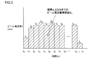
- FIG. 3 shows beam current amounts I 1 to I per unit time flowing to the beam source 32 in the beam controller 31 from the start of irradiation of the electron beam to the film forming material to the time when the predetermined film thickness dn is reached. It is a histogram of n .
- Beam current integrated value Sn is the amount of beam current I 1 ⁇ I n per unit time is obtained by integrating the control unit 33. That is, the beam current amount integrated value S n is the total area of the histogram shown in FIG. 3 (hatched portion), represented by the following formula (1).
- the film thickness d n is set to various thicknesses (d 1 , d 2 , d 3 ,%) By changing the supply amount of the film forming material 12, for example, and the beam current amount integrated value corresponding to the thickness is set. S n (S 1 , S 2 , S 3 ,%) Is measured.
- FIG. 4 shows the amount of film forming material consumption with respect to the beam current integrated values S 1 , S 2 , S 3 ,... Required up to the predetermined film thicknesses d 1 , d 2 , d 3 ,. Is a graph in which is plotted. The result of regression analysis of the result is shown in the following formula (2).
- the film forming material consumption can be calculated from the beam current amount integrated value within a predetermined error range.
- the deposition material replenishment amount calculation unit 42 calculates the deposition material consumption amount from the beam current amount integrated value information transmitted from the control unit 33, and further determines the deposition material replenishment amount corresponding to the deposition material consumption amount. Calculated. Further, information on the calculated deposition material supply amount is transmitted to the controller 43.
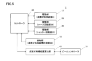
- FIG. 5 is a diagram showing a block diagram in the film forming apparatus 1.
- the drive unit 38 is connected to the controller 43.
- control unit 33 of the beam controller 31 is connected to a deposition material supply amount calculation unit 42, and the control unit 33 is connected to the controller 43 via the deposition material supply amount calculation unit 42.
- the controller 43 receives the measurement result of the deposition material supply amount by the detection unit 19 and the information on the deposition material supply amount by the deposition material supply amount calculation unit 42. Based on the information, the controller 43 determines whether or not the film forming material supply unit 9, the hearth 25 of the hearth rotating unit 24, the shutter 36 of the shutter rotating unit 35, and the beam controller 31 are necessary and driven. The operation command is transmitted to the units 17, 30 and 38 and the control unit 33.
- the operations of the film forming material supply unit 9, the hearth 25, the shutter 36, and the beam controller 31 are controlled by the controller 43.
- FIG. 6 is a flowchart showing a flow of information, determination, command, and operation in the film forming apparatus 1.
- step S101 the controller 33 of the beam controller 31 measures and integrates the beam current amount. This process is performed by a log function provided in the control unit 33.
- step S102 the control unit 33 compares the beam current amount integrated value up to that point with a predetermined value (reference value) set in advance.
- a predetermined value reference value
- the film thickness of the film forming material 12 deposited on the film forming member 40 is not a predetermined value, and the consumption of the film forming material 12 is completed. It is determined that it is not. Therefore, returning to step S101, measurement and integration of the beam current amount are continued.
- the film thickness of the film forming material 12 deposited on the film forming member 40 is a predetermined value, and the consumption of the film forming material 12 is completed. It is determined that Accordingly, the process proceeds to step S103.
- step S103 the controller 43 generates a shutter rotation command in response to the result of step S102. Further, the controller 43 transmits a shutter rotation command to the drive unit 38 of the shutter rotation unit 35. The drive unit 38 rotates the shutter 36 based on the operation command so that the vapor deposition on the film forming member 40 does not proceed any further.
- step S104 the controller 43 generates a stop command for the beam source 32 in response to the result of step S102. Further, the controller 43 transmits a stop command for the beam source 32 to the control unit 33 of the beam controller 31. The control unit 33 stops the beam source 32 based on the operation command.
- step S ⁇ b> 105 the film formation material supply amount calculation unit 42 receives the result of step S ⁇ b> 102 and forms a film from the correspondence relationship input in advance and the beam current amount integrated value information transmitted from the control unit 33. Calculate material consumption. Further, information on the calculated deposition material supply amount is transmitted to the controller 43.
- step S106 the controller 43 generates an operation command for the film forming material supply unit 9 in response to the result of step S105. Further, the controller 43 transmits an operation command to the drive unit 17 of the film forming material supply unit 9. Based on the operation command, the driving unit 17 rotates the holding unit 14 and supplies the film forming material 12 to the material receiving unit 26 provided in the hearth 25.
- step S107 the detecting unit 19 of the film forming material supply amount measuring unit 18 measures the film forming material supply amount to the material receiving unit 26 in response to the result of step S106.
- the deposition material supply amount is less than the calculated deposition material replenishment amount, it is determined that the replenishment of the deposition material 12 into the material receiving portion 26 is not completed. Accordingly, the process returns to step S106, and the supply of the film forming material 12 by the film forming material supply unit 9 is continued.
- step S108 when the deposition material supply amount becomes the calculated deposition material supply amount, it is determined that the deposition of the deposition material 12 into the material receiving portion 26 is completed. Accordingly, the process proceeds to step S108.
- step S108 the controller 43 generates an operation command for the hearth rotating unit 24 in response to the result of step S107. Further, the controller 43 transmits an operation command to the drive unit 28 of the hearth rotating unit 24. Based on the operation command, the drive unit 28 rotates the hearth 25 and conveys the replenished film forming material 12 to a position where the electron beam 34 from the beam source 32 is irradiated.
- step S109 the controller 43 generates a shutter rotation command in response to the result of step S108. Further, the controller 43 transmits a shutter rotation command to the drive unit 38 of the shutter rotation unit 35. The driving unit 38 rotates the shutter 36 based on the operation command so that vapor deposition on the film forming member 40 is possible.
- step S110 the controller 43 generates a drive command for the beam source 32 in response to the result of step S109. Further, the controller 43 transmits a drive command for the beam source 32 to the control unit 33 of the beam controller 31. Based on the operation command, the control unit 33 drives the beam source 32 to start vapor deposition on the film forming member 40.
- the film forming apparatus 1 according to the first embodiment has the apparatus configuration described above, an expensive camera device with high resolution is unnecessary, the structure of the film forming apparatus can be simplified, and the manufacturing cost can be reduced. Can do.
- the replenishment amount of the film forming material is not determined based on the image information obtained by the camera device, variation in the replenishment amount of the film forming material can be suppressed. Furthermore, since the film forming material can be replenished stably, continuous operation for a long time is possible.
- FIG. 7 is a cross-sectional view of a film forming material supply unit 9 and a film forming material supply amount measuring unit 18 constituting the film forming apparatus 1 according to the second embodiment of the present invention.
- the film forming apparatus 1 according to the second embodiment further includes a third casing 44 in addition to the components described in the first embodiment.
- the third housing 44 is disposed in the second housing 21 and houses the driving unit 17 and the film forming material supply amount measuring unit 18 of the film forming material supply mechanism 13.
- the film forming material supply amount measurement unit 18 is a reflective photoelectric sensor in which a detection unit 19 and a light emitting unit 20 are integrated.
- a transmission type photoelectric sensor in which the detection unit 19 and the light emitting unit 20 are separated can be used as the film forming material supply amount measurement unit 18. In that case, the detection part 19 should just be accommodated in the 3rd housing 44.
- the third housing 44 is provided with a hermetic connector 45, a magnetic fluid seal 46, and a glass window 47, and the inside can be maintained at atmospheric pressure.
- the hermetic connector 45 connects the signal line drawn from the drive unit 17 and the detection unit 19 to the hermetic connector 6.
- the light emitted from the light emitting unit 20 is reflected by the film forming material 12 that passes through the glass window 47 and falls, and the reflected light passes through the glass window 47 and enters the detection unit 19.
- the number of film forming materials 12 is measured.
- the film forming apparatus 1 according to the second embodiment has the above-described apparatus configuration, it is assumed that the driving unit 17 of the film forming material supply mechanism 13 and the detection unit 19 of the photoelectric sensor are used under reduced pressure. There is no need to use expensive special products.
Landscapes
- Chemical & Material Sciences (AREA)
- Chemical Kinetics & Catalysis (AREA)
- Engineering & Computer Science (AREA)
- Materials Engineering (AREA)
- Mechanical Engineering (AREA)
- Metallurgy (AREA)
- Organic Chemistry (AREA)
- Health & Medical Sciences (AREA)
- Toxicology (AREA)
- Physical Vapour Deposition (AREA)
Abstract
成膜装置(1)は、材料受け部(26)を有するハース(25)と、成膜材料(12)に電子ビーム(34)を照射するビーム源(32)と、ビーム源(32)に流れる単位時間当たりのビーム電流量を計測および積算して、成膜材料への電子ビーム(34)の照射が開始されてからのビーム電流量積算値を算出する制御部(33)と、を有するビームコントローラ(31)と、所定の膜厚となる時間までのビーム電流量積算値と、成膜材料消費量との対応関係が予め入力されており、制御部(33)により算出されたビーム電流量積算値から成膜材料消費量を算出し、対応する成膜材料補給量を算出する成膜材料補給量算出部(42)と、材料受け部(26)に成膜材料(12)を供給する成膜材料供給部(9)と、成膜材料供給量を計測する成膜材料供給量計測部(18)と、コントローラ(43)と、を有する。
Description
この発明は、成膜材料に電子ビームを照射して加熱することにより気化させ、気化した成膜材料を基材上に堆積させることにより、薄膜を成形する成膜装置に関するものである。
昨今、種々のデバイスの高性能化、小型化には、薄膜成形技術が幅広く用いられている。薄膜の生産性を高めるには、長時間に亘って安定して成膜できる成膜装置が必要である。
その一例として、特開2011-105966号公報(特許文献1)には、ハースの材料受け部上の成膜材料量を常に一定として、安定した蒸着を可能とした成膜装置が提案されている。
特許文献1に記載の成膜装置101を図8に示す。成膜装置101は、成膜材料112を電子ビーム134で加熱、溶融して、被成膜部材140上に蒸着させる電子ビーム蒸着装置である。成膜材料112は、回転軸129により回転する円板状のハース125の、同心円状にくり抜かれた材料受け部126に収容されている。
この成膜材料112は、成膜に伴う加熱、蒸発により消費されるため、成膜装置101には、ハース125の材料受け部126に成膜材料112を補給する成膜材料供給装置109が連結されている。
この成膜材料供給装置109は、必要量の成膜材料を貯蔵する材料ホッパー110と、材料フィーダ113と、材料受け部126内の成膜材料112の量を監視するカメラ装置118と、制御部143とを備えている。
制御部143は、カメラ装置118から得られた成膜材料112の画像を予め設定した画像と比較することにより、成膜材料112の量を判別し、材料フィーダ113から材料受け部126への成膜材料112の補給量を制御している。
成膜装置101において、ハース125上で成膜材料112が供給される位置と、電子ビーム134の照射位置とは、ハース125の回転軸129に対して対称な位置にある。すなわち、成膜材料供給装置109から材料受け部126に補給された成膜材料112は、ハース125の回転によって電子ビーム134の照射位置まで搬送された後、電子ビーム134が照射されて蒸発する。
特許文献1では、成膜装置101は、上記の構成により、電子ビームが照射される位置における材料受け部126内の成膜材料112の量を一定とすることができ、長時間に亘って安定した成膜を実現することができるとされている。
特許文献1に記載の成膜装置101では、成膜材料112の量の監視に、高解像度の高額なカメラ装置118が必要となるため、成膜装置101の製造コストが高くなってしまう。
また、成膜装置101内の真空度を維持しつつ、成膜装置101への取り付けを高精度で行なう必要があるため、カメラ装置118のマウンタなどに特別な部品が必要となる。また、組み付けのための複雑な機構も必要となる。
さらに、成膜材料112の形態および量によっては、材料受け部126内の成膜材料112の量が、カメラ装置118により得られた画像情報からは判別し難く、成膜材料112の補給量にばらつきが生じる可能性がある。
そこで、この発明の目的は、低コストで製造できる簡便な構造を有し、成膜材料の補給量のばらつきを抑制できる成膜装置を提供することである。
この発明では、低コストで製造できる簡便な構造を有し、成膜材料の補給量のばらつきを抑えることができる成膜装置を提供するため、成膜材料の補給量を決定する機構についての改良が図られる。
この発明に係る成膜装置は、ハースと、ビームコントローラと、成膜材料補給量算出部と、成膜材料供給部と、成膜材料供給量計測部と、第1の筺体と、コントローラと、を有する。
ハースは、成膜材料を収納する材料受け部を有する。
ビームコントローラは、ビーム源と、制御部と、を有する。ビーム源は、材料受け部に収納された成膜材料に電子ビームを照射する。制御部は、ビーム源の動作を制御し、かつビーム源に流れる単位時間当たりのビーム電流量を計測および積算して、成膜材料への電子ビームの照射が開始されてからのビーム電流量積算値を算出する。
ビームコントローラは、ビーム源と、制御部と、を有する。ビーム源は、材料受け部に収納された成膜材料に電子ビームを照射する。制御部は、ビーム源の動作を制御し、かつビーム源に流れる単位時間当たりのビーム電流量を計測および積算して、成膜材料への電子ビームの照射が開始されてからのビーム電流量積算値を算出する。
成膜材料補給量算出部には、所定の膜厚となる時間までのビーム電流量積算値と、所定の膜厚となる時間までの成膜材料消費量との対応関係が予め入力されている。また、成膜材料補給量算出部は、ビームコントローラの制御部により算出されたビーム電流量積算値が伝達され、上記の対応関係に基づいて成膜材料消費量を算出し、成膜材料消費量に対応した成膜材料補給量を算出する。
成膜材料供給部は、成膜材料を貯蔵する貯蔵部と、成膜材料を保持する保持部および保持部を駆動して成膜材料を材料受け部に供給する駆動部を備えた成膜材料供給機構と、を有する。
成膜材料供給量計測部は、材料受け部への成膜材料供給量を計測する。
第1の筺体は、内部を減圧状態に維持可能であり、ハースと、ビーム源と、成膜材料供給部と、成膜材料供給量計測部と、を収納する。
第1の筺体は、内部を減圧状態に維持可能であり、ハースと、ビーム源と、成膜材料供給部と、成膜材料供給量計測部と、を収納する。
コントローラは、成膜材料供給量および成膜材料投入量の情報に基づき、ハースと、ビームコントローラと、成膜材料供給部と、の動作を制御する。
上記の成膜装置では、ビーム電流量積算値と、成膜材料消費量との対応関係が予め求められており、成膜材料補給量算出部に入力されている。そして、成膜材料補給量算出部は、その対応関係に基づいて、成膜材料への電子ビームの照射が開始されてからのビーム電流量積算値から成膜材料消費量を算出し、成膜材料消費量に対応した成膜材料補給量を算出するようにしている。
そのため、高額なカメラ装置を用いて、材料受け部内の成膜材料の量を監視する必要がない。したがって、カメラ装置のマウンタなどの特別な部品が不要となる。また、組み付けのための複雑な機構も不要となる。
すなわち、成膜装置が、低コストで製造できる簡便な構造となる。また、成膜材料補給量をカメラ装置により得られた画像情報に基づいて決定することがないため、成膜材料の補給量のばらつきを抑制できる。
さらに、成膜材料を安定して補給できるため、長時間の連続運転を行なうことが可能となる。
この発明に係る成膜装置は、第1の筺体内に配置され、成膜材料供給部と、成膜材料供給量計測部と、を収納する第2の筺体を有する構造としてもよい。
上記の成膜装置では、成膜材料供給部および成膜材料供給量計測部が、第2の筺体内に収納されている。したがって、成膜装置を長時間に亘って連続運転した場合でも、第1の筺体内に滞留した成膜材料の蒸気は、特に高い精度で組み付ける必要のない第2の筺体に付着し、成膜材料供給部および成膜材料供給量計測部に付着することがない。
すなわち、第2の筺体を洗浄する必要が生じた場合でも、第2の筺体を取り外し、酸によるエッチングなどで洗浄した後、再び成膜装置に組み付けることにより、容易に洗浄作業を行なうことができる。
また、成膜装置から取り外して再び組み付けるのは、単純な構造を有する第2の筺体のみであるため、成膜材料供給部および成膜材料供給量計測部の動作に影響を及ぼす不具合が発生することがない。
さらに、成膜材料供給部および成膜材料供給量計測部が、直に電子ビームの熱にさらされることがないため、成膜材料供給部および成膜材料供給量計測部にかかる熱的負荷を低減できる。
すなわち、成膜材料供給部および成膜材料供給量計測部の寿命、延いては成膜装置の寿命を延ばすことができる。
この発明に係る成膜装置は、成膜材料供給量計測部として、光電センサを用いてもよい。
上記の成膜装置では、成膜材料供給量計測部として、光電センサを用いているため、非接触で成膜材料供給量を計測することができる。
光電センサには、反射型および透過型の2種類がある。成膜材料は金属であるため、発光部から発せられた光を反射しやすく、反射型の光電センサの場合、検知部が反射光を確実に検知することができる。一方、成膜材料がペレット状または球状など所定の体積を有する形状であれば、発光部からの光を遮りやすく、透過型の光電センサの場合、検知部が遮光を確実に検知することができる。したがって、いずれの形態の光電センサを用いても、1個ずつ確実に供給量を計測できる。
すなわち、成膜材料供給量を精度よく計測することができる。
この発明に係る成膜装置は、第2の筺体内に配置され、成膜材料供給機構の駆動部および光電センサの検知部を収納し、内部を大気圧に維持可能な第3の筺体と、を有する構造としてもよい。
この発明に係る成膜装置は、第2の筺体内に配置され、成膜材料供給機構の駆動部および光電センサの検知部を収納し、内部を大気圧に維持可能な第3の筺体と、を有する構造としてもよい。
上記の成膜装置では、内部を大気圧に維持可能な第3の筺体に成膜材料供給機構の駆動部および光電センサの検知部を収納している。したがって、成膜材料供給機構の駆動部および光電センサの検知部に、減圧下での使用を前提とした、高価な特殊品を用いる必要がない。
すなわち、大気圧下での使用を前提とした安価な通常品を用いることができるため、成膜装置の製造コストが低減できる。また、減圧下での使用を前提とし、複雑な構造を有する特殊品を使用した場合に比べて、メンテナンスを容易に行なうことができる。
この発明に係る成膜装置は、ビーム電流量積算値と、成膜材料消費量との対応関係が予め求められており、成膜材料補給量算出部に入力されている。そして、成膜材料補給量算出部は、その対応関係に基づいて、成膜材料への電子ビームの照射が開始されてからのビーム電流量積算値から成膜材料消費量を算出し、成膜材料消費量に対応した成膜材料補給量を算出するようにしている。その結果、高解像度の高額なカメラ装置が不要となり、成膜装置の構造を簡便にでき、かつ製造コストを下げることができる。
また、成膜材料補給量をカメラ装置により得られた画像情報に基づいて決定することがないため、成膜材料の補給量のばらつきを抑制ができる。さらに、成膜材料を安定して補給できるため、長時間の連続運転が可能となる。
-第1の実施形態-
この発明の第1の実施形態に係る成膜装置1について、図1および図2A,図2B,図2Cを用いて説明する。
この発明の第1の実施形態に係る成膜装置1について、図1および図2A,図2B,図2Cを用いて説明する。
図1は、この発明の第1の実施形態に係る成膜装置1の断面図である。また、図2A,図2B,図2Cは、図1に示した成膜装置1における成膜材料供給部9の主要部を拡大し、その動作状態に応じて説明した断面図である。
成膜装置1は、第1の筺体2と、成膜材料供給部9と、成膜材料供給量計測部18と、ハース25と、ビームコントローラ31と、成膜材料補給量算出部42と、コントローラ43と、を有する。
第1の筺体2には、真空ポンプ3に接続される排気管4と、真空計5と、ハーメチックコネクタ6と、磁性流体シール7、8と、ビームコントローラ31と、膜厚計41と、が配設されている。
第1の筺体2の内部は、排気管4を介して真空ポンプ3により減圧され、第1の筺体2の内部の真空度は真空計5で計測される。
ハーメチックコネクタ6は、成膜材料供給部9における成膜材料供給機構13の駆動部17および成膜材料供給量計測部18の検知部19と、第1の筺体2外のコントローラ43と、から引き出されている信号ラインを接続している。
磁性流体シール7は、ハース回転部24の駆動部28に接続され、ハース25を回転させる回転軸27の周側面の一部を囲むように配置されている。
磁性流体シール8は、シャッター回転部35の駆動部38に接続され、シャッター36を回転させる回転軸37の周側面の一部を囲むように配置されている。
第1の筺体2の気密性は、ハーメチックコネクタ6および磁性流体シール7、8により維持されている。
ビームコントローラ31は、ビーム源32および制御部33と、を有する。ビーム源32は、後述のハース25に設けられた材料受け部26に収納された成膜材料12に電子ビーム34を照射し、成膜材料12を気化させる。制御部33は、ビーム源32の動作を制御し、かつビーム源32に流れるビーム電流量を計測および積算して、後述のビーム電流量積算値を算出する。
ビームコントローラ31の制御部33は、成膜材料補給量算出部42と接続され、また、成膜材料補給量算出部42はコントローラ43と接続されている。したがって、制御部33には、成膜材料補給量算出部42を介して、コントローラ43からの動作指令が伝達される。すなわち、ビームコントローラ31の動作は、コントローラ43により制御されている。
膜厚計41は、支持部39によって支持されている被成膜部材40上に蒸着された成膜材料12の膜厚を計測する。
成膜材料供給部9は、貯蔵部10と、成膜材料供給機構13と、を有する。貯蔵部10は、内筒11を有し、内筒11の内部に成膜材料12を貯蔵する。第1の実施例において、成膜材料12は、ペレット状である。したがって、貯蔵部10は、ペレット状の成膜材料12を連続的に供給しやすい、内筒11の内部に成膜材料12が連続的に詰め込まれたカートリッジ状となっている。
成膜材料供給機構13は、保持部14と、回転軸15と、ガイド16(図2A,図2B,図2C参照)と、駆動部17と、を有する。第1の実施例において、保持部14は、成膜材料12の形状に対応した凹部14a~14dが、円柱の外周面に4箇所形成されたものである。
保持部14は、それらの凹部14a~14dに成膜材料12を収納することにより、成膜材料12を保持する。また、保持部14は、貯蔵部10の内筒11の一方端部を閉塞するように配置されている。
回転軸15は、保持部14と駆動部17とを接続する。ガイド16は、保持部14が回転した際に、凹部14a~14dに収納されている成膜材料12が、意図しない位置で落下するのを防止するため、保持部14の外周面近傍を覆うように配置されている。駆動部17は、保持部14を駆動して、下記のように成膜材料12をハース25に設けられた材料受け部26に供給する。
駆動部17は、前述のハーメチックコネクタ6を介してコントローラ43と接続されている。したがって、駆動部17には、コントローラ43からの動作指令が伝達される。すなわち、成膜材料供給機構13の動作は、コントローラ43により制御されている。
成膜材料供給機構13の動作について、図2A,図2B,図2Cを参照して説明する。
成膜材料供給機構13が停止している状態では、図2Aに示すように、保持部14に設けられた凹部14a~14dは、それぞれ時計の0時、3時、6時、および9時の位置にある。前述のように、保持部14は、貯蔵部10の内筒11の一方端部を閉塞するように配置されているため、0時の位置の凹部14a上に成膜材料12が積み重なり、3時の位置の凹部14bに成膜材料12が収納された状態となっている。
成膜材料供給機構13が停止している状態では、図2Aに示すように、保持部14に設けられた凹部14a~14dは、それぞれ時計の0時、3時、6時、および9時の位置にある。前述のように、保持部14は、貯蔵部10の内筒11の一方端部を閉塞するように配置されているため、0時の位置の凹部14a上に成膜材料12が積み重なり、3時の位置の凹部14bに成膜材料12が収納された状態となっている。
成膜材料供給機構13が動作している状態では、図2Bに示すように保持部14は駆動部17によって、時計回りに回転する。保持部14の回転に伴い、凹部14bに収納されていた成膜材料12が、およそ6時の位置にまで搬送される。
その際、保持部14の外周面の一部14eは、内筒11の内部に積み重なっている成膜材料12が落下しないように、一番下にある成膜材料12を下方から支えている。また、カバー16は、前述のように成膜材料12の落下を防止している。
図2Cに示すように成膜材料12が時計のおよそ6時の位置にまで搬送されると、成膜材料12は、矢印で示したように、カバー29に設けられた開口部30を通って、ハース25の材料受け部26内に落下する。
なお、カバー29は、落下した成膜材料12が跳ね上がらないようにするためのものであり、ハース25の上方に設けられている。
成膜材料供給量計測部18は、落下してくる成膜材料12の個数を計測するためのものであり、検知部19と、発光部20と、を有し、両者が一体となっている反射型の光電センサが用いられている。発光部20から発せられた光は、落下してくる成膜材料12により反射され、その反射光が検知部19に入射することにより、成膜材料12の個数が計測される。
成膜材料12は、ペレット状の金属であり、など光を反射しやすい形態および材質であるため、このような光電センサを用いることにより、非接触で成膜材料供給量を精度よく計測することができる。
なお、第1の実施例においては、成膜材料供給量計測部18として、反射型の光電センサが用いられている場合について説明したが、検知部19と、発光部20とが別体となっている透過型の光電センサを用いてもよい。その場合、発光部20は、後述の第2の筺体21の内部で、発光部20により発せられ、検知部19に入射している光が、落下してくる成膜材料12によって遮られるような位置に設置することができる。
検知部19は、前述のハーメチックコネクタ6を介してコントローラ43と接続されている。したがって、検知部19にコントローラ43からの動作指令が伝達される。すなわち、成膜材料供給量計測部18の動作は、コントローラ43により制御されている。さらに、成膜材料供給量の計測結果の情報は、コントローラ43に伝達される。
成膜材料供給部9および成膜材料供給量計測部18は、第1の筺体2の内部に配置されている第2の筺体21の内部に収納されている。第2の筺体21には、開口部22、23が設けられている。
開口部22は、成膜材料供給機構13の駆動部17と、ハーメチックコネクタ6と、を接続する信号ラインを通すためのものである。また、開口部23は、成膜材料供給量計測部18の検知部19と、ハーメチックコネクタ6と、を接続する信号ラインを通すためのものである。
第2の筺体21は、成膜装置1を長時間に亘って連続運転した場合に、第1の筺体2内に滞留した成膜材料12の蒸気を、成膜材料供給部9および成膜材料供給量計測部18に付着させないようにしている。
第1の筺体2内に滞留した成膜材料12の蒸気は、第2の筺体21に付着し、そこで薄膜となるが、ある程度の着膜が認められた場合、第2の筺体21を取り外して洗浄するようにすれば、第2の筺体21から薄膜が剥離することはない。したがって、第1の筺体2内は、異物のない、清浄な状態に保たれる。
また、成膜装置から取り外して再び組み付けるのは、単純な構造を有する第2の筺体のみであるため、成膜材料供給部および成膜材料供給量計測部の動作に影響を及ぼす不具合が発生することはない。
さらに、成膜材料供給部9および成膜材料供給量計測部18を、電子ビームの熱から守り、熱的負荷を低減させている。
ハース回転部24は、ハース25と、回転軸27と、駆動部28と、を有する。第1の実施例において、ハース25は、円板状となっている。また、ハース25は、成膜材料12を収納する凹部である材料受け部26を有している。材料受け部26は、ハース25と同心円状になるように複数配列されている。なお、材料受け部26には、ハースとは別体のハースライナ(不図示)を設けてもよい。
ハース25は、回転軸27によって、駆動部28と接続されており、駆動部28はコントローラ43と接続されている。したがって、駆動部28には、コントローラ43からの動作指令が伝達される。すなわち、ハース25の動作は、コントローラ43により制御されている。
シャッター回転部35は、シャッター36と、回転軸37と、駆動部38と、を有する。シャッター36は、回転軸37によって、駆動部38と接続されており、駆動部38はコントローラ43と接続されている。したがって、駆動部38には、コントローラ43からの動作指令が伝達される。すなわち、シャッター36の動作は、コントローラ43により制御されている。
成膜材料補給量算出部42には、所定の膜厚となる時間までのビーム電流量積算値と、所定の膜厚となる時間までの成膜材料消費量との対応関係が予め入力されている。この対応関係について、図3、4を用いて説明する。
図3は、ビームコントローラ31において、成膜材料への電子ビームの照射が開始されてから所定の膜厚dnとなる時間までに、ビーム源32に流れる単位時間当たりのビーム電流量I1~Inのヒストグラムである。
ビーム電流量積算値Snは、この単位時間当たりのビーム電流量I1~Inを、制御部33で積算することにより得られる。すなわち、ビーム電流量積算値Snは、図3に示されているヒストグラムの総面積(斜線部)であり、下式(1)で表される。

なお、ビーム源32に流れる単位時間当たりのビーム電流量I1~Inは、制御部33に設けられているログ機能によって、データを取得および格納し、膜厚dnは、膜厚計36により測定することができる。
この膜厚dnを、例えば成膜材料12の供給量を変更することにより種々の厚さ(d1、d2、d3、・・・)に設定し、それに対応したビーム電流量積算値Sn(S1、S2、S3、・・・)を測定する。
図4は、所定の膜厚d1、d2、d3、・・・となる時間までに要したビーム電流量積算値S1、S2、S3、・・・に対する成膜材料消費量をプロットしたグラフである。また、その結果を回帰分析した結果を下式(2)に示す。
回帰分析の結果から、ビーム電流量積算値と成膜材料消費量との間には、強い相関性があり、また上記の式で表される対応関係があることが分かる。
すなわち、この対応関係に基づいて、所定の誤差の範囲内で、ビーム電流量積算値から成膜材料消費量を算出できると考えられる。
成膜材料補給量算出部42では、制御部33から伝達されたビーム電流量積算値の情報から成膜材料消費量が算出され、さらにその成膜材料消費量に対応した成膜材料補給量が算出される。また、算出された成膜材料補給量の情報は、コントローラ43に伝達される。
なお、第1の実施例においては、ビーム電流量積算値と成膜材料消費量との関係は直線的に変化していると見なすことができる。したがって、1次式として回帰分析することが適切と判断できるため、そのようにした場合の分析結果について示した。
一方、プロットした結果によっては、2次以上の高次の式、指数関数および対数関数などが、相関性を適切に表すと判断できる場合も考えられる。その場合には、そのような適切と考えられる他の式による回帰分析を行なってもよい。
以上で説明した各構成要素を有する成膜装置1の動作について、図5、6を用いて説明する。
図5は、成膜装置1におけるブロック線図を示した図である。成膜材料供給部9の駆動部17と、成膜材料供給量計測部18の検知部19と、成膜材料補給量算出部42と、ハース回転部24の駆動部28と、シャッター回転部35の駆動部38とは、それぞれコントローラ43に接続されている。
また、ビームコントローラ31の制御部33は、成膜材料補給量算出部42に接続されており、制御部33は、成膜材料補給量算出部42を介して、コントローラ43に接続されている。
コントローラ43には、検知部19による成膜材料供給量の計測結果、および成膜材料補給量算出部42による成膜材料補給量の情報が伝達される。コントローラ43は、それらの情報に基づいて、成膜材料供給部9と、ハース回転部24のハース25と、シャッター回転部35のシャッター36と、ビームコントローラ31の動作の要否を決定し、駆動部17、30、38と、制御部33に動作指令を伝達する。
すなわち、成膜材料供給部9と、ハース25と、シャッター36と、ビームコントローラ31と、の動作は、コントローラ43によって制御されている。
図6は、成膜装置1内における、情報、判定、指令および動作の流れを示すフローチャートである。
ステップS101では、ビームコントローラ31の制御部33は、ビーム電流量の測定および積算を行なう。この処理は、制御部33に備えられているログ機能により行なわれる。
ステップS102では、制御部33は、その時点までのビーム電流量積算値と、予め設定されている所定の値(基準値)と比較する。ビーム電流量積算値が基準値未満である場合、被成膜部材40上に蒸着された成膜材料12の膜厚が、所定の値になっておらず、成膜材料12の消費が完了していないと判定される。したがって、ステップS101に戻り、ビーム電流量の測定および積算が継続される。
一方、ビーム電流量積算値が基準値以上である場合、被成膜部材40上に蒸着された成膜材料12の膜厚が、所定の値となっており、成膜材料12の消費が完了したと判定される。したがって、ステップS103に進む。
ステップS103では、コントローラ43は、ステップS102の結果を受けて、シャッター回転指令を発生させる。また、コントローラ43は、シャッター回転部35の駆動部38に、シャッター回転指令を伝達する。駆動部38は、その動作指令に基づき、シャッター36を回転させ、被成膜部材40上の蒸着がこれ以上進まないようにする。
ステップS104では、コントローラ43は、ステップS102の結果を受けて、ビーム源32の停止指令を発生させる。また、コントローラ43は、ビームコントローラ31の制御部33に、ビーム源32の停止指令を伝達する。制御部33は、その動作指令に基づき、ビーム源32を停止させる。
ステップS105では、成膜材料補給量算出部42は、ステップS102の結果を受けて、予め入力されている対応関係と、制御部33から伝達されたビーム電流量積算値の情報とから、成膜材料消費量を算出する。また、算出された成膜材料補給量の情報は、コントローラ43に伝達される。
ステップS106では、コントローラ43は、ステップS105の結果を受けて、成膜材料供給部9の動作指令を発生させる。また、コントローラ43は、成膜材料供給部9の駆動部17に、動作指令を伝達する。駆動部17は、その動作指令に基づき、保持部14を回転させ、ハース25に設けられた材料受け部26に成膜材料12を供給する。
ステップS107では、成膜材料供給量計測部18の検知部19は、ステップS106の結果を受けて、材料受け部26への成膜材料供給量を計測する。成膜材料供給量が算出された成膜材料補給量未満である場合、材料受け部26内への成膜材料12の補給が完了していないと判定される。したがって、ステップS106に戻り、成膜材料供給部9による成膜材料12の供給が継続される。
一方、成膜材料供給量が算出された成膜材料補給量となった場合、材料受け部26内への成膜材料12の補給が完了したと判定される。したがって、ステップS108に進む。
ステップS108では、コントローラ43は、ステップS107の結果を受けて、ハース回転部24の動作指令を発生させる。また、コントローラ43は、ハース回転部24の駆動部28に、動作指令を伝達する。駆動部28は、その動作指令に基づき、ハース25を回転させ、補給された成膜材料12に、ビーム源32からの電子ビーム34が照射される位置に搬送する。
ステップS109では、コントローラ43は、ステップS108の結果を受けて、シャッター回転指令を発生させる。また、コントローラ43は、シャッター回転部35の駆動部38に、シャッター回転指令を伝達する。駆動部38は、その動作指令に基づき、シャッター36を回転させ、被成膜部材40への蒸着が可能な状態とする。
ステップS110では、コントローラ43は、ステップS109の結果を受けて、ビーム源32の駆動指令を発生させる。また、コントローラ43は、ビームコントローラ31の制御部33に、ビーム源32の駆動指令を伝達する。制御部33は、その動作指令に基づき、ビーム源32を駆動させ、被成膜部材40への蒸着を開始する。
第1の実施形態に係る成膜装置1は、以上で説明した装置構成を有するため、高解像度の高額なカメラ装置が不要となり、成膜装置の構造を簡便にでき、かつ製造コストを下げることができる。
また、成膜材料補給量をカメラ装置により得られた画像情報に基づいて決定することがないため、成膜材料の補給量のばらつきを抑制できる。さらに、成膜材料を安定して補給できるため、長時間の連続運転が可能となる。
-第2の実施形態-
この発明の第2の実施形態に係る成膜装置1の要部について、図7を用いて説明する。その他の部分については、第1の実施形態と同様であるため、説明を省略する。
この発明の第2の実施形態に係る成膜装置1の要部について、図7を用いて説明する。その他の部分については、第1の実施形態と同様であるため、説明を省略する。
図7は、この発明の第2の実施形態に係る成膜装置1を構成する成膜材料供給部9および成膜材料供給量計測部18の断面図である。
第2の実施形態に係る成膜装置1は、第1の実施形態で説明した各構成要素に加え、第3の筺体44をさらに有する。第3の筺体44は、第2の筺体内21に配置され、成膜材料供給機構13の駆動部17および成膜材料供給量計測部18を収納する。
成膜材料供給量計測部18は、検知部19と、発光部20とが一体となっている反射型の光電センサである。一方、成膜材料供給量計測部18として、検知部19と、発光部20とが別体となっている透過型の光電センサを用いることもできる。その場合は、検知部19が第3の筺体44内に収納されていればよい。
第3の筺体44には、ハーメチックコネクタ45と、磁性流体シール46と、ガラス窓47と、が配設されており、内部が大気圧に維持可能となっている。
ハーメチックコネクタ45は、駆動部17および検知部19と、ハーメチックコネクタ6と、から引き出されている信号ラインを接続している。また、発光部20から発せられた光は、ガラス窓47を透過して落下してくる成膜材料12により反射され、その反射光がガラス窓47を透過して検知部19に入射することにより、成膜材料12の個数が計測される。
第2の実施形態に係る成膜装置1は、以上で説明した装置構成を有するため、成膜材料供給機構13の駆動部17および光電センサの検知部19に、減圧下での使用を前提とした高価な特殊品を用いる必要がない。
すなわち、大気圧下での使用を前提とした安価な通常品を用いることができるため、成膜装置1の製造コストが低減できる。また、減圧下での使用を前提とし、複雑な構造を有する特殊品を使用した場合に比べて、メンテナンスを容易に行なうことができる。
なお、この発明は上記の実施形態に限定されるものではなく、この発明の範囲内において、種々の応用、変形を加えることが可能である。
1 成膜装置、2 第1の筺体、9 成膜材料供給部、10 貯蔵部、12 成膜材料、13 成膜材料供給機構、14 保持部、17 駆動部、18 成膜材料供給量計測部、21 第2の筺体、25 ハース、26 材料受け部、31 ビームコントローラ、32 ビーム源、33 制御部、34 電子ビーム、42 成膜材料補給量算出部、43 コントローラ、44 第3の筺体、47 第4の筺体。
Claims (4)
- 成膜材料を収納する材料受け部を有するハースと、
前記材料受け部に収納された前記成膜材料に電子ビームを照射するビーム源と、前記ビーム源の動作を制御し、かつ前記ビーム源に流れる単位時間当たりのビーム電流量を計測および積算して、前記成膜材料への前記電子ビームの照射が開始されてからのビーム電流量積算値を算出する制御部と、を有するビームコントローラと、
所定の膜厚となる時間までのビーム電流量積算値と、前記所定の膜厚となる時間までの成膜材料消費量との対応関係が予め入力されており、前記制御部により算出されたビーム電流量積算値から、前記対応関係に基づいて成膜材料消費量を算出し、当該成膜材料消費量に対応した成膜材料補給量を算出する成膜材料補給量算出部と、
前記成膜材料を貯蔵する貯蔵部と、前記成膜材料を保持する保持部および前記保持部を駆動して前記成膜材料を前記材料受け部に供給する駆動部を備えた成膜材料供給機構と、を有する成膜材料供給部と、
前記材料受け部への成膜材料供給量を計測する成膜材料供給量計測部と、
前記ハースと、前記ビーム源と、前記成膜材料供給部と、前記成膜材料供給量計測部と、を収納し、かつ内部を減圧状態に維持可能な第1の筺体と、
前記成膜材料補給量および前記成膜材料供給量の情報に基づき、前記ハースと、前記ビームコントローラと、前記成膜材料供給部と、の動作を制御するコントローラと、を有することを特徴とする、成膜装置。 - 前記第1の筺体内に配置され、前記成膜材料供給部と、前記成膜材料供給量計測部と、を収納する第2の筺体を有することを特徴とする、請求項1に記載の成膜装置。
- 前記成膜材料供給量計測部が、光電センサであることを特徴とする、請求項2に記載の成膜装置。
- 前記第2の筺体内に配置され、前記成膜材料供給機構の駆動部および前記光電センサの検知部を収納し、内部を大気圧に維持可能な第3の筺体と、を有することを特徴とする、請求項3に記載の成膜装置。
Priority Applications (1)
| Application Number | Priority Date | Filing Date | Title |
|---|---|---|---|
| JP2015535388A JP5910797B2 (ja) | 2013-09-05 | 2014-08-01 | 成膜装置 |
Applications Claiming Priority (2)
| Application Number | Priority Date | Filing Date | Title |
|---|---|---|---|
| JP2013-183733 | 2013-09-05 | ||
| JP2013183733 | 2013-09-05 |
Publications (1)
| Publication Number | Publication Date |
|---|---|
| WO2015033713A1 true WO2015033713A1 (ja) | 2015-03-12 |
Family
ID=52628198
Family Applications (1)
| Application Number | Title | Priority Date | Filing Date |
|---|---|---|---|
| PCT/JP2014/070328 Ceased WO2015033713A1 (ja) | 2013-09-05 | 2014-08-01 | 成膜装置 |
Country Status (2)
| Country | Link |
|---|---|
| JP (1) | JP5910797B2 (ja) |
| WO (1) | WO2015033713A1 (ja) |
Cited By (2)
| Publication number | Priority date | Publication date | Assignee | Title |
|---|---|---|---|---|
| JP2016091593A (ja) * | 2014-10-29 | 2016-05-23 | 株式会社Cics | 蒸発材料補充装置及び蒸発材料補充方法 |
| JP7430961B1 (ja) * | 2023-05-18 | 2024-02-14 | 株式会社シンクロン | 成膜装置及びこれに用いられる材料供給装置 |
Families Citing this family (1)
| Publication number | Priority date | Publication date | Assignee | Title |
|---|---|---|---|---|
| CN111934645B (zh) * | 2020-08-13 | 2023-03-24 | 厦门市三安集成电路有限公司 | 铝铜合金膜层的制备方法、声表面波滤波器以及双工器 |
Citations (5)
| Publication number | Priority date | Publication date | Assignee | Title |
|---|---|---|---|---|
| JP2000054127A (ja) * | 1998-07-30 | 2000-02-22 | Sumitomo Heavy Ind Ltd | 真空成膜装置 |
| JP2011105966A (ja) * | 2009-11-13 | 2011-06-02 | Panasonic Corp | 成膜材料供給装置 |
| WO2013014410A1 (en) * | 2011-07-23 | 2013-01-31 | Bostech Ltd | Electron beam evaporation apparatus |
| WO2013073201A1 (ja) * | 2011-11-16 | 2013-05-23 | 三菱重工業株式会社 | 真空蒸着装置 |
| JP2013104084A (ja) * | 2011-11-11 | 2013-05-30 | Hitachi Zosen Corp | 電子ビーム蒸着用材料供給装置及び方法並びに電子ビーム蒸着装置 |
-
2014
- 2014-08-01 JP JP2015535388A patent/JP5910797B2/ja active Active
- 2014-08-01 WO PCT/JP2014/070328 patent/WO2015033713A1/ja not_active Ceased
Patent Citations (5)
| Publication number | Priority date | Publication date | Assignee | Title |
|---|---|---|---|---|
| JP2000054127A (ja) * | 1998-07-30 | 2000-02-22 | Sumitomo Heavy Ind Ltd | 真空成膜装置 |
| JP2011105966A (ja) * | 2009-11-13 | 2011-06-02 | Panasonic Corp | 成膜材料供給装置 |
| WO2013014410A1 (en) * | 2011-07-23 | 2013-01-31 | Bostech Ltd | Electron beam evaporation apparatus |
| JP2013104084A (ja) * | 2011-11-11 | 2013-05-30 | Hitachi Zosen Corp | 電子ビーム蒸着用材料供給装置及び方法並びに電子ビーム蒸着装置 |
| WO2013073201A1 (ja) * | 2011-11-16 | 2013-05-23 | 三菱重工業株式会社 | 真空蒸着装置 |
Cited By (3)
| Publication number | Priority date | Publication date | Assignee | Title |
|---|---|---|---|---|
| JP2016091593A (ja) * | 2014-10-29 | 2016-05-23 | 株式会社Cics | 蒸発材料補充装置及び蒸発材料補充方法 |
| JP7430961B1 (ja) * | 2023-05-18 | 2024-02-14 | 株式会社シンクロン | 成膜装置及びこれに用いられる材料供給装置 |
| WO2024236809A1 (ja) * | 2023-05-18 | 2024-11-21 | 株式会社シンクロン | 成膜装置及びこれに用いられる材料供給装置 |
Also Published As
| Publication number | Publication date |
|---|---|
| JP5910797B2 (ja) | 2016-04-27 |
| JPWO2015033713A1 (ja) | 2017-03-02 |
Similar Documents
| Publication | Publication Date | Title |
|---|---|---|
| TWI882871B (zh) | 用於測量透明薄膜上的處理膜層的光譜的方法 | |
| JP6140681B2 (ja) | 測定ユニットを備えた蒸発システム | |
| JP5910797B2 (ja) | 成膜装置 | |
| CN102217038B (zh) | 沉积仪器及利用该沉积仪器的沉积方法 | |
| US7680399B2 (en) | System and method for producing and delivering vapor | |
| US20130048215A1 (en) | Substrate processing apparatus | |
| US9064740B2 (en) | Measurement device and method for vapour deposition applications | |
| KR20110006606A (ko) | 진공 증착 장치 | |
| WO2019133620A1 (en) | Techniques for controlling precursors in chemical deposition processes | |
| JP2008269765A (ja) | 磁気ディスクの潤滑コーティングを形成する潤滑剤蒸気の流れをモニタする方法および装置 | |
| KR101561702B1 (ko) | 상태 측정 장치 및 상태 측정 방법 | |
| WO2013111599A1 (ja) | 真空蒸着装置 | |
| US20030029382A1 (en) | Thin film forming method and apparatus | |
| US20060147613A1 (en) | Deposition system and method for measuring deposition thickness in the deposition system | |
| JP2016222974A (ja) | 真空蒸着装置 | |
| CN111188020A (zh) | 真空蒸馍设备 | |
| EP4347918A1 (en) | A system and method for mass flow measurement and control of process gases in a carrier stream using one or more quartz crystal microbalance sensors | |
| JP2015069859A (ja) | 有機el製造装置及び有機el製造方法 | |
| JP6150070B2 (ja) | 蒸着装置および蒸着方法 | |
| JP2006111961A (ja) | 蒸着源装置 | |
| JP2012012660A (ja) | 蒸着温度計測装置、蒸着装置 | |
| JP2013173965A (ja) | 蒸着装置 | |
| JP2012158808A (ja) | 成膜装置および成膜方法 | |
| KR101582670B1 (ko) | 진공 증발원용 증발율 모니터링 모듈 | |
| JP2013071027A (ja) | 塗布方法及び塗布装置 |
Legal Events
| Date | Code | Title | Description |
|---|---|---|---|
| 121 | Ep: the epo has been informed by wipo that ep was designated in this application |
Ref document number: 14841947 Country of ref document: EP Kind code of ref document: A1 |
|
| ENP | Entry into the national phase |
Ref document number: 2015535388 Country of ref document: JP Kind code of ref document: A |
|
| NENP | Non-entry into the national phase |
Ref country code: DE |
|
| 122 | Ep: pct application non-entry in european phase |
Ref document number: 14841947 Country of ref document: EP Kind code of ref document: A1 |