WO2015029918A1 - セラミック成形体の製造方法 - Google Patents
セラミック成形体の製造方法 Download PDFInfo
- Publication number
- WO2015029918A1 WO2015029918A1 PCT/JP2014/072087 JP2014072087W WO2015029918A1 WO 2015029918 A1 WO2015029918 A1 WO 2015029918A1 JP 2014072087 W JP2014072087 W JP 2014072087W WO 2015029918 A1 WO2015029918 A1 WO 2015029918A1
- Authority
- WO
- WIPO (PCT)
- Prior art keywords
- base material
- molded body
- ceramic molded
- ceramic
- substrate
- Prior art date
- Legal status (The legal status is an assumption and is not a legal conclusion. Google has not performed a legal analysis and makes no representation as to the accuracy of the status listed.)
- Ceased
Links
Images




Classifications
-
- C—CHEMISTRY; METALLURGY
- C23—COATING METALLIC MATERIAL; COATING MATERIAL WITH METALLIC MATERIAL; CHEMICAL SURFACE TREATMENT; DIFFUSION TREATMENT OF METALLIC MATERIAL; COATING BY VACUUM EVAPORATION, BY SPUTTERING, BY ION IMPLANTATION OR BY CHEMICAL VAPOUR DEPOSITION, IN GENERAL; INHIBITING CORROSION OF METALLIC MATERIAL OR INCRUSTATION IN GENERAL
- C23C—COATING METALLIC MATERIAL; COATING MATERIAL WITH METALLIC MATERIAL; SURFACE TREATMENT OF METALLIC MATERIAL BY DIFFUSION INTO THE SURFACE, BY CHEMICAL CONVERSION OR SUBSTITUTION; COATING BY VACUUM EVAPORATION, BY SPUTTERING, BY ION IMPLANTATION OR BY CHEMICAL VAPOUR DEPOSITION, IN GENERAL
- C23C16/00—Chemical coating by decomposition of gaseous compounds, without leaving reaction products of surface material in the coating, i.e. chemical vapour deposition [CVD] processes
- C23C16/01—Chemical coating by decomposition of gaseous compounds, without leaving reaction products of surface material in the coating, i.e. chemical vapour deposition [CVD] processes on temporary substrates, e.g. substrates subsequently removed by etching
-
- C—CHEMISTRY; METALLURGY
- C01—INORGANIC CHEMISTRY
- C01B—NON-METALLIC ELEMENTS; COMPOUNDS THEREOF; METALLOIDS OR COMPOUNDS THEREOF NOT COVERED BY SUBCLASS C01C
- C01B32/00—Carbon; Compounds thereof
- C01B32/05—Preparation or purification of carbon not covered by groups C01B32/15, C01B32/20, C01B32/25, C01B32/30
-
- C—CHEMISTRY; METALLURGY
- C01—INORGANIC CHEMISTRY
- C01B—NON-METALLIC ELEMENTS; COMPOUNDS THEREOF; METALLOIDS OR COMPOUNDS THEREOF NOT COVERED BY SUBCLASS C01C
- C01B32/00—Carbon; Compounds thereof
- C01B32/90—Carbides
- C01B32/914—Carbides of single elements
- C01B32/956—Silicon carbide
- C01B32/963—Preparation from compounds containing silicon
- C01B32/977—Preparation from organic compounds containing silicon
-
- C—CHEMISTRY; METALLURGY
- C23—COATING METALLIC MATERIAL; COATING MATERIAL WITH METALLIC MATERIAL; CHEMICAL SURFACE TREATMENT; DIFFUSION TREATMENT OF METALLIC MATERIAL; COATING BY VACUUM EVAPORATION, BY SPUTTERING, BY ION IMPLANTATION OR BY CHEMICAL VAPOUR DEPOSITION, IN GENERAL; INHIBITING CORROSION OF METALLIC MATERIAL OR INCRUSTATION IN GENERAL
- C23C—COATING METALLIC MATERIAL; COATING MATERIAL WITH METALLIC MATERIAL; SURFACE TREATMENT OF METALLIC MATERIAL BY DIFFUSION INTO THE SURFACE, BY CHEMICAL CONVERSION OR SUBSTITUTION; COATING BY VACUUM EVAPORATION, BY SPUTTERING, BY ION IMPLANTATION OR BY CHEMICAL VAPOUR DEPOSITION, IN GENERAL
- C23C16/00—Chemical coating by decomposition of gaseous compounds, without leaving reaction products of surface material in the coating, i.e. chemical vapour deposition [CVD] processes
- C23C16/22—Chemical coating by decomposition of gaseous compounds, without leaving reaction products of surface material in the coating, i.e. chemical vapour deposition [CVD] processes characterised by the deposition of inorganic material, other than metallic material
- C23C16/30—Deposition of compounds, mixtures or solid solutions, e.g. borides, carbides, nitrides
- C23C16/32—Carbides
- C23C16/325—Silicon carbide
-
- C—CHEMISTRY; METALLURGY
- C23—COATING METALLIC MATERIAL; COATING MATERIAL WITH METALLIC MATERIAL; CHEMICAL SURFACE TREATMENT; DIFFUSION TREATMENT OF METALLIC MATERIAL; COATING BY VACUUM EVAPORATION, BY SPUTTERING, BY ION IMPLANTATION OR BY CHEMICAL VAPOUR DEPOSITION, IN GENERAL; INHIBITING CORROSION OF METALLIC MATERIAL OR INCRUSTATION IN GENERAL
- C23C—COATING METALLIC MATERIAL; COATING MATERIAL WITH METALLIC MATERIAL; SURFACE TREATMENT OF METALLIC MATERIAL BY DIFFUSION INTO THE SURFACE, BY CHEMICAL CONVERSION OR SUBSTITUTION; COATING BY VACUUM EVAPORATION, BY SPUTTERING, BY ION IMPLANTATION OR BY CHEMICAL VAPOUR DEPOSITION, IN GENERAL
- C23C16/00—Chemical coating by decomposition of gaseous compounds, without leaving reaction products of surface material in the coating, i.e. chemical vapour deposition [CVD] processes
- C23C16/22—Chemical coating by decomposition of gaseous compounds, without leaving reaction products of surface material in the coating, i.e. chemical vapour deposition [CVD] processes characterised by the deposition of inorganic material, other than metallic material
- C23C16/30—Deposition of compounds, mixtures or solid solutions, e.g. borides, carbides, nitrides
- C23C16/34—Nitrides
- C23C16/342—Boron nitride
Definitions
- the present invention relates to a method for producing a ceramic molded body.
- Ceramic materials generally have high heat resistance, hardness and strength, and are used in various fields. Examples of the use include furnace members, blades, and parts for semiconductor manufacturing equipment. Moreover, the ceramic material provided with high heat conductivity is used as a base material of a printed circuit board and a heat sink.
- Ceramic materials are processed into various shapes and used in order to meet various applications. In addition to simple shapes such as plate shapes, rod shapes, and hollow pipe shapes, they are processed into complex shapes such as susceptors for semiconductor manufacturing equipment, nozzles, and crucibles.
- Patent Document 1 a graphite ring or graphite cylinder having the same diameter is coaxially connected, and a ceramic film is formed on the peripheral surface of the connection body by CVD (chemical vapor deposition) to form a tubular body.
- CVD chemical vapor deposition
- a manufacturing method is described. Furthermore, a manufacturing method of a tubular member is described in which graphite is burned and removed after CVD processing.
- the conventional method in order to burn and remove the graphite base material, it must be treated at a high temperature for a long time. For this reason, it takes a long time to obtain the target ceramic molded body.
- cracks may occur in the ceramic coating during or after film formation by the CVD method due to the difference in thermal expansion between the graphite material and the target ceramic compact.
- the conventional method cannot target a ceramic that reacts with the treatment in an oxidizing atmosphere in order to remove the graphite base material.
- the ceramic molding in a production method for obtaining a ceramic molded body by forming a ceramic coating on a substrate by a CVD method, the ceramic molding can be easily removed without causing cracks in the ceramic coating. It aims at providing the manufacturing method of a body.
- the method for producing a ceramic molded body of the present invention for solving the above problems includes a step of preparing a base material, and a ceramic film forming step of forming a ceramic film on the first surface of the base material by a CVD method to obtain a coated body And a base material removing step for removing the base material from the covering, and a method for producing a ceramic molded body having a second surface corresponding to the first surface,
- the substrate is made of carbide of a resin foam having a carbonaceous film on at least a first surface.
- the method for producing a ceramic molded body of the present invention preferably has the following mode.
- the resin foam is phenol foam.
- the base material removing step destroys the base material.
- the base material removal step is to remove the base material by burning in an oxidizing atmosphere.
- the ceramic coating is made of SiC.
- the carbonaceous film described above is pyrolytic carbon or glassy carbon.
- a step of preparing a base material, a ceramic film forming step of forming a ceramic film on the first surface of the base material by a CVD method to obtain a covering body, and the covering body A base material removing step for removing the base material from the substrate, wherein the base material has a carbonaceous coating on at least the first surface. It consists of the carbide
- the manufacturing process of the manufacturing method of the ceramic molded body of this invention is shown. It is sectional drawing of the base material in the 1st surface by which the carbonaceous film was formed in the surface of the bubble used as the closed pore of embodiment of this invention. It is sectional drawing of the base material in the 1st surface by which the carbonaceous film was formed in the surface of the bubble used as the open-pore of embodiment of this invention. It is a perspective view of the ceramic molded object of Example 1 of this invention, (a) is a perspective view from upper direction, (b) shows the perspective view from the downward direction. The manufacturing process of the ceramic molded body of Example 1 of this invention is shown. It is a perspective view of the ceramic molded body of Example 2 of this invention.
- the manufacturing process of the ceramic molded body of Example 2 of this invention is shown. It is a perspective view of the ceramic molded body of Example 3 of this invention, (a) is a perspective view of an upper surface, (b) is a perspective view of a lower surface. The manufacturing process of the ceramic molded body of Example 3 of this invention is shown.
- carbide refers to a material mainly composed of carbon.
- the crystallinity of carbon is not particularly limited, and includes carbon from crystallized graphite to amorphous amorphous carbon.
- the method for producing a ceramic molded body of the present invention includes a step of preparing a base material, a ceramic film forming step of forming a ceramic film on the first surface of the base material by a CVD method to obtain a coated body, and A method for producing a ceramic molded body having a second surface corresponding to the first surface, the substrate having a carbonaceous film on at least the first surface. It consists of carbide of resin foam. Moreover, since it manufactures through such a manufacturing method, a ceramic molded body becomes a shell structure which covers a part or whole of a base material.
- the first surface of the substrate is a surface on which a ceramic film is formed by a CVD method.
- the second surface of the ceramic molded body corresponding to the first surface is a surface obtained by inverting the first surface. For this reason, the second surface is a part of the surface of the ceramic molded body.
- the first surface and the second surface are not limited to flat surfaces, and may be curved surfaces or a combination surface of a plurality of surfaces.
- the base material forming process of the present invention will be described below.
- the base material forming step includes elements for foam preparation, carbonization, shape formation, and carbonaceous film formation. These will be described in order.
- a phenol foam can be utilized as it is.
- the phenol foam is a foamed resin obtained by foaming a phenol resin as a raw material.
- a carbonized resin foam can be obtained by carbonizing the phenol foam.
- the resin foam one that is frequently used as a heat insulating material in a building material or the like can be used.
- the resin foam can be obtained, for example, as follows.
- the resin used as the raw material for the base material is not particularly limited as long as it is heated and carbonized.
- Either a thermosetting resin or a thermoplastic resin can be used.
- a thermoplastic resin it may be condensed into a thermosetting resin in the process of carbonization.
- the thermoplastic resin include pitches such as petroleum pitch and coal pitch. The pitch is once softened by applying heat, but the pitch condenses as the temperature increases, and carbonizes through a highly viscous liquid.
- Pitch has a particularly high carbonization yield among thermoplastic resins, and can be suitably used as a raw material for a base material in the method for producing a ceramic molded body of the present invention.
- thermosetting resin used as the raw material of the base material is once cured and is composed of a network polymer, and it can be carbonized without flowing because it does not plasticize even when heat is applied. For this reason, a carbonization yield is high and a phenol resin, a furan resin, a copna resin, a urea resin, a melamine resin, an epoxy resin, an unsaturated polyester resin, etc. can be used suitably.
- the method for obtaining a resin foam by foaming the resin is not particularly limited.
- the resin undergoes a condensation or polymerization reaction that generates gas, moisture, etc., it can be foamed by heating using the generated gas, moisture. Specifically, gas or water vapor is rapidly generated during the reaction to expand the resin all at once.
- gas or water vapor is rapidly generated during the reaction to expand the resin all at once.
- it is a thermosetting resin, since a viscosity will become high gradually and will harden
- a substance having a low vaporization temperature can be mixed with the raw material, and foaming can be assisted by evaporation or sublimation during heating.
- the substance having a low vaporization temperature include a liquid having a low boiling point, a solid that is liquefied but has a low boiling point of the liquid, and a solid having a low sublimation point. Specific examples include water, alcohol, chlorofluorocarbon compounds, and hydrocarbons such as hexane.
- foaming can be assisted by expanding bubbles generated in a reduced pressure atmosphere.
- the carbide of the resin foam can be obtained by heating the resin foam in an inert atmosphere or a reducing atmosphere.
- the heating method and temperature are not particularly limited.
- a carbide can be obtained only by heating.
- carbonized_material of the resin foam containing a closed cell can be obtained by slowing a temperature increase rate so that the decomposition gas generated from resin diffuses slowly.
- the resin foam carbide containing closed cells can be easily maintained in shape without being deformed until a subsequent CVD process is performed because each cell is covered with a wall.
- the diameter of the bubbles of the carbide of the resin foam used in the method for producing a ceramic molded body of the present invention is not particularly limited.
- a resin foam carbide having an average cell diameter of 5.0 to 600 ⁇ m can be used. If the diameter of the bubbles of the carbide of the resin foam is 600 ⁇ m or less, even if the bubbles facing the first surface are broken, the ceramic coating obtained by film formation tends to block the bubbles, and the second ceramic molded body obtained It is possible to make it difficult to form protrusions on the surface.
- the diameter of the bubbles of the carbide of the resin foam is 5.0 ⁇ m or more, the base material can be easily removed because there are few thin walls to be destroyed in the subsequent base material removal step.
- the average bubble diameter can be calculated from the unit area S of the cross section of the carbide of the resin foam and the number n of exposed bubbles.
- v S 2 / n 2 (Formula 1)
- d (3v / 4 ⁇ ) 1/3 (Formula 2)
- the substrate may be given any shape.
- the shape is imparted simultaneously with the production of the resin foam (1), the resin foam is foamed in a mold and carbonized to obtain a target substrate. Since the resin foam has low strength, it is desirable to sufficiently apply a release agent so that the inner surface of the mold can be easily released.
- the shape is imparted simultaneously with the production of the resin foam, closed pores are easily obtained from the bubbles located on the surface of the resin foam.
- the method of obtaining a desired shape simultaneously with the production of a resin foam using a mold is suitable for mass production because a resin foam having the same shape can be easily obtained.
- the desired shape can be obtained by cutting or the like before carbonization (2) or after carbonization (3).
- the bubbles located on the surface become open pores.
- a shape is imparted after carbonization (3), there is an advantage that the dimensional accuracy is high because the shrinkage caused by carbonization of the resin foam is subsided.
- a carbonaceous film is formed on at least the first surface of the carbide of the resin foam.
- the carbonaceous film include pyrolytic carbon and glassy carbon.
- the carbonaceous film made of pyrolytic carbon can be formed by a CVD method using a hydrocarbon gas as the carbide of the resin foam.
- the carbonaceous film which consists of glassy carbon can be obtained by apply
- the carbonaceous film differs from the carbide thin wall that separates adjacent bubbles in the resin foam, or the carbide thin wall of the bubble surface located on the substrate surface in the following points. Since the resin is distributed so that the thickness of the thin wall of carbide separating the adjacent bubbles in the resin foam or the thin wall of carbide on the surface of the cell located on the surface of the base material is equal to each other. But it is almost the same thickness. On the other hand, the carbonaceous film is formed so as to cover the thin wall of bubbles on the substrate surface after the resin foam is carbonized. For this reason, the carbonaceous film is formed thicker than either the carbide thin wall that separates adjacent bubbles in the resin foam or the carbide thin wall on the surface of the cell located on the substrate surface.
- the carbonaceous film forms a smooth surface regardless of the irregularities of the bubbles of the carbide of the resin foam, so that the smooth surface state of the ceramic film formed on the substrate surface
- the second surface of the resulting ceramic molded body becomes smooth. Furthermore, it is difficult for the ceramic coating to bite into the first surface of the substrate, and the substrate can be easily removed in the substrate removal step.
- a ceramic film is formed on the surface of the substrate thus obtained by a CVD method.
- SiC, BN, pyrolytic carbon, TaC, or the like can be used as the ceramic coating formed by the CVD method. It can select suitably according to the material of the target ceramic molded object. Among these, SiC can be suitably used because it is easy to obtain a thick ceramic coating and has high strength and corrosion resistance.
- the CVD method is not particularly limited.
- the source gas, carrier gas, pressure, temperature, and time can be appropriately selected.
- a ceramic coating can be obtained at 1000 to 1500 ° C. using MTS (methyltrichlorosilane) as a source gas and hydrogen as a carrier gas.
- MTS methyltrichlorosilane
- masking may be performed to leave a part of the surface of the substrate so that the substrate can be easily removed in a subsequent substrate removal step.
- a part of the surface of the base material is exposed without being covered with the ceramic coating after the CVD process, so that the base material can be removed from the exposed part of the base material.
- a part of the substrate may be exposed after the CVD to remove the substrate.
- a part of the base material can be exposed using a processing machine such as a diamond cutter, a laser processing machine, or a water jet.
- the carbonaceous film formed on the first surface of the base material is pyrolytic carbon and a ceramic molded body made of pyrolytic carbon is obtained, the pyrolytic carbon is formed on the pyrolytic carbon.
- a carbonaceous film made of pyrolytic carbon on the substrate side can be easily removed by destroying the substrate side.
- the substrate can be removed while heating in a reactive gas atmosphere while minimizing the reaction on the ceramic molded body side.
- the carbonaceous film formed in the 1st surface of a base material is pyrolytic carbon, and the combination which obtains the ceramic molded object which consists of pyrolytic carbon can also be implemented.
- the base material removing step of the present invention will be described below.
- the carbide of the resin foam is obtained by carbonizing a resin in which a large number of bubbles are formed, and adjacent bubbles are separated by a thin wall of carbide.
- the thin wall is made of a thin film and can be easily broken.
- the method for removing the substrate from the coated body on which the ceramic coating is formed is not particularly limited. Examples of the method for removing the substrate from the coated body on which the ceramic coating is formed include a method of breaking, a method using a reaction with a reactive gas, and the like. Moreover, after destroying a base material, you may make these react together by reactive gas.
- the substrate When the substrate is removed by destruction, it can be destroyed by cutting, polishing, impact, impact with a tool, or the like. In either case, it can be easily destroyed from the thin wall portion at the boundary of the bubbles of carbide.
- a thin wall can be easily removed by heating in the atmosphere of reactive gas.
- reactive gas oxygen, air, water vapor, etc.
- reactive gas oxygen, air, water vapor, etc.
- These are oxidizing gases, and produce CO and CO 2 by reaction.
- These methods are combustion removal using an oxidation reaction.
- hydrogen, ammonia, etc. are mentioned as a reactive gas of a different kind. These are reducing gases and produce hydrocarbons by reaction.
- the base material may be removed by a reduction reaction using a reducing gas so that the ceramic molded body is not easily damaged.
- the base material can be removed by holding at 400 ° C. or higher, for example. In order to remove the substrate more quickly, it is preferable to keep the temperature at 600 ° C. or higher.
- the foamable resin carbide constituting the base material combines with hydrogen to form hydrocarbons such as methane.
- the substrate can be removed by, for example, holding and reacting at 800 ° C. or higher. In order to remove the substrate more rapidly, it is preferable to keep the reaction at 1000 ° C. or higher for reaction.
- a ceramic molded body can be obtained by removing the substrate.
- the obtained ceramic molded body may be post-processed as necessary.
- a surface corresponding to the surface of the finally obtained ceramic molded body is defined as the first surface of the base material.
- any surface that is cut and removed does not affect the surface of the final ceramic compact. For this reason, it is because the 1st surface of a base material is limited to the surface corresponding to the surface of the ceramic molded body finally obtained, and even if it does not have a carbonaceous film in the peripheral part, there is no real harm.
- FIG. 1 shows a manufacturing process of a method for manufacturing a ceramic molded body of the present invention.
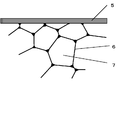
- FIG. 2 is a cross-sectional view of the base material on the first surface in which a carbonaceous film is formed on the surface of the bubbles that are closed pores according to the embodiment of the present invention.
- FIG. 3 is a cross-sectional view of the base material on the first surface in which a carbonaceous film is formed on the surface of the bubbles that have become open pores according to the embodiment of the present invention.
- 1 to 3 are applied in common to Examples 1 to 3 described below.
- Example 1 a substrate made of a carbide of phenol foam (phenolic resin foam) having a carbonaceous coating of glassy carbon is formed, and a ceramic coating made of pyrolytic carbon is formed by a CVD method. A method for producing a ceramic molded body from which a disk-shaped ceramic molded body is obtained will be described.
- Example 2 a substrate made of a carbide of phenol foam (phenolic resin foam) having a carbonaceous coating of glassy carbon is formed, and a ceramic coating made of SiC is formed by a CVD method, and the substrate is removed. A method for producing a ceramic molded body for obtaining a round pipe-shaped ceramic molded body will be described.
- Example 3 a base material made of a carbide of phenol foam (phenolic resin foam) having a carbonaceous film of pyrolytic carbon was formed, and a ceramic film made of SiC was formed by the CVD method, and the base material was removed.
- a method for manufacturing a ceramic molded body for obtaining a dish-shaped ceramic molded body having a protrusion at the center will be described.
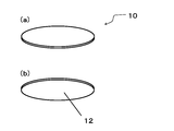
- FIG. 4A and 4B are perspective views of the ceramic molded body of Example 1 of the present invention.
- FIG. 4A is a perspective view from above
- FIG. 4B is a perspective view from below.
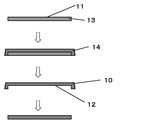
- FIG. 5 shows the manufacturing process of the ceramic molded body of Example 1 of the present invention.
- Plate-shaped phenolic foam is used as a raw material for the substrate. Since phenol foam is foamed in a mold coated with a release material, bubbles facing the surface are closed pores.
- a resin foam carbide By cutting the plate-like phenol foam into a disk shape and raising the temperature to, for example, 800 to 2000 ° C. at a rate of 10 to 100 ° C./hr in a heating furnace in a nitrogen atmosphere, a resin foam carbide can be obtained. .
- the size of the disk-shaped substrate is, for example, ⁇ 400 mm ⁇ 10 mm. Bubbles on the surface of the obtained resin foam carbide are closed pores on the bottom side and open pores on the side surface. A carbonaceous film made of glassy carbon is formed on the surface of the substrate thus obtained.
- the carbonaceous film corresponds to the second surface of the ceramic molded body and is formed on the upper bottom surface which is the first surface of the substrate. Since the side surface and the lower bottom surface of the substrate do not correspond to the second surface of the ceramic molded body, the formation of the carbonaceous film is optional.
- the carbonaceous film can be obtained by applying a phenolic resin and curing and then carbonizing.
- the phenol resin can be used after appropriately diluted with a solvent.
- the temperature of carbonization for obtaining a carbonaceous film is not particularly limited. For example, it can be obtained by treating at a temperature of 900 to 2000 ° C. Since the upper and lower bottom surfaces of the substrate are formed by a mold, the bubbles on the surface are closed pores. The carbonaceous film formed on the closed pores has a certain thickness as shown in FIG. On the other hand, since the side surface of the base material is formed by cutting, the bubbles on the surface are open pores. Since the carbonaceous film formed on the open pores is formed so as to fill the open pores and smooth the surface, the thickness is not uniform according to the location where the bubbles exist as shown in FIG. is there.
- a ceramic film made of pyrolytic carbon is formed on the substrate on which the carbonaceous film is formed by a CVD method.
- the thickness of the ceramic coating is arbitrary and can be appropriately adjusted depending on the CVD conditions and time.
- a covering in which the lower bottom surface of the substrate is exposed can be obtained.
- the base material is removed from the covering thus obtained. Since it has a simple shape, the ceramic molded body can be easily separated simply by striking with a tool. Since the ceramic molded body has an extra edge, the target disk-shaped ceramic molded body can be obtained by appropriately processing as necessary.
- FIG. 6 is a perspective view of a ceramic molded body of Example 2 of the present invention.
- FIG. 7 shows the manufacturing process of the ceramic molded body of Example 2 of the present invention.
- a plate-like phenol foam is used as a raw material for the base material and processed into a cylindrical shape.
- a resin foam carbide can be obtained.
- the size of the columnar substrate is, for example, ⁇ 50 mm ⁇ 500 mm. Since all the bubbles on the surface of the carbide of the obtained resin foam are formed by cutting, they are open pores.
- a carbonaceous film made of glassy carbon is formed on the surface of the substrate thus obtained.
- the carbonaceous film corresponds to the second surface of the ceramic molded body and is formed on the side surface of the cylinder which is the first surface of the base material. Since the bottom surfaces on both sides of the substrate do not correspond to the second surface of the ceramic molded body, the formation of the carbonaceous film is optional.
- the carbonaceous film can be obtained by applying a phenolic resin and curing and then carbonizing.
- the phenol resin can be used after appropriately diluted with a solvent.
- the temperature of carbonization for obtaining a carbonaceous film is not particularly limited. For example, it can be obtained by treating at a temperature of 800 to 2000 ° C. Since the surface of the base material is formed by cutting, bubbles on the surface are open pores. Since the carbonaceous film formed on the open pores is formed so as to fill the open pores and smooth the surface, the thickness is not uniform according to the location where the bubbles exist as shown in FIG. is there.
- a ceramic film made of SiC is formed on the base material on which the carbonaceous film is formed by a CVD method.
- the thickness of the ceramic coating is arbitrary and can be appropriately adjusted depending on the CVD conditions and time.
- the base material is removed from the covering thus obtained.
- a cutting process is simply performed using a blade, and a through hole is formed in the central portion of the base material.
- it is held in a heating furnace in an oxidizing atmosphere, and the excess base material can be completely removed.
- the condition of the heating furnace is, for example, 600 to 1500 ° C. in the air. Since both sides of the ceramic molded body have extra edges, the desired round pipe-shaped ceramic molded body can be obtained by appropriately processing as necessary.
- FIG. 8A and 8B are perspective views of a ceramic molded body of Example 3 of the present invention, in which FIG. 8A is a top perspective view and FIG. 8B is a bottom perspective view.
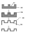
- FIG. 9 shows the manufacturing process of the ceramic molded body of Example 3 of the present invention.
- a plate-like phenol foam is used as a raw material for the base material, and is processed into a target shape having protrusions at the center and the edge.
- a resin foam carbide can be obtained.
- the size of the substrate having protrusions at the center and the edge is, for example, ⁇ 200 mm ⁇ 50 mm. Since all the bubbles on the surface of the carbide of the obtained resin foam are formed by cutting, they are open pores. A carbonaceous film made of pyrolytic carbon is formed on the surface of the substrate thus obtained. The carbonaceous film corresponds to the second surface of the ceramic molded body and is formed on the entire upper surface, which is the first surface of the substrate. Since the lower surface of the substrate does not correspond to the second surface of the ceramic molded body, the formation of the carbonaceous film is optional.
- a carbonaceous coating can be obtained by coating pyrolytic carbon in a CVD furnace.
- the CVD conditions and time are arbitrary.
- the source gas for example, methane, ethane, propane or the like can be used, and the temperature can be obtained by performing a CVD process at a temperature of 1200 to 2000 ° C., for example.
- the surface of the base material is formed by cutting, bubbles on the surface are open pores. Since the carbonaceous film formed on the open pores is formed so as to fill the open pores and smooth the surface, the thickness is not uniform according to the location where the bubbles exist as shown in FIG. is there.
- a ceramic film made of SiC is formed on the base material on which the carbonaceous film is formed by a CVD method.
- the thickness of the ceramic coating is arbitrary and can be appropriately adjusted depending on the CVD conditions and time.
- By masking the bottom surfaces on both sides of the substrate and forming a film by the CVD method it is possible to obtain a covering in which the lower surface of the substrate is exposed.
- the base material is removed from the covering thus obtained. It can be kept in a heating furnace in an oxidizing atmosphere to completely remove the excess base material.
- the condition of the heating furnace is, for example, 600 to 1500 ° C. in the air. Since the peripheral part of the ceramic molded body has an extra edge, a dish-shaped ceramic molded body having a projection at the center of the target can be obtained by appropriately processing as necessary.
Landscapes
- Chemical & Material Sciences (AREA)
- Organic Chemistry (AREA)
- Inorganic Chemistry (AREA)
- Mechanical Engineering (AREA)
- Engineering & Computer Science (AREA)
- Materials Engineering (AREA)
- Chemical Kinetics & Catalysis (AREA)
- Metallurgy (AREA)
- General Chemical & Material Sciences (AREA)
- Health & Medical Sciences (AREA)
- General Health & Medical Sciences (AREA)
- Chemical Vapour Deposition (AREA)
- Carbon And Carbon Compounds (AREA)
- Ceramic Products (AREA)
Abstract
基材にCVD法によりセラミック被膜を成膜することによりセラミック成形体を得る製造方法において、セラミック被膜にクラックを生じさせることがなく、容易に基材を除去することができるセラミック成形体の製造方法を提供する。 基材の第一表面にCVD法によりセラミック被膜を形成させたのち基材を除 去し、第一表面と対応する第二表面を有するセラミック成形体の製造方法であって、 基材は、少なくとも第一表面に炭素質被膜を有する樹脂発泡体の炭化物からなる。
Description
本発明は、セラミック成形体の製造方法に関する。
セラミック材料は、一般に高い耐熱性、硬度、強度を備え、様々な分野で使用されている。その用途としては、例えば、炉の部材、刃物、半導体製造装置用部品などが挙げられる。また、高い熱伝導を備えたセラミック材料は、プリント基板の基材、ヒートシンクとして使用されている。
セラミック材料は、各種の用途に対応するため、様々な形状に加工して用いられる。板形状、棒状、中空のパイプ形状などの単純形状の他、半導体製造装置用サセプタ、ノズル、ルツボなどの複雑形状に加工され用いられる。
特許文献1には、等径の黒鉛リングまたは黒鉛筒を同軸的に接続配置し、CVD(化学気相成長)処理によりこの接続体の周面にセラミックの被膜を形成して、管状体をなす製造方法が記載れている。さらに、CVD処理後に黒鉛を燃焼除去する管状部材の製造方法が記されている。
しかしながら、従来の方法では、黒鉛基材を燃焼除去するために高温で長時間処理しなければならない。このため目的のセラミック成形体を得るまでに長時間を要する。
また、黒鉛材料と目的とするセラミック成形体との熱膨張の違いにより、CVD法で成膜中、あるいは成膜後にセラミック被膜にクラックを生じることがある。
そもそも、従来の方法では、黒鉛基材を除去するために酸化雰囲気で処理に伴って反応してしまうセラミックを対象とすることはできない。
本発明では、基材にCVD法によりセラミック被膜を成膜することによりセラミック成形体を得る製造方法において、セラミック被膜にクラックを生じさせることがなく、容易に基材を除去することができるセラミック成形体の製造方法を提供することを目的とする。
また、黒鉛材料と目的とするセラミック成形体との熱膨張の違いにより、CVD法で成膜中、あるいは成膜後にセラミック被膜にクラックを生じることがある。
そもそも、従来の方法では、黒鉛基材を除去するために酸化雰囲気で処理に伴って反応してしまうセラミックを対象とすることはできない。
本発明では、基材にCVD法によりセラミック被膜を成膜することによりセラミック成形体を得る製造方法において、セラミック被膜にクラックを生じさせることがなく、容易に基材を除去することができるセラミック成形体の製造方法を提供することを目的とする。
前記課題を解決するための本発明のセラミック成形体の製造方法は、基材を準備する工程と、前記基材の第一表面にCVD法によりセラミック被膜を形成し被覆体を得るセラミック被膜形成工程と、前記被覆体から前記基材を除去する基材除去工程と、からなる、第一表面と対応する第二表面を有するセラミック成形体の製造方法であって、
前記基材は、少なくとも第一表面に炭素質被膜を有する樹脂発泡体の炭化物からなることを特徴とする。
前記基材は、少なくとも第一表面に炭素質被膜を有する樹脂発泡体の炭化物からなることを特徴とする。
さらに、本発明のセラミック成形体の製造方法は、次の態様が望ましい。
前記樹脂発泡体は、フェノールフォームであること。
前記基材除去工程は、前記基材を破壊すること。
前記基材除去工程は、酸化性雰囲気で前記基材を燃焼除去すること。
前記セラミック被膜は、SiCからなること。
前記記載の炭素質被膜は、熱分解炭素またはガラス状炭素であること。
本発明のセラミック成形体の製造方法によれば、基材を準備する工程と、前記基材の第一表面にCVD法によりセラミック被膜を形成し被覆体を得るセラミック被膜形成工程と、前記被覆体から前記基材を除去する基材除去工程と、からなる、第一表面と対応する第二表面を有するセラミック成形体の製造方法であって、前記基材は、少なくとも第一表面に炭素質被膜を有する樹脂発泡体の炭化物からなる。このため、樹脂発泡体の炭化物からなる基材は、容易に破壊することができ、容易に除去することができる。また基材は、少なくとも第一表面に炭素質被膜を有するので、基材の表面を平滑にすることができ、基材上に成膜されたセラミック被膜に基材が食い込みにくく、容易に除去することができる。
本明細書において、基材の片面にセラミック被膜を形成する場合であって特に断りがない場合、基材側を下、セラミック被膜側を上とする。
本明細書において、破壊とは機械的な力の作用による操作である。例えば、切削、研磨、衝撃、打撃などの作用による操作が挙げられる。
本明細書において炭化物とは、特に断りがない限り、主に炭素からなる材料を示す。このため、炭素の結晶度は特に限定されず、結晶化の進行した黒鉛から非晶質のアモルファスの炭素まで含まれる。
本明細書において、破壊とは機械的な力の作用による操作である。例えば、切削、研磨、衝撃、打撃などの作用による操作が挙げられる。
本明細書において炭化物とは、特に断りがない限り、主に炭素からなる材料を示す。このため、炭素の結晶度は特に限定されず、結晶化の進行した黒鉛から非晶質のアモルファスの炭素まで含まれる。
本発明のセラミック成形体の製造方法は、基材を準備する工程と、前記基材の第一表面にCVD法によりセラミック被膜を形成し被覆体を得るセラミック被膜形成工程と、前記被覆体から前記基材を除去する基材除去工程と、からなる、第一表面と対応する第二表面を有するセラミック成形体の製造方法であって、前記基材は、少なくとも第一表面に炭素質被膜を有する樹脂発泡体の炭化物からなる。
また、このような製造方法を経て製造されるので、セラミック成形体は、基材の一部又は全体を覆うシェル構造となる。
また、このような製造方法を経て製造されるので、セラミック成形体は、基材の一部又は全体を覆うシェル構造となる。
基材の第一表面とは、CVD法によりセラミック被膜を形成する表面である。第一表面に対応するセラミック成形体の第二表面は第一表面を反転した面である。このため、第二表面は、セラミック成形体の表面の一部分である。また、第一表面、第二表面とも平面に限定されず、曲面、複数の面の組合せ面であっても良い。
<基材形性工程>
以下に本発明の基材形成工程について説明する。基材形成工程は、発泡体準備、炭化、形状付与、炭素質被膜の形成の要素からなる。これらについて順に説明する。
以下に本発明の基材形成工程について説明する。基材形成工程は、発泡体準備、炭化、形状付与、炭素質被膜の形成の要素からなる。これらについて順に説明する。
(発泡体準備)
以下発泡体の準備について説明する。
樹脂発泡体としては、特に限定されないが、フェノールフォームをそのまま利用することができる。フェノールフォームは、フェノール樹脂を原料とし発泡させた発泡樹脂である。フェノールフォームを炭化することによって樹脂発泡体の炭化物を得ることができる。
フェノールフォームは建築材料などで断熱材として多用されているものなどを使用することができる。
この他、樹脂発泡体は、例えば次のようにして得ることができる。
以下発泡体の準備について説明する。
樹脂発泡体としては、特に限定されないが、フェノールフォームをそのまま利用することができる。フェノールフォームは、フェノール樹脂を原料とし発泡させた発泡樹脂である。フェノールフォームを炭化することによって樹脂発泡体の炭化物を得ることができる。
フェノールフォームは建築材料などで断熱材として多用されているものなどを使用することができる。
この他、樹脂発泡体は、例えば次のようにして得ることができる。
基材の原料となる樹脂は、加熱して炭素化するものであれば特に限定されない。熱硬化性樹脂、熱可塑性樹脂いずれでも利用することができる。また、熱可塑性樹脂の場合、炭素化する過程で縮合し熱硬化性樹脂に変化するものであっても良い。
熱可塑性樹脂としては、例えば、石油系ピッチ、石炭系ピッチなどのピッチが挙げられる。ピッチは、熱を加えることにより一旦軟化するが、温度が高くなるにつれてピッチどうしが縮合し、高粘度の液体を経て炭素化する。ピッチは、熱可塑性樹脂の中でも炭化収率が特に高く、本発明のセラミック成形体の製造方法の基材の原料として好適に利用することができる。
熱可塑性樹脂としては、例えば、石油系ピッチ、石炭系ピッチなどのピッチが挙げられる。ピッチは、熱を加えることにより一旦軟化するが、温度が高くなるにつれてピッチどうしが縮合し、高粘度の液体を経て炭素化する。ピッチは、熱可塑性樹脂の中でも炭化収率が特に高く、本発明のセラミック成形体の製造方法の基材の原料として好適に利用することができる。
基材の原料となる熱硬化性樹脂は、一旦硬化したものは網目状の高分子からなり、熱を加えても可塑化することがないので流動することなく炭素化することができる。このため炭化収率が高く、フェノール樹脂、フラン樹脂、コプナ樹脂、ユリア樹脂、メラミン樹脂、エポキシ樹脂、不飽和ポリエステル樹脂などが好適に利用できる。
樹脂を発泡させ樹脂発泡体を得る方法は、特に限定されない。例えば、ガス、水分などを生成する縮合あるいは重合反応する樹脂であれば、生成するガス、水分を利用して加熱により発泡させることができる。具体的には、反応時に急速にガスまたは水蒸気を発生させ一気に樹脂を膨張させる。熱硬化性樹脂であれば、徐々に粘度が高くなり硬化するので発泡した状態を雰囲気温度に関わらず維持することができる。熱可塑性樹脂であれば、温度を下げたり、長時間放置すると気泡が消滅するので、気泡を生成した状態を保ちながら一気に炭化させることにより、樹脂発泡体の炭化物を形成することができる。
また、縮合あるいは重合に際し反応ガス、水分などを生成しない場合、十分に発泡しない場合には、例えば気化温度の低い物質を原料に混合し、加熱時の蒸発又は昇華によって発泡を補助することができる。気化温度の低い物質とは、沸点の低い液体、固体ではあるが液化しその液体の沸点が低い固体、昇華点の低い固体などが挙げられる。具体的には水、アルコール、フロン系化合物、ヘキサンなどの炭化水素が挙げられる。
また、減圧雰囲気下で発生した気泡を膨張させることによって発泡を補助することもできる。
また、減圧雰囲気下で発生した気泡を膨張させることによって発泡を補助することもできる。
(炭化)
次に、樹脂発泡体の炭化の要素について説明する。
樹脂発泡体の炭化物は、不活性雰囲気または還元性雰囲気で樹脂発泡体を加熱させ炭化物を得ることができる。加熱の方法、温度は特に限定されない。フェノールフォームなど熱硬化性樹脂を使用する場合は、気泡を含んだ状態で硬化しているので、加熱するだけで炭化物を得ることができる。尚、樹脂から発生する分解ガスがゆっくり拡散するよう昇温速度を遅くすることにより、独立気泡を含有する樹脂発泡体の炭化物を得ることができる。独立気泡を含有する樹脂発泡体の炭化物は、個々の気泡が壁で覆われているので後のCVD処理が行われるまで変形することなく形状を保持しやすくすることができる。
次に、樹脂発泡体の炭化の要素について説明する。
樹脂発泡体の炭化物は、不活性雰囲気または還元性雰囲気で樹脂発泡体を加熱させ炭化物を得ることができる。加熱の方法、温度は特に限定されない。フェノールフォームなど熱硬化性樹脂を使用する場合は、気泡を含んだ状態で硬化しているので、加熱するだけで炭化物を得ることができる。尚、樹脂から発生する分解ガスがゆっくり拡散するよう昇温速度を遅くすることにより、独立気泡を含有する樹脂発泡体の炭化物を得ることができる。独立気泡を含有する樹脂発泡体の炭化物は、個々の気泡が壁で覆われているので後のCVD処理が行われるまで変形することなく形状を保持しやすくすることができる。
本発明のセラミック成形体の製造方法に用いる樹脂発泡体の炭化物の気泡の直径は特に限定されない。例えば平均気泡直径が5.0~600μmである樹脂発泡体の炭化物を利用することができる。樹脂発泡体の炭化物の気泡の直径が600μm以下であると、第一表面に面する気泡が破壊しても、成膜で得られるセラミック被膜が気泡を塞ぎやすく、得られるセラミック成形体の第二の表面に突起をできにくくすることができる。樹脂発泡体の炭化物の気泡の直径が5.0μm以上であると、後の基材除去工程で破壊する薄壁が少ないので容易に基材を除去することができる。これは、反応性ガスを用いて基材を除去する場合に得に効果がある。
平均気泡直径とは、樹脂発泡体の炭化物の断面の単位面積Sと露出する気泡の数nから計算することができる。平均気泡体積をv、平均気泡直径をdとすると
v=S2/n2 (式1)
d=(3v/4π)1/3 (式2)
として、算出することができる。
また、本発明において、気泡は通常歪な形状をしているので、同一体積の球の直径をその気泡の直径と定義する。
平均気泡直径とは、樹脂発泡体の炭化物の断面の単位面積Sと露出する気泡の数nから計算することができる。平均気泡体積をv、平均気泡直径をdとすると
v=S2/n2 (式1)
d=(3v/4π)1/3 (式2)
として、算出することができる。
また、本発明において、気泡は通常歪な形状をしているので、同一体積の球の直径をその気泡の直径と定義する。
(形状付与)
以下形状付与の要素について説明する。
本発明のセラミック成形体の製造方法において基材はどのように形状を付与してもよい。
形状付与は
(1)樹脂発泡体の製造と同時、
(2)炭化前、
(3)炭化後
のいずれでも行うことができる。
樹脂発泡体の製造と同時(1)に形状を付与する場合には、樹脂発泡体を型の中で発泡させ、炭化して目的の基材を得る。樹脂発泡体は、強度が弱いので型の内面は離型しやすいように充分に離型剤を塗布しておくことが望ましい。
樹脂発泡体の製造と同時に形状を付与する場合には、樹脂発泡体の表面に位置する気泡は閉気孔が得られやすい。型を用いて樹脂発泡体の製造と同時に目的の形状を得る方法では、同一の形状の樹脂発泡体が簡単に得られるので、大量生産に適している。
また、樹脂発泡体を製造した後には炭化前(2)炭化後(3)いずれでも切削加工などで目的の形状を得ることができる。切削加工で目的の形状を得る場合には、表面に位置する気泡は開気孔となる。炭化後(3)に形状を付与する場合、樹脂発泡体の炭化に伴う収縮が治まっているので寸法精度が高い利点がある。
以下形状付与の要素について説明する。
本発明のセラミック成形体の製造方法において基材はどのように形状を付与してもよい。
形状付与は
(1)樹脂発泡体の製造と同時、
(2)炭化前、
(3)炭化後
のいずれでも行うことができる。
樹脂発泡体の製造と同時(1)に形状を付与する場合には、樹脂発泡体を型の中で発泡させ、炭化して目的の基材を得る。樹脂発泡体は、強度が弱いので型の内面は離型しやすいように充分に離型剤を塗布しておくことが望ましい。
樹脂発泡体の製造と同時に形状を付与する場合には、樹脂発泡体の表面に位置する気泡は閉気孔が得られやすい。型を用いて樹脂発泡体の製造と同時に目的の形状を得る方法では、同一の形状の樹脂発泡体が簡単に得られるので、大量生産に適している。
また、樹脂発泡体を製造した後には炭化前(2)炭化後(3)いずれでも切削加工などで目的の形状を得ることができる。切削加工で目的の形状を得る場合には、表面に位置する気泡は開気孔となる。炭化後(3)に形状を付与する場合、樹脂発泡体の炭化に伴う収縮が治まっているので寸法精度が高い利点がある。
(炭素質被膜の形成)
以下、炭素質被膜の形成について説明する。
本発明のセラミック成形体の製造方法において、樹脂発泡体の炭化物の少なくとも第一表面には、炭素質被膜が形成されている。炭素質被膜としては、熱分解炭素、ガラス状炭素が挙げられる。
以下、炭素質被膜の形成について説明する。
本発明のセラミック成形体の製造方法において、樹脂発泡体の炭化物の少なくとも第一表面には、炭素質被膜が形成されている。炭素質被膜としては、熱分解炭素、ガラス状炭素が挙げられる。
熱分解炭素からなる炭素質皮膜は、樹脂発泡体の炭化物に炭化水素ガスを用いたCVD法によって形成することができる。
またガラス状炭素からなる炭素質被膜は、樹脂発泡体の炭化物に例えばフェノール樹脂などのガラス状炭素前駆体を塗布し炭化することによって得ることができる。
またガラス状炭素からなる炭素質被膜は、樹脂発泡体の炭化物に例えばフェノール樹脂などのガラス状炭素前駆体を塗布し炭化することによって得ることができる。
炭素質被膜は、樹脂発泡体の隣合う気泡どうしを区切る炭化物の薄壁、あるいは基材表面に位置する気泡表面の炭化物の薄壁とは次の点で異なる。樹脂発泡体の隣合う気泡どうしを区切る炭化物の薄壁、あるいは基材表面に位置する気泡表面の炭化物の薄壁は、互いに厚さが均等になる様に樹脂が分配されるので、いずれの位置でもほぼ同等の厚さである。これに対し、炭素質被膜は、樹脂発泡体が炭化した後に基材表面の気泡の薄壁を覆うように形成される。このため、炭素質被膜は樹脂発泡体の隣合う気泡どうしを区切る炭化物の薄壁、あるいは基材表面に位置する気泡表面の炭化物の薄壁のいずれよりも厚く形成される。
本発明のセラミック成形体の製造方法において炭素質被膜は、樹脂発泡体の炭化物の気泡の凹凸とは無関係に滑らかな表面を形成するので、基材表面に形成されるセラミック被膜に滑らかな表面状態を付与することができ、得られるセラミック成形体の第二表面が平滑なものとなる。さらに基材の第一表面にセラミック被膜が食い込みにくく、基材除去工程で容易に基材を除去することができる。
<セラミック被膜形成工程>
以下に本発明のセラミック被膜形成工程について説明する。
本発明のセラミック成形体の製造方法はこうして得られた基材の表面にCVD法によりセラミック被膜を形成する。CVD法で形成するセラミック被膜は、例えばSiC、BN、熱分解炭素、TaCなどが利用できる。目的とするセラミック成形体の材質に応じて適宜選択することができる。中でもSiCは、厚いセラミック被膜が得られやすく、高い強度、耐蝕性を有しているので好適に利用することができる。
以下に本発明のセラミック被膜形成工程について説明する。
本発明のセラミック成形体の製造方法はこうして得られた基材の表面にCVD法によりセラミック被膜を形成する。CVD法で形成するセラミック被膜は、例えばSiC、BN、熱分解炭素、TaCなどが利用できる。目的とするセラミック成形体の材質に応じて適宜選択することができる。中でもSiCは、厚いセラミック被膜が得られやすく、高い強度、耐蝕性を有しているので好適に利用することができる。
本発明のセラミック成形体の製造方法において、CVDの方法は特に限定されない。原料ガス、キャリアガス、圧力、温度、時間は適宜選択することができる。
例えば、SiCからなるセラミック成形体を得る場合には、原料ガスとして、MTS(メチルトリクロロシラン)、キャリアガスとして水素を用い、1000~1500℃でセラミック被膜を得ることができる。CVDの際に、後の基材除去工程で基材を除去しやすいように一部基材表面を残すようマスキングしCVD処理をしても良い。このように処理するとCVD処理後に基材の一部表面がセラミック被膜に覆われることなく露出しているので、基材の露出部分から基材を除去することができる。また、マスキングをすることなくセラミック被膜を形成した場合には、CVD後に基材の一部露出させ基材を除去しても良い。CVD後に基材の一部の露出はダイヤモンドカッタ、レーザ加工機、ウォータジェットなどの加工機を用いて行うことができる。
例えば、SiCからなるセラミック成形体を得る場合には、原料ガスとして、MTS(メチルトリクロロシラン)、キャリアガスとして水素を用い、1000~1500℃でセラミック被膜を得ることができる。CVDの際に、後の基材除去工程で基材を除去しやすいように一部基材表面を残すようマスキングしCVD処理をしても良い。このように処理するとCVD処理後に基材の一部表面がセラミック被膜に覆われることなく露出しているので、基材の露出部分から基材を除去することができる。また、マスキングをすることなくセラミック被膜を形成した場合には、CVD後に基材の一部露出させ基材を除去しても良い。CVD後に基材の一部の露出はダイヤモンドカッタ、レーザ加工機、ウォータジェットなどの加工機を用いて行うことができる。
基材の第一表面に形成される炭素質被膜が熱分解炭素であり、熱分解炭素よりなるセラミック成形体を得る場合、熱分解炭素の上に熱分解炭素を成膜させることになるが、もともと熱分解炭素どうしは接合力が小さいので、基材側の熱分解炭素からなる炭素質被膜は、基材側を破壊することにより容易に除去することができる。また、基材除去工程の条件を適宜調整することにより、反応性ガスの雰囲気下で加熱することにより、セラミック成形体側の反応を最小限に抑えながら基材を除去することができる。このため、基材の第一表面に形成される炭素質被膜が熱分解炭素であり、熱分解炭素よりなるセラミック成形体を得る組合せも実施することができる。
<基材除去工程>
以下に本発明の基材除去工程について説明する。
樹脂発泡体の炭化物とは、多数の気泡が形成された樹脂を炭化し得られたものであって、隣合う気泡どうしは炭化物の薄壁で区切られている。薄壁は薄い膜よりなり、容易に破壊することができる。セラミック被膜が形成された被覆体から基材を除去する方法は特に限定されない。セラミック被膜が形成された被覆体から基材を除去する方法としては、破壊する方法、反応性ガスによる反応による方法などが挙げられる。また基材を破壊した後に反応性ガスによって反応させるなどこれらを併用しても良い。
以下に本発明の基材除去工程について説明する。
樹脂発泡体の炭化物とは、多数の気泡が形成された樹脂を炭化し得られたものであって、隣合う気泡どうしは炭化物の薄壁で区切られている。薄壁は薄い膜よりなり、容易に破壊することができる。セラミック被膜が形成された被覆体から基材を除去する方法は特に限定されない。セラミック被膜が形成された被覆体から基材を除去する方法としては、破壊する方法、反応性ガスによる反応による方法などが挙げられる。また基材を破壊した後に反応性ガスによって反応させるなどこれらを併用しても良い。
基材を破壊により除去する場合には、切削、研磨、衝撃、工具による打撃などで破壊することができる。いずれの場合にも、炭化物の気泡の境界の薄壁部分から容易に破壊することができる。
また、基材に含まれる気泡の境界は薄壁よりなるので、反応性ガスの雰囲気下で加熱することにより、容易に薄壁を除去することができる。具体的には、反応性ガスとして酸素、空気、水蒸気などが挙げられる。これらは酸化性ガスであり、反応によって、CO、CO2を生成する。これらの方法は、酸化反応を用いた燃焼除去である。また、異なる種類の反応性ガスとして水素、アンモニアなどが挙げられる。これらは還元性ガスであり、反応によって炭化水素を生成する。
また、基材に含まれる気泡の境界は薄壁よりなるので、反応性ガスの雰囲気下で加熱することにより、容易に薄壁を除去することができる。具体的には、反応性ガスとして酸素、空気、水蒸気などが挙げられる。これらは酸化性ガスであり、反応によって、CO、CO2を生成する。これらの方法は、酸化反応を用いた燃焼除去である。また、異なる種類の反応性ガスとして水素、アンモニアなどが挙げられる。これらは還元性ガスであり、反応によって炭化水素を生成する。
酸化性ガスを用いた発泡性樹脂の炭化物との酸化反応は、容易に進行させることができる。一方、セラミック成形体の素材の種類によってはセラミック成形体を傷めにくいよう、還元性ガスを用いて、還元反応によって基材を除去しても良い。酸化性ガスを用いた酸化反応で基材を除去する場合は、例えば400℃以上で保持することにより基材を除去することができる。さらに速やかに基材の除去するためには600℃以上に保持することが好ましい。
還元性ガスを用いた還元反応では、基材を構成する発泡性樹脂の炭化物が、水素と結合しメタンなどの炭化水素を形成する。還元性ガスを用いた還元反応で基材を除去する場合は、例えば800℃以上で保持し反応させることにより基材を除去することができる。さらに速やかに基材の除去するためには1000℃以上に保持し反応させることが好ましい。
還元性ガスを用いた還元反応では、基材を構成する発泡性樹脂の炭化物が、水素と結合しメタンなどの炭化水素を形成する。還元性ガスを用いた還元反応で基材を除去する場合は、例えば800℃以上で保持し反応させることにより基材を除去することができる。さらに速やかに基材の除去するためには1000℃以上に保持し反応させることが好ましい。
基材を除去することによりセラミック成形体を得ることができる。得られたセラミック成形体は、必要に応じて後加工を加えても良い。
なお、最終的にセラミック成形体が切削加工される場合には、基材の第一表面は最終的に得られるセラミック成形体の表面に対応する面が定義される。基材が除去されたセラミック被膜のうち、切削加工され取り除かれる部分はどのような面であっても、最終的なセラミック成形体の表面に影響を与えることはない。このため、基材の第一表面は最終的に得られるセラミック成形体の表面に対応する面に限定され、その周辺部分には炭素質被膜を有していなくても実害がないからである。
以下に本発明の実施例1、実施例2、実施例3について図面を用いて具体的に説明する。
図1は、本発明のセラミック成形体の製造方法の製造工程を示す。図2は、本発明の実施の形態の閉気孔となった気泡の表面に炭素質被膜が形成された第一表面における基材の断面図である。図3は、本発明の実施の形態の開気孔となった気泡の表面に炭素質被膜が形成された第一表面における基材の断面図である。図1~3は以下説明する実施例1~3に共通して適用される。
図1は、本発明のセラミック成形体の製造方法の製造工程を示す。図2は、本発明の実施の形態の閉気孔となった気泡の表面に炭素質被膜が形成された第一表面における基材の断面図である。図3は、本発明の実施の形態の開気孔となった気泡の表面に炭素質被膜が形成された第一表面における基材の断面図である。図1~3は以下説明する実施例1~3に共通して適用される。
実施例1では、ガラス状炭素の炭素質被膜を有するフェノールフォーム(フェノール樹脂の発泡体)の炭化物からなる基材を形成し、さらに熱分解炭素からなるセラミック被膜をCVD法により形成し、基材を除去し円盤状のセラミック成形体を得るセラミック成形体の製造方法について説明する。
実施例2では、ガラス状炭素の炭素質被膜を有するフェノールフォーム(フェノール樹脂の発泡体)の炭化物からなる基材を形成し、さらにSiCからなるセラミック被膜をCVD法により形成し、基材を除去し丸パイプ状のセラミック成形体を得るセラミック成形体の製造方法について説明する。
実施例3では、熱分解炭素の炭素質被膜を有するフェノールフォーム(フェノール樹脂の発泡体)の炭化物からなる基材を形成し、さらにSiCからなるセラミック被膜をCVD法により形成し、基材を除去し中央に突起を有する皿状のセラミック成形体を得るセラミック成形体の製造方法について説明する。

実施例2では、ガラス状炭素の炭素質被膜を有するフェノールフォーム(フェノール樹脂の発泡体)の炭化物からなる基材を形成し、さらにSiCからなるセラミック被膜をCVD法により形成し、基材を除去し丸パイプ状のセラミック成形体を得るセラミック成形体の製造方法について説明する。
実施例3では、熱分解炭素の炭素質被膜を有するフェノールフォーム(フェノール樹脂の発泡体)の炭化物からなる基材を形成し、さらにSiCからなるセラミック被膜をCVD法により形成し、基材を除去し中央に突起を有する皿状のセラミック成形体を得るセラミック成形体の製造方法について説明する。
<実施例1>
図4は本発明の実施例1のセラミック成形体の斜視図であり、(a)は上方からの斜視図、(b)は下方からの斜視図を示す。図5は本発明の実施例1のセラミック成形体の製造工程を示す。
図4は本発明の実施例1のセラミック成形体の斜視図であり、(a)は上方からの斜視図、(b)は下方からの斜視図を示す。図5は本発明の実施例1のセラミック成形体の製造工程を示す。
基材の原材料として板状のフェノールフォームを使用する。フェノールフォームは、離型材を塗布した型の中で発泡しているので表面に面する気泡は閉気孔となっている。板状のフェノールフォームを円盤状に切断し、窒素雰囲気の加熱炉で、例えば10~100℃/hrの速度で800~2000℃まで昇温させることにより、樹脂発泡体の炭化物を得ることができる。円盤状の基材のサイズは例えばφ400mm×10mmである。得られた樹脂発泡体の炭化物の表面の気泡は、底面側は閉気孔、側面側は開気孔となっている。
こうして得られた基材の表面にガラス状炭素からなる炭素質被膜を形成する。炭素質被膜はセラミック成形体の第二表面に対応し基材の第一表面である上側底面に形成される。基材の側面及び下側底面はセラミック成形体の第二表面に対応しないので、炭素質被膜の形成は任意である。
こうして得られた基材の表面にガラス状炭素からなる炭素質被膜を形成する。炭素質被膜はセラミック成形体の第二表面に対応し基材の第一表面である上側底面に形成される。基材の側面及び下側底面はセラミック成形体の第二表面に対応しないので、炭素質被膜の形成は任意である。
炭素質被膜は、フェノール樹脂を塗布し、硬化した後に炭化することによって得ることができる。フェノール樹脂は、溶媒で適宜希釈して用いることができる。炭素質被膜を得るための炭化の温度は特に限定されない。例えば900~2000℃の温度で処理することによって得ることができる。
基材の上側及び下側底面は、型によって面が形成されているので、表面の気泡は閉気孔となっている。閉気孔の上に形成された炭素質被膜は図2に示されるように一定の厚みを有している。一方、基材の側面は、切削加工によって面が形成されているので、表面の気泡は開気孔となっている。開気孔の上に形成された炭素質被膜は、開気孔を充填し表面が平滑になるように形成されるので、図3に示されるように厚みは気泡の存在する箇所に応じて不均一である。
基材の上側及び下側底面は、型によって面が形成されているので、表面の気泡は閉気孔となっている。閉気孔の上に形成された炭素質被膜は図2に示されるように一定の厚みを有している。一方、基材の側面は、切削加工によって面が形成されているので、表面の気泡は開気孔となっている。開気孔の上に形成された炭素質被膜は、開気孔を充填し表面が平滑になるように形成されるので、図3に示されるように厚みは気泡の存在する箇所に応じて不均一である。
炭素質被膜の形成された基材に、熱分解炭素からなるセラミック被膜をCVD法により形成する。セラミック被膜の厚みは任意であり、CVDの条件、時間により適宜調整することができる。基材の下側底面を台座に密着させ、CVD法により成膜することにより、基材の下側底面が露出した被覆体を得ることができる。
こうして得られた被覆体から、基材を除去する。単純形状であるので工具を用いて打撃するだけで容易にセラミック成形体を分離することができる。セラミック成形体には余分な縁を有しているので、必要に応じて適宜加工することにより、目的の円盤形状のセラミック成形体を得ることができる。
こうして得られた被覆体から、基材を除去する。単純形状であるので工具を用いて打撃するだけで容易にセラミック成形体を分離することができる。セラミック成形体には余分な縁を有しているので、必要に応じて適宜加工することにより、目的の円盤形状のセラミック成形体を得ることができる。
<実施例2>
図6は本発明の実施例2のセラミック成形体の斜視図である。図7は本発明の実施例2のセラミック成形体の製造工程を示す。
基材の原材料として板状のフェノールフォームを使用し、円柱形状に加工する。加工されたフェノールフォームを窒素雰囲気の加熱炉で、例えば10~100℃/hrの速度で800~2000℃まで昇温させることにより、樹脂発泡体の炭化物を得ることができる。円柱状の基材のサイズは例えばφ50mm×500mmである。得られた樹脂発泡体の炭化物の表面の気泡は、すべて切削加工で形成されているので開気孔となっている。
こうして得られた基材の表面にガラス状炭素からなる炭素質被膜を形成する。炭素質被膜はセラミック成形体の第二表面に対応し基材の第一表面である円柱の側面に形成される。基材の両側の底面はセラミック成形体の第二表面に対応しないので、炭素質被膜の形成は任意である。
図6は本発明の実施例2のセラミック成形体の斜視図である。図7は本発明の実施例2のセラミック成形体の製造工程を示す。
基材の原材料として板状のフェノールフォームを使用し、円柱形状に加工する。加工されたフェノールフォームを窒素雰囲気の加熱炉で、例えば10~100℃/hrの速度で800~2000℃まで昇温させることにより、樹脂発泡体の炭化物を得ることができる。円柱状の基材のサイズは例えばφ50mm×500mmである。得られた樹脂発泡体の炭化物の表面の気泡は、すべて切削加工で形成されているので開気孔となっている。
こうして得られた基材の表面にガラス状炭素からなる炭素質被膜を形成する。炭素質被膜はセラミック成形体の第二表面に対応し基材の第一表面である円柱の側面に形成される。基材の両側の底面はセラミック成形体の第二表面に対応しないので、炭素質被膜の形成は任意である。
炭素質被膜は、フェノール樹脂を塗布し、硬化した後に炭化することによって得ることができる。フェノール樹脂は、溶媒で適宜希釈して用いることができる。炭素質被膜を得るための炭化の温度は特に限定されない。例えば800~2000℃の温度で処理することによって得ることができる。
基材の表面は、切削加工によって面が形成されているので、表面の気泡は開気孔となっている。開気孔の上に形成された炭素質被膜は、開気孔を充填し表面が平滑になるように形成されるので、図3に示されるように厚みは気泡の存在する箇所に応じて不均一である。
炭素質被膜の形成された基材に、SiCからなるセラミック被膜をCVD法により形成する。セラミック被膜の厚みは任意であり、CVDの条件、時間により適宜調整することができる。基材の両側底面をマスキングし、CVD法により成膜することにより、基材の両側底面が露出した被覆体を得ることができる。
こうして得られた被覆体から、基材を除去する。後の燃焼除去を容易に行うために単純まず刃物を用いて切削加工し、基材の中央部分に貫通孔をあける。次に酸化雰囲気の加熱炉中で保持し、余分な基材を完全に除去することができる。加熱炉の条件は、例えば空気中の600~1500℃である。
セラミック成形体の両側端には余分な縁を有しているので、必要に応じて適宜加工することにより、目的の丸パイプ形状のセラミック成形体を得ることができる。
基材の表面は、切削加工によって面が形成されているので、表面の気泡は開気孔となっている。開気孔の上に形成された炭素質被膜は、開気孔を充填し表面が平滑になるように形成されるので、図3に示されるように厚みは気泡の存在する箇所に応じて不均一である。
炭素質被膜の形成された基材に、SiCからなるセラミック被膜をCVD法により形成する。セラミック被膜の厚みは任意であり、CVDの条件、時間により適宜調整することができる。基材の両側底面をマスキングし、CVD法により成膜することにより、基材の両側底面が露出した被覆体を得ることができる。
こうして得られた被覆体から、基材を除去する。後の燃焼除去を容易に行うために単純まず刃物を用いて切削加工し、基材の中央部分に貫通孔をあける。次に酸化雰囲気の加熱炉中で保持し、余分な基材を完全に除去することができる。加熱炉の条件は、例えば空気中の600~1500℃である。
セラミック成形体の両側端には余分な縁を有しているので、必要に応じて適宜加工することにより、目的の丸パイプ形状のセラミック成形体を得ることができる。
<実施例3>
図8は本発明の実施例3のセラミック成形体の斜視図であり、(a)は上面の斜視図、(b)は下面の斜視図である。図9は本発明の実施例3のセラミック成形体の製造工程を示す。
基材の原材料として板状のフェノールフォームを使用し、中央部及び縁に突起のある目的形状に加工する。加工されたフェノールフォームを窒素雰囲気の加熱炉で、例えば10~100℃/hrの速度で800~2000℃まで昇温させることにより、樹脂発泡体の炭化物を得ることができる。中央部及び縁に突起のある基材のサイズは例えばφ200mm×50mmである。得られた樹脂発泡体の炭化物の表面の気泡は、すべて切削加工で形成されているので開気孔となっている。
こうして得られた基材の表面に熱分解炭素からなる炭素質被膜を形成する。炭素質被膜はセラミック成形体の第二表面に対応し基材の第一表面である上側全面に形成される。基材の下側面はセラミック成形体の第二表面に対応しないので、炭素質被膜の形成は任意である。
図8は本発明の実施例3のセラミック成形体の斜視図であり、(a)は上面の斜視図、(b)は下面の斜視図である。図9は本発明の実施例3のセラミック成形体の製造工程を示す。
基材の原材料として板状のフェノールフォームを使用し、中央部及び縁に突起のある目的形状に加工する。加工されたフェノールフォームを窒素雰囲気の加熱炉で、例えば10~100℃/hrの速度で800~2000℃まで昇温させることにより、樹脂発泡体の炭化物を得ることができる。中央部及び縁に突起のある基材のサイズは例えばφ200mm×50mmである。得られた樹脂発泡体の炭化物の表面の気泡は、すべて切削加工で形成されているので開気孔となっている。
こうして得られた基材の表面に熱分解炭素からなる炭素質被膜を形成する。炭素質被膜はセラミック成形体の第二表面に対応し基材の第一表面である上側全面に形成される。基材の下側面はセラミック成形体の第二表面に対応しないので、炭素質被膜の形成は任意である。
炭素質被膜は、CVD炉中で熱分解炭素を被覆することによって得ることができる。CVDの条件、時間は任意である。原料ガスは、例えばメタン、エタン、プロパンなどが利用でき、温度は例えば1200~2000℃の温度でCVD処理することによって得ることができる。
基材の表面は、切削加工によって面が形成されているので、表面の気泡は開気孔となっている。開気孔の上に形成された炭素質被膜は、開気孔を充填し表面が平滑になるように形成されるので、図3に示されるように厚みは気泡の存在する箇所に応じて不均一である。
炭素質被膜の形成された基材に、SiCからなるセラミック被膜をCVD法により形成する。セラミック被膜の厚みは任意であり、CVDの条件、時間により適宜調整することができる。基材の両側底面をマスキングし、CVD法により成膜することにより、基材の下側面が露出した被覆体を得ることができる。
こうして得られた被覆体から、基材を除去する。酸化雰囲気の加熱炉中で保持し、余分な基材を完全に除去することができる。加熱炉の条件は、例えば空気中の600~1500℃である。
セラミック成形体の周辺部には余分な縁を有しているので、必要に応じて適宜加工することにより、目的の中央に突起を有する皿状のセラミック成形体を得ることができる。
基材の表面は、切削加工によって面が形成されているので、表面の気泡は開気孔となっている。開気孔の上に形成された炭素質被膜は、開気孔を充填し表面が平滑になるように形成されるので、図3に示されるように厚みは気泡の存在する箇所に応じて不均一である。
炭素質被膜の形成された基材に、SiCからなるセラミック被膜をCVD法により形成する。セラミック被膜の厚みは任意であり、CVDの条件、時間により適宜調整することができる。基材の両側底面をマスキングし、CVD法により成膜することにより、基材の下側面が露出した被覆体を得ることができる。
こうして得られた被覆体から、基材を除去する。酸化雰囲気の加熱炉中で保持し、余分な基材を完全に除去することができる。加熱炉の条件は、例えば空気中の600~1500℃である。
セラミック成形体の周辺部には余分な縁を有しているので、必要に応じて適宜加工することにより、目的の中央に突起を有する皿状のセラミック成形体を得ることができる。
10、20、30 セラミック成形体
11、21、31 第一表面
12、22、32 第二表面
13、23、33 基材
14、24、34 セラミック被膜
5 炭素質被膜
6 薄壁
7 気泡
11、21、31 第一表面
12、22、32 第二表面
13、23、33 基材
14、24、34 セラミック被膜
5 炭素質被膜
6 薄壁
7 気泡
Claims (6)
- 基材を準備する工程と、前記基材の第一表面にCVD法によりセラミック被膜を形成し被覆体を得るセラミック被膜形成工程と、前記被覆体から前記基材を除去する基材除去工程と、からなる、第一表面と対応する第二表面を有するセラミック成形体の製造方法であって、
前記基材は、少なくとも第一表面に炭素質被膜を有する樹脂発泡体の炭化物からなることを特徴とするセラミック成形体の製造方法。 - 前記樹脂発泡体はフェノールフォームであることを特徴とする請求項1に記載のセラミック成形体の製造方法。
- 前記基材除去工程は、前記基材を破壊することを特徴とする請求項1または2に記載のセラミック成形体の製造方法。
- 前記基材除去工程は、酸化性雰囲気で前記基材を燃焼除去すること含むことを特徴とする請求項1~3のいずれか一項に記載のセラミック成形体の製造方法。
- 前記セラミック被膜は、SiCからなることを特徴とする請求項1~4のいずれか一項に記載のセラミック成形体の製造方法。
- 前記記載の炭素質被膜は、熱分解炭素またはガラス状炭素であることを特徴とする請求項1~5のいずれか一項に記載のセラミック成形体の製造方法。
Applications Claiming Priority (2)
| Application Number | Priority Date | Filing Date | Title |
|---|---|---|---|
| JP2013-179093 | 2013-08-30 | ||
| JP2013179093A JP6175315B2 (ja) | 2013-08-30 | 2013-08-30 | セラミック成形体の製造方法 |
Publications (1)
| Publication Number | Publication Date |
|---|---|
| WO2015029918A1 true WO2015029918A1 (ja) | 2015-03-05 |
Family
ID=52586476
Family Applications (1)
| Application Number | Title | Priority Date | Filing Date |
|---|---|---|---|
| PCT/JP2014/072087 Ceased WO2015029918A1 (ja) | 2013-08-30 | 2014-08-25 | セラミック成形体の製造方法 |
Country Status (2)
| Country | Link |
|---|---|
| JP (1) | JP6175315B2 (ja) |
| WO (1) | WO2015029918A1 (ja) |
Cited By (1)
| Publication number | Priority date | Publication date | Assignee | Title |
|---|---|---|---|---|
| JP2025523559A (ja) * | 2022-07-04 | 2025-07-23 | トーカイ カーボン コリア カンパニー.,リミテッド | 半導体製造装置用部品及びその製造方法 |
Families Citing this family (2)
| Publication number | Priority date | Publication date | Assignee | Title |
|---|---|---|---|---|
| JP6752914B2 (ja) * | 2019-02-28 | 2020-09-09 | 株式会社フェローテックマテリアルテクノロジーズ | 膜構造体製造方法および膜構造体 |
| KR102663768B1 (ko) * | 2022-02-07 | 2024-05-03 | (주)코멕스카본 | 자동차 디스플레이용 곡면 커버유리를 성형하기 위한 그라파이트 금형 가공방법 |
Citations (3)
| Publication number | Priority date | Publication date | Assignee | Title |
|---|---|---|---|---|
| JPS62297280A (ja) * | 1986-06-16 | 1987-12-24 | イビデン株式会社 | 炭素系発泡断熱成形体およびその製造方法 |
| JPH10226574A (ja) * | 1997-02-17 | 1998-08-25 | Toyo Tanso Kk | 化学気相蒸着炭化ケイ素材の製造方法 |
| JP2009019238A (ja) * | 2007-07-12 | 2009-01-29 | Tokai Carbon Co Ltd | CVD−SiC単体膜の製造方法 |
-
2013
- 2013-08-30 JP JP2013179093A patent/JP6175315B2/ja active Active
-
2014
- 2014-08-25 WO PCT/JP2014/072087 patent/WO2015029918A1/ja not_active Ceased
Patent Citations (3)
| Publication number | Priority date | Publication date | Assignee | Title |
|---|---|---|---|---|
| JPS62297280A (ja) * | 1986-06-16 | 1987-12-24 | イビデン株式会社 | 炭素系発泡断熱成形体およびその製造方法 |
| JPH10226574A (ja) * | 1997-02-17 | 1998-08-25 | Toyo Tanso Kk | 化学気相蒸着炭化ケイ素材の製造方法 |
| JP2009019238A (ja) * | 2007-07-12 | 2009-01-29 | Tokai Carbon Co Ltd | CVD−SiC単体膜の製造方法 |
Cited By (1)
| Publication number | Priority date | Publication date | Assignee | Title |
|---|---|---|---|---|
| JP2025523559A (ja) * | 2022-07-04 | 2025-07-23 | トーカイ カーボン コリア カンパニー.,リミテッド | 半導体製造装置用部品及びその製造方法 |
Also Published As
| Publication number | Publication date |
|---|---|
| JP2015048490A (ja) | 2015-03-16 |
| JP6175315B2 (ja) | 2017-08-02 |
Similar Documents
| Publication | Publication Date | Title |
|---|---|---|
| JP4409834B2 (ja) | プロセス減圧により誘導された炭素発泡体の製造方法 | |
| US10609810B2 (en) | Method for producing heat-dissipating sheet having high thermal conductivity | |
| JP6651754B2 (ja) | 反応焼結炭化ケイ素部材の製造方法 | |
| KR100555074B1 (ko) | 피치 계 탄소 폼 및 복합체 | |
| US6833012B2 (en) | Petroleum pitch-based carbon foam | |
| US9631130B2 (en) | Heat-dissipating sheet having high thermal conductivity and its production method | |
| JP2017515771A (ja) | 炭素/炭素複合材料の製造方法 | |
| JP6175315B2 (ja) | セラミック成形体の製造方法 | |
| US20060141154A1 (en) | Method for treating the surface of a part made of a heat-structured composite material and use thereof in brazing parts made of a heat-structured composite material | |
| JP5673034B2 (ja) | タンタル容器の浸炭処理方法 | |
| CN110062951B (zh) | 半导体制造用部件、包括复合体涂层的半导体制造用部件及其制造方法 | |
| JP2003509330A (ja) | ピッチ系発泡体の注型方法 | |
| JP3174817U (ja) | 複合材料工具 | |
| JP7452949B2 (ja) | セラミック繊維強化セラミック複合材料及びその製造方法 | |
| JP4077601B2 (ja) | 単結晶引き上げ用c/cルツボの製造方法 | |
| JP7514272B2 (ja) | 炭素-またはグラファイト発泡体部品の製造方法 | |
| JP6917725B2 (ja) | カーボンナノチューブ複合材の製造方法、カーボンナノチューブ複合材および異方性カーボンナノチューブ複合材 | |
| US5783255A (en) | Method for producing shaped article of silicon carbide | |
| US20070154702A1 (en) | Glassy carbon coated carbon foam | |
| KR101679581B1 (ko) | 탄소복합재 제조방법 | |
| KR101947485B1 (ko) | 그라파이트 모재의 실리콘카바이드 코팅 방법 | |
| JPH01197376A (ja) | 多孔質炭素材及びその製造方法 | |
| JP2009202328A (ja) | シート状熱伝導材料の製造方法 | |
| KR102732784B1 (ko) | 유리질 카본 코팅층의 제조 방법 | |
| JP2004014735A (ja) | ヒートシンク |
Legal Events
| Date | Code | Title | Description |
|---|---|---|---|
| 121 | Ep: the epo has been informed by wipo that ep was designated in this application |
Ref document number: 14838956 Country of ref document: EP Kind code of ref document: A1 |
|
| NENP | Non-entry into the national phase |
Ref country code: DE |
|
| 122 | Ep: pct application non-entry in european phase |
Ref document number: 14838956 Country of ref document: EP Kind code of ref document: A1 |