WO2015029366A1 - Electrochemical reduction device - Google Patents
Electrochemical reduction device Download PDFInfo
- Publication number
- WO2015029366A1 WO2015029366A1 PCT/JP2014/004211 JP2014004211W WO2015029366A1 WO 2015029366 A1 WO2015029366 A1 WO 2015029366A1 JP 2014004211 W JP2014004211 W JP 2014004211W WO 2015029366 A1 WO2015029366 A1 WO 2015029366A1
- Authority
- WO
- WIPO (PCT)
- Prior art keywords
- electrode
- electrolyte membrane
- electrochemical reduction
- aromatic compound
- reduction device
- Prior art date
Links
Images


Classifications
-
- C—CHEMISTRY; METALLURGY
- C25—ELECTROLYTIC OR ELECTROPHORETIC PROCESSES; APPARATUS THEREFOR
- C25B—ELECTROLYTIC OR ELECTROPHORETIC PROCESSES FOR THE PRODUCTION OF COMPOUNDS OR NON-METALS; APPARATUS THEREFOR
- C25B15/00—Operating or servicing cells
- C25B15/08—Supplying or removing reactants or electrolytes; Regeneration of electrolytes
-
- C—CHEMISTRY; METALLURGY
- C25—ELECTROLYTIC OR ELECTROPHORETIC PROCESSES; APPARATUS THEREFOR
- C25B—ELECTROLYTIC OR ELECTROPHORETIC PROCESSES FOR THE PRODUCTION OF COMPOUNDS OR NON-METALS; APPARATUS THEREFOR
- C25B11/00—Electrodes; Manufacture thereof not otherwise provided for
- C25B11/02—Electrodes; Manufacture thereof not otherwise provided for characterised by shape or form
- C25B11/03—Electrodes; Manufacture thereof not otherwise provided for characterised by shape or form perforated or foraminous
- C25B11/031—Porous electrodes
-
- C—CHEMISTRY; METALLURGY
- C25—ELECTROLYTIC OR ELECTROPHORETIC PROCESSES; APPARATUS THEREFOR
- C25B—ELECTROLYTIC OR ELECTROPHORETIC PROCESSES FOR THE PRODUCTION OF COMPOUNDS OR NON-METALS; APPARATUS THEREFOR
- C25B11/00—Electrodes; Manufacture thereof not otherwise provided for
- C25B11/04—Electrodes; Manufacture thereof not otherwise provided for characterised by the material
- C25B11/051—Electrodes formed of electrocatalysts on a substrate or carrier
- C25B11/073—Electrodes formed of electrocatalysts on a substrate or carrier characterised by the electrocatalyst material
- C25B11/075—Electrodes formed of electrocatalysts on a substrate or carrier characterised by the electrocatalyst material consisting of a single catalytic element or catalytic compound
-
- C—CHEMISTRY; METALLURGY
- C25—ELECTROLYTIC OR ELECTROPHORETIC PROCESSES; APPARATUS THEREFOR
- C25B—ELECTROLYTIC OR ELECTROPHORETIC PROCESSES FOR THE PRODUCTION OF COMPOUNDS OR NON-METALS; APPARATUS THEREFOR
- C25B11/00—Electrodes; Manufacture thereof not otherwise provided for
- C25B11/04—Electrodes; Manufacture thereof not otherwise provided for characterised by the material
- C25B11/051—Electrodes formed of electrocatalysts on a substrate or carrier
- C25B11/073—Electrodes formed of electrocatalysts on a substrate or carrier characterised by the electrocatalyst material
- C25B11/091—Electrodes formed of electrocatalysts on a substrate or carrier characterised by the electrocatalyst material consisting of at least one catalytic element and at least one catalytic compound; consisting of two or more catalytic elements or catalytic compounds
- C25B11/093—Electrodes formed of electrocatalysts on a substrate or carrier characterised by the electrocatalyst material consisting of at least one catalytic element and at least one catalytic compound; consisting of two or more catalytic elements or catalytic compounds at least one noble metal or noble metal oxide and at least one non-noble metal oxide
-
- C—CHEMISTRY; METALLURGY
- C25—ELECTROLYTIC OR ELECTROPHORETIC PROCESSES; APPARATUS THEREFOR
- C25B—ELECTROLYTIC OR ELECTROPHORETIC PROCESSES FOR THE PRODUCTION OF COMPOUNDS OR NON-METALS; APPARATUS THEREFOR
- C25B15/00—Operating or servicing cells
- C25B15/02—Process control or regulation
-
- C—CHEMISTRY; METALLURGY
- C25—ELECTROLYTIC OR ELECTROPHORETIC PROCESSES; APPARATUS THEREFOR
- C25B—ELECTROLYTIC OR ELECTROPHORETIC PROCESSES FOR THE PRODUCTION OF COMPOUNDS OR NON-METALS; APPARATUS THEREFOR
- C25B3/00—Electrolytic production of organic compounds
- C25B3/20—Processes
- C25B3/25—Reduction
-
- C—CHEMISTRY; METALLURGY
- C25—ELECTROLYTIC OR ELECTROPHORETIC PROCESSES; APPARATUS THEREFOR
- C25B—ELECTROLYTIC OR ELECTROPHORETIC PROCESSES FOR THE PRODUCTION OF COMPOUNDS OR NON-METALS; APPARATUS THEREFOR
- C25B9/00—Cells or assemblies of cells; Constructional parts of cells; Assemblies of constructional parts, e.g. electrode-diaphragm assemblies; Process-related cell features
- C25B9/17—Cells comprising dimensionally-stable non-movable electrodes; Assemblies of constructional parts thereof
- C25B9/19—Cells comprising dimensionally-stable non-movable electrodes; Assemblies of constructional parts thereof with diaphragms
- C25B9/23—Cells comprising dimensionally-stable non-movable electrodes; Assemblies of constructional parts thereof with diaphragms comprising ion-exchange membranes in or on which electrode material is embedded
-
- Y—GENERAL TAGGING OF NEW TECHNOLOGICAL DEVELOPMENTS; GENERAL TAGGING OF CROSS-SECTIONAL TECHNOLOGIES SPANNING OVER SEVERAL SECTIONS OF THE IPC; TECHNICAL SUBJECTS COVERED BY FORMER USPC CROSS-REFERENCE ART COLLECTIONS [XRACs] AND DIGESTS
- Y02—TECHNOLOGIES OR APPLICATIONS FOR MITIGATION OR ADAPTATION AGAINST CLIMATE CHANGE
- Y02E—REDUCTION OF GREENHOUSE GAS [GHG] EMISSIONS, RELATED TO ENERGY GENERATION, TRANSMISSION OR DISTRIBUTION
- Y02E60/00—Enabling technologies; Technologies with a potential or indirect contribution to GHG emissions mitigation
- Y02E60/30—Hydrogen technology
- Y02E60/36—Hydrogen production from non-carbon containing sources, e.g. by water electrolysis
Definitions
- the present invention relates to a technique for electrochemically hydrogenating aromatic compounds.
- Cyclic organic compounds such as cyclohexane and decalin are known to be efficiently obtained by nuclear hydrogenation of corresponding aromatic hydrocarbon compounds (benzene, naphthalene) using hydrogen gas. Since this reaction requires high-temperature and high-pressure reaction conditions, it is not suitable for small to medium-scale production. In contrast, an electrochemical reaction using an electrolytic cell does not require handling of gaseous hydrogen because water can be used as a hydrogen source, and the reaction conditions are relatively mild (room temperature to about 200 ° C., normal pressure). ) Is known to proceed.
- the present inventors examined a method for introducing an aromatic hydrocarbon compound directly into the reduction electrode side of the electrolytic cell as a liquid as an improvement measure.
- the electrolytic hydrogenation reaction can proceed at a higher current density than the method of introducing the vaporized aromatic hydrocarbon compound.
- a technique for more efficiently advancing the nuclear hydrogenation reaction of the aromatic hydrocarbon compound supplied as a liquid has not been sufficiently studied and remains as a future problem.
- the present invention has been made in view of these problems, and an object thereof is to provide a technique capable of nuclear hydrogenation of an aromatic compound by an electrochemical reaction with high efficiency.
- An aspect of the present invention is an electrochemical reduction device.
- the electrochemical reduction device is provided with an electrolyte membrane having proton conductivity and one of the main surfaces of the electrolyte membrane, and one of Pt and Pd supported on the electron conductive material and the electron conductive material.
- a reducing electrode catalyst layer having a metal containing both provided on the main surface side of the reducing electrode catalyst layer on the side opposite to the electrolyte membrane, and allows a liquid aromatic compound and a hydrogenated body of the aromatic compound to pass therethrough.
- a reduction layer a reduction electrode having a dense layer provided between the diffusion layer and the reduction electrode catalyst layer, an oxygen generation electrode provided in contact with the other main surface of the electrolyte membrane, and the reduction electrode
- Raw material supply means for supplying the aromatic compound in a liquid state
- moisture supply means for supplying water or a humidified gas to the oxygen generation electrode
- the reduction electrode is a base potential
- the oxygen generation electrode is Noble power
- a power control unit for applying an electric field from the outside so as to be.
- the diffusion layer may have a fibrous shape or a shape in which multi-particles are condensed.
- the diffusion layer may include carbon fibers.
- the diffusion layer may include a material having an electron conductivity of 1.0 ⁇ 10 ⁇ 2 S / cm or more.
- the dense layer may include a mixture of an electron conductive powder and a water repellent.
- an aromatic compound can be nuclear hydrogenated by an electrochemical reaction with high efficiency.
- FIG. 1 is a schematic diagram illustrating a schematic configuration of an electrochemical reduction device 10 according to an embodiment.
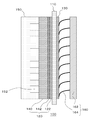
- FIG. 2 is an exploded perspective view illustrating a schematic configuration of an electrode unit included in the electrochemical reduction device 10 according to the embodiment.
- FIG. 3 is a side view illustrating a schematic configuration of an electrode unit included in the electrochemical reduction device 10 according to the embodiment.
- the electrochemical reduction device 10 includes an electrode unit 100, a power control unit 20, an organic substance storage tank 30, a water storage tank 40, a steam / water separation unit 50, and a control unit 60.
- the power control unit 20 is, for example, a DC / DC converter that converts the output voltage of the power source into a predetermined voltage.
- the positive electrode output terminal of the power control unit 20 is connected to the oxygen generation electrode (positive electrode) 130 of the electrode unit 100.
- the negative output terminal of the power control unit 20 is connected to the reduction electrode (negative electrode) 120 of the electrode unit 100. Thereby, a predetermined voltage is applied between the oxygen generation electrode 130 and the reduction electrode 120 of the electrode unit 100.
- the power control unit 20 may be provided with a reference electrode for the purpose of positive and negative potential detection.
- the reference electrode input terminal is connected to a reference electrode 112 provided on the electrolyte membrane 110 described later.
- the outputs of the positive electrode output terminal and the negative electrode output terminal of the power control unit 20 are controlled so that the potentials of the oxygen generation electrode 130 and the reduction electrode 120 when the potential of the reference electrode 112 is a reference are set to desired potentials. Controlled by.
- a power source Normal system
- strain power may be used and the electric power derived from natural energy, such as sunlight and a wind force, can also be used preferably.
- the aromatic compound used in this embodiment is an aromatic hydrocarbon compound containing at least one aromatic ring or a nitrogen-containing heterocyclic aromatic compound.
- the aromatic compound include benzene, naphthalene, anthracene, diphenylethane, pyridine, pyrimidine, pyrazine, quinoline, isoquinoline, N-alkylpyrrole, N-alkylindole, and N-alkyldibenzopyrrole.
- 1 to 4 hydrogen atoms of the aromatic rings of the above aromatic hydrocarbon and nitrogen-containing heterocyclic aromatic compound may be substituted with an alkyl group.
- alkyl in the aromatic compound is a straight-chain alkyl group or branched alkyl group having 1 to 6 carbon atoms.
- examples of the alkylbenzene include toluene and ethylbenzene
- examples of the dialkylbenzene include xylene and diethylbenzene
- examples of the trialkylbenzene include mesitylene.
- examples of the alkyl naphthalene include methyl naphthalene.
- the aromatic ring of the above-mentioned aromatic hydrocarbon and nitrogen-containing heterocyclic aromatic compound may have 1 to 3 substituents.
- the aromatic hydrocarbon compound and the nitrogen-containing heterocyclic aromatic compound may be collectively referred to as “aromatic compound”.
- the aromatic compound is preferably liquid at normal temperature. Moreover, what is necessary is just to be a liquid as a mixture, when using what mixed two or more among the above-mentioned aromatic compounds. According to this, since the aromatic compound can be supplied to the electrode unit 100 in a liquid state without performing processing such as heating and pressurization, the configuration of the electrochemical reduction device 10 can be simplified. it can.
- the concentration of the aromatic carbide compound in the liquid state is 0.1% or more, preferably 0.3% or more, more preferably 0.5% or more.
- the aromatic compound stored in the organic substance storage tank 30 is supplied to the reduction electrode 120 of the electrode unit 100 by the first liquid supply device 32.
- the first liquid supply device 32 for example, various pumps such as a gear pump or a cylinder pump, a natural flow-down device, or the like can be used.
- the aromatic compound an N-substituted product of the above-described aromatic compound may be used.
- a circulation path is provided between the organic substance storage tank 30 and the reduction electrode 120 of the electrode unit 100. Then, the aromatic compound nuclear-hydrogenated by the electrode unit 100 and the unreacted aromatic compound are stored in the organic matter storage tank 30 through a circulation path. Gas is not generated in the main reaction that proceeds at the reduction electrode 120 of the electrode unit 100, but when a gas such as hydrogen is by-produced, a gas-liquid separation unit may be provided in the middle of the circulation path.
- water for example, ion exchange water, pure water, or an aqueous solution in which an acid such as sulfuric acid is added (hereinafter simply referred to as “water”) is stored.
- the water stored in the water storage tank 40 is supplied to the oxygen generating electrode 130 of the electrode unit 100 by the second liquid supply device 42.
- various pumps such as a gear pump or a cylinder pump, a natural flow-down device, or the like can be used for the second liquid supply device 42.
- a circulation path is provided between the water storage tank 40 and the oxygen generating electrode 130 of the electrode unit 100. Then, unreacted water in the electrode unit 100 is stored in the water storage tank 40 through a circulation path.
- a steam / water separator 50 is provided in the middle of a path for returning unreacted water from the electrode unit 100 to the water storage tank 40.
- a gas such as oxygen generated by electrolysis of water in the electrode unit 100 is separated from the water by the steam / water separator 50 and discharged out of the system.
- the electrode unit 100 includes an electrolyte membrane 110, a reduction electrode catalyst layer 122, a diffusion layer 140, and a reduction electrode 120 having a dense layer 142, an oxygen generation electrode 130, a separator 150, and a current collector. It has a body 160.
- the electrode unit 100 is illustrated in a simplified manner, and the separator 150 and the current collector 160 are omitted.
- the electrolyte membrane 110 is formed of a material having proton conductivity (ionomer), and selectively conducts protons while mixing and diffusing substances between the reduction electrode 120 and the oxygen generating electrode 130. To suppress that.
- the thickness of the electrolyte membrane 110 is preferably 5 to 300 ⁇ m, more preferably 10 to 150 ⁇ m, and most preferably 20 to 100 ⁇ m. When the thickness of the electrolyte membrane 110 is less than 5 ⁇ m, the barrier property of the electrolyte membrane 110 is lowered, and cross leakage is likely to occur. On the other hand, if the thickness of the electrolyte membrane 110 is greater than 300 ⁇ m, the ion migration resistance becomes excessive, which is not preferable.
- Sheet resistance of the electrolyte membrane 110 i.e., ion transfer resistance per geometric area, preferably 2000m ⁇ ⁇ cm 2 or less, more preferably 1000M ⁇ cm 2 or less, and most preferably 500m ⁇ ⁇ cm 2 or less.
- proton conductivity may be insufficient.
- the material having proton conductivity include perfluorosulfonic acid polymers such as Nafion (registered trademark) and Flemion (registered trademark).
- the ion exchange capacity (IEC) of the cation exchange ionomer is preferably 0.7 to 2 meq / g, more preferably 1 to 1.2 meq / g.
- IEC ion exchange capacity
- the ion exchange capacity of the cation exchange ionomer is less than 0.7 meq / g, the ion conductivity may be insufficient.
- the solubility of the ionomer in water increases, and thus the strength of the electrolyte membrane 110 may be insufficient.
- a reference electrode 112 may be provided on the electrolyte membrane 110 so as to be in contact with the electrolyte membrane 110 in a region separated from the reduction electrode 120 and the oxygen generation electrode 130. That is, the reference electrode 112 is electrically isolated from the reduction electrode 120 and the oxygen generation electrode 130.
- the reference electrode 112 is held at the reference electrode potential V Ref .
- the reference electrode 112 is preferably installed on the surface of the electrolyte membrane 110 on the reduction electrode 120 side.
- the current I flowing between the reduction electrode 120 and the oxygen generation electrode 130 is detected by the current detection unit 113 shown in FIG.
- the value of the current I detected by the current detection unit 113 may be input to the control unit 60 and used for controlling the power control unit 20 by the control unit 60.
- the potential difference ⁇ V CA between the reference electrode 112 and the reduction electrode 120 is detected by the voltage detection unit 114 shown in FIG.
- the value of the potential difference ⁇ V CA detected by the voltage detection unit 114 may be input to the control unit 60 and used for controlling the power control unit 20 by the control unit 60.
- the reduction electrode 120 is provided in contact with one main surface of the electrolyte membrane 110.
- the reduction electrode 120 is a laminate in which a reduction electrode catalyst layer 122, a dense layer 142, and a diffusion layer 140 are laminated in this order from the electrolyte membrane 110 side.
- the reducing electrode catalyst layer 122 is provided in contact with one main surface of the electrolyte membrane 110.
- the reduction electrode catalyst layer 122 includes a reduction catalyst for nuclear hydrogenation of the aromatic compound.
- the reduction catalyst used for the reduction electrode catalyst layer 122 contains at least one of Pt and Pd.
- the reduction catalyst includes a first catalytic metal (noble metal) made of at least one of Pt and Pd, and Cr, Mn, Fe, Co, Ni, Cu, Zn, Mo, Ru, Sn, W, Re, Pb, You may be comprised with the metal composition containing the 1 type, or 2 or more types of 2nd catalyst metal selected from Bi.
- the form of the metal composition is an alloy of the first catalyst metal and the second catalyst metal, or an intermetallic compound composed of the first catalyst metal and the second catalyst metal.
- the ratio of the first catalyst metal to the total mass of the first catalyst metal and the second catalyst metal is preferably 10 to 95 wt%, more preferably 20 to 90 wt%, and most preferably 25 to 80 wt%.
- the ratio of the first catalyst metal is lower than 10 wt%, durability may be lowered in terms of dissolution resistance.
- the ratio of the first catalyst metal is higher than 95 wt%, the properties of the reduction catalyst approach the properties of the noble metal alone, and thus the electrode activity may be insufficient.
- the first catalyst metal and the second catalyst metal may be collectively referred to as “catalyst metal”.
- the catalyst metal described above may be supported on an electron conductive material (support).
- the electron conductivity of the electron conductive material is preferably 1.0 ⁇ 10 ⁇ 2 S / cm or more, more preferably 3.0 ⁇ 10 ⁇ 2 S / cm or more, and 1.0 ⁇ 10 ⁇ 1 S / cm or more. Is most preferred. If the electron conductivity of the electron conductive material is less than 1.0 ⁇ 10 ⁇ 2 S / cm, sufficient electron conductivity may not be imparted.
- Examples of the electron conductive material include electron conductive materials containing any one of porous carbon, porous metal, and porous metal oxide as a main component.
- porous carbon examples include carbon black such as ketjen black (registered trademark), acetylene black, and Vulcan (registered trademark).
- the BET specific surface area of the porous carbon measured by the nitrogen adsorption method is preferably 100 m 2 / g or more, more preferably 150 m 2 / g or more, and most preferably 200 m 2 / g or more.
- the BET specific surface area of the porous carbon is smaller than 100 m 2 / g, it becomes difficult to uniformly support the catalyst metal. For this reason, the utilization factor of the catalyst metal surface may be reduced, and the catalyst performance may be reduced.
- the porous metal include Pt black, Pd black, and Pt metal deposited in a fractal shape.
- porous metal oxide examples include oxides of Ti, Zr, Nb, Mo, Hf, Ta, and W.
- a metal nitride such as Ti, Zr, Nb, Mo, Hf, Ta, W, carbide, oxynitride, carbonitride, partial Oxidized carbonitrides (hereinafter collectively referred to as porous metal carbonitrides and the like) can be mentioned.
- the BET specific surface area of the porous metal, porous metal oxide, porous metal carbonitride and the like measured by the nitrogen adsorption method is preferably 1 m 2 / g or more, more preferably 3 m 2 / g or more, and 10 m 2 / g. The above is most preferable. If the BET specific surface area of the porous metal, the porous metal oxide, the porous metal carbonitride, or the like is smaller than 1 m 2 / g, it becomes difficult to uniformly support the catalyst metal. For this reason, the utilization factor of the catalyst metal surface may be reduced, and the catalyst performance may be reduced.
- a material having electron conductivity such as the above-described electron conductive oxide or carbon black may be added separately from the electron conductive compound supporting the catalyst metal. Thereby, the electron conduction path between the reduction catalyst particles can be increased, and the resistance per geometric area of the reduction catalyst layer can be lowered in some cases.
- the reducing electrode catalyst layer 122 may contain a fluorine-based resin such as polytetrafluoroethylene (PTFE) as an additive.
- PTFE polytetrafluoroethylene
- the reducing electrode catalyst layer 122 may include an ionomer having proton conductivity.
- the reducing electrode catalyst layer 122 preferably contains an ion conductive material (ionomer) having the same or similar structure as the electrolyte membrane 110 described above at a predetermined mass ratio. According to this, the ion conductivity in the reducing electrode catalyst layer 122 can be improved.
- the reducing electrode catalyst layer 122 contains an ionomer having proton conductivity, which greatly contributes to improvement of ion conductivity.
- ionomers having proton conductivity include perfluorosulfonic acid polymers such as Nafion (registered trademark) and Flemion (registered trademark).
- the ion exchange capacity (IEC) of the cation exchange ionomer is preferably 0.7 to 3 meq / g, more preferably 1 to 2.5 meq / g, and most preferably 1.2 to 2 meq / g.
- the cation exchange ionomer (I) / carbon support (C) mass ratio I / C is preferably 0.1 to 2, 2 to 1.5 is more preferable, and 0.3 to 1.1 is most preferable.
- the mass ratio I / C is lower than 0.1, it may be difficult to obtain sufficient ionic conductivity.
- the mass ratio I / C is greater than 2, the coating thickness of the ionomer on the catalytic metal increases, which prevents the aromatic compound as a reactant from contacting the catalytic active point or decreases the electronic conductivity. Doing so may reduce the electrode activity.
- the ionomer contained in the reduction electrode catalyst layer 122 partially covers the reduction catalyst. According to this, three elements (aromatic compound, proton, electron) necessary for the electrochemical reaction in the reducing electrode catalyst layer 122 can be efficiently supplied to the reaction field.
- the dense layer 142 is provided in contact with the main surface on the opposite side of the two main surfaces of the reducing electrode catalyst layer 122 with which the electrolyte membrane 110 is in contact.
- the dense layer 142 has a function of allowing liquid aromatic compounds and aromatic compound hydrides having relatively low surface tension to pass therethrough and suppressing passage of liquid water having relatively high surface tension. .
- the diffusion layer 140 is provided in contact with the main surface on the opposite side to the side on which the reducing electrode catalyst layer 122 is in contact with the two main surfaces of the dense layer 142.
- the diffusion layer 140 is made of a porous material or fiber that penetrates a liquid aromatic compound and a hydride of an aromatic compound supplied from a separator 150, which will be described later, and has good electron conductivity.
- the material which comprises the diffused layer 140 has high affinity with the aromatic compound mentioned above.
- carbon paper, carbon woven fabric, or non-woven fabric can be used as the material constituting the diffusion layer 140.
- the thickness of the diffusion layer 140 is preferably 50 to 1000 ⁇ m, and more preferably 100 to 500 ⁇ m.
- the electronic conductivity of the material constituting the diffusion layer 140 is preferably 10 ⁇ 2 S / cm or more.
- the diffusion layer 140 a material in which corrosion-resistant alloy fine particles such as Cr—Mo are condensed can be used for the diffusion layer 140.
- the metal surface is preferably subjected to processing such as water repellent treatment and lipophilic treatment.
- the dense layer 142 is formed by applying and drying a paste-like kneaded material obtained by kneading the electron conductive powder and the water repellent to the diffusion layer 140 so as to fill the gap between the diffusion layers 140.
- the electron conductive powder conductive carbon such as Vulcan (registered trademark) can be used.
- As the water repellent a fluorine resin such as tetrafluoroethylene resin (PTFE) can be used.
- the ratio between the electron conductive powder and the water repellent is appropriately determined within a range where desired electron conductivity and water repellency can be obtained.
- Vulcan registered trademark
- PTFE is used as the water repellent.
- the mass ratio is, for example, 4: 1 to 1: 1 (Vulcan: PTFE).
- the dense layer 142 has an average flow pore diameter dm of preferably 100 nm to 20 ⁇ m, and more preferably 500 nm to 5 ⁇ m. Further, the thickness of the dense layer 142 is preferably 1 to 50 ⁇ m, and more preferably 2 to 20 ⁇ m. In the case where the dense layer 142 is formed so as to drop inward from the surface of the diffusion layer 140, the average film thickness of the dense layer 142 itself including the portion hidden in the diffusion layer 140 is the thickness. Define.
- protons such as an ionomer (electrolyte) in the reducing electrode catalyst layer 122 and a cathode side of the electrolyte membrane 110 are provided.
- Water can be easily retained at the conduction site.
- the proton reduction reaction on the reduction electrode 120 side can be facilitated in the presence of a large amount of an organic substance such as an aromatic compound.
- the separator 150 is laminated on the main surface of the diffusion layer 140 on the side opposite to the electrolyte membrane 110.
- the separator 150 is formed of a corrosion-resistant alloy such as carbon resin, Cr—Ni—Fe, Cr—Ni—Mo—Fe, Cr—Mo—Nb—Ni, Cr—Mo—Fe—W—Ni. .
- One or a plurality of groove-shaped flow paths 152 are provided on the surface of the separator 150 on the diffusion layer 140 side.
- the liquid aromatic compound supplied from the organic substance storage tank 30 circulates in the flow path 152, and the liquid aromatic compound soaks into the diffusion layer 140 from the flow path 152.
- the form of the flow path 152 is not specifically limited, For example, a linear flow path and a serpentine flow path can be adopted.
- the separator 150 may be a structure obtained by sintering spherical or pellet-shaped metal fine powder.
- the oxygen generating electrode 130 is provided in contact with the other main surface of the electrolyte membrane 110.
- the oxygen generating electrode 130 includes one or more metals or metal oxides selected from Ru, Rh, Pd, Ir, and Pt as a catalyst.
- These catalysts include metal fibers such as metals such as Ti, Cr, Mn, Fe, Co, Ni, Cu, Zn, Nb, Mo, Ta, and W or alloys based on them (fiber diameter: for example, 10 to 30 ⁇ m), mesh (diameter: 500 to 1000 ⁇ m, for example), metal porous sintered body, foamed molded body (foam), expanded metal, etc. may be dispersedly supported or coated. .
- the thickness of the catalyst layer is preferably 0.1 to 10 ⁇ m, more preferably 0.2 to 5 ⁇ m.
- the surface of the metal substrate may be covered with an electron conductive protective layer made of one or more metals selected from Nb, Mo, Ta, and W or a metal oxide.
- the thickness of the protective layer is preferably 0.05 to 2 ⁇ m, more preferably 0.1 to 1 ⁇ m.
- the metal substrate functions as a current collecting member in addition to the role as a substrate for holding the catalyst.
- FIG. 4 is a schematic diagram showing an example of a cross-sectional structure of the oxygen generating electrode 130 in an enlarged manner.
- the catalyst 136 is held on the surface of the protective layer 134 that covers the metal substrate 132.
- the metal substrate 132 is an expanded metal formed of a metal material such as Ti.
- the protective layer 134 is formed of one or more metals or metal oxides selected from Nb, Mo, Ta, and W.
- the catalyst 136 is formed of one or more metals or metal oxides selected from Ru, Rh, Pd, Ir, and Pt.
- the electrode unit 100 is provided with a current collector 160 that is electrically connected to the oxygen generating electrode 130 described above.
- the current collector 160 includes a base material portion 162 and a connection portion 164 that are formed of a metal having good electronic conductivity such as copper or aluminum.
- the base material portion 162 is a planar metal member that is set apart from the oxygen generating electrode 130 by a predetermined distance. A space between the base material portion 162 and the oxygen generation electrode 130 is used for circulation of water supplied to the oxygen generation electrode 130.
- connection portion 164 of the present embodiment is a metal member obtained by bending the short side of a strip-shaped member.
- the plurality of connecting portions 164 are provided side by side with a predetermined interval in a state where one long side is fixed to the base material portion 162.
- the plurality of connection portions 164 are electrically connected to the oxygen generation electrode 130 at the other long side.
- Each connection part 164 and the oxygen generation electrode 130 may be fixed by welding or the like. Since the connecting portion 164 has a curved short side, it can serve as a spring. For this reason, the contact of the connection part 164 and the oxygen generation electrode 130 can be made more reliable by pressing the base material part 162 toward the oxygen generation electrode 130.
- the connection portion 164 has a strip shape, but the shape of the connection portion 164 is not limited to this.
- the connection part 164 may be configured by a spring-like wire or the like.
- liquid water is supplied to the oxygen generating electrode 130, but humidified gas (for example, air) may be used instead of liquid water.
- humidified gas for example, air
- the dew point temperature of the humidified gas is preferably room temperature to 100 ° C, more preferably 50 to 100 ° C.
- the aromatic compound is uniformly and rapidly supplied to the reaction site of the reducing electrode catalyst layer 122, and the hydride of the aromatic compound. Is quickly removed from the reaction site. For this reason, the hydrogenation reaction of an aromatic compound can be accelerated
- the dense layer 142 is provided between the diffusion layer 140 and the reducing electrode catalyst layer 122, a certain amount of moisture can be retained in the reducing electrode catalyst layer 122, so that the electrolyte membrane 110 and the reducing electrode catalyst layer 122 are retained. Can be suppressed, and the hydrogenation reaction of the aromatic compound can be further promoted.
- Table 1 shows the configurations of the electrode units of Examples 1 to 5 and Comparative Example 1. Each electrode unit was evaluated using toluene as an aromatic compound. The differences between the electrode units of Examples 1 to 5 and Comparative Example 1 are as follows. That is, the electrode units of Examples 1 to 5 have a dense layer, whereas the electrode unit of Comparative Example 1 does not have a dense layer. In addition, the average flow pore diameters dm of the dense layers of Examples 1 to 5 were 3.2 ⁇ m, 1.1 ⁇ m, 0.76 ⁇ m, 1 ⁇ m, and 23 ⁇ m, respectively. As the material for the dense layers of Examples 1 to 5, Vulcan (registered trademark) was used as the electron conductive powder, and PTFE was used as the water repellent.
- Vulcan registered trademark
- Example 1 the mass ratio of Vulcan to PTFE was 1: 1, and for Example 3, the ratio was 4: 1.
- the thicknesses of the dense layers in Examples 1 to 5 were 8.6 ⁇ m, 8.5 ⁇ m, 8.4 ⁇ m, 0.76 ⁇ m, and 9.6 ⁇ m, respectively.
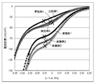
- FIG. 5 is an IV curve obtained for each electrode unit of Examples 1 to 5 and Comparative Example 1. As shown in FIG. 5, it was confirmed that when the potential difference between the reduction electrode and the reference electrode was the same, the absolute value of the current density increased in Examples 1 to 5 compared to Comparative Example 1. In particular, in Examples 1 to 3, it was confirmed that the absolute value of the current density significantly increased. Further, the concentration of toluene supplied to the reduction electrode was detected under the condition that the absolute value of the current density was 50 mA / cm 2 . Further, the amount of the converted substance was determined from the change in toluene concentration by gas chromatography.
- the electric quantity was calculated
- the results obtained for Faraday efficiency are shown in Table 2.
- the hydrogenation of toluene is dominant, in other words, the Faraday efficiency is almost 100%, the region where toluene hydrogenation proceeds selectively, and the Faraday efficiency is less than 100%.
- the absolute value of the current density was measured at the boundary point (point indicated by a mark x in FIG. 5) with the region where the advancing in a competitive manner. The results obtained for this boundary point are shown in Table 2.
- a diffusion layer that uniformly diffuses water into the oxygen generation electrode 130 and oxygen generation on the oxygen generation electrode 130 side as in the reduction electrode 120 side
- a separator having a flow path for circulating water supplied to the electrode 130 may be installed.
- Electrochemical reduction device 20 Power control unit, 30 Organic storage tank, 40 Water storage tank, 50 Air / water separation unit, 60 Control unit, 100 Electrode unit, 112, Reference electrode, 113 Current detection unit, 114 Voltage detection unit, 110 electrolyte membrane, 120 reduction electrode, 122 reduction electrode catalyst layer, 130 oxygen generation electrode, 140 diffusion layer, 142 dense layer, 150 separator, 160 current collector
- the present invention can be used for an electrochemical reduction apparatus.
Abstract
Description
図1は、実施の形態に係る電気化学還元装置10の概略構成を示す模式図である。図2は、実施の形態に係る電気化学還元装置10が有する電極ユニットの概略構成を示す分解斜視図である。図3は、実施の形態に係る電気化学還元装置10が有する電極ユニットの概略構成を示す側面図である。 (Embodiment)
FIG. 1 is a schematic diagram illustrating a schematic configuration of an
<酸素発生用電極での電極反応>
3H2O→1.5O2+6H++6e-:E0=1.23V
<還元電極での電極反応>
トルエン+6H++6e-→メチルシクロヘキサン:E0=0.153V(vs RHE)
すなわち、酸素発生用電極での電極反応と、還元電極での電極反応とが並行して進行し、酸素発生用電極130での電極反応によって、水の電気分解により生じたプロトンが電解質膜110を介して還元電極120に供給される。還元電極120に供給されたプロトンは、還元電極120での電極反応において、芳香族化合物の核水素化に利用される。 The reaction in the
<Electrode reaction at oxygen generating electrode>
3H 2 O → 1.5 O 2 + 6H + + 6e − : E 0 = 1.23V
<Electrode reaction at the reduction electrode>
Toluene + 6H + + 6e − → Methylcyclohexane: E 0 = 0.153 V (vs RHE)
That is, the electrode reaction at the oxygen generation electrode and the electrode reaction at the reduction electrode proceed in parallel, and protons generated by the electrolysis of water by the electrode reaction at the


Claims (8)
- プロトン伝導性を有する電解質膜と、
前記電解質膜の一方の主表面に接して設けられ、電子伝導性材料と前記電子伝導性材料に担持されたPt、Pdのいずれかまたは両方を含む金属とを有する還元極触媒層、前記電解質膜と反対側の前記還元極触媒層の主表面側に設けられ、液体の芳香族化合物および前記芳香族化合物の水素化体を通過させる拡散層、および前記拡散層と前記還元極触媒層との間に設けられる緻密層を有する還元電極と、
前記電解質膜の他方の主表面に接して設けられた酸素発生用電極と、
前記還元電極へ液体の状態で前記芳香族化合物を供給する原料供給手段と、
前記酸素発生用電極に水または加湿したガスを供給する水分供給手段と、
前記還元電極が卑な電位、前記酸素発生用電極が貴な電位となるよう外部から電場をかける電力制御部と、
を備えることを特徴とする電気化学還元装置。 An electrolyte membrane having proton conductivity;
A reducing electrode catalyst layer provided in contact with one main surface of the electrolyte membrane and having an electron conductive material and a metal containing either or both of Pt and Pd supported on the electron conductive material, the electrolyte membrane A diffusion layer that is provided on the main surface side of the reduction electrode catalyst layer on the opposite side of the liquid and passes a liquid aromatic compound and a hydride of the aromatic compound, and between the diffusion layer and the reduction electrode catalyst layer A reduction electrode having a dense layer provided on
An oxygen generating electrode provided in contact with the other main surface of the electrolyte membrane;
Raw material supply means for supplying the aromatic compound in a liquid state to the reduction electrode;
Moisture supply means for supplying water or humidified gas to the oxygen generating electrode;
A power control unit that applies an electric field from the outside so that the reduction electrode has a base potential and the oxygen generation electrode has a noble potential;
An electrochemical reduction device comprising: - 前記緻密層の平均流量細孔径が20μm以下である請求項1に記載の電気化学還元装置。 The electrochemical reduction device according to claim 1, wherein the dense layer has an average flow pore size of 20 μm or less.
- 前記緻密層の厚さが1μm以上50μm以下である請求項1または2に記載の電気化学還元装置。 The electrochemical reduction device according to claim 1 or 2, wherein the dense layer has a thickness of 1 µm to 50 µm.
- 前記緻密層が電子伝導性粉末と撥水剤の混合物を含む請求項1乃至3のいずれか1項に記載の電気化学還元装置。 The electrochemical reduction apparatus according to any one of claims 1 to 3, wherein the dense layer includes a mixture of an electron conductive powder and a water repellent.
- 前記混合物における前記電子伝導性粉末と前記撥水剤の質量比は、前記撥水剤に対して前記電子伝導性粉末が4倍以上である請求項4に記載の電気化学還元装置。 The electrochemical reduction device according to claim 4, wherein a mass ratio of the electron conductive powder and the water repellent in the mixture is 4 times or more that of the electron conductive powder with respect to the water repellent.
- 前記拡散層が繊維状または多粒子を凝結させた形状である請求項1乃至5のいずれか1項に記載の電気化学還元装置。 The electrochemical reduction device according to any one of claims 1 to 5, wherein the diffusion layer has a shape in which fibers or multi-particles are condensed.
- 前記拡散層がカーボン繊維を含む請求項1乃至6のいずれか1項に記載の電気化学還元装置。 The electrochemical reduction device according to any one of claims 1 to 6, wherein the diffusion layer includes carbon fibers.
- 前記拡散層が1.0×10⁻²S/cm以上の電子伝導性を有する材料を含む請求項1乃至7のいずれか1項に記載の電気化学還元装置。 The electrochemical reduction device according to claim 1, wherein the diffusion layer includes a material having an electron conductivity of 1.0 × 10 −2 S / cm or more.
Priority Applications (3)
| Application Number | Priority Date | Filing Date | Title |
|---|---|---|---|
| EP14840785.1A EP3040449B1 (en) | 2013-08-30 | 2014-08-18 | Electrochemical reduction device |
| JP2015533967A JP6454642B2 (en) | 2013-08-30 | 2014-08-18 | Electrochemical reduction device |
| US15/054,610 US20160177459A1 (en) | 2013-08-30 | 2016-02-26 | Electrochemical reduction device |
Applications Claiming Priority (2)
| Application Number | Priority Date | Filing Date | Title |
|---|---|---|---|
| JP2013-179555 | 2013-08-30 | ||
| JP2013179555 | 2013-08-30 |
Related Child Applications (1)
| Application Number | Title | Priority Date | Filing Date |
|---|---|---|---|
| US15/054,610 Continuation US20160177459A1 (en) | 2013-08-30 | 2016-02-26 | Electrochemical reduction device |
Publications (1)
| Publication Number | Publication Date |
|---|---|
| WO2015029366A1 true WO2015029366A1 (en) | 2015-03-05 |
Family
ID=52585959
Family Applications (1)
| Application Number | Title | Priority Date | Filing Date |
|---|---|---|---|
| PCT/JP2014/004211 WO2015029366A1 (en) | 2013-08-30 | 2014-08-18 | Electrochemical reduction device |
Country Status (5)
| Country | Link |
|---|---|
| US (1) | US20160177459A1 (en) |
| EP (1) | EP3040449B1 (en) |
| JP (1) | JP6454642B2 (en) |
| AR (1) | AR097467A1 (en) |
| WO (1) | WO2015029366A1 (en) |
Cited By (3)
| Publication number | Priority date | Publication date | Assignee | Title |
|---|---|---|---|---|
| JP2017160475A (en) * | 2016-03-08 | 2017-09-14 | Jxtgエネルギー株式会社 | Catalyst layer, membrane electrode assembly, electrolytic cell, and method for producing catalyst layer |
| CN108195010A (en) * | 2017-12-28 | 2018-06-22 | 青岛海尔空调电子有限公司 | The control method of electrode humidifier |
| WO2018216356A1 (en) * | 2017-05-23 | 2018-11-29 | 国立大学法人横浜国立大学 | Organic hydride production device |
Families Citing this family (3)
| Publication number | Priority date | Publication date | Assignee | Title |
|---|---|---|---|---|
| JP6758628B2 (en) | 2016-11-15 | 2020-09-23 | 国立大学法人横浜国立大学 | Organic hydride manufacturing equipment and organic hydride manufacturing method |
| JP6823000B2 (en) * | 2018-03-20 | 2021-01-27 | 株式会社東芝 | Carbon dioxide electrolyzer |
| CN108483583B (en) * | 2018-04-03 | 2020-10-27 | 西安交通大学 | IrO (IrO)2·Ta2O5Preparation method of coated titanium electrode |
Citations (7)
| Publication number | Priority date | Publication date | Assignee | Title |
|---|---|---|---|---|
| JP2003045449A (en) | 2001-08-01 | 2003-02-14 | Masaru Ichikawa | Chemical power generation/device for manufacturing organic hydride and chemical power generation/ manufacturing method for organic hydride |
| JP2005126288A (en) | 2003-10-24 | 2005-05-19 | Toyota Motor Corp | Hydrogen storage and release apparatus |
| JP2005239479A (en) | 2004-02-26 | 2005-09-08 | Toyota Motor Corp | Hydrogen gas separating equipment and hydrogen gas generation equipment |
| WO2006043394A1 (en) * | 2004-10-19 | 2006-04-27 | Matsushita Electric Industrial Co., Ltd. | Membrane electrode assembly, method for producing same and polymer electrolyte fuel cell |
| WO2011122155A1 (en) * | 2010-03-31 | 2011-10-06 | 株式会社日立製作所 | Device for manufacturing organic hydride |
| WO2013111585A1 (en) * | 2012-01-24 | 2013-08-01 | Jx日鉱日石エネルギー株式会社 | Electrochemical reduction device and method for producing hydride of nitrogen-containing-heterocyclic aromatic compound or aromatic hydrocarbon compound |
| WO2013125238A1 (en) * | 2012-02-23 | 2013-08-29 | Jx日鉱日石エネルギー株式会社 | Electrochemical reduction device and method for producing hydrogenated product of aromatic hydrocarbon compound or nitrogen-containing heterocyclic aromatic compound |
Family Cites Families (2)
| Publication number | Priority date | Publication date | Assignee | Title |
|---|---|---|---|---|
| JP2012072477A (en) * | 2010-09-30 | 2012-04-12 | Hitachi Ltd | Device for manufacturing organic hydride |
| JP2013084360A (en) * | 2011-10-06 | 2013-05-09 | Hitachi Ltd | Membrane-electrode assembly, and device for organic hydride production |
-
2014
- 2014-08-18 WO PCT/JP2014/004211 patent/WO2015029366A1/en active Application Filing
- 2014-08-18 EP EP14840785.1A patent/EP3040449B1/en active Active
- 2014-08-18 JP JP2015533967A patent/JP6454642B2/en active Active
- 2014-08-27 AR ARP140103209A patent/AR097467A1/en unknown
-
2016
- 2016-02-26 US US15/054,610 patent/US20160177459A1/en not_active Abandoned
Patent Citations (7)
| Publication number | Priority date | Publication date | Assignee | Title |
|---|---|---|---|---|
| JP2003045449A (en) | 2001-08-01 | 2003-02-14 | Masaru Ichikawa | Chemical power generation/device for manufacturing organic hydride and chemical power generation/ manufacturing method for organic hydride |
| JP2005126288A (en) | 2003-10-24 | 2005-05-19 | Toyota Motor Corp | Hydrogen storage and release apparatus |
| JP2005239479A (en) | 2004-02-26 | 2005-09-08 | Toyota Motor Corp | Hydrogen gas separating equipment and hydrogen gas generation equipment |
| WO2006043394A1 (en) * | 2004-10-19 | 2006-04-27 | Matsushita Electric Industrial Co., Ltd. | Membrane electrode assembly, method for producing same and polymer electrolyte fuel cell |
| WO2011122155A1 (en) * | 2010-03-31 | 2011-10-06 | 株式会社日立製作所 | Device for manufacturing organic hydride |
| WO2013111585A1 (en) * | 2012-01-24 | 2013-08-01 | Jx日鉱日石エネルギー株式会社 | Electrochemical reduction device and method for producing hydride of nitrogen-containing-heterocyclic aromatic compound or aromatic hydrocarbon compound |
| WO2013125238A1 (en) * | 2012-02-23 | 2013-08-29 | Jx日鉱日石エネルギー株式会社 | Electrochemical reduction device and method for producing hydrogenated product of aromatic hydrocarbon compound or nitrogen-containing heterocyclic aromatic compound |
Non-Patent Citations (1)
| Title |
|---|
| See also references of EP3040449A4 |
Cited By (4)
| Publication number | Priority date | Publication date | Assignee | Title |
|---|---|---|---|---|
| JP2017160475A (en) * | 2016-03-08 | 2017-09-14 | Jxtgエネルギー株式会社 | Catalyst layer, membrane electrode assembly, electrolytic cell, and method for producing catalyst layer |
| WO2018216356A1 (en) * | 2017-05-23 | 2018-11-29 | 国立大学法人横浜国立大学 | Organic hydride production device |
| CN108195010A (en) * | 2017-12-28 | 2018-06-22 | 青岛海尔空调电子有限公司 | The control method of electrode humidifier |
| CN108195010B (en) * | 2017-12-28 | 2020-07-07 | 青岛海尔空调电子有限公司 | Control method of electrode humidifier |
Also Published As
| Publication number | Publication date |
|---|---|
| EP3040449B1 (en) | 2018-03-21 |
| JP6454642B2 (en) | 2019-01-16 |
| JPWO2015029366A1 (en) | 2017-03-02 |
| US20160177459A1 (en) | 2016-06-23 |
| EP3040449A1 (en) | 2016-07-06 |
| EP3040449A4 (en) | 2017-03-01 |
| AR097467A1 (en) | 2016-03-16 |
Similar Documents
| Publication | Publication Date | Title |
|---|---|---|
| JP6096129B2 (en) | Electrochemical reduction apparatus and method for producing hydrogenated aromatic hydrocarbon compound | |
| JP6454642B2 (en) | Electrochemical reduction device | |
| JP6786426B2 (en) | Electrochemical reduction device and method for producing a hydrogenated product of an aromatic hydrocarbon compound | |
| US9752239B2 (en) | Electrochemical reduction device and method for manufacturing hydride of aromatic hydrocarbon compound or nitrogen-containing heterocyclic aromatic compound | |
| JP6086873B2 (en) | Electrochemical reduction apparatus and method for producing hydrogenated aromatic hydrocarbon compound | |
| JP7072161B2 (en) | Sith-Alkene manufacturing equipment and manufacturing method | |
| JP5072652B2 (en) | Water electrolysis equipment | |
| WO2018037774A1 (en) | Cathode, electrolysis cell for producing organic hydride, and organic hydride production method | |
| WO2018216356A1 (en) | Organic hydride production device | |
| JP6113715B2 (en) | Electrochemical reduction apparatus and method for producing hydrogenated product of aromatic hydrocarbon compound or nitrogen-containing heterocyclic aromatic compound | |
| JP6373851B2 (en) | Electrochemical reduction device | |
| JP6998797B2 (en) | Organic hydride manufacturing equipment, organic hydride manufacturing method and energy transportation method | |
| US20150114842A1 (en) | Electrochemical reduction device and method of manufacturing hydride of aromatic hydrocarbon compound or nitrogen-containing heterocyclic aromatic compound | |
| JP6736048B2 (en) | Catalyst layer, membrane electrode assembly, electrolytic cell, and method for producing catalyst layer | |
| JP2023128449A (en) | Cathode, membrane electrode assembly and organic hydride production device |
Legal Events
| Date | Code | Title | Description |
|---|---|---|---|
| 121 | Ep: the epo has been informed by wipo that ep was designated in this application |
Ref document number: 14840785 Country of ref document: EP Kind code of ref document: A1 |
|
| ENP | Entry into the national phase |
Ref document number: 2015533967 Country of ref document: JP Kind code of ref document: A |
|
| NENP | Non-entry into the national phase |
Ref country code: DE |
|
| REEP | Request for entry into the european phase |
Ref document number: 2014840785 Country of ref document: EP |
|
| WWE | Wipo information: entry into national phase |
Ref document number: 2014840785 Country of ref document: EP |