WO2015022893A1 - 摩擦撹拌接合方法 - Google Patents
摩擦撹拌接合方法 Download PDFInfo
- Publication number
- WO2015022893A1 WO2015022893A1 PCT/JP2014/070732 JP2014070732W WO2015022893A1 WO 2015022893 A1 WO2015022893 A1 WO 2015022893A1 JP 2014070732 W JP2014070732 W JP 2014070732W WO 2015022893 A1 WO2015022893 A1 WO 2015022893A1
- Authority
- WO
- WIPO (PCT)
- Prior art keywords
- friction stir
- stir welding
- aluminum alloy
- members
- joining
- Prior art date
- Legal status (The legal status is an assumption and is not a legal conclusion. Google has not performed a legal analysis and makes no representation as to the accuracy of the status listed.)
- Ceased
Links
Images


Classifications
-
- B—PERFORMING OPERATIONS; TRANSPORTING
- B23—MACHINE TOOLS; METAL-WORKING NOT OTHERWISE PROVIDED FOR
- B23K—SOLDERING OR UNSOLDERING; WELDING; CLADDING OR PLATING BY SOLDERING OR WELDING; CUTTING BY APPLYING HEAT LOCALLY, e.g. FLAME CUTTING; WORKING BY LASER BEAM
- B23K20/00—Non-electric welding by applying impact or other pressure, with or without the application of heat, e.g. cladding or plating
- B23K20/22—Non-electric welding by applying impact or other pressure, with or without the application of heat, e.g. cladding or plating taking account of the properties of the materials to be welded
- B23K20/233—Non-electric welding by applying impact or other pressure, with or without the application of heat, e.g. cladding or plating taking account of the properties of the materials to be welded without ferrous layer
- B23K20/2336—Non-electric welding by applying impact or other pressure, with or without the application of heat, e.g. cladding or plating taking account of the properties of the materials to be welded without ferrous layer both layers being aluminium
-
- B—PERFORMING OPERATIONS; TRANSPORTING
- B23—MACHINE TOOLS; METAL-WORKING NOT OTHERWISE PROVIDED FOR
- B23K—SOLDERING OR UNSOLDERING; WELDING; CLADDING OR PLATING BY SOLDERING OR WELDING; CUTTING BY APPLYING HEAT LOCALLY, e.g. FLAME CUTTING; WORKING BY LASER BEAM
- B23K20/00—Non-electric welding by applying impact or other pressure, with or without the application of heat, e.g. cladding or plating
- B23K20/12—Non-electric welding by applying impact or other pressure, with or without the application of heat, e.g. cladding or plating the heat being generated by friction; Friction welding
- B23K20/122—Non-electric welding by applying impact or other pressure, with or without the application of heat, e.g. cladding or plating the heat being generated by friction; Friction welding using a non-consumable tool, e.g. friction stir welding
-
- B—PERFORMING OPERATIONS; TRANSPORTING
- B23—MACHINE TOOLS; METAL-WORKING NOT OTHERWISE PROVIDED FOR
- B23K—SOLDERING OR UNSOLDERING; WELDING; CLADDING OR PLATING BY SOLDERING OR WELDING; CUTTING BY APPLYING HEAT LOCALLY, e.g. FLAME CUTTING; WORKING BY LASER BEAM
- B23K20/00—Non-electric welding by applying impact or other pressure, with or without the application of heat, e.g. cladding or plating
- B23K20/12—Non-electric welding by applying impact or other pressure, with or without the application of heat, e.g. cladding or plating the heat being generated by friction; Friction welding
- B23K20/122—Non-electric welding by applying impact or other pressure, with or without the application of heat, e.g. cladding or plating the heat being generated by friction; Friction welding using a non-consumable tool, e.g. friction stir welding
- B23K20/123—Controlling or monitoring the welding process
- B23K20/124—Controlling or monitoring the welding process at the beginning or at the end of a weld
-
- B—PERFORMING OPERATIONS; TRANSPORTING
- B23—MACHINE TOOLS; METAL-WORKING NOT OTHERWISE PROVIDED FOR
- B23K—SOLDERING OR UNSOLDERING; WELDING; CLADDING OR PLATING BY SOLDERING OR WELDING; CUTTING BY APPLYING HEAT LOCALLY, e.g. FLAME CUTTING; WORKING BY LASER BEAM
- B23K20/00—Non-electric welding by applying impact or other pressure, with or without the application of heat, e.g. cladding or plating
- B23K20/12—Non-electric welding by applying impact or other pressure, with or without the application of heat, e.g. cladding or plating the heat being generated by friction; Friction welding
- B23K20/122—Non-electric welding by applying impact or other pressure, with or without the application of heat, e.g. cladding or plating the heat being generated by friction; Friction welding using a non-consumable tool, e.g. friction stir welding
- B23K20/1245—Non-electric welding by applying impact or other pressure, with or without the application of heat, e.g. cladding or plating the heat being generated by friction; Friction welding using a non-consumable tool, e.g. friction stir welding characterised by the apparatus
-
- B—PERFORMING OPERATIONS; TRANSPORTING
- B23—MACHINE TOOLS; METAL-WORKING NOT OTHERWISE PROVIDED FOR
- B23K—SOLDERING OR UNSOLDERING; WELDING; CLADDING OR PLATING BY SOLDERING OR WELDING; CUTTING BY APPLYING HEAT LOCALLY, e.g. FLAME CUTTING; WORKING BY LASER BEAM
- B23K20/00—Non-electric welding by applying impact or other pressure, with or without the application of heat, e.g. cladding or plating
- B23K20/12—Non-electric welding by applying impact or other pressure, with or without the application of heat, e.g. cladding or plating the heat being generated by friction; Friction welding
- B23K20/122—Non-electric welding by applying impact or other pressure, with or without the application of heat, e.g. cladding or plating the heat being generated by friction; Friction welding using a non-consumable tool, e.g. friction stir welding
- B23K20/1245—Non-electric welding by applying impact or other pressure, with or without the application of heat, e.g. cladding or plating the heat being generated by friction; Friction welding using a non-consumable tool, e.g. friction stir welding characterised by the apparatus
- B23K20/1255—Tools therefor, e.g. characterised by the shape of the probe
-
- B—PERFORMING OPERATIONS; TRANSPORTING
- B23—MACHINE TOOLS; METAL-WORKING NOT OTHERWISE PROVIDED FOR
- B23K—SOLDERING OR UNSOLDERING; WELDING; CLADDING OR PLATING BY SOLDERING OR WELDING; CUTTING BY APPLYING HEAT LOCALLY, e.g. FLAME CUTTING; WORKING BY LASER BEAM
- B23K20/00—Non-electric welding by applying impact or other pressure, with or without the application of heat, e.g. cladding or plating
- B23K20/12—Non-electric welding by applying impact or other pressure, with or without the application of heat, e.g. cladding or plating the heat being generated by friction; Friction welding
- B23K20/129—Non-electric welding by applying impact or other pressure, with or without the application of heat, e.g. cladding or plating the heat being generated by friction; Friction welding specially adapted for particular articles or work
-
- B—PERFORMING OPERATIONS; TRANSPORTING
- B23—MACHINE TOOLS; METAL-WORKING NOT OTHERWISE PROVIDED FOR
- B23K—SOLDERING OR UNSOLDERING; WELDING; CLADDING OR PLATING BY SOLDERING OR WELDING; CUTTING BY APPLYING HEAT LOCALLY, e.g. FLAME CUTTING; WORKING BY LASER BEAM
- B23K2101/00—Articles made by soldering, welding or cutting
- B23K2101/18—Sheet panels
-
- B—PERFORMING OPERATIONS; TRANSPORTING
- B23—MACHINE TOOLS; METAL-WORKING NOT OTHERWISE PROVIDED FOR
- B23K—SOLDERING OR UNSOLDERING; WELDING; CLADDING OR PLATING BY SOLDERING OR WELDING; CUTTING BY APPLYING HEAT LOCALLY, e.g. FLAME CUTTING; WORKING BY LASER BEAM
- B23K2101/00—Articles made by soldering, welding or cutting
- B23K2101/28—Beams
-
- B—PERFORMING OPERATIONS; TRANSPORTING
- B23—MACHINE TOOLS; METAL-WORKING NOT OTHERWISE PROVIDED FOR
- B23K—SOLDERING OR UNSOLDERING; WELDING; CLADDING OR PLATING BY SOLDERING OR WELDING; CUTTING BY APPLYING HEAT LOCALLY, e.g. FLAME CUTTING; WORKING BY LASER BEAM
- B23K2103/00—Materials to be soldered, welded or cut
- B23K2103/08—Non-ferrous metals or alloys
- B23K2103/10—Aluminium or alloys thereof
-
- B—PERFORMING OPERATIONS; TRANSPORTING
- B23—MACHINE TOOLS; METAL-WORKING NOT OTHERWISE PROVIDED FOR
- B23K—SOLDERING OR UNSOLDERING; WELDING; CLADDING OR PLATING BY SOLDERING OR WELDING; CUTTING BY APPLYING HEAT LOCALLY, e.g. FLAME CUTTING; WORKING BY LASER BEAM
- B23K2103/00—Materials to be soldered, welded or cut
- B23K2103/18—Dissimilar materials
Definitions
- the present invention relates to a friction stir welding method, and is particularly referred to as a difficult-to-join material in friction stir welding, an aluminum alloy casting, a 2000 series aluminum alloy material, a 4000 series aluminum alloy material, a 5000 series aluminum alloy material, Alternatively, the present invention relates to a method of advantageously performing friction stir welding using a rotary tool of a type in which friction stir welding is performed while pinching a 7000 series aluminum alloy material with two shoulder members such as a bobbin tool and a self-reacting tool. .
- a rotating tool (specifically, a probe or a pin) is inserted into a part to be joined between two members while rotating, and the materials to be joined are made to flow by stirring using frictional heat.
- FSW friction stir welding method
- heat generation at the joint is less than that in the normal fusion welding method. Strain is unlikely to occur, and it is not accompanied by a phase change peculiar to the fusion welding technique of melting and solidifying, and it can be joined in a solid state.
- the field in which such friction stir welding method is adopted has been expanding year by year. For example, by using such a friction stir welding method for joining transportation vehicle structures such as automobiles and railway vehicles, and joining IT equipment casings, etc., the use of aluminum materials that are lightweight front runners can be expanded. A great contribution has been made.
- the rotary tool used in the above-described friction stir welding method generally employs a structure in which a protrusion having a predetermined length called a probe is disposed at the center of the tip of a cylindrical shoulder member.
- the shoulder member of the rotary tool is rotated about its axis, the tip of the probe is inserted into the joint site, and the pressure is applied to the shoulder surface of the shoulder member, and then the wire joint or the point joint is used.
- the method is also disclosed in the above Japanese National Publication No. 7-505090.
- the second shoulder member facing the shoulder member (first) is also provided at the tip of the probe protruding from the cylindrical shoulder member (first).
- a rotating tool is proposed in which the friction stir welding is advanced so that pressure is applied to both the front and back surfaces of the joined portion of the joined member at the same time by the two shoulder members.
- a friction stir welding method using a so-called bobbin tool a tool having a structure in which two shoulder members are fixedly connected by a probe, is clarified.
- any one of two shoulder members is provided so as to be movable in the axial direction with respect to the probe, and the two shoulder members are provided.
- a so-called self-reacting tool has been proposed that can change the interval between them. And by using this kind of rotary tool, it became possible to join a hollow material etc. without backing, and the application range of the friction stir welding method has further expanded. .
- the present invention has been made in the background of such circumstances, and the problem to be solved is an aluminum alloy casting, a 2000 series aluminum alloy material, which is difficult to join during friction stir welding. Two materials of the same or different materials of 4000 series aluminum alloy material, 5000 series aluminum alloy material, and 7000 series aluminum alloy material are used, and they are friction stir welded using a rotary tool having two shoulder members. It is an object of the present invention to provide a technique capable of advantageously obtaining a bonded product having a sound bonded portion without bonding defects.
- the joint portion between the first member and the second member is frictionally stirred.
- a 1000 series aluminum alloy is formed on the end face on the joining start end side in the joining portion of the first and second members.
- a starting tab member made of a 3000 series aluminum alloy, a 6000 series aluminum alloy or an 8000 series aluminum alloy is brought into contact, and the probe of the rotary tool is brought into contact with the joining portion of the first and second members through the starting tab material.
- the gist of the friction stir welding method is characterized in that it enters.
- the start tab material is four times the diameter of the shoulder member in the joining direction of the first and second members by the rotary tool.
- the plate member has the above length and has a width that is at least twice the diameter of the shoulder member in a direction perpendicular to the joining direction.
- the diameter of the probe of the rotary tool is set to be twice or more the thickness of the start tab material.
- the friction stir welding method according to the present invention is performed, for example, by abutting the first member and the second member and performing the abutting on the first member and the second member. And are carried out on the superposed site.
- a rotary tool suitably used in the present invention, there is generally a bobbin tool in which the two shoulder members are fixedly attached to the probe at a predetermined interval, or the probe
- a self-reacting tool in which one of the two shoulder members is fixed and the other is movable in the axial direction of the probe so that the distance between the two shoulder members can be changed.
- the 1000 series aluminum alloy, 3000 series aluminum alloy, 6000 with respect to the end face on the joining end end side at the joining portion of the first member and the second member.
- An end tab member made of a base aluminum alloy or an 8000 base aluminum alloy is brought into contact, and the probe of the rotary tool is guided to the end tab member from the joining portion of the first and second members, and the friction stirrer A configuration that allows the joining to be completed is additionally employed.
- the end tab member has a length that is at least four times the diameter of the shoulder member in the joining direction of the first and second members in the rotary tool. It is desirable that the plate member has a width and has a width of at least twice the diameter of the shoulder member in a direction perpendicular to the joining direction.
- Such an end tab material is advantageously made to have a thickness of 1/2 or less of the diameter of the probe in the rotary tool.
- a start tab material made of JIS standard 1000 series aluminum alloy, 3000 series aluminum alloy, 6000 series aluminum alloy, or 8000 series aluminum alloy is brought into contact with the end face on the joining start end side, which is easy to stir the metal,
- the probe of the rotary tool is moved through the start tab material so as to enter the joining portion, so that the relative rotation of the rotary tool is increased at the start tab material portion as the friction stir welding starts.
- the friction stir is continued with the probe of such a rotary tool, so that the relative traveling direction of the rotary tool is increased.
- the metal also effectively wraps around the rear side, so that a void due to insufficient filling of the metal is not formed in the joint portion (joint portion) formed on the rear side of the rotary tool.
- the friction stir welding operation can be effectively advanced without causing bonding defects such as unbonded sites and incompletely bonded sites. As a result, it has become possible to advantageously obtain a bonded product having a sound bonded portion in which the occurrence of holes and bonding defects is avoided, and such metal agitation is not easy.
- FIG. 4 is an explanatory plan view showing one moving form of the rotary tool for friction stir welding on the welding end end side shown in FIG. 3.
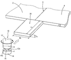
- FIG. 1 shows one form on the welding start end side when the friction stir welding method according to the present invention is carried out.
- the first member 2 and the second member 4 are abutted at their plate-like portions, and a friction stir welding operation is performed on the abutting portion 6.
- the first and second members 2 and 4 are joined to each other to obtain an integrally joined product.
- the first and second members 2 and 4 as the materials to be joined are separately separated from each other as a difficult-to-join material, such as an aluminum alloy casting, or a JIS aluminum alloy name of 2000 series (Al-Cu series), It is made of any one of 4000 series (Al—Si series), 5000 series (Al—Mg series), and 7000 series (Al—Zn—Mg series) aluminum alloy materials,
- the second members 2 and 4 may be made of the same material or different materials.
- an aluminum alloy casting it has a plate-like part obtained by casting an aluminum alloy indicated by a symbol in which a numeral and an alphabet are added next to AC in JIS designation by a normal casting method.
- a casting or a casting having a plate-like portion obtained by die casting using an aluminum alloy indicated by a symbol having a numeral next to ADC in JIS name will be used.
- the above 2000 series, 4000 series, 5000 series to 7000 series aluminum alloy materials are used in the form of various wrought materials having plate-like portions such as rolled plate materials and extruded materials.
- a rotary tool 10 as shown in FIG. 1 is used for friction stir welding of the abutting portion 6 which is a joining portion of the first member 2 and the second member 4. That is, the rotary tool 10 is a bobbin type tool having a structure similar to that of the prior art.
- the upper shoulder member 12 and the lower shoulder member 14 having the same diameter (D) are predetermined. In a form that is coaxially opposed to each other at a distance, they are connected by a rod-like probe 16 and can be rotated integrally around an axis.
- the abutting portions 6 of the first and second members 2 and 4 are clamped from above and below by the upper shoulder surface 12a of the upper shoulder member 12 and the lower shoulder surface 14a of the lower shoulder member 14.
- the rotating probe 16 enters the abutting portion 6 so that the metal of the abutting portion 6 can be frictionally stirred and flowed so that the two members 2 and 4 can be joined to each other. It is.
- the probe 16 is directly entered into the abutting portion 6 of the first and second members 2, 4, and the abutting portion 6 extends (
- the material of the first and second members 2 and 4 is an aluminum alloy whose metal fluidity is not sufficient for the friction stir action.
- the metal does not wrap around or supply to the rear side relative to the relative traveling direction of the rotary tool 10, and a gap in which no metal is present is caused there. It is difficult to form a sound joint by forming a hole defect or a non-bonding defect that is not filled with metal, and metal with poor fluidity is formed on the surface side of the material. Is then issued, is the significant burrs at the junction will be produced.
- friction stir welding is performed in order to eliminate joint defects at the joint start end portion and to suppress the occurrence of significant burrs in the joint.
- a material made of a specific aluminum alloy material in which the metal easily flows is used as the start tab member 20, and is used as an end surface on the joining start end side in the joined portion (butting portion 6) of the first and second members 2, 4.
- the probe 16 of the bobbin type rotary tool 10 is caused to enter the joined portion (butting portion 6) of the first and second members 2 and 4 through the start tab member 20 by being in contact with each other.
- the butt portion 6 is line-joined by being moved in the joining direction.
- start tab member 20 brought into contact with the end face on the joining start end side
- a 1000 series aluminum alloy, a 3000 series aluminum alloy, a 6000 series aluminum alloy, or an 8000 series which is an aluminum alloy of the JIS name.
- a member made of an aluminum alloy is used in an appropriate shape and size. In general, a member having a rectangular shape as shown in the figure is preferably used.
- any of the above-described specific aluminum alloys that give the starting tab material 20 exhibit good fluidity of the metal during friction stirring.
- the metal of the starting tab member 20 easily flows and wraps around the rear side in the traveling direction (joining direction), and can be filled in the rear side of the metal, thereby causing any defect portion where no metal exists. Instead, the rotary tool 10 moves and further enters the abutting portion 6 of the first and second members 2 and 4.
- FIG. 2 shows a form in which the rotary tool 10 is moved from the start tab member 20 to the abutting portion 6 while performing frictional stirring.
- the rotary tool 10 is being rotated about its axis.
- the first and second members 2, 4 are abutted while entering the start tab member 20 from the ends of the starting tab member 20 opposite to the first and second members 2, 4 and friction stir. It is relatively moved forward toward the portion 6. That is, the end portion of the start tab member 20 is pushed into a gap (see FIG. 1) between the upper shoulder surface 12a of the upper shoulder member 12 and the lower shoulder surface 14a of the lower shoulder member 14 in the rotary tool 10.
- the probe 16 enters the start tab member 20 and is caused by the gap between the shoulder surfaces 12a, 14a of the two shoulder members 12, 14 which are made somewhat narrower than the plate thickness of the start tab member 20.
- the start tab member 20 is frictionally agitated by the rotation of the two shoulder members 12 and 14 and the probe 16 while receiving the clamping action by the two shoulder members 12 and 14.
- the starting tab member 20 has a predetermined aluminum alloy with good metal fluidity. From the material, the metal easily turns around to the rear side in the moving direction of the rotary tool 10, and there is no defect that is not filled with metal, and a healthy friction stirrer is formed. It becomes.
- the rotary tool 10 passes through the start tab material 20 and reaches the abutting portion 6 of the first and second members 2, 4.
- the metal generated from the start tab material 20 is filled on the rear side in the moving direction of the rotary tool 10, and there is any gap.
- the metal generated from the first and second members 2 and 4 is effectively moved rearward in the moving direction of the rotary tool 10 as the two shoulder members 12 and 14 and the probe 16 rotate. As a result, even if the first and second members 2 and 4 enter the abutting portion 6, the metal is continuously filled to the rear side in the moving direction of the rotary tool 10.
- first member 2 and the second member 4 subjected to the friction stir welding operation are generally abutted at the same thickness (t) of the plate-like portion to form the abutting portion 6. And even if it exists in the thickness (Ts) of the start tab material 20 made to contact
- the length (Ls) in the direction in which the butting portion 6 extends is generally four times the diameter (D) of the shoulder members 12 and 14 in the rotary tool 10, in other words, the diameter of each shoulder surface 12a and 14a.
- the width (Ws) in the direction perpendicular to the length (Ls) in the joining direction is the length of the shoulder members 12 and 14 of the rotary tool 10. It is desirable that the size is twice or more the diameter (D).
- the size and shape of the start tab material 20 are appropriately selected so as to satisfy the conditions of the length (Ls) and the width (Ws).
- the diameter (d) of the probe 16 in the rotary tool 10 is preferably at least twice the thickness (Ts) of the starting tab member 20, which makes the friction stir welding operation according to the present invention more advantageous. It can be made to progress.
- the shoulder members 12 and 14 of the rotary tool 10 have the same diameter.
- the diameters of the shoulder members 12 and 14 can be varied to some extent.
- the upper shoulder member It is desirable to make the diameter of 12 larger than the diameter of the lower shoulder member 14, and the diameter (D) of the shoulder members 12, 14 is the diameter of the larger shoulder surface.
- the shoulder members 12 and 14 generally have a diameter (D) that is at least 4 mm larger than the diameter (d) of the probe 16.
- the diameter of the smaller shoulder member (14) is smaller than the value obtained by adding 2 mm to the diameter (d) of the probe 16. It is set not to be.
- a plate-like end tab material 22 made of the same aluminum alloy material as that of the previous start tab material 20 is disposed, and the rotary tool 10 A configuration in which the probe 16 is guided from the abutting portion 6 to the end tab member 22 to finish the friction stir welding is advantageously employed. It becomes a.
- An alloy or a plate material made of an 8000 series aluminum alloy is used, and this is brought into contact with the end face on the end side of joining at the butting portion 6 (joined part) of the first and second members 2 and 4.
- the probe 16 of the rotary tool 10 to be guided to the end tab member 22, the metal adhering around the probe 16 of the rotary tool 10 is removed while the end tab member 22 is moved. You will be tempted.
- the rotary tool 10 clamps the butting portions 6 of the first and second members 2, 4 between the upper shoulder member 12 and the lower shoulder member 14, After the abutting portion 6 is friction stir welded by being moved relative to the first and second members 2 and 4 along the abutting portion 6, an end tab material is formed from the end of the abutting portion 6. 22, the rotating tool 10 is rotated as it is, and the end tab member 22 is allowed to pass through the end tab member 22 while frictionally stirring the metal of the end tab member 22. In the friction stir welding operation 6, the metal adhered around the probe 16 of the rotary tool 10 is effectively removed by the stirring of the metal when passing through the end tab material 22.
- the rotating tool 10 that is detached from the end tab member 22 and taken out outwards has almost no adhered metal, and therefore, a troublesome metal removal operation from the rotating tool 10 is performed. This is no longer necessary, and such a rotary tool 10 can be used repeatedly as it is for the next friction stir welding operation.
- terminus tab material 22 will be suitably selected in order to achieve the arrangement
- the width (We) is configured to be at least twice the diameter (D) of the shoulder members 12 and 14.
- the thickness (Te) of the end tab member 22 is configured to be 1 ⁇ 2 or less of the diameter (d) of the probe 16 in the rotary tool 10.
- the first member 2 is composed of two shoulder members 12 and 14 arranged at predetermined intervals in the axial direction of the rod-shaped probe.
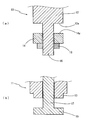
- Various known rotary tools that can be friction stir welded by rotation of the rotary tool while pinching the butting portion (bonded portion) 6 with the second member 4 can be used as appropriate, for example, 5 (a), a tool having a structure in which the upper shoulder member 12 and the lower shoulder member 14 are concentrically connected and fixed by the probe 16 in a form in which the upper shoulder member 12 and the lower shoulder member 14 are opposed to each other with a predetermined interval.
- a so-called bobbin tool 10 is used.
- the lower shoulder member 14 is screwed to the probe 16 so that the length of the probe 16 is defined, and the lower shoulder member 14 is further tightened by a locking nut 18 screwed. Is fixed so that it does not move.
- the probe 17 is coaxially fixed to the lower shoulder member 15 of the two shoulder members, and the probe is fixed to the upper shoulder member 13. It is also possible to use a so-called self-reacting tool 11 that is structured so that the distance between the upper shoulder member 13 and the lower shoulder member 15 can be changed.
- the gap between the two shoulder members 12, 14; 13, 15 is such a butt so that an appropriate clamping action can be applied to the butt portion 6 as a joining site.
- the thickness of the portion 6 is configured to be somewhat smaller. Further, in the self-reacting tool 11, there is no problem even if the upper shoulder member 13 and the lower shoulder member 15 are rotated in the same direction or in different directions.
- the friction stir welding operation using the rotary tool 10 according to the present invention such as the bobbin tool 10 and the self-reacting tool 11 is performed at the thickness of the joining portion, for example, the thickness of the first and second members 2 and 4 ( In general, t) is advantageously employed when it is 2 mm or more.
- the upper limit of the thickness (t) of the first and second members 2 and 4 is generally about 10 mm.
- the friction stir welding operation is performed on the butt portion 6 between the first member 2 and the second member 4 so that the members 2 and 4 are line-joined.
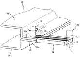
- a plate-like flange portion 32 a of an upper member 32 (first member) having a hat-shaped cross section that gives the hollow structure 30, and a lower member 34 ( The present invention can also be applied to a system in which the plate-like flange portion 34a of the second member) is overlapped and a friction stir welding operation is performed on the overlapping portion 36.
- the rotary tool 10 passes through the starting tab member 24 and is led to the overlapping portion 36 of the plate-like flange portions 32a and 34a, and the friction stir welding is advanced in the extending direction of the overlapping portion 36. It is like that. Accordingly, the rotary tool 10 is rotated around its axis, enters the overlapping portion 36 from the start tab member 24, and is turned at a right angle so as to be relative to the extending direction of the overlapping portion 36. In this case, the friction stir welding of the overlapping portion 36 is advanced through the start tab member 24 according to the present invention. As in the case of, a healthy friction stir joint 38 is advantageously formed.
- the start tab material 24 is brought into contact with the side surface in the width direction of the overlapping portion 36 of the flange portions 32 a and 34 a.
- the start tab member (24) is brought into contact with the longitudinal end face of the tool, and the friction stir welding operation is linearly performed by the rotary tool 10 in the direction in which the overlapping portion 36 extends from the start tab member 24. In this case, it is possible to enjoy the same effect.
- the start tab member 20 is fixed to the joining start end side by the metal subjected to frictional stirring, and in some cases, the end tab member 22 is also fixed to the joining end end side.
- the start tab member 20 and the end tab member 22 can be mechanically easily folded, and a joined product having a sound joint portion 8 can be easily realized. Accordingly, after removing the tab members 20 and 22, the metal fixed to the end faces of the first and second members 2 and 4 is removed by a cutting machine such as a grinder to finish the end faces. This is also advantageously employed in the present invention.
- the present invention is a technique for joining a wrought material such as a plate material or an extruded material or a casting to manufacture a large material.
- the joined product thus obtained can be advantageously used as a structural member such as a railway vehicle structure or an automobile subframe, and exhibits its characteristics. To do.
- the plate thickness (Ts), the length in the joining direction A plate-like start tab member (20) made of various aluminum materials having a thickness (Ls) and a width (Ws) in a direction perpendicular to the joining direction is butted as shown in FIG. , 4) and fixed and held on the table.
- the starting tab member (20) is passed through the lengthwise direction while being frictionally stirred, and then entered into the abutting portion (6) of the two members (2, 4). Further, the abutting portion (6 ) In the extending direction of the bobbin tool (10) By moving, it was carried out friction stir welding of the butted portion (6).
- Thickness (t) 4.0 mm, plate width: 300 mm, length: 5000 mm, material: 5454-O, using two aluminum rolled sheets as the first and second members (2, 4) Were fixed in the width direction and fixed and held on a table provided with a gap so as to be positioned below the butting portion (6). And with respect to the end part of the joining start end side in the butting part (6) of these two plate materials (2, 4), various joining direction lengths (Ls) shown in the following Table 3 are perpendicular thereto. Thickness (Ts) having width direction length (Ws) in direction: 4.0 mm, aluminum material: Start tab material (20) made of 1200 is abutted and similar to two plates (2, 4) , Fixed and held respectively.
- Example 2 As an example of a rotating jig, except that the axial length of the probe (16), which is the distance between the upper shoulder surface (12a) and the lower shoulder surface (14a), was changed to 3.7 mm.
- the same friction stir welding operation as in Example 1 was performed using a bobbin tool (10) having the same dimensions as 1, and the results are also shown in Table 3 below.
- the length (Ls) in the joining direction of the start tab member (20) is four times or more the diameter (D) of the shoulder member (12, 14) in the bobbin tool (10).
- the width (Ws) in the direction perpendicular to the joining direction is twice or more the diameter (D) of the shoulder member (12, 14)
- the soundness of the friction stir welding part (8) can be improved. It can be advantageously increased.
- the material of the finished tab material (22) is 1000 series aluminum alloy, 3000 series aluminum alloy, 6000 series aluminum alloy or 8000 series.
- the aluminum alloy metal adhesion to the bobbin tool (10) can be effectively suppressed or prevented, so that the bobbin tool (10) after the friction stir welding operation has been completed. It was confirmed that the following two members (2, 4) can be used for the friction stir welding operation.
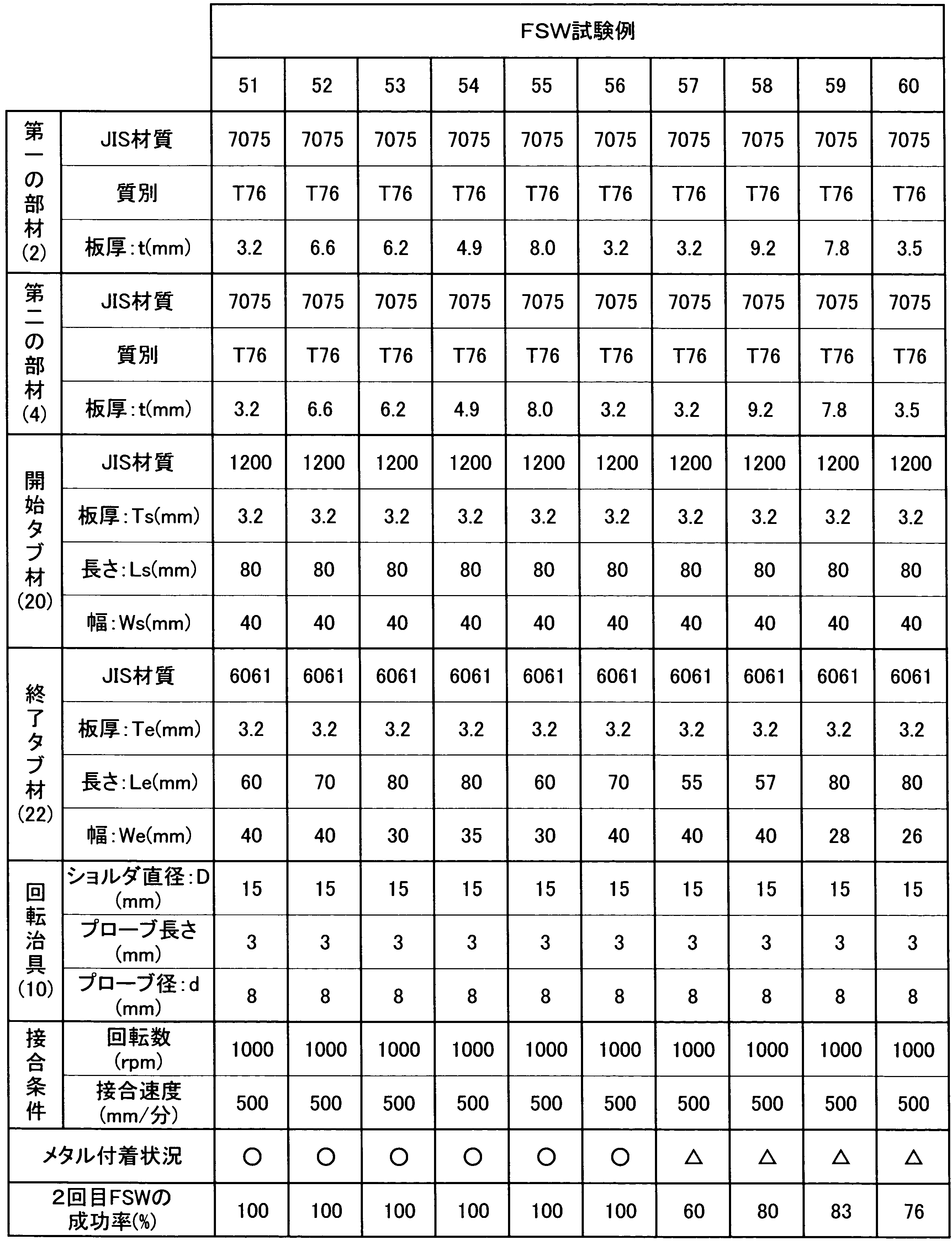
- Example 4 In the friction stir welding operation according to FSW Test Example 31 in Example 3, the thickness (t) of the first and second members (2, 4) and the thickness (Ts) of the start tab material (20) are changed. Example 3 except that the dimensions of the joining tab length (22) in the joining direction length (Le) and the width (We) in the direction perpendicular thereto were changed as shown in Table 6 below. Similarly, the friction stir operation was performed, and after the bobbin tool (10) passed through the end tab material (22), the friction stir welding operation was completed. And the metal adhesion state of the bobbin tool (10) after such friction stir welding operation was completed was observed and evaluated in the same manner as in Example 3. The results are also shown in Table 6 below.
- the length (Le) in the joining direction of the end tab member (22) is four times or more the diameter (D) of the shoulder member (12, 14) in the bobbin tool (10).
- the width (We) in the direction perpendicular to the joining direction is at least twice the diameter (D) of the shoulder member (12, 14), so that the metal adheres to the bobbin tool (10).
- Second member 4 Second member 6 Abutting portion 8 Friction stir welding portion 10 Rotating tool (bobbin tool) 11 Self-reacting tool 12, 13 Upper shoulder member 14, 15 Lower shoulder member 12a Upper shoulder surface 14a Lower side Shoulder surface 16, 17 Probe 18 Stop nut 20, 24 Start tab material 22 End tab material 30 Hollow structure 32 Upper member 32a, 34a Flange portion 34 Lower member 36 Superposed portion
Landscapes
- Engineering & Computer Science (AREA)
- Mechanical Engineering (AREA)
- Pressure Welding/Diffusion-Bonding (AREA)
Abstract
Description
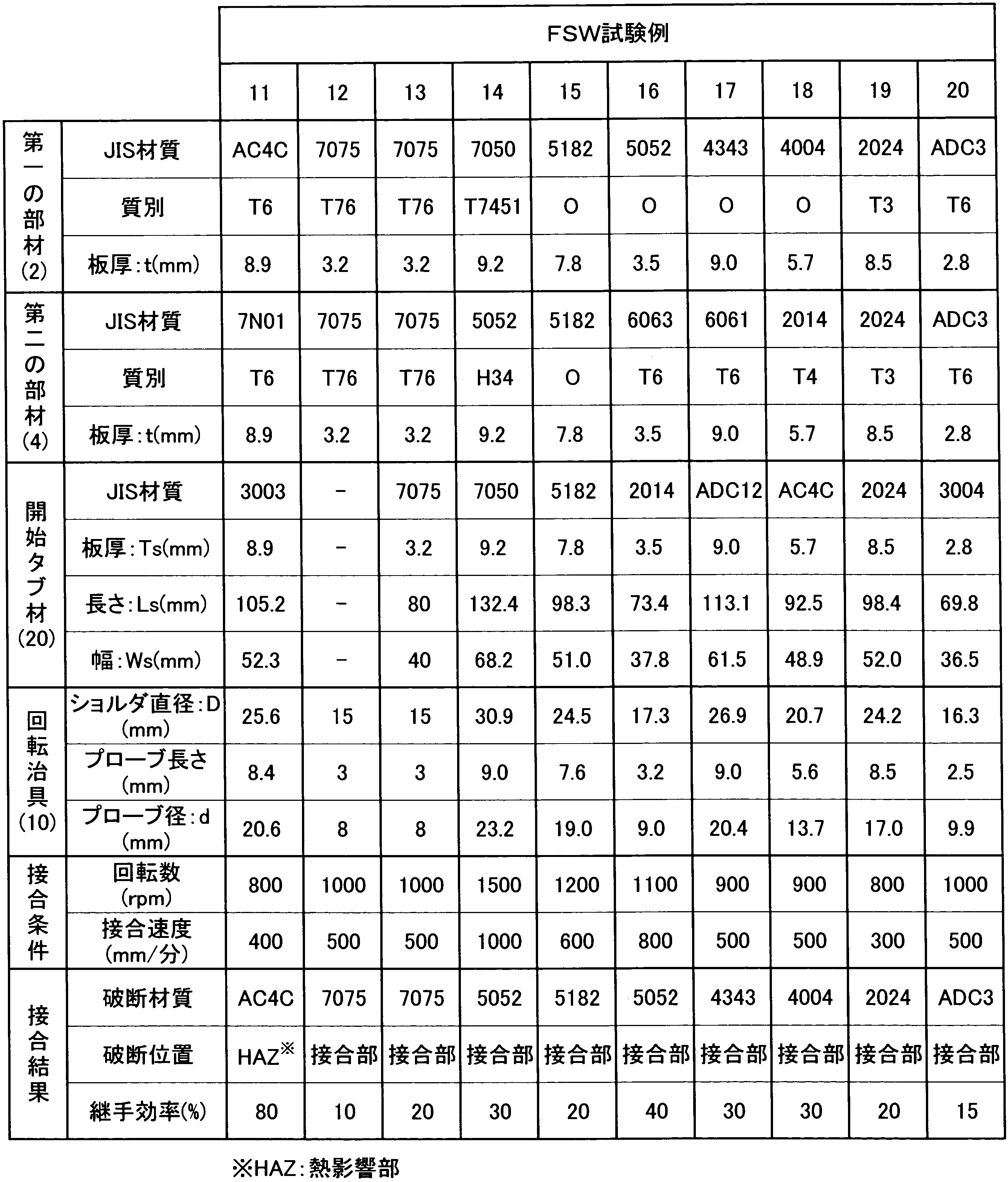
板厚(t):2.8~9.2mm、板幅:300mm、長さ:5000mmの寸法を有する、下記表1~2に示される各種アルミニウム材質の板状の第一の部材(2)及び第二の部材(4)を用い、それらの板幅方向に対向する側面を突き合わせて、その突合せ部(6)の下方に位置するように間隙を設けてなるテーブル上に、それぞれ固定、保持せしめた。また、それら突き合わされた2つの部材(2,4)の突合せ部(6)の接合開始端側の端部には、下記表1~2に示される如き、板厚(Ts)、接合方向長さ(Ls)及び接合方向に直角な方向の幅(Ws)を有する各種アルミニウム材質の板状の開始タブ材(20)を用いて、図1に示される如く突き合わせ、先の2つの部材(2,4)と同様にテーブル上に固定、保持せしめた。

板厚(t):4.0mm、板幅:300mm、長さ:5000mm、材質:5454-Oのアルミニウム圧延板材の2枚を、第一及び第二の部材(2,4)として用い、それらを幅方向に突き合わせて、その突合せ部(6)の下方に位置するように間隙を設けてなるテーブル上に、それぞれ固定、保持せしめた。そして、それら2枚の板材(2,4)の突合せ部(6)における接合開始端側の端部に対して、下記表3に示される各種の接合方向長さ(Ls)と、それに直角な方向の幅方向長さ(Ws)とを有する板厚(Ts):4.0mm、アルミニウム材質:1200からなる開始タブ材(20)を突き合わせて、2枚の板材(2,4)と同様に、それぞれ固定、保持せしめた。

実施例1におけるFSW試験例1~20と同様にして、摩擦撹拌接合操作を開始する一方、2枚の板材(2,4)の突合せ部(6)における接合終了端側の端面に対して、下記表4~5に示される、接合方向長さ(Le)、接合方向に直角な方向の幅(We)及び板厚(Te)を有する各種アルミニウム材質の板状の終了タブ材(22)を当接せしめて、かかる突合せ部(6)を全長に亘って移動したボビンツール(10)が、図4に示される如く、突合せ部(6)の終端から終了タブ材(22)に導かれ、次いで、かかる終了タブ材(22)を接合方向に導かれた後、摩擦撹拌接合が終了せしめられるようにした。そして、そのような摩擦撹拌接合の終了に際してのボビンツール(10)におけるメタルの付着の程度を観察する一方、そのような摩擦撹拌接合操作の終了したボビンツール(10)をそのまま用い、再度同様な摩擦撹拌接合操作を実施して、その2回目の摩擦撹拌接合操作の成功率を求め、その結果を、下記表3に併せ示した。なお、メタルの付着の程度の評価に際しては、○:メタルの付着が殆ど認められない、△:メタルの付着が認められる、×:メタルの付着が著しい、との基準を採用した。

前記実施例3におけるFSW試験例31に係る摩擦撹拌接合操作において、第一及び第二の部材(2,4)の板厚(t)及び開始タブ材(20)の板厚(Ts)を変化させると共に、終了タブ材(22)の接合方向長さ(Le)と、それに直角な方向の幅(We)の寸法を、下記表6に示されるように変えたこと以外は、実施例3と同様にして、摩擦撹拌操作を実施し、そしてボビンツール(10)が終了タブ材(22)を通過した後、摩擦撹拌接合操作が終了せしめられるようにした。そして、そのような摩擦撹拌接合操作が終了した後におけるボビンツール(10)のメタル凝着状況を観察して、実施例3と同様に評価し、その結果を、下記表6に併せ示した。
6 突合せ部 8 摩擦撹拌接合部
10 回転工具(ボビンツール) 11 セルフリアクティングツール
12,13 上側ショルダ部材 14,15 下側ショルダ部材
12a 上側ショルダ面 14a 下側ショルダ面
16,17 プローブ 18 止めナット
20,24 開始タブ材 22 終了タブ材
30 中空構造体
32 上側部材 32a,34a フランジ部
34 下側部材 36 重合せ部
Claims (10)
- アルミニウム合金製鋳物、2000系アルミニウム合金材、4000系アルミニウム合金材、5000系アルミニウム合金材、及び7000系アルミニウム合金材からなる群より選ばれた同種又は異種材質の第一の部材と第二の部材との接合部位を、回転工具におけるロッド状のプローブの軸方向に所定の間隔をおいて配した二つのショルダ部材にて挟圧しつつ、かかる回転工具の回転によって、それら二つのショルダ部材と共に回転せしめられる前記プローブを、接合方向に移動させることにより、前記第一の部材と前記第二の部材との接合部位を摩擦撹拌接合するに際し、
前記第一及び第二の部材の接合部位における接合開始端側の端面に、1000系アルミニウム合金、3000系アルミニウム合金、6000系アルミニウム合金、又は8000系アルミニウム合金からなる開始タブ材を当接せしめ、該開始タブ材を通じて、前記回転工具のプローブが、それら第一及び第二の部材の前記接合部位に進入するようにしたことを特徴とする摩擦撹拌接合方法。 - 前記開始タブ材が、前記回転工具による前記第一及び第二の部材の接合方向において前記ショルダ部材の直径の4倍以上の長さを有していると共に、該接合方向に直角な方向において該ショルダ部材の直径の2倍以上の幅を有している板材である請求項1に記載の摩擦撹拌接合方法。
- 前記回転工具のプローブの直径が、前記開始タブ材の厚さの2倍以上である請求項1又は請求項2に記載の摩擦撹拌接合方法。
- 前記第一の部材と前記第二の部材とを突き合わせ、その突合せ部位に対して、前記摩擦撹拌接合が実施される請求項1乃至請求項3の何れか一つに記載の摩擦撹拌接合方法。
- 前記第一の部材と前記第二の部材とを重ね合わせ、その重合せ部位に対して、前記摩擦撹拌接合が実施される請求項1乃至請求項3の何れか一つに記載の摩擦撹拌接合方法。
- 前記回転工具が、前記プローブに対して、前記二つのショルダ部材を所定の間隔をおいて固定的に取り付けてなるボビンツールである請求項1乃至請求項5の何れか一つに記載の摩擦撹拌接合方法。
- 前記回転工具が、前記プローブに対して、前記二つのショルダ部材のうちの一方を固定し、他方を該プローブの軸方向に移動可能として、それら二つのショルダ部材の間隔が変更され得るようにしたセルフリアクティングツールである請求項1乃至請求項5の何れか一つに記載の摩擦撹拌接合方法。
- 前記第一の部材と前記第二の部材との接合部位における接合終了端側の端面に対して、1000系アルミニウム合金、3000系アルミニウム合金、6000系アルミニウム合金、又は8000系アルミニウム合金からなる終了タブ材を当接せしめ、前記回転工具のプローブが、前記第一及び第二の部材の接合部位から該終了タブ材に導かれて、前記摩擦撹拌接合が終了せしめられるようにした請求項1乃至請求項7の何れか一つに記載の摩擦撹拌接合方法。
- 前記終了タブ材が、前記回転工具による前記第一及び第二の部材の接合方向において前記ショルダ部材の直径の4倍以上の長さを有していると共に、該接合方向に直角な方向において該ショルダ部材の直径の2倍以上の幅を有している板材である請求項8に記載の摩擦撹拌接合方法。
- 前記終了タブ材が、前記回転工具におけるプローブの直径の1/2以下の厚さとされている請求項8又は請求項9に記載の摩擦撹拌接合方法。
Priority Applications (4)
| Application Number | Priority Date | Filing Date | Title |
|---|---|---|---|
| CA2921220A CA2921220C (en) | 2013-08-13 | 2014-08-06 | Friction stir welding method |
| CN201480044386.4A CN105473269B (zh) | 2013-08-13 | 2014-08-06 | 搅拌摩擦焊接方法 |
| MX2016001820A MX2016001820A (es) | 2013-08-13 | 2014-08-06 | Metodo de soldadura por friccion-agitacion. |
| US15/014,338 US9937588B2 (en) | 2013-08-13 | 2016-02-03 | Friction stir welding method |
Applications Claiming Priority (4)
| Application Number | Priority Date | Filing Date | Title |
|---|---|---|---|
| JP2013-168060 | 2013-08-13 | ||
| JP2013168061A JP6043692B2 (ja) | 2013-08-13 | 2013-08-13 | 摩擦撹拌接合方法 |
| JP2013168060A JP6133165B2 (ja) | 2013-08-13 | 2013-08-13 | 摩擦撹拌接合方法 |
| JP2013-168061 | 2013-08-13 |
Related Child Applications (1)
| Application Number | Title | Priority Date | Filing Date |
|---|---|---|---|
| US15/014,338 Continuation US9937588B2 (en) | 2013-08-13 | 2016-02-03 | Friction stir welding method |
Publications (1)
| Publication Number | Publication Date |
|---|---|
| WO2015022893A1 true WO2015022893A1 (ja) | 2015-02-19 |
Family
ID=52468280
Family Applications (2)
| Application Number | Title | Priority Date | Filing Date |
|---|---|---|---|
| PCT/JP2014/070732 Ceased WO2015022893A1 (ja) | 2013-08-13 | 2014-08-06 | 摩擦撹拌接合方法 |
| PCT/JP2014/070733 Ceased WO2015022894A1 (ja) | 2013-08-13 | 2014-08-06 | 摩擦撹拌接合方法 |
Family Applications After (1)
| Application Number | Title | Priority Date | Filing Date |
|---|---|---|---|
| PCT/JP2014/070733 Ceased WO2015022894A1 (ja) | 2013-08-13 | 2014-08-06 | 摩擦撹拌接合方法 |
Country Status (5)
| Country | Link |
|---|---|
| US (2) | US9931711B2 (ja) |
| CN (2) | CN105531069B (ja) |
| CA (2) | CA2921320C (ja) |
| MX (2) | MX2016001819A (ja) |
| WO (2) | WO2015022893A1 (ja) |
Families Citing this family (16)
| Publication number | Priority date | Publication date | Assignee | Title |
|---|---|---|---|---|
| CN105026096B (zh) * | 2013-04-25 | 2017-11-21 | 三菱重工业株式会社 | 摩擦搅拌接合用工具、摩擦搅拌接合装置及接合材料的制造方法 |
| JP6655868B2 (ja) | 2014-08-28 | 2020-03-04 | 三菱重工エンジニアリング株式会社 | 摩擦撹拌接合用のエンドタブ、及び接合材の製造方法 |
| CN107335909A (zh) * | 2017-08-17 | 2017-11-10 | 沈阳富创精密设备有限公司 | 一种半导体行业铝合金中、厚板焊接方法 |
| US10688592B1 (en) * | 2017-09-05 | 2020-06-23 | United Launch Alliance L.L.C | Friction stir welding of aluminum alloys |
| JP7086773B2 (ja) * | 2018-07-25 | 2022-06-20 | 株式会社東芝 | 溶接方法、溶接物の製造方法、及び溶接物 |
| CN109407781A (zh) * | 2018-10-31 | 2019-03-01 | 天津七所精密机电技术有限公司 | 基于两级相变一级液冷散热技术的加固机箱 |
| CN109551100A (zh) * | 2019-01-23 | 2019-04-02 | 李铁骑 | 气瓶焊接方法及气瓶结构 |
| JP7082329B2 (ja) * | 2019-02-01 | 2022-06-08 | 株式会社Ihi | き裂補修方法 |
| JP6698927B1 (ja) * | 2019-08-22 | 2020-05-27 | 株式会社フルヤ金属 | 金属系筒材の製造方法及びそれに用いられる裏当て治具 |
| KR102722470B1 (ko) * | 2019-09-26 | 2024-10-25 | 히다치 아스테모 가부시키가이샤 | 로드의 제조 방법 |
| CN111014937B (zh) * | 2019-11-25 | 2021-08-03 | 长春城际轨道客车配件有限公司 | 基于搅拌摩擦焊的金属结构件的制作方法 |
| DE102019220326A1 (de) * | 2019-12-20 | 2021-06-24 | Robert Bosch Gmbh | Verfahren zur Herstellung eines Hydraulikgehäuses, Hydraulikgehäuse |
| CN111660003B (zh) * | 2020-06-22 | 2021-08-03 | 浙江最成半导体科技有限公司 | 一种溅射靶材焊接方法 |
| EP4707715A2 (en) | 2021-01-21 | 2026-03-11 | Parker-Hannifin Corporation | Heat exchanger with progressive divided flow circuit, structural load bearing design |
| CN113579460B (zh) * | 2021-07-22 | 2022-12-02 | 广东省科学院中乌焊接研究所 | 一种去除搅拌头金属粘料的方法 |
| US12576455B2 (en) * | 2022-10-20 | 2026-03-17 | Standex International Corporation | Friction stir welding process for large metallic components |
Citations (6)
| Publication number | Priority date | Publication date | Assignee | Title |
|---|---|---|---|---|
| JPH0471634B2 (ja) * | 1986-06-03 | 1992-11-16 | Sky Aluminium | |
| JPH1071477A (ja) * | 1996-05-31 | 1998-03-17 | Boeing Co:The | 摩擦スター溶接工具および方法 |
| JP2002248582A (ja) * | 2001-02-23 | 2002-09-03 | Hitachi Ltd | 摩擦攪拌接合方法 |
| JP2005074518A (ja) * | 2003-08-29 | 2005-03-24 | Boeing Co:The | 加工物に摩擦攪拌溶接継手を形成するための工具及び方法 |
| JP2007061877A (ja) * | 2005-09-01 | 2007-03-15 | Sumitomo Light Metal Ind Ltd | 円筒状物品の製造方法 |
| JP4004259B2 (ja) * | 2001-09-25 | 2007-11-07 | 住友軽金属工業株式会社 | 摩擦攪拌接合方法 |
Family Cites Families (16)
| Publication number | Priority date | Publication date | Assignee | Title |
|---|---|---|---|---|
| GB9125978D0 (en) | 1991-12-06 | 1992-02-05 | Welding Inst | Hot shear butt welding |
| JP2003154471A (ja) | 2001-11-20 | 2003-05-27 | Hitachi Ltd | 摩擦攪拌接合用中空形材 |
| JP3510612B2 (ja) * | 2001-11-27 | 2004-03-29 | 川崎重工業株式会社 | 摩擦撹拌接合方法 |
| JP3735296B2 (ja) | 2001-12-13 | 2006-01-18 | 三菱重工業株式会社 | 摩擦撹拌接合装置 |
| US7000303B2 (en) * | 2002-10-24 | 2006-02-21 | The Boeing Company | Method of repairing a crack in a component utilizing friction stir welding |
| JP3865686B2 (ja) * | 2002-11-05 | 2007-01-10 | 住友軽金属工業株式会社 | 摩擦撹拌接合方法及びそれに用いられるタブ板 |
| JP4352814B2 (ja) * | 2003-08-27 | 2009-10-28 | 日本軽金属株式会社 | 摩擦攪拌接合方法 |
| WO2005030419A2 (en) * | 2003-09-25 | 2005-04-07 | Smith International, Inc. | Friction stir welding improvements for metal matrix composites, ferrous alloys, non-ferrous alloys, and superalloys using a superabrasive tool |
| US7380321B2 (en) * | 2006-03-28 | 2008-06-03 | The Boeing Company | Machining technique with selective and localized placement of tooling material |
| CN102267007B (zh) * | 2006-10-02 | 2015-11-25 | 日本轻金属株式会社 | 接合方法 |
| JP2008188664A (ja) * | 2007-02-08 | 2008-08-21 | Nippon Light Metal Co Ltd | 接合方法 |
| JP2009018312A (ja) | 2007-07-10 | 2009-01-29 | Sumitomo Light Metal Ind Ltd | 摩擦撹拌接合装置と、該摩擦撹拌接合装置を利用した異種金属同士の差厚テーラードブランク材の製造方法 |
| US9541224B2 (en) * | 2009-08-17 | 2017-01-10 | Global Tubing, Llc | Method of manufacturing coiled tubing using multi-pass friction stir welding |
| JP2011218363A (ja) * | 2010-04-02 | 2011-11-04 | Furukawa-Sky Aluminum Corp | 摩擦攪拌接合方法 |
| JP5690331B2 (ja) * | 2010-04-02 | 2015-03-25 | 本田技研工業株式会社 | 異種材接合体及びその接合方法 |
| CN102873454B (zh) * | 2012-09-18 | 2014-09-10 | 西北工业大学 | 一种多层金属带的焊接方法 |
-
2014
- 2014-08-06 CA CA2921320A patent/CA2921320C/en active Active
- 2014-08-06 MX MX2016001819A patent/MX2016001819A/es unknown
- 2014-08-06 MX MX2016001820A patent/MX2016001820A/es unknown
- 2014-08-06 CA CA2921220A patent/CA2921220C/en active Active
- 2014-08-06 CN CN201480043947.9A patent/CN105531069B/zh active Active
- 2014-08-06 WO PCT/JP2014/070732 patent/WO2015022893A1/ja not_active Ceased
- 2014-08-06 WO PCT/JP2014/070733 patent/WO2015022894A1/ja not_active Ceased
- 2014-08-06 CN CN201480044386.4A patent/CN105473269B/zh active Active
-
2016
- 2016-02-03 US US15/014,366 patent/US9931711B2/en active Active
- 2016-02-03 US US15/014,338 patent/US9937588B2/en active Active
Patent Citations (6)
| Publication number | Priority date | Publication date | Assignee | Title |
|---|---|---|---|---|
| JPH0471634B2 (ja) * | 1986-06-03 | 1992-11-16 | Sky Aluminium | |
| JPH1071477A (ja) * | 1996-05-31 | 1998-03-17 | Boeing Co:The | 摩擦スター溶接工具および方法 |
| JP2002248582A (ja) * | 2001-02-23 | 2002-09-03 | Hitachi Ltd | 摩擦攪拌接合方法 |
| JP4004259B2 (ja) * | 2001-09-25 | 2007-11-07 | 住友軽金属工業株式会社 | 摩擦攪拌接合方法 |
| JP2005074518A (ja) * | 2003-08-29 | 2005-03-24 | Boeing Co:The | 加工物に摩擦攪拌溶接継手を形成するための工具及び方法 |
| JP2007061877A (ja) * | 2005-09-01 | 2007-03-15 | Sumitomo Light Metal Ind Ltd | 円筒状物品の製造方法 |
Also Published As
| Publication number | Publication date |
|---|---|
| CN105531069A (zh) | 2016-04-27 |
| US20160151855A1 (en) | 2016-06-02 |
| CA2921320A1 (en) | 2015-02-19 |
| MX2016001819A (es) | 2016-05-24 |
| CN105531069B (zh) | 2018-06-12 |
| CA2921320C (en) | 2021-08-03 |
| CN105473269B (zh) | 2018-05-18 |
| WO2015022894A1 (ja) | 2015-02-19 |
| MX2016001820A (es) | 2016-05-24 |
| US20160167162A1 (en) | 2016-06-16 |
| CN105473269A (zh) | 2016-04-06 |
| US9931711B2 (en) | 2018-04-03 |
| CA2921220C (en) | 2021-07-13 |
| CA2921220A1 (en) | 2015-02-19 |
| US9937588B2 (en) | 2018-04-10 |
Similar Documents
| Publication | Publication Date | Title |
|---|---|---|
| WO2015022893A1 (ja) | 摩擦撹拌接合方法 | |
| JP3459193B2 (ja) | 摩擦攪拌接合部の補修方法および鉄道車両の製作方法 | |
| EP2067563A1 (en) | Friction-stir weldments and systems and methods for producing the same | |
| JP2016150380A (ja) | 接合方法及び複合圧延材の製造方法 | |
| JP3297845B2 (ja) | アルミニウム部材の接合方法 | |
| US8763882B2 (en) | Friction stir welding method for metal material and metal material welded body obtained thereby | |
| JP5194906B2 (ja) | 接合方法 | |
| JP6133165B2 (ja) | 摩擦撹拌接合方法 | |
| JP3781840B2 (ja) | アルミニウム材と異種金属材との接合方法 | |
| JPH0481288A (ja) | 鋼系材料とアルミニウム系材料との接合方法 | |
| JP3283434B2 (ja) | 摩擦攪拌接合用治具及びそれを用いた摩擦攪拌接合方法 | |
| JP6414327B2 (ja) | 接合方法 | |
| JP6043692B2 (ja) | 摩擦撹拌接合方法 | |
| WO2005053890A2 (en) | Method for metal and alloy joining using bulk friction stir welding | |
| JP2002248582A (ja) | 摩擦攪拌接合方法 | |
| JP3886596B2 (ja) | リブ付きアルミニウム製品の製造法 | |
| JP2013255946A (ja) | 接合方法 | |
| JP2003112272A (ja) | 摩擦撹拌接合法 | |
| JP3283433B2 (ja) | アルミニウム広幅形材の製造方法 | |
| JP3081799B2 (ja) | アルミニウム材の接合方法 | |
| JP2011101891A (ja) | 接合方法 | |
| JP5509798B2 (ja) | 接合方法 | |
| JP2008194732A (ja) | 接合方法 | |
| CN110325314A (zh) | 接合方法 | |
| JP5674355B2 (ja) | アルミニウム材の溶接方法 |
Legal Events
| Date | Code | Title | Description |
|---|---|---|---|
| WWE | Wipo information: entry into national phase |
Ref document number: 201480044386.4 Country of ref document: CN |
|
| 121 | Ep: the epo has been informed by wipo that ep was designated in this application |
Ref document number: 14836866 Country of ref document: EP Kind code of ref document: A1 |
|
| WWE | Wipo information: entry into national phase |
Ref document number: MX/A/2016/001820 Country of ref document: MX |
|
| ENP | Entry into the national phase |
Ref document number: 2921220 Country of ref document: CA |
|
| WWE | Wipo information: entry into national phase |
Ref document number: IDP00201600957 Country of ref document: ID |
|
| NENP | Non-entry into the national phase |
Ref country code: DE |
|
| 122 | Ep: pct application non-entry in european phase |
Ref document number: 14836866 Country of ref document: EP Kind code of ref document: A1 |