WO2015019940A1 - 端末装置 - Google Patents
端末装置 Download PDFInfo
- Publication number
- WO2015019940A1 WO2015019940A1 PCT/JP2014/070211 JP2014070211W WO2015019940A1 WO 2015019940 A1 WO2015019940 A1 WO 2015019940A1 JP 2014070211 W JP2014070211 W JP 2014070211W WO 2015019940 A1 WO2015019940 A1 WO 2015019940A1
- Authority
- WO
- WIPO (PCT)
- Prior art keywords
- terminal device
- information
- signal
- base station
- uplink
- Prior art date
Links
Images


Classifications
-
- H—ELECTRICITY
- H04—ELECTRIC COMMUNICATION TECHNIQUE
- H04W—WIRELESS COMMUNICATION NETWORKS
- H04W56/00—Synchronisation arrangements
- H04W56/004—Synchronisation arrangements compensating for timing error of reception due to propagation delay
- H04W56/0045—Synchronisation arrangements compensating for timing error of reception due to propagation delay compensating for timing error by altering transmission time
-
- H—ELECTRICITY
- H04—ELECTRIC COMMUNICATION TECHNIQUE
- H04L—TRANSMISSION OF DIGITAL INFORMATION, e.g. TELEGRAPHIC COMMUNICATION
- H04L27/00—Modulated-carrier systems
- H04L27/26—Systems using multi-frequency codes
- H04L27/2601—Multicarrier modulation systems
- H04L27/2602—Signal structure
- H04L27/2605—Symbol extensions, e.g. Zero Tail, Unique Word [UW]
- H04L27/2607—Cyclic extensions
-
- H—ELECTRICITY
- H04—ELECTRIC COMMUNICATION TECHNIQUE
- H04L—TRANSMISSION OF DIGITAL INFORMATION, e.g. TELEGRAPHIC COMMUNICATION
- H04L5/00—Arrangements affording multiple use of the transmission path
- H04L5/003—Arrangements for allocating sub-channels of the transmission path
- H04L5/0053—Allocation of signaling, i.e. of overhead other than pilot signals
-
- H—ELECTRICITY
- H04—ELECTRIC COMMUNICATION TECHNIQUE
- H04W—WIRELESS COMMUNICATION NETWORKS
- H04W16/00—Network planning, e.g. coverage or traffic planning tools; Network deployment, e.g. resource partitioning or cells structures
- H04W16/14—Spectrum sharing arrangements between different networks
-
- H—ELECTRICITY
- H04—ELECTRIC COMMUNICATION TECHNIQUE
- H04W—WIRELESS COMMUNICATION NETWORKS
- H04W76/00—Connection management
- H04W76/10—Connection setup
- H04W76/14—Direct-mode setup
-
- H—ELECTRICITY
- H04—ELECTRIC COMMUNICATION TECHNIQUE
- H04W—WIRELESS COMMUNICATION NETWORKS
- H04W92/00—Interfaces specially adapted for wireless communication networks
- H04W92/16—Interfaces between hierarchically similar devices
- H04W92/18—Interfaces between hierarchically similar devices between terminal devices
Definitions
- the present invention relates to a terminal device.
- This application claims priority on August 6, 2013 based on Japanese Patent Application No. 2013-163098 for which it applied to Japan, and uses the content here.
- EUTRA Cellular mobile communication radio access method
- EUTRAN Evolved Universal Terrestrial Radio Access Network
- 3GPP Third Generation Partnership Project
- EUTRA and EUTRAN are also referred to as LTE (Long Term Term Evolution).
- a base station apparatus is also called eNodeB (evolvedvolveNodeB), and a terminal device is also called UE (UserUEEquipment).
- LTE is a cellular communication system in which a plurality of areas covered by a base station apparatus are arranged in a cellular shape.
- a single base station apparatus may manage a plurality of cells.
- ProSe Proximity Service
- ProSe discovery is a process of identifying that a terminal device is in proximity to other terminal devices using EUTRA (in proximity).
- ProSe communication is communication between two adjacent terminals using an EUTRAN communication path established between the two terminal devices. For example, the communication path may be established directly between terminal devices.
- D2D discovery and D2D communication are also referred to as D2D discovery and D2D communication, respectively.
- D2D discovery and D2D communication are collectively referred to as D2D.
- Non-Patent Document 1 a subset of resource blocks are reserved for D2D, a network sets a set of D2D resources, and a terminal device is allowed to transmit D2D signals in the set resources It is described.
- One aspect of the present invention has been made in view of the above problems, and the object thereof is implemented in a terminal device that can efficiently perform D2D, a base station device that controls the terminal device, and the terminal device. Integrated circuit, a communication method used for the terminal device, and a communication method used for the base station device.
- one aspect of the present invention takes the following measures. That is, one aspect of the present invention is a terminal device that communicates with EUTRAN (Evolved Universal Terrestrial Radio Access Network), detects downlink frame timing based on a synchronization signal in the EUTRAN, and uses a TA (Timing Advance) command. Receiving from the EUTRAN base station apparatus, and transmitting the uplink signal in the EUTRAN to the EUTRAN base station apparatus at a timing based at least on the downlink frame timing and the value of the TA command, And a transmission unit that transmits a signal between the terminal devices to another terminal device at the same timing.
- EUTRAN Evolved Universal Terrestrial Radio Access Network
- the 2nd aspect of this invention is a terminal device as described in said (1), Comprising: The said transmission part starts TA timer based on reception of the said TA command, The said TA timer When is expired, the signal between the terminal devices is not transmitted.
- the 3rd aspect of this invention is a terminal device as described in said (1) or (2), Comprising: As for the said transmission part, the said terminal device is synchronizing with the cell of the said EUTRAN. To the other terminal device.
- the 4th aspect of this invention is a terminal device in any one of said (1) to (3), Comprising:
- the said transmission part is the frame timing of the said downlink, and between the said terminal devices.
- the other terminal device is notified of information relating to the difference in signal transmission timing.
- the 5th aspect of this invention is a terminal device as described in said (1), Comprising:
- Group) is said other terminal
- the timing for transmitting a signal between the terminal devices is based on at least the downlink frame timing in the cell, and the signal between the terminal devices is transmitted using other cell resources that do not belong to any TAG.
- the timing which transmits the signal between the said terminal devices is not based on the said downlink frame timing in the said cell.
- the 6th aspect of this invention is a terminal device as described in said (5), Comprising:
- the signal between the said terminal devices is said other terminal with the resource of the cell which does not belong to any said TAG.
- the timing for transmitting a signal between the terminal devices is based on the signal between the terminal devices received from the other terminal device.
- the terminal device can efficiently perform D2D, and the base station device can control the terminal device.
- one or a plurality of cells are set in the terminal device.
- a technique in which a terminal device communicates via a plurality of cells is referred to as cell aggregation or carrier aggregation.
- the present invention may be applied to each of a plurality of cells set for a terminal device. Further, the present invention may be applied to some of the plurality of set cells.
- a cell set in the terminal device is also referred to as a serving cell.
- the set plurality of serving cells include one primary cell and one or more secondary cells.
- the primary cell is a serving cell in which an initial connection establishment (initial connection establishment) procedure has been performed, a serving cell that has initiated a connection re-establishment procedure, or a cell designated as a primary cell in a handover procedure.
- a secondary cell may be set when an RRC (Radio Resource Control) connection is established or later.
- a TDD (Time Division Duplex) method or an FDD (Frequency Division Duplex) method may be applied to all of a plurality of cells.
- cells to which the TDD scheme is applied and cells to which the FDD scheme is applied may be aggregated.
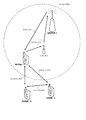
- FIG. 1 is a conceptual diagram of the wireless communication system of the present embodiment.
- the wireless communication system includes terminal apparatuses 1A to 1C, a repeater 2, and a base station apparatus 3.
- the terminal devices 1A to 1C are referred to as the terminal device 1.
- the repeater 2 has a function of amplifying the signal received from the terminal device 1 and transmitting the amplified signal.
- the serving cell 4 indicates an area covered by the base station device 3 (LTE).
- the uplink 5 is a link from the terminal device 1 to the base station device 3.
- a signal may be directly transmitted from the terminal device 1 to the base station device 3 without using a repeater.
- the downlink 7 is a link from the base station device 3 to the terminal device 1.
- the uplink 5 and the downlink 7 are also referred to as a cellular link or a cellular communication path. Communication between the terminal device 1 and the base station device 3 is also referred to as cellular communication.
- the D2D link 9 is a link between the terminal devices 1.
- the D2D link 9 is also referred to as a D2D communication path, a ProSe link, or a ProSe communication path.
- D2D discovery is a process / procedure that specifies that a terminal device 1 is in proximity to another terminal device 1 using EUTRA (in proximity).
- the D2D communication is communication between the two adjacent terminal apparatuses 1 using an EUTRAN communication path established between the two terminal apparatuses 1. For example, the communication path may be established directly between the terminal devices 1.
- the D2D link 9 may include a ProSe-assisted WLAN (Wireless Local Area Network) direct communication path.
- a ProSe-assisted WLAN direct communication path may be established.
- two terminal devices 1 that are close to each other are discovered based on D2D discovery using EUTRAN, and an EUTRAN communication path or a ProSe-assisted WLAN (WirelessWireLocal Area) between the two discovered terminal devices 1.
- Network a direct communication path may be established.
- the downlink physical channel and the downlink physical signal are collectively referred to as a downlink signal.
- the uplink physical channel and the uplink physical signal are collectively referred to as an uplink signal.
- the physical channel is used to transmit information output from an upper layer.
- Physical signals are not used to transmit information output from higher layers, but are used by the physical layer.
- uplink physical channels are used in uplink wireless communication.
- -PUCCH Physical Uplink Control Channel
- PUSCH Physical Uplink Shared Channel
- PRACH Physical Random Access Channel
- PUCCH is a physical channel used for transmitting uplink control information (Uplink Control Information: UCI).
- Uplink control information includes downlink channel state information (Channel State Information: CSI), scheduling request (Scheduling Request: SR) indicating PUSCH resource request, downlink data (Transport block, Downlink-Shared Channel, DL-SCH).
- ACK acknowledgenowledgement
- NACK negative-acknowledgement
- ACK / NACK is also referred to as HARQ-ACK or HARQ feedback.
- PUSCH is a physical channel used for transmitting uplink data (Uplink-Shared Channel: UL-SCH) and / or HARQ-ACK and / or channel state information.
- uplink data Uplink-Shared Channel: UL-SCH
- HARQ-ACK ACK-ACK
- PRACH is a physical channel used to transmit a random access preamble.
- the PRACH is used in an initial connection establishment (initial connection establishment) procedure, a handover procedure, and a connection reestablishment (connection re-establishment) procedure.
- uplink Physical signals are used in uplink wireless communication.
- UL RS Uplink Reference Signal
- DMRS Demodulation Reference Signal
- SRS Sounding Reference Signal
- DMRS is related to transmission of PUSCH or PUCCH.
- DMRS is time-multiplexed with PUSCH or PUCCH.
- the base station apparatus 3 uses DMRS to perform propagation channel correction for PUSCH or PUCCH. Transmitting both PUSCH and DMRS is simply referred to as transmitting PUSCH. Transmitting both PUCCH and DMRS is simply referred to as transmitting PUCCH.
- SRS is not related to PUSCH or PUCCH transmission.
- the base station apparatus 3 uses SRS to measure the uplink channel state.
- the following downlink physical channels are used in downlink wireless communication.
- PBCH Physical Broadcast Channel
- PCFICH Physical Control Format Indicator Channel
- PHICH Physical Hybrid automatic repeat request Indicator Channel
- PDCCH Physical Downlink Control Channel
- EPDCCH Enhanced Physical Downlink Control Channel
- PDSCH Physical Downlink Shared Channel
- PMCH Physical Multicast Channel
- the PBCH is used to broadcast a master information block (Master Information Block: MIB, Broadcast Channel: BCH) commonly used in the terminal device 1.
- MIBs are transmitted at 40 ms intervals, and MIBs are repeatedly transmitted at 10 ms intervals.
- the MIB includes information indicating SFN.
- SFN system frame number
- MIB is system information.
- PCFICH is used for transmitting information indicating a region (OFDM symbol) used for transmission of PDCCH.
- PHICH is used to transmit an HARQ indicator (HARQ feedback) indicating ACK (ACKnowledgement) or NACK (Negative ACKnowledgement) for uplink data (Uplink Shared Channel: UL-SCH) received by the base station apparatus 3.
- HARQ feedback indicating ACK (ACKnowledgement) or NACK (Negative ACKnowledgement) for uplink data (Uplink Shared Channel: UL-SCH) received by the base station apparatus 3.
- the PDCCH and EPDCCH are used to transmit downlink control information (Downlink Control Information: DCI).
- DCI Downlink Control Information
- the downlink control information is also referred to as a DCI format.
- the downlink control information includes a downlink grant (downlink grant) and an uplink grant (uplink grant).
- the downlink grant is also referred to as downlink assignment (downlink allocation) or downlink assignment (downlink allocation).
- the uplink grant is used for scheduling a single PUSCH within a single cell.
- the uplink grant is used for scheduling a single PUSCH in a certain subframe.
- the downlink grant is used for scheduling a single PDSCH within a single cell.
- the downlink grant is used for scheduling the PDSCH in the same subframe as the subframe in which the downlink grant is transmitted.
- CRC Cyclic Redundancy Check
- CRC parity bits are scrambled by C-RNTI (Cell-Radio Network Temporary Identifier) or SPS C-RNTI (Semi-Persistent Scheduling Cell-Radio Network Temporary Identifier).
- C-RNTI and SPS C-RNTI are identifiers for identifying the terminal device 1 in the cell.
- the C-RNTI is used to control PDSCH resources or PUSCH resources in a single subframe.
- the SPS C-RNTI is used to periodically allocate PDSCH or PUSCH resources.
- PDSCH is used to transmit downlink data (Downlink Shared Channel: DL-SCH).
- PMCH is used to transmit multicast data (Multicast Channel: MCH).
- the synchronization signal is used for the terminal device 1 to synchronize the downlink frequency domain and time domain.
- the synchronization signal is arranged in subframes 0 and 5 in the radio frame.
- the downlink reference signal is used for the terminal device 1 to correct the propagation path of the downlink physical channel.
- the downlink reference signal is used for the terminal device 1 to calculate downlink channel state information.
- the downlink reference signal is used for the terminal device 1 to measure the geographical position of the own device.
- downlink reference signals the following five types are used.
- -CRS Cell-specific Reference Signal
- URS UE-specific Reference Signal
- PDSCH PDSCH
- DMRS Demodulation Reference Signal
- EPDCCH Non-Zero Power Chanel State Information-Reference Signal
- ZP CSI-RS Zero Power Chanel State Information-Reference Signal
- MBSFN RS Multimedia Broadcast and Multicast Service over Single Frequency Network Reference signal
- CRS is transmitted in the entire bandwidth of the subframe.
- CRS is used to demodulate PBCH / PDCCH / PHICH / PCFICH / PDSCH.
- the CRS may be used for the terminal device 1 to calculate downlink channel state information.
- PBCH / PDCCH / PHICH / PCFICH is transmitted through an antenna port used for CRS transmission.
- URS related to PDSCH is transmitted in a subframe and a band used for transmission of PDSCH related to URS.
- URS is used to demodulate the PDSCH with which the URS is associated.
- the PDSCH is transmitted through an antenna port used for CRS transmission or an antenna port used for URS transmission.
- DMRS related to EPDCCH is transmitted in subframes and bands used for transmission of EPDCCH related to DMRS.
- DMRS is used to demodulate the EPDCCH with which DMRS is associated.
- the EPDCCH is transmitted through an antenna port used for DMRS transmission.
- NZP CSI-RS is transmitted in the set subframe.
- the resource for transmitting the NZP CSI-RS is set by the base station apparatus 3.
- the NZP CSI-RS is used by the terminal device 1 to calculate downlink channel state information.
- the terminal device 1 performs signal measurement (channel measurement) using NZP CSI-RS.
- ZP CSI-RS resources are set by the base station device 3.
- the base station apparatus 3 transmits ZP CSI-RS with zero output. That is, the base station apparatus 3 does not transmit ZP CSI-RS.
- the base station apparatus 3 does not transmit PDSCH and EPDCCH in the resource set by ZP CSI-RS.
- the terminal device 1 can measure interference in a resource supported by NZP CSI-RS in a certain cell.
- the MBSFN RS is transmitted in the entire band of the subframe used for PMCH transmission.
- the MBSFN RS is used for PMCH demodulation.
- PMCH is transmitted through an antenna port used for transmission of MBSFN RS.
- a downlink signal, an uplink signal, or a signal newly defined for D2D is used. Also good. Signals (physical channels and physical signals) transmitted and received in the D2D link 9 are also referred to as signals used for D2D, signals for D2D, and D2D signals.
- BCH, MCH, UL-SCH and DL-SCH are transport channels.
- a channel used in a medium access control (Medium Access Control: MAC) layer is referred to as a transport channel.
- a unit of data in a transport channel used in the MAC layer is also referred to as a transport block (transport block: TB) or a MAC PDU (Protocol Data Unit).
- transport block transport block: TB
- MAC PDU Network Data Unit
- HARQ HybridbrAutomatic Repeat reQuest
- the transport block is a unit of data that the MAC layer delivers to the physical layer. In the physical layer, the transport block is mapped to a code word, and an encoding process is performed for each code word.
- LTE supports two radio frame structures.
- the two radio frame structures are frame structure type 1 and frame structure type 2.
- Frame structure type 1 is applicable to FDD.
- Frame structure type 2 is applicable to TDD.
- FIG. 2 is a diagram illustrating a schematic configuration of a radio frame according to the present embodiment.
- the horizontal axis is a time axis.
- Each of the type 1 and type 2 radio frames is 10 ms long and is defined by 10 subframes.
- Each subframe is 1 ms long and is defined by two consecutive slots.
- Each of the slots is 0.5 ms long.
- the i-th subframe in the radio frame is composed of a (2 ⁇ i) th slot and a (2 ⁇ i + 1) th slot.
- the downlink subframe is a subframe reserved for downlink transmission.
- the uplink subframe is a subframe reserved for uplink transmission.
- the special subframe is composed of three fields. The three fields are DwPTS (Downlink Pilot Time Slot), GP (Guard Period), and UpPTS (Uplink Pilot Time Slot). The total length of DwPTS, GP, and UpPTS is 1 ms.
- DwPTS is a field reserved for downlink transmission.
- UpPTS is a field reserved for uplink transmission.
- GP is a field in which downlink transmission and uplink transmission are not performed. Note that the special subframe may be composed of only DwPTS and GP, or may be composed of only GP and UpPTS.
- the frame structure type 2 radio frame is composed of at least a downlink subframe, an uplink subframe, and a special subframe.
- FIG. 3 is a diagram showing the configuration of the slot according to the present embodiment.
- normal CP Cyclic Prefix
- SC-FDMA symbol The physical signal or physical channel transmitted in each of the slots is represented by a resource grid.
- the horizontal axis is a time axis
- the vertical axis is a frequency axis.
- the resource grid is defined by a plurality of subcarriers and a plurality of OFDM symbols.
- the resource grid is defined by a plurality of subcarriers and a plurality of SC-FDMA symbols.
- a resource grid may be defined by multiple subcarriers and multiple SC-FDMA symbols.
- the number of subcarriers constituting one slot depends on the cell bandwidth.
- the number of OFDM symbols or SC-FDMA symbols constituting one slot is seven.
- Each element in the resource grid is referred to as a resource element.
- the resource element is identified using a subcarrier number and an OFDM symbol or SC-FDMA symbol number.
- the resource block is used to express mapping of a certain physical channel (such as PDSCH or PUSCH) to a resource element.
- resource blocks virtual resource blocks and physical resource blocks are defined.
- a physical channel is first mapped to a virtual resource block. Thereafter, the virtual resource block is mapped to the physical resource block.
- One physical resource block is defined by 7 consecutive OFDM symbols or SC-FDMA symbols in the time domain and 12 consecutive subcarriers in the frequency domain. Therefore, one physical resource block is composed of (7 ⁇ 12) resource elements.
- One physical resource block corresponds to one slot in the time domain and corresponds to 180 kHz in the frequency domain. Physical resource blocks are numbered from 0 in the frequency domain.
- extended CP may be applied to OFDM symbols or SC-FDMA symbols.
- the number of OFDM symbols or SC-FDMA symbols constituting one slot is seven.
- FIG. 4 is a diagram showing the D2D resource of the present embodiment.
- the horizontal axis is a time axis
- the vertical axis is a frequency axis.
- D indicates a downlink subframe
- S indicates a special subframe
- U indicates an uplink subframe.
- One FDD cell corresponds to one downlink carrier or one downlink carrier and one uplink carrier.
- One TDD cell corresponds to one TDD carrier.
- One D2D cell corresponds to one D2D carrier.
- the downlink signal used for the cellular communication is arranged in the subframe of the downlink carrier, and the uplink signal used for the cellular communication is arranged in the subframe of the uplink carrier.
- the D2D signal to be used is arranged in a subframe of the uplink carrier.
- a carrier corresponding to a cell in the downlink is referred to as a downlink component carrier.
- a carrier corresponding to a cell in the uplink is referred to as an uplink component carrier.
- downlink signals used for cellular communication are arranged in downlink subframes and DwPTS
- uplink signals used for cellular communication are arranged in uplink subframes and UpPTS
- D2D The D2D signal to be used is arranged in the uplink subframe and the UpPTS.
- the D2D cell is a cell dedicated to D2D, and a D2D signal used for D2D is arranged. That is, the D2D carrier to which the D2D cell corresponds is a carrier dedicated to D2D.
- the D2D carrier is also referred to as a D2D dedicated frequency band (dedicated spectrum) or a PS frequency band (Public Safety).
- the D2D resource in the D2D cell is also referred to as a D2D resource in the D2D dedicated frequency band or a PS resource. In 3GPP, it is considered that the D2D dedicated frequency band is used for PS. Note that PS resources may be used for purposes other than PS.
- the D2D cell used for PS may not be a serving cell.
- the terminal device 1 may establish a D2D link for PS in the D2D dedicated frequency band without establishing a cellular link.
- the terminal device 1 When establishing a D2D link for PS in the D2D dedicated frequency band without establishing a cellular link, the terminal device 1 establishes a cellular link in advance, performs settings related to D2D for PS, and Authentication for D2D may be performed.
- the base station apparatus 3 controls D2D resources reserved for D2D.
- the base station apparatus 3 reserves a part of the uplink carrier resources of the FDD cell as D2D resources.
- the base station apparatus 3 reserves part of the uplink subframe of the TDD cell and the UpPTS resource as the D2D resource.
- the base station apparatus 3 reserves all or some of the resources of the D2D cell as D2D resources.
- the base station apparatus 3 transmits to the terminal apparatus 1 an upper layer signal including information indicating the D2D resource reserved in each cell.
- the terminal device 1 sets a parameter D2D-ResourceConfig indicating the D2D resource reserved in each of the cells based on the upper layer signal received from the base station device 3. That is, the base station apparatus 3 sets the parameter D2D-ResourceConfig indicating the D2D resource reserved in each cell to the terminal apparatus 1 via the upper layer signal.
- a part of the frequency band of the uplink carrier corresponding to the FDD cell may be reserved as a D2D dedicated frequency band. Further, a part of the frequency band of the uplink subframe corresponding to the TDD cell may be reserved as a D2D dedicated frequency band.
- the base station apparatus 3 may notify the terminal apparatus 1 whether or not each of the D2D resource sets is a PS resource. Note that the terminal device 1 does not simultaneously perform D2D transmission processing and D2D reception processing in one carrier.
- D2D discovery / communication in D2D resources used for purposes other than PS is controlled or monitored by the base station apparatus 3.
- the base station device 3 controls the uplink and downlink CP lengths. Note that the base station apparatus 3 may individually control the uplink and downlink CP lengths for each serving cell.
- Terminal apparatus 1 detects the CP length of the downlink signal for the serving cell, excluding PMCH and MBSFN RS, based on the PBCH for the serving cell. Extended CP is always applied to PMCH and MBSFN RS.
- the base station apparatus 3 transmits an upper layer signal including information indicating the CP length of the uplink signal in the serving cell to the terminal apparatus 1.
- the terminal device 1 sets a parameter UL-CyclicPrefixLength indicating the uplink CP length in the serving cell based on the upper layer signal received from the base station device 3. That is, the base station apparatus 3 sets the parameter UL-CyclicPrefixLength indicating the uplink CP length in the serving cell to the terminal apparatus 1 via the higher layer signal.
- the extended CP may be applied in the uplink in consideration of the processing delay in the repeater 2.
- a D2D communication path from a certain terminal device 1 to another terminal apparatus 1 and a D2D communication path from the other terminal apparatus 1 to the certain terminal apparatus 1 are the same. Therefore, the CP length used for transmission from a certain terminal device 1 to another terminal device 1 and the CP length used for transmission from the other terminal device 1 to the certain terminal device 1 in D2D are: Preferably they are the same.
- the CP length in the D2D link may be a normal CP. That is, the CP length in the D2D link is defined in advance according to the specification or the like and may be fixed.
- the CP length in the D2D link may be an extended CP.
- the radio conditions between the terminal devices 1, the geographical distance between the terminal devices 1, and / or the uplink transmission timing for cellular communication in each of the terminal devices 1, etc. 1 or the base station apparatus 3 may control the CP length in the D2D link. That is, the CP length for D2D, the CP length for the downlink, and the CP length for the uplink may be individually controlled. That is, the CP length for each of the D2D signal and the uplink signal transmitted on the same carrier may be individually set.
- the base station apparatus 3 may transmit an upper layer signal including information indicating the CP length for D2D to the terminal apparatus 1.
- the terminal device 1 may set the parameter D2D-CyclicPrefixLength indicating the CP length for D2D based on the upper layer signal received from the base station device 3. That is, the base station apparatus 3 may set the parameter D2D-CyclicPrefixLength indicating the CP length for D2D in the terminal apparatus 1 via the higher layer signal.
- the terminal device 1 may determine the CP length for the D2D based on the D2D signal and / or information received from the other terminal device 1.
- the terminal device 1 may transmit information indicating the CP length for D2D to other terminal devices 1.
- the other terminal device may determine the CP length for D2D based on the information indicating the CP length for D2D received from the terminal device 1.
- the base station apparatus 3 may transmit an upper layer signal including information indicating the CP length for D2D discovery to the terminal apparatus 1.
- the base station apparatus 3 may transmit an upper layer signal including information indicating the CP length for D2D communication to the terminal apparatus 1.
- CP length for D2D discovery and / or D2D communication may be zero.
- TAG Timing Advance Group
- TA Timing Advance
- PTAG Primary Timing Advance Group
- the timing reference cell for PTAG is a primary cell.
- STAG Secondary Timing Advance Group
- the STAG includes at least one serving cell with a configured uplink.
- the timing reference cell for STAG is any one secondary cell included in STAG.
- D2D cell may not belong to any TAG.
- the base station device 3 transmits a TA (Timing Advance) command for PTAG and a TA command for STAG to the terminal device 1.
- the TA command is transmitted together with a TAG ID (identity) indicating the TAG to which the TA command corresponds.
- the TAG ID for PTAG is 0.
- the TAG ID for the STAG is set by the base station device 3 and is one of 1 to 3.
- the terminal device 1 adjusts the uplink transmission timing for the PUSCH / PUCCH / SRS of the primary cell based on the received TA command.
- the uplink transmission timing for the PUSCH / PUCCH / SRS of the secondary cell is the same as the uplink transmission timing of the primary cell.
- the terminal device 1 adjusts the uplink transmission timing for the PUSCH / PUCCH / SRS of all the secondary cells in the STAG based on the received TA command.
- the uplink transmission timing for PUSCH / PUCCH / SRS is the same for all secondary cells in the STAG.
- the terminal device 1 measures the reference timing based on the downlink signal (for example, synchronization signal) of the timing reference cell.
- the terminal device 1 determines a TA value for uplink transmission based on the TA command.
- the terminal device 1 determines the uplink transmission timing based on the measured reference timing and the TA value.
- FIG. 5 is a diagram showing the transmission timing of the terminal device 1 in the present embodiment.
- the horizontal axis is a time axis.
- the downlink transmission timing is the downlink signal transmission timing by the base station apparatus 3
- the downlink reception timing is the downlink signal reception timing by the terminal apparatus 1
- the uplink transmission timing is by the terminal apparatus 1.
- the uplink reception timing is the reception timing of the uplink signal by the base station device 3
- the D2D transmission timing is the transmission timing of the D2D signal by the terminal device 1.
- the base station apparatus 3 preferably controls the TA value for the uplink transmission so that the downlink transmission timing and the uplink transmission timing match.
- the D2D signal in a certain subframe is an uplink signal in an adjacent subframe. It becomes interference to. Therefore, on the terminal device 1 side, the D2D transmission timing is preferably the same as the uplink transmission timing. Accordingly, in FIG. 5, the D2D signal transmitted in subframe # 4 causes interference only to subframe # 4 on the base station apparatus 3 side, and does not interfere with adjacent subframe # 3/5.
- the D2D transmission timing of the terminal device 1 in the D2D dedicated frequency band may be different from the uplink transmission timing.
- the D2D transmission timing in the D2D dedicated frequency band may be determined based on a global navigation satellite system (Global Navigation Satellite System: GNSS) and / or a D2D signal received from another terminal device 1.
- GNSS Global Navigation Satellite System
- the uplink signal transmission and the D2D signal transmission occur in the same subframe (timing, symbol) of the same cell, the uplink transmission timing and the D2D transmission timing are the same, and the CP length of the uplink signal and the When the CP length of the D2D signal is the same, the terminal device 1 may transmit the uplink signal and the D2D signal simultaneously in the same subframe (timing) of the same cell.
- the terminal device 1 When transmission of an uplink signal and transmission of a D2D signal occur in the same subframe (timing, symbol) of the same cell, and the uplink transmission timing and the D2D transmission timing are different, the terminal device 1 transmits the uplink signal or Any one of the transmissions of the D2D signal may be dropped.
- the terminal apparatus 1 Either uplink signal transmission or D2D signal transmission may be dropped.
- the terminal apparatus 1 drops either the uplink signal transmission or the D2D signal transmission. May be.
- the terminal apparatus 1 uses the same subframe (timing) of the same cell for the uplink signal and the D2D signal. May be sent simultaneously.
- the terminal apparatus 1 transmits the uplink signal and the D2D signal to the same subframe (timing) of different cells. May be sent simultaneously.
- the terminal apparatus 1 drops either the uplink signal transmission or the D2D signal transmission. May be.
- the TA timer of this embodiment will be described.
- the terminal device 1 manages a TA timer for each TAG.
- the terminal device 1 starts or restarts the TA timer related to the TAG to which the TA command is applied.
- the terminal device 1 When the TA timer related to PTAG expires, the terminal device 1 performs the following processing (A1) to (A3) for the uplink.
- Process (A1) The HARQ buffer related to the uplink transmission process is flushed for all serving cells.
- the terminal device 1 When the TA timer related to STAG expires, the terminal device 1 performs the following processing (B1) and (B2) for the uplink.
- Process (B1) All HARQ buffers related to the uplink transmission process are flushed to all serving cells belonging to the STAG.
- the terminal device 1 When the TA timer related to the TAG to which the serving cell belongs is not running, the terminal device 1 does not perform uplink transmission in the serving cell except for random access preamble transmission. When the TA timer related to the PTAG is not running, the terminal device 1 does not perform uplink transmission in all the serving cells except for transmission of a random access preamble in the primary cell.
- the terminal device 1 when the TA timer related to the PTAG expires, the terminal device 1 performs the following processing (C1) to processing (C8) for all cells in which the D2D resources are set except for the D2D dedicated frequency band. Do some or all.
- the terminal device 1 performs a part of the following processes (C1) to (C8) or all of the cells belonging to the STAG except for the D2D dedicated frequency band. Do everything.
- WLAN communication other than ProSe-assisted WLAN direct communication may not be stopped / disconnected.
- the MAC layer may instruct the RRC layer to discard all settings for D2D in the RRC layer.
- the terminal device 1 When the TA timer related to the TAG to which the serving cell belongs is not running, the terminal device 1 does not perform D2D transmission in the serving cell except for D2D transmission in the D2D dedicated frequency band. When the TA timer related to PTAG is not running, the terminal device 1 does not perform D2D transmission in all serving cells except for D2D transmission in the D2D dedicated frequency band.
- the D2D transmission timing is the same as the D2D transmission timing in one terminal device 1 because of the same D2D transmission timing and uplink transmission timing.
- the D2D transmission timing in one terminal device 1 is different.
- the terminal device 1 includes information indicating the timing reference cell in the own device and information indicating the D2D transmission timing (TA value from the reference timing measured based on the downlink signal of the timing reference cell) in the own device. Alternatively, it may be transmitted to another terminal device 1.
- the D2D transmission timing may be controlled between the terminal devices 1.
- the terminal device 1 may determine a TA value for D2D based on the D2D signal received from the other terminal device 1 and transmit a TA command indicating the TA value to the other terminal device 1.
- a TA timer for D2D may be defined.
- the terminal device 1 may start or restart the TA timer when it receives a TA command for D2D.
- the terminal device 1 may perform part or all of the processes (C1) to (C8) for the D2D resource corresponding to the TA timer.
- the terminal device 1 activates or deactivates the D2D function.
- D2D activation and deactivation is preferably controlled by the MAC layer.
- the terminal device 1 may activate or deactivate D2D by an input from a user or an application.
- the terminal device 1 may activate or deactivate D2D based on the D2D command (information) received from the base station device 3.
- the D2D command is used to activate and deactivate D2D.
- the D2D command may be included in a MAC CE (Control Element) or RRC message.
- the D2D command may be included in the activation / deactivation MAC CE.
- the activation / deactivation MAC CE is used by the base station device 3 to activate and deactivate the secondary cell.
- the terminal device 1 may deactivate D2D when the D2D deactivation timer expires.
- the terminal device 1 may start or restart the D2D deactivation timer when D2D is activated based on an input from a user or an application. Further, the terminal device 1 may start or restart the D2D deactivation timer when D2D is activated based on the received D2D command.
- the base station apparatus 3 may set the length of the D2D deactivation timer in the terminal apparatus 1 via an upper layer signal. Note that the length of the D2D deactivation timer may be different for each cell. Further, the length of the D2D deactivation timer may be different for each set of D2D resources. Further, the length of the D2D deactivation timer may be different for each D2D communication path.
- the D2D deactivation timer may not be defined for the D2D dedicated frequency band. Further, the length of the D2D deactivation timer for the D2D dedicated frequency band may be fixed (for example, infinite). That is, the base station apparatus 3 may transmit, to the terminal apparatus 1, an upper layer signal including information indicating the length of the D2D deactivation timer for a set of cells or D2D resources, excluding the D2D dedicated frequency band. .
- the terminal device 1 may transmit information indicating that the D2D function is activated to the base station device 3.
- Information indicating that the D2D function has been activated may be included in the MAC CE or RRC message.
- the terminal device 1 may not report information indicating that the D2D function has been activated to the base station device 3. Note that the terminal apparatus 1 may transmit / report ACK (HARQ-ACK) to the transport block including the D2D command to the base station apparatus 3 using PUSCH or PUCCH.
- HARQ-ACK report ACK
- the terminal device 1 may transmit information indicating that the D2D function is deactivated to the base station device 3.
- Information indicating that the D2D function has been deactivated may be included in the MAC CE or RRC message.
- the terminal device 1 When the D2D function is deactivated based on the D2D command, the terminal device 1 does not have to report information indicating that the D2D function is deactivated to the base station device 3. Note that the terminal apparatus 1 may transmit / report ACK (HARQ-ACK) to the transport block including the D2D command to the base station apparatus 3 using PUSCH or PUCCH. When the D2D function is deactivated, the terminal device 1 may perform part or all of the processes (C1) to (C6).
- HARQ-ACK HARQ-ACK
- D2D function when the D2D function is deactivated, information indicating that the D2D function is deactivated may be transmitted to another terminal device 1 that performs D2D communication.
- Each of the D2D discovery function and the D2D communication function may be individually activated and deactivated.
- the terminal device 1 D2D discovery may be performed and initiated on the D2D link;
- D2) D2D communication may be performed and initiated on the D2D link;
- D3) ProSe-assisted WLAN direct communication may be performed or started on the D2D link;
- D4) In downlink, reception processing and monitoring of downlink signals related to the D2D link may be performed;
- D5) In uplink, transmission processing of an uplink signal related to the D2D link may be performed.
- the terminal device 1 When the D2D function is deactivated, the terminal device 1 (E1): Do not perform D2D discovery and do not initiate on D2D links; (E2): D2D communication is not performed and is not started in the D2D link; (E3): ProSe-assisted WLAN direct communication is not performed or started in the D2D link; (E4): In downlink, reception processing and monitoring of downlink signals related to the D2D link are not performed; (E5): In uplink, uplink signal transmission processing related to the D2D link is not performed.
- the downlink signal related to the D2D link is the information / DCI used to control the transmission power for the transmission of the D2D signal, the information indicating the start of the D2D discovery procedure / DCI, the D2D signal related to the D2D discovery Information indicating format / DCI, information used for generating D2D signal sequences related to D2D discovery / Information indicating D2D resources for DCI, D2D discovery or D2D communication / DCI, ProSe-assisted WLAN direct communication It includes information regarding settings, information indicating the settings of the D2D link, and the like.
- the uplink signal related to the D2D link includes information regarding the D2D link. Details of the information regarding the D2D link will be described later.
- D2D function may be activated and terminated for each cell, for each application, or for each D2D communication path.
- one D2D deactivation timer may be defined for each cell, each application, or each D2D communication path.
- the information / DCI for instructing the start of the D2D discovery procedure, the information / DCI used for generating the D2D signal sequence related to the D2D discovery, and the information / DCI indicating the D2D resource for the D2D discovery are: They may be transmitted together via a single PDCCH or a single EPDCCH.
- the terminal device 1 that has received the three pieces of information / DCI may perform the following processes (F1) to (F4).
- Process (F1) The D2D discovery procedure is started based on the information / DCI for instructing the start of the D2D discovery procedure.
- Process (F2) Generates a sequence of D2D signals related to D2D discovery based on the information / DCI used for the generation of sequences of D2D signals related to D2D discovery.
- Process (F4) The generated D2D signal is transmitted in the selected D2D resource.
- FIG. 6 is a diagram showing information related to D2D transmitted in the cellular link of the present embodiment.
- a cellular communication path is established between the base station apparatus 3 and the terminal apparatus 1A.
- a D2D communication path is established between the terminal device 1A and the terminal device 1B.
- the base station apparatus 3 may store information related to D2D. Performs transmission / reception processing.
- the terminal device 1A transmits information related to the D2D function to the base station device 3 (S600). Based on the received information related to the D2D function, the base station device 3 transmits information indicating the setting of the D2D link to the terminal device 1A (S602). The terminal device 1A establishes a D2D connection based on the received information indicating the setting of the D2D link (S604). The terminal device 1A transmits information related to the established D2D link (connection) to the base station device 3 (S606).
- the terminal apparatus 1A may transmit / transfer information indicating the setting of the D2D link to the terminal apparatus 1B.
- the terminal device 1B may have established a cellular communication channel with another base station device 3.
- the terminal device 1B may transmit information related to the D2D link to other base station devices 3.
- the plurality of base station devices 3 may transmit / receive / transfer information related to the D2D link via a backhaul established between the base station devices 3.
- the terminal device 1 ⁇ / b> B may have established a cellular communication path with the base station device 3.
- the terminal device 1B may transmit information related to the D2D link to the base station device 3.
- terminal devices 1 for example, one terminal device 1 in the group of terminal devices 1 performing D2D transmit information related to the D2D link to EUTRAN (base station device 3). Also good.
- the part of the terminal devices 1 may be determined among the terminal devices 1 performing the D2D.
- the base station apparatus 3 may instruct the partial terminal apparatus 1.
- the base station apparatus 3 may set whether to report information related to the D2D link to each of the terminal apparatuses 1 via an upper layer signal.
- the information related to the D2D function may include a part or all of the information (G1) to (G17). Each of information (G1) to information (G17) may be transmitted at different timings.
- G1 Information indicating whether the terminal device 1 has ProSe-assisted WLAN direct communication capability Information (G2): WLAN standard supported by the terminal device 1 (for example, IEEE (Institute of Electrical and Electronics) Engineers) 802.11a / b / g / n / ac, IEEE802.11 series) information / information (G3): ProSe-assisted WLAN that can be used for direct communication and supported by the terminal device 1 Information / information (G4) indicating the standard: Information / information indicating whether the terminal device 1 has the capability of D2D discovery in EUTRAN (G5): Information indicating whether the terminal device 1 has the capability of D2D communication in EUTRAN Information (G6): D2D discovery in EUTRAN by terminal device 1 / And information (G7) indicating whether or not the terminal device 1 has the ability to simultaneously perform cellular communication and ProSe-assisted WLAN direct communication.
- G2D discovery in EUTRAN for example, IEEE (Institute of Electrical and Electronics) Engineers) 802.11a
- Information (G8) Information / information (G9) indicating whether the terminal device 1 has the ability to simultaneously perform cellular communication and D2D discovery / communication in a single cell.
- Information / information (G10) indicating whether or not the transmission processing and the transmission processing of D2D discovery / communication are simultaneously performed: In the single FDD cell, the terminal device 1 receives cellular communication and D2D discovery / communication transmission processing.
- Information / information (G11) indicating whether or not the terminal device 1 has the ability to simultaneously perform Information / information (G12) indicating whether or not the reception processing of the cellular communication and the reception processing of the D2D communication / discovery are simultaneously performed: the terminal device 1 performs the cellular communication in a certain cell and the D2D communication / discovery in another cell Information / information (G13) indicating whether or not the terminal device 1 has the capability to simultaneously perform cellular communication transmission processing in a certain cell and D2D communication / discovery transmission processing in another cell Information / information (G14) indicating: Information / information (G15) indicating whether or not the terminal device 1 has the ability to simultaneously perform cellular communication reception processing in one cell and D2D communication / discovery reception processing in another cell.
- the base station apparatus 3 may transmit information indicating the D2D link setting to each terminal apparatus 1 for each set of D2D resources. Multiple sets of D2D resources may be set for one terminal device 1. One set of D2D resources may be included in one cell. Multiple sets of D2D resources may be set in one cell. One set of D2D resources may be set for each D2D communication path. In one terminal device 1, a plurality of D2D communication paths may be established.
- the information indicating the setting of the D2D link may include a part or all of the information (H1) to (H15). Each of information (H1) to information (H15) may be transmitted at different timings.
- H1 Information indicating the cell including the D2D resource Information
- H2D resource Information Information indicating the subframe including the D2D resource Information (H3): In the subframe, the frequency bandwidth of the D2D resource, and / Or information / information (H4) indicating frequency position: information / information (H5) indicating a virtual resource block or a physical resource block constituting a D2D resource in a subframe: information indicating a cell including a PS resource Information
- H6 Information / information (H7) indicating a subframe including a PS resource: Information / information (H8) indicating a frequency bandwidth and / or a frequency position of the PS resource in the subframe: Subframe Within the virtual resource block or physical resource block constituting the PS resource Information / information (H9): Information / information (H10) indicating validity / instruction of resource hopping of D2D signal (for example, PUSCH): Information / information (H11): D2D resource indicating hopping mode of resource of D2D signal Information / information (H
- H2 may indicate a period and an offset for the number of the subframe in which the D2D resource is reserved.
- the information (H2) may be expressed by a bitmap. Each bit of the bitmap may correspond to one subframe.
- the D2D signal hopping mode includes an inter-subframe mode and an intra / inter-subframe mode.
- inter-subframe mode D2D signal resources are hopped for each subframe.
- intra-subframe / inter-frame mode the resource of the D2D signal is hopped for each slot.
- the information regarding the D2D link may include a part or all of the information (I1) to (I42). Each of information (I1) to information (I42) may be transmitted at different timings.
- the terminal device 1 sends information related to the D2D link to the base station device 3 for each of the D2D resource sets, each of the D2D communication channels, each of the ProSe-assisted WLAN direct communication channels, and / or each of the applications. You may send it.
- the reporting of information regarding the D2D link may be triggered when any of the information (I1) to (I42) is changed. Moreover, the report of the information regarding the D2D link may be triggered when any value of the information (I1) to (I42) is changed by a threshold value or more. Also, reporting of information related to the D2D link may be triggered when any of the values (I1) to (I42) when the information related to the D2D link was last reported differs from the current value by more than a threshold value. Good. In this case, only the information corresponding to the trigger may be reported among the information (I1) to (I42). The report of information regarding the D2D link may be triggered based on an instruction from the base station device 3.
- reporting of information on the D2D link may be triggered.
- the QoS in the D2D communication path and / or the ProSe-assisted WLAN direct communication path does not satisfy the QoS corresponding to the QCI (QoS Class) Identifier) for the D2D communication path and / or the ProSe-assisted WLAN direct communication path.
- Reporting information on the D2D link may be triggered.
- the terminal apparatus 1 is triggered to report at least one information related to the D2D link, is assigned a PUSCH for initial transmission in the uplink, and is assigned to the PUSCH as a result of a logical channel prioritization procedure.
- the information regarding the D2D link may be reported using the PUSCH.
- QCI is defined by packet priority, allowable packet delay time (packet delay budget), allowable packet loss rate (packet error loss rate), transmission rate (bit rate) guaranteed or not.
- QCI is a scalar that can be used as a control for specific packet forwarding operations.
- the base station device 3 may transmit information indicating the QCI corresponding to the D2D communication path to the terminal device 1.
- the geographical position of the terminal device 1 may be measured based on PRS and / or Global Navigation Satellite System (Global GNSS).
- Global GNSS Global Navigation Satellite System
- the terminal apparatus 1 determines a subset of D2D resources used for transmission / reception of D2D signals from the D2D resources indicated by the information indicating the D2D link setting, and indicates the determined subset of D2D resources Information (I1) may be transmitted to the base station apparatus 3.
- FIG. 7 is a schematic block diagram showing the configuration of the terminal device 1 of the present embodiment.
- the terminal device 1 includes an upper layer processing unit 101, a control unit 103, a receiving unit 105, a transmitting unit 107, and a transmission / reception antenna unit 109.
- the upper layer processing unit 101 includes a radio resource control unit 1011, a scheduling information interpretation unit 1013, and a D2D control unit 1015.
- the reception unit 105 includes a decoding unit 1051, a demodulation unit 1053, a demultiplexing unit 1055, a radio reception unit 1057, and a channel measurement unit 1059.
- the transmission unit 107 includes an encoding unit 1071, a modulation unit 1073, a multiplexing unit 1075, a radio transmission unit 1077, and an uplink reference signal generation unit 1079.
- the upper layer processing unit 101 outputs uplink data (transport block) generated by a user operation or the like to the transmission unit 107.
- the upper layer processing unit 101 includes a medium access control (MAC: Medium Access Control) layer, a packet data integration protocol (Packet Data Convergence Protocol: PDCP) layer, a radio link control (Radio Link Control: RLC) layer, and radio resource control. Process the (Radio Resource Control: RRC) layer.
- MAC Medium Access Control
- PDCP Packet Data Convergence Protocol
- RLC Radio Link Control
- RRC Radio Resource Control
- the radio resource control unit 1011 included in the upper layer processing unit 101 manages various setting information / parameters of the own device.
- the radio resource control unit 1011 sets various setting information / parameters based on the upper layer signal received from the base station apparatus 3. That is, the radio resource control unit 1011 sets various setting information / parameters based on information indicating various setting information / parameters received from the base station apparatus 3. Also, the radio resource control unit 1011 generates information arranged in each uplink channel and outputs the information to the transmission unit 107.
- the scheduling information interpretation unit 1013 provided in the upper layer processing unit 101 interprets the DCI format (scheduling information) received via the reception unit 105, and based on the interpretation result of the DCI format, the reception unit 105 and the transmission unit Control information is generated in order to perform the control of 107 and output to the control unit 103.
- the D2D control unit 1015 included in the upper layer processing unit 101 controls D2D discovery, D2D communication, and / or ProSe-assisted WLAN direct communication based on various setting information / parameters managed by the radio resource control unit 1011. I do.
- the D2D control unit 1015 may generate information related to D2D to be transmitted to another terminal device 1 or EUTRAN (base station device 3).
- the control unit 103 generates a control signal for controlling the receiving unit 105 and the transmitting unit 107 based on the control information from the higher layer processing unit 101. Control unit 103 outputs the generated control signal to receiving unit 105 and transmitting unit 107 to control receiving unit 105 and transmitting unit 107.
- the receiving unit 105 separates, demodulates, and decodes the received signal received from the base station apparatus 3 via the transmission / reception antenna unit 109 according to the control signal input from the control unit 103, and the decoded information is the upper layer processing unit 101. Output to.
- the radio reception unit 1057 converts a downlink signal received via the transmission / reception antenna unit 109 into a baseband signal by orthogonal demodulation (down-conversion: down covert), removes unnecessary frequency components, and has an appropriate signal level.
- the amplification level is controlled so as to be maintained at, and quadrature demodulation is performed based on the in-phase component and the quadrature component of the received signal, and the quadrature demodulated analog signal is converted into a digital signal.
- the radio reception unit 1057 removes a portion corresponding to CP (Cyclic Prefix) from the converted digital signal, and performs a fast Fourier transform (FFT) on the signal from which the CP has been removed to obtain a frequency domain signal. Extract.
- CP Cyclic Prefix
- the demultiplexing unit 1055 separates the extracted signals into PHICH, PDCCH, EPDCCH, PDSCH, and downlink reference signals. Further, demultiplexing section 1055 compensates the propagation path of PHICH, PDCCH, EPDCCH, and PDSCH from the estimated propagation path value input from channel measurement section 1059. Also, the demultiplexing unit 1055 outputs the demultiplexed downlink reference signal to the channel measurement unit 1059.
- the demodulating unit 1053 multiplies the PHICH by a corresponding code and synthesizes the signal, demodulates the synthesized signal using a BPSK (Binary Phase Shift Shift Keying) modulation method, and outputs the demodulated signal to the decoding unit 1051.
- Decoding section 1051 decodes the PHICH addressed to the own apparatus, and outputs the decoded HARQ indicator to higher layer processing section 101.
- Demodulation section 1053 performs QPSK modulation demodulation on PDCCH and / or EPDCCH, and outputs the result to decoding section 1051.
- Decoding section 1051 attempts to decode PDCCH and / or EPDCCH, and outputs the decoded downlink control information and the RNTI corresponding to the downlink control information to higher layer processing section 101 when the decoding is successful.
- the demodulation unit 1053 demodulates the modulation scheme notified by the downlink grant such as QPSK (Quadrature Shift Keying), 16QAM (Quadrature Amplitude Modulation), 64QAM, and the like to the decoding unit 1051.
- the decoding unit 1051 performs decoding based on the information regarding the coding rate notified by the downlink control information, and outputs the decoded downlink data (transport block) to the higher layer processing unit 101.
- the channel measurement unit 1059 measures the downlink path loss and channel state from the downlink reference signal input from the demultiplexing unit 1055, and outputs the measured path loss and channel state to the upper layer processing unit 101. Also, channel measurement section 1059 calculates an estimated value of the downlink propagation path from the downlink reference signal, and outputs it to demultiplexing section 1055. The channel measurement unit 1059 performs channel measurement and / or interference measurement in order to calculate CQI.
- the transmission unit 107 generates an uplink reference signal according to the control signal input from the control unit 103, encodes and modulates the uplink data (transport block) input from the higher layer processing unit 101, PUCCH, The PUSCH and the generated uplink reference signal are multiplexed and transmitted to the base station apparatus 3 via the transmission / reception antenna unit 109.
- the encoding unit 1071 performs encoding such as convolutional encoding and block encoding on the uplink control information input from the higher layer processing unit 101.
- the encoding unit 1071 performs turbo encoding based on information used for PUSCH scheduling.
- the modulation unit 1073 modulates the coded bits input from the coding unit 1071 using a modulation method notified by downlink control information such as BPSK, QPSK, 16QAM, 64QAM, or a modulation method predetermined for each channel. .
- Modulation section 1073 determines the number of spatially multiplexed data sequences based on information used for PUSCH scheduling, and transmits the same PUSCH by using MIMO (Multiple Input Multiple Multiple Output) SM (Spatial Multiplexing).
- MIMO Multiple Input Multiple Multiple Output
- SM Spatial Multiplexing
- the uplink reference signal generation unit 1079 is a physical layer cell identifier (physical layer cell identity: PCI, Cell ID, etc.) for identifying the base station apparatus 3, a bandwidth for arranging the uplink reference signal, and an uplink grant.
- a sequence determined by a predetermined rule (formula) is generated on the basis of the cyclic shift and the parameter value for generating the DMRS sequence notified in (1).
- the multiplexing unit 1075 rearranges the PUSCH modulation symbols in parallel according to the control signal input from the control unit 103, and then performs a discrete Fourier transform (Discrete-Fourier-Transform: DFT). Also, multiplexing section 1075 multiplexes the PUCCH and PUSCH signals and the generated uplink reference signal for each transmission antenna port. That is, multiplexing section 1075 arranges the PUCCH and PUSCH signals and the generated uplink reference signal in the resource element for each transmission antenna port.
- DFT discrete Fourier transform
- Radio transmission section 1077 performs inverse fast Fourier transform (Inverse Fast Fourier Transform: IFFT) on the multiplexed signal to generate an SC-FDMA symbol, adds a CP to the generated SC-FDMA symbol, and A digital signal is generated, the baseband digital signal is converted into an analog signal, an excess frequency component is removed using a low-pass filter, the signal is up-converted to a carrier frequency, and power is amplified. Output to and send.
- IFFT inverse fast Fourier transform
- FIG. 8 is a schematic block diagram showing the configuration of the base station apparatus 3 of the present embodiment.
- the base station apparatus 3 includes an upper layer processing unit 301, a control unit 303, a reception unit 305, a transmission unit 307, and a transmission / reception antenna unit 309.
- the higher layer processing unit 301 includes a radio resource control unit 3011, a scheduling unit 3013, and a D2D control unit 3015.
- the reception unit 305 includes a decoding unit 3051, a demodulation unit 3053, a demultiplexing unit 3055, a wireless reception unit 3057, and a channel measurement unit 3059.
- the transmission unit 307 includes an encoding unit 3071, a modulation unit 3073, a multiplexing unit 3075, a radio transmission unit 3077, and a downlink reference signal generation unit 3079.
- the upper layer processing unit 301 includes a medium access control (MAC: Medium Access Control) layer, a packet data integration protocol (Packet Data Convergence Protocol: PDCP) layer, a radio link control (Radio Link Control: RLC) layer, a radio resource control (Radio). Resource (Control: RRC) layer processing. Further, upper layer processing section 301 generates control information for controlling receiving section 305 and transmitting section 307 and outputs the control information to control section 303.
- MAC Medium Access Control
- PDCP Packet Data Convergence Protocol
- RLC Radio Link Control
- Radio Radio Resource
- the radio resource control unit 3011 included in the higher layer processing unit 301 generates downlink data (transport block), system information, RRC message, MAC CE (Control Element), etc. arranged in the downlink PDSCH, or higher level. Obtained from the node and output to the transmission unit 307.
- the radio resource control unit 3011 manages various setting information / parameters of each terminal device 1.
- the radio resource control unit 1011 may set various setting information / parameters for each terminal apparatus 1 via higher layer signals. That is, the radio resource control unit 1011 transmits / broadcasts information indicating various setting information / parameters.
- the scheduling unit 3013 included in the upper layer processing unit 301 uses the received channel state information and the channel allocation information, the channel estimation value, the channel quality, and the like to assign the physical channel (PDSCH and PUSCH).
- the coding rate and modulation scheme and transmission power of the frame and physical channels (PDSCH and PUSCH) are determined.
- the scheduling unit 3013 Based on the scheduling result, the scheduling unit 3013 generates control information (for example, DCI format) for controlling the reception unit 305 and the transmission unit 307 and outputs the control information to the control unit 303.
- the scheduling unit 3013 further determines timing for performing transmission processing and reception processing.
- the D2D control unit 3015 included in the upper layer processing unit 301 performs D2D discovery and D2D communication in the terminal device 1 that performs communication using a cellular link based on various setting information / parameters managed by the radio resource control unit 3011. And / or control of ProSe-assisted WLAN direct communication.
- the D2D control unit 3015 may generate information related to D2D to be transmitted to another base station device 3 or the terminal device 1.
- the control unit 303 generates a control signal for controlling the reception unit 305 and the transmission unit 307 based on the control information from the higher layer processing unit 301.
- the control unit 303 outputs the generated control signal to the reception unit 305 and the transmission unit 307 and controls the reception unit 305 and the transmission unit 307.
- the receiving unit 305 separates, demodulates, and decodes the received signal received from the terminal device 1 via the transmission / reception antenna unit 309 according to the control signal input from the control unit 303, and outputs the decoded information to the higher layer processing unit 301.
- the radio reception unit 3057 converts the uplink signal received via the transmission / reception antenna unit 309 into a baseband signal by orthogonal demodulation (down-conversion: down covert), removes unnecessary frequency components, and has a signal level of The amplification level is controlled so as to be appropriately maintained, and quadrature demodulation is performed based on the in-phase component and the quadrature component of the received signal, and the analog signal subjected to the quadrature demodulation is converted into a digital signal.
- the wireless receiving unit 3057 removes a portion corresponding to CP (Cyclic Prefix) from the converted digital signal.
- the radio reception unit 3057 performs fast Fourier transform (FFT) on the signal from which the CP is removed, extracts a frequency domain signal, and outputs the signal to the demultiplexing unit 3055.
- FFT fast Fourier transform
- the demultiplexing unit 1055 demultiplexes the signal input from the radio receiving unit 3057 into signals such as PUCCH, PUSCH, and uplink reference signal. Note that this separation is performed based on radio resource allocation information included in the uplink grant that is determined in advance by the radio resource control unit 3011 by the base station device 3 and notified to each terminal device 1. In addition, demultiplexing section 3055 compensates for the propagation paths of PUCCH and PUSCH from the propagation path estimation value input from channel measurement section 3059. Further, the demultiplexing unit 3055 outputs the separated uplink reference signal to the channel measurement unit 3059.
- the demodulator 3053 performs inverse discrete Fourier transform (Inverse Discrete Fourier Transform: IDFT) on the PUSCH, acquires modulation symbols, and performs BPSK (Binary Shift Keying), QPSK, 16QAM,
- IDFT inverse discrete Fourier transform
- BPSK Binary Shift Keying
- QPSK Quadrature Phase Keying
- 16QAM 16QAM
- the received signal is demodulated using a predetermined modulation scheme such as 64QAM, or the modulation method notified by the own device to each terminal device 1 in advance using an uplink grant.
- the demodulator 3053 uses the MIMO SM based on the number of spatially multiplexed sequences notified in advance to each terminal device 1 using an uplink grant and information indicating precoding performed on the sequences.
- a plurality of uplink data modulation symbols transmitted on the PUSCH are separated.
- the decoding unit 3051 encodes the demodulated PUCCH and PUSCH encoding bits in a predetermined encoding scheme, or a coding rate at which the device itself notifies the terminal device 1 in advance with an uplink grant. And the decoded uplink data and the uplink control information are output to the upper layer processing unit 101.
- decoding section 3051 performs decoding using the encoded bits held in the HARQ buffer input from higher layer processing section 301 and the demodulated encoded bits.
- Channel measurement section 309 measures an estimated channel value, channel quality, and the like from the uplink reference signal input from demultiplexing section 3055 and outputs the result to demultiplexing section 3055 and higher layer processing section 301.
- the transmission unit 307 generates a downlink reference signal according to the control signal input from the control unit 303, encodes and modulates the HARQ indicator, downlink control information, and downlink data input from the higher layer processing unit 301. Then, the PHICH, PDCCH, EPDCCH, PDSCH, and downlink reference signal are multiplexed, and the signal is transmitted to the terminal device 1 via the transmission / reception antenna unit 309.
- the encoding unit 3071 is a predetermined encoding method such as block encoding, convolutional encoding, turbo encoding, and the like for the HARQ indicator, downlink control information, and downlink data input from the higher layer processing unit 301 Or is encoded using the encoding method determined by the radio resource control unit 3011.
- the modulation unit 3073 modulates the coded bits input from the coding unit 3071 with a modulation scheme determined in advance by the radio resource control unit 3011 such as BPSK, QPSK, 16QAM, and 64QAM.
- the downlink reference signal generation unit 3079 generates a known sequence as a downlink reference signal, which is obtained by a predetermined rule based on a physical layer cell identifier (PCI) for identifying the base station apparatus 3 and the like. To do.
- the multiplexing unit 3075 multiplexes the modulated modulation symbol of each channel and the generated downlink reference signal. That is, multiplexing section 3075 arranges the modulated modulation symbol of each channel and the generated downlink reference signal in the resource element.
- the wireless transmission unit 3077 performs inverse fast Fourier transform (Inverse Fast Fourier Transform: IFFT) on the multiplexed modulation symbol and the like to generate an OFDM symbol, adds a CP to the generated OFDM symbol, and converts a baseband digital signal. Generate baseband digital signal into analog signal, remove excess frequency component with low-pass filter, upconvert to carrier frequency, power amplify, output to transmit / receive antenna unit 309 and transmit To do.
- IFFT inverse fast Fourier transform
- the terminal device 1 of this embodiment is a terminal device 1 that communicates with another terminal device 1 and a base station device 3 (EUTRAN), and the length of a cyclic prefix for a D2D signal transmitted to the other terminal device 1 And a receiving unit 105 that receives information indicating the length of a cyclic prefix for an uplink signal to be transmitted to the base station apparatus 3 from the base station apparatus 3.
- EUTRAN base station device 3
- the terminal apparatus 1 of the present embodiment transmits the uplink signal transmitted to the base station apparatus 3 Whether the transmission timing of the link signal and the transmission timing of the D2D signal transmitted to the other terminal apparatus 1 are the same, and / or the length of the cyclic prefix for the uplink signal transmitted to the base station apparatus 3 and the other Both the uplink signal transmitted to the base station apparatus 3 and the D2D signal transmitted to the other terminal apparatus 1 based at least on whether the lengths of the cyclic prefixes of the D2D signal transmitted to the terminal apparatus 1 are the same Or an uplink signal transmitted to the base station apparatus 3 and a D2D signal transmitted to the other terminal apparatus 1 A transmitting unit 107 that determines whether to send a.
- the transmission unit 107 transmits an uplink signal to the base station apparatus 3 And a D2D signal to be transmitted to the other terminal device 1 may be transmitted.
- the transmission unit 107 transmits an uplink signal to the base station apparatus 3
- One of the D2D signals to be transmitted to the other terminal device 1 may be transmitted.
- the terminal device 1 of this embodiment includes a D2D control unit 1015 that flushes all HARQ buffers related to transmission processing to the other terminal device 1 when the TA timer related to PTAG expires.
- the D2D control unit 1015 described above flushes all the soft buffers related to the reception processing from the other terminal device 1 when the TA timer related to the PTAG expires.
- the D2D control unit 1015 stops / disconnects communication with the other terminal device 1 (D2D communication and ProSe-assisted WLAN direct communication) when the TA timer related to PTAG expires.
- the transmission unit 107 When the TA timer related to PTAG is not running, the transmission unit 107 does not transmit a D2D signal to the other terminal device 1.
- the D2D control unit 1015 described above flushes all HARQ buffers related to transmission processing to the other terminal device 1 for all serving cells belonging to STAG.
- the D2D control unit 1015 described above flushes all the soft buffers related to the reception process from the other terminal device 1 to all the serving cells belonging to the STAG.
- the D2D control unit 1015 stops / communication with the other terminal devices 1 (D2D communication and ProSe-assisted WLAN direct communication) in all serving cells belonging to the STAG. Disconnect.
- the transmission unit 107 When the TA timer related to STAG is not running, the transmission unit 107 does not transmit a D2D signal to the other terminal apparatus 1 in the D2D resource related to the STAG.
- the D2D control unit 1015 described above activates and deactivates the communication function between the terminal devices 1 in the MAC layer.
- the D2D control unit 1015 activates and deactivates a communication function between the terminal devices 1 based on an input from a user or an application.
- the D2D control unit 1015 activates or deactivates the communication function between the terminal devices 1 based on the D2D command (information) received from the base station device 3.
- the transmission unit 107 transmits an ACK for the transport block including the D2D command (information) to the base station apparatus 3 using PUSCH or PUCCH.
- the transmission unit 107 transmits information indicating that the communication function between the terminal devices 1 has been activated to the base station device 3.
- the transmission unit 107 transmits information indicating that the communication function between the terminal devices 1 has been deactivated to the base station device 3.
- the D2D control unit 1015 starts or restarts a timer when the communication function between the terminal devices 1 is activated or reactivated. When the timer expires, the communication between the terminal devices 1 is started. Deactivate the function.
- the D2D control unit 1015 described above flushes all HARQ buffers related to the transmission processing to the other terminal device 1.
- the D2D control unit 1015 flushes all the soft buffers related to the reception processing from the other terminal device 1.
- the terminal device 1 of the present embodiment can perform communication between the terminal devices 1 and can start when the communication function between the terminal devices 1 is activated. In addition, when the communication function between the terminal devices 1 is deactivated, the terminal device 1 of the present embodiment does not perform communication between the terminal devices 1 and does not start.
- the receiving unit 105 When the communication function between the terminal devices 1 is deactivated, the receiving unit 105 does not perform reception processing and monitoring of the D2D signal from the other terminal device 1.
- the reception unit 105 may perform reception processing and monitoring of the D2D signal from the other terminal device 1 when the function of communication between the terminal devices 1 is activated.
- the transmitting unit 107 When the communication function between the terminal devices 1 is deactivated, the transmitting unit 107 does not perform the process of transmitting the D2D signal to the other terminal device 1. When the communication function between the terminal devices 1 is activated, the transmission unit 107 may perform a process of transmitting a D2D signal to the other terminal device 1.
- the transmission unit 107 transmits information related to the function of communication with other terminal devices 1 to the base station device 3.
- the information related to the communication function with the other terminal device 1 includes a part or all of the information (G1) to (G17).
- the information related to the communication function with the other terminal device 1 includes information indicating a wireless LAN standard supported by the terminal device 1.
- the information related to the communication function with the other terminal device 1 includes information indicating whether or not the terminal device 1 has the ability to simultaneously perform communication with the base station device 3 and wireless LAN direct communication.
- the information related to the communication function with the other terminal device 1 is the ability of the terminal device 1 to simultaneously communicate with the base station device 3 in a certain cell and with another terminal device 1 in the certain cell. Contains information indicating whether or not
- the information related to the communication function with the other terminal device 1 includes the capability of the terminal device 1 to simultaneously communicate with the base station device 3 in a certain cell and with another terminal device 1 in another cell. Contains information indicating whether or not
- the transmission unit transmits information related to a communication path with another terminal device 1 to the base station device 3.
- the information regarding the communication path with the other terminal device 1 includes a part or all of information (I1) to (I42).
- the information related to the communication path with the other terminal device 1 includes information indicating a resource used for communication with the other terminal device 1.
- the information related to the communication path with the other terminal device 1 includes information indicating a band used for communication with the other terminal device 1.
- the information related to the communication path with the other terminal device 1 includes information indicating a cell used for communication with the other terminal device 1.
- the information relating to the communication path with the other terminal device 1 includes information indicating a subframe used for communication with the other terminal device 1.
- the information regarding the communication path with the other terminal device 1 includes information indicating the CP length of the signal transmitted to the other terminal device 1.
- the information related to the communication path with the other terminal device 1 includes information indicating whether wireless LAN communication is being performed with the other terminal device 1.
- the information on the communication path with the other terminal device 1 includes information indicating the amount of traffic transmitted to the other terminal device 1.
- the information related to the communication path with the other terminal device 1 includes information indicating the amount of traffic received from the other terminal device 1.
- the information regarding the communication path with the other terminal device 1 includes information regarding QoS in the communication path with the other terminal device 1.
- the base station apparatus 3 of the present embodiment is a base station apparatus 3 that communicates with a terminal apparatus 1 that communicates with another terminal apparatus 1, and cyclically responds to a signal that the terminal apparatus 1 transmits to the other terminal apparatus 1
- Information regarding a communication path with another terminal device 1 information for instructing activation of a communication function between the terminal devices 1, and information for instructing deactivation of a communication function between the terminal devices 1,
- a transmission unit 307 for transmitting to the device 1 is provided.
- the base station device 3 of the present embodiment includes information indicating that the terminal device 1 has activated the communication function between the terminal devices 1, and information indicating that the communication function between the terminal devices 1 has been deactivated. And a receiving unit 305 for receiving from the terminal device 1.
- the reception unit 305 includes an ACK for a transport block including information instructing activation of a communication function between the terminal devices 1 and information instructing deactivation of a communication function between the terminal devices 1.
- An ACK for the transport block is received from the terminal device 1 by PUSCH or PUCCH.
- the base station apparatus 3 can control D2D between the terminal devices 1 efficiently using a cellular link.
- the first aspect of the present invention is a terminal device that communicates with EUTRAN (Evolved Terrestrial Radio Access Network), and detects downlink frame timing based on a synchronization signal in the EUTRAN.
- EUTRAN Evolved Terrestrial Radio Access Network
- a receiving unit that receives a TA (Timing) Advance) command from the EUTRAN base station apparatus, and an uplink signal in the EUTRAN at a timing based on at least the frame timing of the downlink and the value of the TA command.
- a transmission unit that transmits to a base station device and transmits a signal between the terminal devices to another terminal device at the same timing.
- the 2nd aspect of this invention is a terminal device as described in said (1), Comprising: The said transmission part starts TA timer based on reception of the said TA command, The said TA timer When is expired, the signal between the terminal devices is not transmitted.
- the 3rd aspect of this invention is a terminal device as described in said (1) or (2), Comprising: As for the said transmission part, the said terminal device is synchronizing with the cell of the said EUTRAN. To the other terminal device.
- the 4th aspect of this invention is a terminal device in any one of said (1) to (3), Comprising:
- the said transmission part is the frame timing of the said downlink, and between the said terminal devices.
- the other terminal device is notified of information relating to the difference in signal transmission timing.
- the 5th aspect of this invention is a terminal device as described in said (1), Comprising:
- Group) is said other terminal
- the timing for transmitting a signal between the terminal devices is based on at least the downlink frame timing in the cell, and the signal between the terminal devices is transmitted using other cell resources that do not belong to any TAG.
- the timing which transmits the signal between the said terminal devices is not based on the said downlink frame timing in the said cell.
- the 6th aspect of this invention is a terminal device as described in said (5), Comprising:
- the signal between the said terminal devices is said other terminal with the resource of the cell which does not belong to any said TAG.
- the timing for transmitting a signal between the terminal devices is based on the signal between the terminal devices received from the other terminal device.
- a program that operates in the base station device 3 and the terminal device 1 related to the present invention is a program that controls a CPU (Central Processing Unit) or the like (a computer is functioned) so as to realize the functions of the above-described embodiments related to the present invention.
- Program Information handled by these devices is temporarily stored in RAM (Random Access Memory) during processing, and then stored in various ROMs such as Flash ROM (Read Only Memory) and HDD (Hard Disk Drive). Reading, correction, and writing are performed by the CPU as necessary.
- the program for realizing the control function may be recorded on a computer-readable recording medium, and the program recorded on the recording medium may be read by the computer system and executed.
- the “computer system” here is a computer system built in the terminal device 1 or the base station device 3 and includes hardware such as an OS and peripheral devices.
- the “computer-readable recording medium” refers to a storage device such as a flexible medium, a magneto-optical disk, a portable medium such as a ROM or a CD-ROM, and a hard disk incorporated in a computer system.
- the “computer-readable recording medium” is a medium that dynamically holds a program for a short time, such as a communication line when transmitting a program via a network such as the Internet or a communication line such as a telephone line,
- a volatile memory inside a computer system serving as a server or a client may be included and a program that holds a program for a certain period of time.
- the program may be a program for realizing a part of the functions described above, and may be a program capable of realizing the functions described above in combination with a program already recorded in a computer system.
- the base station device 3 in the above-described embodiment can be realized as an aggregate (device group) composed of a plurality of devices.
- Each of the devices constituting the device group may include a part or all of each function or each functional block of the base station device 3 according to the above-described embodiment.
- the device group only needs to have one function or each function block of the base station device 3.
- the terminal device 1 according to the above-described embodiment can also communicate with the base station device as an aggregate.
- the base station apparatus 3 in the above-described embodiment may be EUTRAN (Evolved Universal Terrestrial Radio Access Network).
- the base station device 3 in the above-described embodiment may have a part or all of the functions of the upper node for the eNodeB.
- a part or all of the terminal device 1 and the base station device 3 in the above-described embodiment may be realized as an LSI that is typically an integrated circuit, or may be realized as a chip set.
- Each functional block of the terminal device 1 and the base station device 3 may be individually chipped, or a part or all of them may be integrated into a chip.
- the method of circuit integration is not limited to LSI, and may be realized by a dedicated circuit or a general-purpose processor.
- an integrated circuit based on the technology can also be used.
- the terminal device is described as an example of the communication device.
- the present invention is not limited to this, and the stationary or non-movable electronic device installed indoors or outdoors,
- the present invention can also be applied to terminal devices or communication devices such as AV equipment, kitchen equipment, cleaning / washing equipment, air conditioning equipment, office equipment, vending machines, and other daily life equipment.
- Terminal device 3 Base station apparatus 101 Upper layer processing section 103 Control section 105 Reception section 107 Transmission section 109 Transmission / reception antenna section 301 Upper layer processing section 303 Control section 305 Reception section 307 Transmission section 309 Transmission / reception antenna section 1011 Radio resource control unit 1013 Scheduling information interpretation unit 1015 D2D control unit 3011 Radio resource control unit 3013 Scheduling unit 3015 D2D control unit
Abstract
Description
本願は、2013年8月6日に、日本に出願された特願2013-163098号に基づき優先権を主張し、その内容をここに援用する。
・PUCCH(Physical Uplink Control Channel)
・PUSCH(Physical Uplink Shared Channel)
・PRACH(Physical Random Access Channel)
・上りリンク参照信号(Uplink Reference Signal: UL RS)
・DMRS(Demodulation Reference Signal)
・SRS(Sounding Reference Signal)
・PBCH(Physical Broadcast Channel)
・PCFICH(Physical Control Format Indicator Channel)
・PHICH(Physical Hybrid automatic repeat request Indicator Channel)
・PDCCH(Physical Downlink Control Channel)
・EPDCCH(Enhanced Physical Downlink Control Channel)
・PDSCH(Physical Downlink Shared Channel)
・PMCH(Physical Multicast Channel)
・同期信号(Synchronization signal: SS)
・下りリンク参照信号(Downlink Reference Signal: DL RS)
・CRS(Cell-specific Reference Signal)
・PDSCHに関連するURS(UE-specific Reference Signal)
・EPDCCHに関連するDMRS(Demodulation Reference Signal)
・NZP CSI-RS(Non-Zero Power Chanel State Information - Reference Signal)
・ZP CSI-RS(Zero Power Chanel State Information - Reference Signal)
・MBSFN RS(Multimedia Broadcast and Multicast Service over Single Frequency Network Reference signal)
・下りリンクサブフレーム
・上りリンクサブフレーム
・スペシャルサブフレーム
・処理(A2):全てのサービングセルに対して、上りリンクに関連するPUCCH/SRS をリリースする。
・処理(A3):全てのランニングしているTAタイマーが満了したとみなす。
・処理(B2):該STAGに属する全てのサービングセルに対して、上りリンクに関連するPUCCH/SRS をリリースする。
・処理(C2):D2D通信をストップする。
・処理(C3):ProSe-assisted WLANダイレクト通信をストップ/切断する。
・処理(C4):D2Dリソースをリリースする。
・処理(C5):D2Dの送信処理に関連する全てのHARQバッファをフラッシュする。
・処理(C6):D2Dの受信処理に関連する全てのソフトバッファをフラッシュする。
・処理(C7):D2Dをデアクティベート(deactivate)する。
・処理(C8):D2Dに対する全ての設定を破棄する。
・(D1):D2Dリンクにおいて、D2D発見を行ってもよい、そして、開始してもよい;
・(D2):D2Dリンクにおいて、D2D通信を行ってもよい、そして、開始してもよい;
・(D3):D2Dリンクにおいて、ProSe-assisted WLANダイレクト通信を行ってもよい、また、開始してもよい;
・(D4):下りリンクにおいて、D2Dリンクに関連する下りリンク信号の受信処理およびモニタを行ってもよい;
・(D5):上りリンクにおいて、D2Dリンクに関連する上りリンク信号の送信処理を行ってもよい。
・(E1):D2Dリンクにおいて、D2D発見を行わない、そして、開始しない;
・(E2):D2Dリンクにおいて、D2D通信を行わない、そして、開始しない;
・(E3):D2Dリンクにおいて、ProSe-assisted WLANダイレクト通信を行わない、また、開始しない;
・(E4):下りリンクにおいて、D2Dリンクに関連する下りリンク信号の受信処理およびモニタを行わない;
・(E5):上りリンクにおいて、D2Dリンクに関連する上りリンク信号の送信処理を行わない。
・処理(F1):D2D発見手順の開始を指示する情報/DCIに基づいて、D2D発見手順を開始する。
・処理(F2):D2D発見に関連するD2D信号の系列の生成のために用いられる情報/DCIに基づいて、D2D発見に関連するD2D信号の系列を生成する。
・処理(F3):D2D発見のためのD2Dリソースを示す情報/DCIに基づいて、D2D発見に関連するD2D信号の送信のために用いるD2Dリソースを選択する。
・処理(F4):該選択したD2Dリソースにおいて該生成した系列のD2D信号を送信する。
・情報(G2):端末装置1がサポートするWLANの規格(例えば、IEEE(Institute of Electrical and Electronics Engineers)802.11a/b/g/n/ac、IEEE802.11シリーズ)を示す情報
・情報(G3):ProSe-assisted WLANダイレクト通信のために利用可能であり、端末装置1がサポートするWLANの規格を示す情報
・情報(G4):端末装置1がEUTRANにおけるD2D発見の能力を持つかどうかを示す情報
・情報(G5):端末装置1がEUTRANにおけるD2D通信の能力を持つかどうかを示す情報
・情報(G6):端末装置1がEUTRANにおけるD2D発見/通信とProSe-assisted WLANダイレクト通信を同時に行う能力を持つかどうかを示す情報
・情報(G7):端末装置1がセルラ通信とProSe-assisted WLANダイレクト通信を同時に行う能力を持つかどうかを示す情報
・情報(G8):端末装置1が単一のセルにおいてセルラ通信とD2D発見/通信を同時に行う能力を持つかどうかを示す情報
・情報(G9):端末装置1が単一のセルにおいてセルラ通信の送信処理とD2D発見/通信の送信処理を同時に行う能力を持つかどうかを示す情報
・情報(G10):端末装置1が単一のFDDセルにおいてセルラ通信の受信処理とD2D発見/通信の送信処理を同時に行う能力を持つかどうかを示す情報
・情報(G11):端末装置1が単一のFDDセルにおいてセルラ通信の受信処理とD2D通信/発見の受信処理を同時に行う能力を持つかどうかを示す情報
・情報(G12):端末装置1が、あるセルにおけるセルラ通信と他のセルにおけるD2D通信/発見を同時に行う能力を持つかどうかを示す情報
・情報(G13):端末装置1が、あるセルにおけるセルラ通信の送信処理と他のセルにおけるD2D通信/発見の送信処理を同時に行う能力を持つかどうかを示す情報
・情報(G14):端末装置1が、あるセルにおけるセルラ通信の受信処理と他のセルにおけるD2D通信/発見の受信処理を同時に行う能力を持つかどうかを示す情報
・情報(G15):端末装置1が、あるセルにおけるセルラ通信の送信処理と他のセルにおけるD2D通信/発見の受信処理を同時に行う能力を持つかどうかを示す情報
・情報(G16):端末装置1が、あるセルにおけるセルラ通信の受信処理と他のセルにおけるD2D通信/発見の送信処理を同時に行う能力を持つかどうかを示す情報
・情報(G17):端末装置1が、D2D通信、および/または、D2D発見のために用いられるD2Dリソースのスケジューリング/割当/設定を要求する情報
・情報(H2):D2Dリソースが含まれるサブフレームを示す情報
・情報(H3):サブフレーム内において、D2Dリソースの周波数帯域幅、および/または、周波数位置を示す情報
・情報(H4):サブフレーム内において、D2Dリソースを構成する仮想リソースブロックまたは物理リソースブロックを示す情報
・情報(H5):PSリソースが含まれるセルを示す情報
・情報(H6):PSリソースが含まれるサブフレームを示す情報
・情報(H7):サブフレーム内において、PSリソースの周波数帯域幅、および/または、周波数位置を示す情報
・情報(H8):サブフレーム内において、PSリソースを構成する仮想リソースブロックまたは物理リソースブロックを示す情報・情報(H9):D2D信号(例えば、PUSCH)のリソースのホッピングの有効/指示を示す情報
・情報(H10):D2D信号のリソースのホッピングモードを示す情報
・情報(H11):D2Dリソースのホッピングの有効/指示を示す情報
・情報(H12):D2Dリソースのホッピングモードを示す情報
・情報(H13):D2D発見に関連するD2D信号の設定を示す情報
・情報(H14):D2D通信に関連するD2D信号の設定を示す情報
・情報(H15):ProSe-assited WLANダイレクト通信の設定を示す情報
・情報(I2):D2D信号の送信処理が行われるD2Dリソースのサブセットを示す情報
・情報(I3):D2D信号の受信処理/モニタが行われるD2Dリソースのサブセットを示す情報
・情報(I4):D2D発見および/またはD2D通信のために用いられるバンドを示す情報
・情報(I5):D2D信号の送信処理が行われるバンドを示す情報
・情報(I6):D2D信号の受信処理/モニタが行われるバンドを示す情報
・情報(I7):D2D発見および/またはD2D通信のために用いられるセルを示す情報
・情報(I8):D2D信号の送信処理が行われるセルを示す情報
・情報(I9):D2D信号の受信処理/モニタが行われるセルを示す情報
・情報(I10):D2D発見および/またはD2D通信のために用いられるサブフレームを示す情報
・情報(I11):D2D信号の送信処理が行われるサブフレームを示す情報
・情報(I12):D2D信号の受信処理/モニタが行われるサブフレームを示す情報
・情報(I13):D2D信号のCP長を示す情報
・情報(I14):D2D専用周波数帯において、D2Dを行っているかどうかを示す情報
・情報(I15):D2D専用周波数帯において、D2Dを開始したことを示す情報
・情報(I16):D2D専用周波数帯において、D2Dを終了したことを示す情報
・情報(I17):PSのためのD2Dを行っているかどうかを示す情報
・情報(I18):PSのためのD2Dを開始したことを示す情報
・情報(I19):PSのためのD2Dを終了したことを示す情報
・情報(I20):WLAN通信を行っているかどうかを示す情報
・情報(I21):WLAN通信を開始したことを示す情報
・情報(I22):WLAN通信を終了したことを示す情報
・情報(I23):WLAN通信に用いられているWLANの規格を示す情報
・情報(I24):ProSe-assisted WLANダイレクト通信を行っているかどうかを示す情報
・情報(I25):ProSe-assisted WLANダイレクト通信を開始したことを示す情報
・情報(I26):ProSe-assisted WLANダイレクト通信を終了したことを示す情報
・情報(I27):ProSe-assisted WLANダイレクト通信に用いられているWLANの規格を示す情報
・情報(I28):D2D通信路および/またはProSe-assisted WLANダイレクト通信路におけるチャネル状況(測定された干渉)を示す情報
・情報(I29):D2D通信路および/またはProSe-assisted WLANダイレクト通信路におけるQoS(Quality of Service)を示す情報
・情報(I30):D2D通信路および/またはProSe-assisted WLANダイレクト通信路において送受信されたトラフィックの量を示す情報
・情報(I31):D2D通信路および/またはProSe-assisted WLANダイレクト通信路における送信されたトラフィックの量を示す情報
・情報(I32):D2D通信路および/またはProSe-assisted WLANダイレクト通信路において受信されたトラフィックの量を示す情報
・情報(I33):D2D通信路および/またはProSe-assisted WLANダイレクト通信路において伝送待ち状態のトラフィック(データ、パケット)の量を示す情報(Buffer Status Report: BSR)
・情報(I34):D2D通信路および/またはProSe-assisted WLANダイレクト通信路における通信範囲(communication range)を示す情報
・情報(I35):D2D通信路および/またはProSe-assisted WLANダイレクト通信路におけるパケットの優先度を示す情報
・情報(I36):D2D通信路および/またはProSe-assisted WLANダイレクト通信路における平均ビットレートを示す情報
・情報(I37):D2D通信路および/またはProSe-assisted WLANダイレクト通信路における平均パケット遅延を示す情報
・情報(I38):D2D通信路および/またはProSe-assisted WLANダイレクト通信路における平均パケットロス率(Block Error Rate: BLER)を示す情報
・情報(I39):D2D通信路および/またはProSe-assisted WLANダイレクト通信路におけるQoSが、D2D通信路および/またはProSe-assisted WLANダイレクト通信路に対するQCI(QoS Class Identifier)が対応するQoSを満たしているかどうかを示す情報
・情報(I40):D2D通信および/またはProSe-assisted WLANダイレクト通信を行っている端末装置1の識別子(identifier, identity)示す情報
・情報(I41):D2D通信および/またはProSe-assisted WLANダイレクト通信を行っている端末装置1が接続しているPLMN(Public Land Mobile Network)/オペレータを示す情報
・情報(I42):端末装置1の地理的な位置を示す情報
3 基地局装置
101 上位層処理部
103 制御部
105 受信部
107 送信部
109 送受信アンテナ部
301 上位層処理部
303 制御部
305 受信部
307 送信部
309 送受信アンテナ部
1011 無線リソース制御部
1013 スケジューリング情報解釈部
1015 D2D制御部
3011 無線リソース制御部
3013 スケジューリング部
3015 D2D制御部
Claims (6)
- EUTRAN(Evolved Universal Terrestrial Radio Access Network)と通信する端末装置であって、
前記EUTRANにおける同期信号に基づいて下りリンクのフレームタイミングを検出し、TA(Timing Advance)コマンドを前記EUTRANの基地局装置から受信する受信部と、
前記下りリンクのフレームタイミングおよび前記TAコマンドの値に少なくとも基づくタイミングで、前記EUTRANにおける上りリンクの信号を前記EUTRANの基地局装置に送信し、
同じ前記タイミングで、端末装置間の信号を他の端末装置に送信する送信部と、を備える
端末装置。 - 前記送信部は、
前記TAコマンドの受信に基づきTAタイマーをスタートし、
前記TAタイマーが満了している場合、前記端末装置間の信号を送信しない
請求項1に記載の端末装置。 - 前記送信部は、前記端末装置が前記EUTRANのセルと同期していることを、前記他の端末装置に通知する
請求項1または2に記載の端末装置。 - 前記送信部は、前記下りリンクのフレームタイミングおよび前記端末装置間の信号の送信タイミングの差に関する情報を、前記他の端末装置に通知する
請求項1から3の何れかに記載の端末装置。 - TAG(Timing Advance Group)に属するセルのリソースで前記端末装置間の信号を前記他の端末装置に送信する場合、前記端末装置間の信号を送信するタイミングは前記セルにおける前記下りリンクのフレームタイミングに少なくとも基づき、
何れのTAGにも属さないセルのリソースで前記端末装置間の信号を他の端末装置に送信する場合、前記端末装置間の信号を送信するタイミングは前記セルにおける前記下りリンクのフレームタイミングに基づかない
請求項1に記載の端末装置。 - 前記何れのTAGにも属さないセルのリソースで前記端末装置間の信号を前記他の端末装置に送信する場合、前記端末装置間の信号を送信するタイミングは、前記他の端末装置から受信した前記端末装置間の信号に基づく
請求項5に記載の端末装置。
Priority Applications (3)
| Application Number | Priority Date | Filing Date | Title |
|---|---|---|---|
| CN201480044051.2A CN105453627B (zh) | 2013-08-06 | 2014-07-31 | 终端装置、通信方法以及集成电路 |
| US14/909,932 US10015763B2 (en) | 2013-08-06 | 2014-07-31 | Terminal apparatus and base station apparatus |
| JP2015530849A JP6201269B2 (ja) | 2013-08-06 | 2014-07-31 | 端末装置、通信方法および集積回路 |
Applications Claiming Priority (2)
| Application Number | Priority Date | Filing Date | Title |
|---|---|---|---|
| JP2013163098 | 2013-08-06 | ||
| JP2013-163098 | 2013-08-06 |
Publications (1)
| Publication Number | Publication Date |
|---|---|
| WO2015019940A1 true WO2015019940A1 (ja) | 2015-02-12 |
Family
ID=52461276
Family Applications (1)
| Application Number | Title | Priority Date | Filing Date |
|---|---|---|---|
| PCT/JP2014/070211 WO2015019940A1 (ja) | 2013-08-06 | 2014-07-31 | 端末装置 |
Country Status (4)
| Country | Link |
|---|---|
| US (1) | US10015763B2 (ja) |
| JP (1) | JP6201269B2 (ja) |
| CN (1) | CN105453627B (ja) |
| WO (1) | WO2015019940A1 (ja) |
Cited By (4)
| Publication number | Priority date | Publication date | Assignee | Title |
|---|---|---|---|---|
| WO2016142974A1 (ja) * | 2015-03-06 | 2016-09-15 | 日本電気株式会社 | 近接サービス通信のための装置及び方法 |
| WO2016157266A1 (ja) * | 2015-03-30 | 2016-10-06 | 日本電気株式会社 | 無線端末装置及びその方法 |
| JPWO2016163430A1 (ja) * | 2015-04-10 | 2017-12-28 | 京セラ株式会社 | 無線端末、プロセッサ及び制御方法 |
| JP2018535594A (ja) * | 2015-10-26 | 2018-11-29 | エルジー エレクトロニクス インコーポレイティド | 無線通信システムにおいて端末間の直接通信方法及びそのための装置 |
Families Citing this family (6)
| Publication number | Priority date | Publication date | Assignee | Title |
|---|---|---|---|---|
| CN104812086B (zh) * | 2014-01-24 | 2018-10-26 | 索尼公司 | 用于进行设备到设备通信的用户设备、基站和方法 |
| JP2017517188A (ja) * | 2014-04-18 | 2017-06-22 | ノキア テクノロジーズ オサケユイチア | インター・オペレータd2dオペレーション |
| CN107690183A (zh) * | 2016-08-05 | 2018-02-13 | 株式会社Ntt都科摩 | 上行数据传输方法及装置 |
| CN115473608A (zh) * | 2017-04-03 | 2022-12-13 | 瑞典爱立信有限公司 | Uci资源确定 |
| WO2019031998A1 (en) | 2017-08-11 | 2019-02-14 | Telefonaktiebolaget Lm Ericsson (Publ) | ORDER INFORMATION CODE RATE |
| CN111770041B (zh) * | 2019-03-30 | 2023-02-03 | 华为技术有限公司 | 数据压缩方法及装置 |
Citations (3)
| Publication number | Priority date | Publication date | Assignee | Title |
|---|---|---|---|---|
| JPH08294168A (ja) * | 1995-04-21 | 1996-11-05 | Casio Comput Co Ltd | 無線通信システムおよび無線通信端末 |
| JP2012244425A (ja) * | 2011-05-19 | 2012-12-10 | Ntt Docomo Inc | 移動通信方法 |
| WO2013067686A1 (en) * | 2011-11-08 | 2013-05-16 | Renesas Mobile Corporation | Method and apparatus for d2d transmission |
Family Cites Families (14)
| Publication number | Priority date | Publication date | Assignee | Title |
|---|---|---|---|---|
| US8504052B2 (en) * | 2010-05-06 | 2013-08-06 | Nokia Corporation | Measurements and fast power adjustments in D2D communications |
| CN103238360B (zh) * | 2010-12-08 | 2018-03-16 | 诺基亚技术有限公司 | 设备到设备通信场景 |
| CN102685912B (zh) * | 2011-03-17 | 2017-04-05 | 中兴通讯股份有限公司 | 实现终端之间直接通信的方法和系统 |
| CN103108405B (zh) * | 2011-11-15 | 2017-09-08 | 中兴通讯股份有限公司 | 无线通信方法和系统 |
| KR102138532B1 (ko) * | 2012-06-22 | 2020-07-28 | 엘지전자 주식회사 | 기기-대-기기 통신을 위한 스케줄링 방법 및 이를 위한 장치 |
| US9591632B2 (en) * | 2012-11-06 | 2017-03-07 | Lg Electronics Inc. | Method and apparatus for transmitting and receiving data in a wireless communication system |
| ES2885127T3 (es) * | 2012-12-13 | 2021-12-13 | Ericsson Telefon Ab L M | Diseño de canal físico para D2D asistido por red |
| KR20150105332A (ko) * | 2012-12-21 | 2015-09-16 | 엘지전자 주식회사 | 무선 통신 시스템에서 장치 대 장치 통신 방법 및 장치 |
| US9820287B2 (en) * | 2013-02-12 | 2017-11-14 | Kyocera Corporation | Mobile communications directed to assignment of radio resources and reporting pathloss of D2D communications |
| US9232488B2 (en) * | 2013-04-01 | 2016-01-05 | Research In Motion Limited | Aligning timing for direct communications |
| US10136442B2 (en) * | 2013-04-19 | 2018-11-20 | Lg Electronics Inc. | Method and apparatus for allocating resources in wireless communication system |
| EP3000199B1 (en) * | 2013-05-21 | 2019-09-25 | Telefonaktiebolaget LM Ericsson (publ) | Transmission and reception methods and associated communication devices for use in ofdm-based communication network |
| US9806865B2 (en) * | 2013-08-05 | 2017-10-31 | Lg Electronics Inc. | Method and apparatus for transmitting signal from device-to-device terminal in wireless communication system |
| KR102369590B1 (ko) * | 2014-04-30 | 2022-03-03 | 엘지전자 주식회사 | 무선 통신 시스템에서 단말 간 신호를 송신하는 방법 및 이를 위한 장치 |
-
2014
- 2014-07-31 CN CN201480044051.2A patent/CN105453627B/zh active Active
- 2014-07-31 US US14/909,932 patent/US10015763B2/en active Active
- 2014-07-31 JP JP2015530849A patent/JP6201269B2/ja active Active
- 2014-07-31 WO PCT/JP2014/070211 patent/WO2015019940A1/ja active Application Filing
Patent Citations (3)
| Publication number | Priority date | Publication date | Assignee | Title |
|---|---|---|---|---|
| JPH08294168A (ja) * | 1995-04-21 | 1996-11-05 | Casio Comput Co Ltd | 無線通信システムおよび無線通信端末 |
| JP2012244425A (ja) * | 2011-05-19 | 2012-12-10 | Ntt Docomo Inc | 移動通信方法 |
| WO2013067686A1 (en) * | 2011-11-08 | 2013-05-16 | Renesas Mobile Corporation | Method and apparatus for d2d transmission |
Non-Patent Citations (2)
| Title |
|---|
| 3GPP TS 36.321 V11.3.0, June 2013 (2013-06-01) * |
| ERICSSON, ST-ERICSSON: "D2D for LTE Proximity Services: Overview", 3GPP RL-132028, 20 May 2013 (2013-05-20) * |
Cited By (9)
| Publication number | Priority date | Publication date | Assignee | Title |
|---|---|---|---|---|
| WO2016142974A1 (ja) * | 2015-03-06 | 2016-09-15 | 日本電気株式会社 | 近接サービス通信のための装置及び方法 |
| US10568154B2 (en) | 2015-03-06 | 2020-02-18 | Nec Corporation | Apparatus and method for proximity-based service communication |
| WO2016157266A1 (ja) * | 2015-03-30 | 2016-10-06 | 日本電気株式会社 | 無線端末装置及びその方法 |
| US10462670B2 (en) | 2015-03-30 | 2019-10-29 | Nec Corporation | Radio terminal apparatus and method therefor |
| JPWO2016163430A1 (ja) * | 2015-04-10 | 2017-12-28 | 京セラ株式会社 | 無線端末、プロセッサ及び制御方法 |
| US10499222B2 (en) | 2015-04-10 | 2019-12-03 | Kyocera Corporation | Radio terminal and control method |
| US11102634B2 (en) | 2015-04-10 | 2021-08-24 | Kyocera Corporation | Radio terminal and control method |
| JP2018535594A (ja) * | 2015-10-26 | 2018-11-29 | エルジー エレクトロニクス インコーポレイティド | 無線通信システムにおいて端末間の直接通信方法及びそのための装置 |
| US10499452B2 (en) | 2015-10-26 | 2019-12-03 | Lg Electronics Inc. | Method for direct communication between terminals in wireless communication system and device therefor |
Also Published As
| Publication number | Publication date |
|---|---|
| US10015763B2 (en) | 2018-07-03 |
| CN105453627A (zh) | 2016-03-30 |
| JPWO2015019940A1 (ja) | 2017-03-02 |
| CN105453627B (zh) | 2019-10-15 |
| US20160183212A1 (en) | 2016-06-23 |
| JP6201269B2 (ja) | 2017-09-27 |
Similar Documents
| Publication | Publication Date | Title |
|---|---|---|
| US20200204415A1 (en) | Terminal apparatus and base station apparatus | |
| JP6201269B2 (ja) | 端末装置、通信方法および集積回路 | |
| JP6187921B2 (ja) | 端末装置、基地局装置、方法および集積回路 | |
| WO2016002441A1 (ja) | 移動局装置、および基地局装置 | |
| JP6677642B2 (ja) | 端末装置、通信方法、および、集積回路 | |
| JP6340653B2 (ja) | 端末装置、基地局装置、および、通信方法 | |
| JP6635267B2 (ja) | 端末装置、および、通信方法 | |
| JP6541008B2 (ja) | 端末装置、および、通信方法 | |
| JP6639395B2 (ja) | 端末装置、通信方法、および、集積回路 | |
| WO2016125580A1 (ja) | 端末装置、基地局装置、集積回路、および、通信方法 | |
| WO2016125584A1 (ja) | 端末装置、基地局装置、集積回路、および、通信方法 | |
| WO2018168543A1 (ja) | 端末装置、基地局装置、通信方法および集積回路 |
Legal Events
| Date | Code | Title | Description |
|---|---|---|---|
| WWE | Wipo information: entry into national phase |
Ref document number: 201480044051.2 Country of ref document: CN |
|
| 121 | Ep: the epo has been informed by wipo that ep was designated in this application |
Ref document number: 14835218 Country of ref document: EP Kind code of ref document: A1 |
|
| WWE | Wipo information: entry into national phase |
Ref document number: 14909932 Country of ref document: US |
|
| ENP | Entry into the national phase |
Ref document number: 2015530849 Country of ref document: JP Kind code of ref document: A |
|
| NENP | Non-entry into the national phase |
Ref country code: DE |
|
| 122 | Ep: pct application non-entry in european phase |
Ref document number: 14835218 Country of ref document: EP Kind code of ref document: A1 |