WO2015019930A1 - Système de radiocommunication, appareil terminal, appareil de station de base, procédé de radiocommunication et circuit intégré - Google Patents
Système de radiocommunication, appareil terminal, appareil de station de base, procédé de radiocommunication et circuit intégré Download PDFInfo
- Publication number
- WO2015019930A1 WO2015019930A1 PCT/JP2014/070181 JP2014070181W WO2015019930A1 WO 2015019930 A1 WO2015019930 A1 WO 2015019930A1 JP 2014070181 W JP2014070181 W JP 2014070181W WO 2015019930 A1 WO2015019930 A1 WO 2015019930A1
- Authority
- WO
- WIPO (PCT)
- Prior art keywords
- base station
- information
- information indicating
- movement state
- terminal device
- Prior art date
Links
Images


Classifications
-
- H—ELECTRICITY
- H04—ELECTRIC COMMUNICATION TECHNIQUE
- H04W—WIRELESS COMMUNICATION NETWORKS
- H04W76/00—Connection management
- H04W76/10—Connection setup
-
- H—ELECTRICITY
- H04—ELECTRIC COMMUNICATION TECHNIQUE
- H04W—WIRELESS COMMUNICATION NETWORKS
- H04W24/00—Supervisory, monitoring or testing arrangements
- H04W24/10—Scheduling measurement reports ; Arrangements for measurement reports
-
- H—ELECTRICITY
- H04—ELECTRIC COMMUNICATION TECHNIQUE
- H04W—WIRELESS COMMUNICATION NETWORKS
- H04W72/00—Local resource management
- H04W72/04—Wireless resource allocation
-
- H—ELECTRICITY
- H04—ELECTRIC COMMUNICATION TECHNIQUE
- H04W—WIRELESS COMMUNICATION NETWORKS
- H04W8/00—Network data management
- H04W8/18—Processing of user or subscriber data, e.g. subscribed services, user preferences or user profiles; Transfer of user or subscriber data
- H04W8/20—Transfer of user or subscriber data
-
- H—ELECTRICITY
- H04—ELECTRIC COMMUNICATION TECHNIQUE
- H04W—WIRELESS COMMUNICATION NETWORKS
- H04W64/00—Locating users or terminals or network equipment for network management purposes, e.g. mobility management
-
- H—ELECTRICITY
- H04—ELECTRIC COMMUNICATION TECHNIQUE
- H04W—WIRELESS COMMUNICATION NETWORKS
- H04W84/00—Network topologies
- H04W84/02—Hierarchically pre-organised networks, e.g. paging networks, cellular networks, WLAN [Wireless Local Area Network] or WLL [Wireless Local Loop]
- H04W84/04—Large scale networks; Deep hierarchical networks
- H04W84/042—Public Land Mobile systems, e.g. cellular systems
Definitions
- Embodiments described herein relate generally to a radio communication system that efficiently notifies a base station apparatus of a movement state of a terminal apparatus, and to a terminal apparatus, a base station apparatus, a radio communication method, and an integrated circuit in the radio communication system.
- This application claims priority based on Japanese Patent Application No. 2013-162119 filed in Japan on August 5, 2013, the contents of which are incorporated herein by reference.
- 3GPP 3rd Generation Partnership Project
- 3GPP which is a standardization project, has evolved to realize high-speed communication by adopting OFDM (Orthogonal Frequency Frequency Division) Multiplexing (OFDM) communication schemes and flexible scheduling in predetermined frequency and time units called resource blocks.
- OFDM Orthogonal Frequency Frequency Division
- EUTRA Universal Terrestrial Radio Access
- Advanced-EUTRA which is a further evolution of EUTRA, is also being carried out.
- Advanced-EUTRA it is assumed that communication at a maximum transmission rate of 1 Gbps or more and uplink 500 Mbps or more is performed using a band up to a maximum of 100 MHz bandwidth in uplink and downlink.
- HetNet a heterogeneous network
- 3GPP is studying a mechanism in which a terminal device located in a macro cell can efficiently detect a small cell and camp (Non-Patent Document 1).
- Non-Patent Document 2 when a terminal device is connected to RRC, the base station device notifies the base station device of information related to the movement state (Mobility State) of the device itself, so that the base station device makes the terminal device in a high-speed movement state a small cell. It is described that mobility control can be performed so that handover is not performed.
- 3GPP TR (Technical Report) 36.839, V11.1.0, Evolved Universal Terrestrial Radio Access (E-UTRA); Mobility enhancements in heterogeneous energy R2-1131774, MediaTek Inc. , “Avoiding Fast UEs in Small Cells”, 3GPP TSG-RAN WG2 # 82, Japan, 20-24 May 2013 R2-131337, Ericsson, “Mobility Estimate mechanism in Heterogeneous Networks”, 3GPP TSG-RAN WG2 # 81bis, USA, 15-19 April 2013
- MSE Mobility State Estimation
- RRC_IDLE RRC standby
- Non-Patent Document 1 describes that the estimation accuracy deteriorates in a HetNet environment because the current MSE is a mechanism that takes into account the environment of only a macro cell. When the base station apparatus uses inaccurate information as described above, efficient mobility control cannot be performed.
- Non-Patent Document 3 describes that at the time of RRC connection, as information indicating the movement state, a cell reselected in the RRC standby state and information such as a stay time in the cell (UE History information) are described.
- UE History information information such as a stay time in the cell
- Embodiments of the present invention provide at least one of the above problems by providing a wireless communication system, a terminal device, a base station device, a wireless communication method, and an integrated circuit that efficiently notify the base station device of the movement state of the terminal device. It aims to solve one.
- a first aspect of the present invention is a wireless communication system in which a terminal apparatus can report information indicating a movement state of the terminal apparatus to a base station apparatus, and the terminal apparatus includes, as information indicating a movement state, When reporting information (history information) including an identifier of a cell visited by the own device and a stay time in the cell to the base station device, the history information to be notified as information indicating a movement state exists.
- the base station apparatus includes information indicating that it is included in a radio resource control connection setting completion message, and the base station apparatus notifies the terminal apparatus of information on whether to report information indicating a movement state, and When the terminal device reports information indicating a movement state based on the information notified by the base station device, the terminal device differs from the radio resource control connection setting completion message.
- a second aspect of the present invention is a terminal device capable of reporting information indicating a movement state of the own device to a base station device, and as information indicating the movement state, an identifier of a cell visited by the own device Radio resource control connection setup complete with information indicating that there is history information to be reported as information indicating a moving state when reporting information (history information) including the stay time in the cell to the base station device
- the terminal device reports the history information to the base station device using a radio resource control message different from the radio resource control connection setting completion message.
- a third aspect of the present invention is a base station device that communicates with a terminal device, and the terminal device indicates a movement state in a radio resource control connection setting completion message notified from the terminal device.
- information it is determined whether or not information indicating that it has information (history information) including the identifier of the cell visited by the own device and the stay time in the cell is included, and the history information is reported It is a base station apparatus that notifies the terminal apparatus whether it is necessary.
- a fourth aspect of the present invention is a wireless communication method applied to a terminal apparatus capable of reporting information indicating the movement state of the own apparatus to the base station apparatus, and the own apparatus is used as the information indicating the movement state.
- the base station apparatus is notified of the movement state based on the information indicating whether or not to report information indicating the movement state notified by the base station apparatus.
- a fifth aspect of the present invention is an integrated circuit mounted on a terminal device capable of reporting information indicating the movement state of the own device to the base station device.
- Information indicating that there is the history information to be reported as information indicating a movement state when reporting information (history information) including an identifier of a visited cell and a stay time in the cell to the base station device.
- each embodiment is disclosed in terms of technologies related to a terminal device, a base station device, a communication system, a control method, and an integrated circuit that efficiently control the state of a cell, but can be applied to each embodiment.
- a communication method is not limited to a communication method compatible with EUTRA, such as EUTRA or Advanced EUTRA.
- CDMA code division multiple access
- TDMA time division multiple access
- FDMA frequency division multiple access
- OFDMA orthogonal FDMA
- SC-FDMA single carrier FDMA
- a radio communication system As described above, according to the embodiments of the present invention, a radio communication system, a terminal device, a base station device, a radio communication method, and an integrated circuit that efficiently notify the base station device of the movement state of the terminal device are provided. can do.
- a channel means a medium used for signal transmission / reception
- a physical channel means a physical medium used for signal transmission / reception.
- a physical channel can be used synonymously with a signal.
- the physical channel may be added in the future in EUTRA and Advanced EUTRA, or the structure and format of the physical channel may be changed or added. However, even if changed or added, the description of each embodiment of the present invention is provided. It does not affect.
- Radio frames In EUTRA and Advanced EUTRA, scheduling of physical channels or physical signals is managed using radio frames.
- One radio frame is 10 ms, and one radio frame is composed of 10 subframes. Further, one subframe is composed of two slots (that is, one subframe is 1 ms, and one slot is 0.5 ms).
- resource blocks are used as a minimum scheduling unit in which physical channels are allocated.
- a resource block is defined by a constant frequency region composed of a set of a plurality of subcarriers (for example, 12 subcarriers) and a region composed of a constant transmission time interval (1 slot) on the frequency axis.
- Synchronization signals are composed of three types of primary synchronization signals and secondary synchronization signals composed of 31 types of codes arranged alternately in the frequency domain. 504 kinds of cell identifiers (physical cell ID (PCI: Physical Cell Identity)) for identifying the base station apparatus and frame timing for radio synchronization are indicated by the combination.
- the terminal device specifies the physical cell ID of the synchronization signal received by the cell search.
- the physical broadcast information channel (PBCH: Physical Broadcast Channel) is transmitted for the purpose of notifying (setting) control parameters (broadcast information (system information (SI: System Information))) commonly used by terminal devices in the cell. .
- the broadcast information that is not notified in the physical broadcast information channel is notified to the terminal device in the cell of the radio resource in which the broadcast information is transmitted in the physical downlink control channel, and the physical downlink shared channel in the notified radio resource.
- a layer 3 message (system information) for notifying broadcast information is transmitted.
- CGI cell global identifier
- TAI Tracking Area Identifier
- Downlink reference signals are classified into multiple types according to their use.
- a cell-specific RS (CRS: Cell-specific Reference Signals) is a pilot signal transmitted at a predetermined power for each cell, and is downlinked periodically in the frequency domain and the time domain based on a predetermined rule. Reference signal.
- the terminal device measures the reception quality for each cell by receiving the cell-specific RS.
- the terminal apparatus also uses the downlink cell-specific RS as a reference signal for demodulating the physical downlink control channel or physical downlink shared channel transmitted simultaneously with the cell-specific RS.
- a sequence used for the cell-specific RS a sequence that can be identified for each cell is used.
- the downlink reference signal is also used for estimation of downlink propagation path fluctuation.
- a downlink reference signal used for estimation of propagation path fluctuation is referred to as a channel state information reference signal (CSI-RS: Channel State Information Reference Signals).
- CSI-RS Channel State Information Reference Signals
- the downlink reference signal individually set for the terminal device is called UE specific reference signals (URS) or Dedicated RS (DRS), and demodulates the physical downlink control channel or the physical downlink shared channel. This is referred to for the channel propagation compensation process.
- a physical downlink control channel (PDCCH: Physical Downlink Control Channel) is transmitted in several OFDM symbols (for example, 1 to 4 OFDM symbols) from the top of each subframe.
- An extended physical downlink control channel (EPDCCH: Enhanced Physical Downlink Control Channel) is a physical downlink control channel arranged in an OFDM symbol in which the physical downlink shared channel PDSCH is arranged.
- the PDCCH or EPDCCH is used for the purpose of notifying the terminal device of radio resource allocation information according to the scheduling of the base station device and information for instructing an adjustment amount of increase / decrease of transmission power.
- a physical downlink control channel (PDCCH) it means both physical channels of PDCCH and EPDCCH unless otherwise specified.
- the terminal apparatus Before transmitting / receiving layer 3 messages (paging, handover command, etc.) that are downlink data and downlink control data, the terminal apparatus monitors (monitors) the physical downlink control channel addressed to itself and By receiving the physical downlink control channel, it is necessary to acquire radio resource allocation information called an uplink grant during transmission and a downlink grant (downlink assignment) during reception from the physical downlink control channel.
- the physical downlink control channel may be configured to be transmitted in the area of the resource block that is assigned individually (dedicated) from the base station apparatus to the terminal apparatus, in addition to being transmitted by the OFDM symbol described above. Is possible.
- the physical uplink control channel (PUCCH: Physical Uplink Control Channel) is an acknowledgment of data received on the physical downlink shared channel (ACK / NACK: ACKnowledgement / Negative ACKnowledgement) and downlink propagation path (channel state information).
- ACK / NACK ACKnowledgement / Negative ACKnowledgement
- channel state information channel state information
- CSI Channel State Information
- CSI includes CQI (Channel Quality Indicator), PMI (Precoding Matrix Indicator), PTI (Precoding Type Indicator), and RI (Rank Indicator). Each Indicator may be written as Indication.
- the physical downlink shared channel (PDSCH: Physical Downlink Shared Channel) is used to notify the terminal device of not only downlink data but also broadcast information (system information) not notified by the paging or physical broadcast information channel as a layer 3 message. Is done.
- the radio resource allocation information of the physical downlink shared channel is indicated by the physical downlink control channel.
- the physical downlink shared channel is transmitted after being arranged in an OFDM symbol other than the OFDM symbol through which the physical downlink control channel is transmitted. That is, the physical downlink shared channel and the physical downlink control channel are time division multiplexed within one subframe.
- the physical uplink shared channel (PUSCH: Physical Uplink Shared Channel) mainly transmits uplink data and uplink control data, and can also include control data such as downlink reception quality and ACK / NACK.
- uplink control information is also used to notify the base station apparatus from the terminal apparatus as a layer 3 message.
- the radio resource allocation information of the physical uplink shared channel is indicated by the physical downlink control channel.
- the uplink reference signal (also referred to as uplink reference signal, uplink pilot signal, uplink pilot channel) is transmitted from the base station apparatus to the physical uplink control channel PUCCH and / or the physical uplink shared channel PUSCH.
- a demodulation reference signal (DMRS: Demodulation Reference Signal) used for demodulating the signal
- a sounding reference signal (SRS: Sounding Reference Signal) used mainly by the base station apparatus to estimate the uplink channel state. included.
- the sounding reference signal includes a periodic sounding reference signal (Periodic SRS) transmitted periodically and an aperiodic sounding reference signal (Aperiodic SRS) transmitted when instructed by the base station apparatus. .
- a physical random access channel (PRACH: Physical Random Access Channel) is a channel used to notify (set) a preamble sequence and has a guard time.
- the preamble sequence is configured to notify information to the base station apparatus by a plurality of sequences. For example, when 64 types of sequences are prepared, 6-bit information can be indicated to the base station apparatus.
- the physical random access channel is used as an access means for the terminal device to the base station device.
- the terminal apparatus transmits transmission timing adjustment information (timing advance (for timing uplink ()) required for an uplink radio resource request when the physical uplink control channel is not set, or for matching the uplink transmission timing with the reception timing window of the base station apparatus.
- a physical random access channel is used for requesting the base station apparatus (also called TA: Timing Advance).
- the base station apparatus can request the terminal apparatus to start a random access procedure using the physical downlink control channel.
- the layer 3 message is a message handled in the protocol of the control plane (CP (Control-plane, C-Plane)) exchanged between the terminal device and the RRC (Radio Resource Control) layer of the base station device, and RRC signaling or RRC Can be used interchangeably with message.
- CP Control-plane, C-Plane
- RRC Radio Resource Control
- a protocol for handling user data with respect to the control plane is referred to as a user plane (UP (User-plane, U-Plane)).
- PCFICH Physical Control Format Indicator Channel
- PHICH Physical Hybrid ARQ Indicator Channel
- PMCH physical multicast channel
- the communicable range (communication area) of each frequency controlled by the base station apparatus is regarded as a cell.
- the communication area covered by the base station apparatus may have a different width and a different shape for each frequency.
- the area to cover may differ for every frequency.
- a wireless network in which cells having different types of base station apparatuses and different cell radii are mixed in areas of the same frequency or different frequencies to form one communication system is referred to as a heterogeneous network.
- the terminal device operates by regarding the inside of the cell as a communication area.
- the terminal apparatus moves to another appropriate cell by a cell reselection procedure in the RRC standby (RRC_IDLE) state and by a handover procedure in the RRC connection (RRC_CONNECTED) state.
- RRC_IDLE RRC standby
- RRC_CONNECTED RRC connection
- An appropriate cell is a cell that is generally determined that access by a terminal device is not prohibited based on information specified by a base station device, and the downlink reception quality satisfies a predetermined condition. Indicates the cell to be used.
- the base station apparatus manages a cell, which is an area in which the terminal apparatus can communicate with the base station apparatus, for each frequency.
- One base station apparatus may manage a plurality of cells.
- the cells are classified into a plurality of types according to the size (cell size) of the area communicable with the terminal device. For example, the cell is classified into a macro cell and a small cell.
- a small cell is a cell that generally covers a range of several meters to several tens of meters in radius.
- the small cell may be classified into a femto cell, a pico cell, a nano cell, or the like depending on the size of the area.
- the cell set to be used for communication with the terminal device among the cells of the base station device is a serving cell (Serving cell), A cell that is not used for other communication is referred to as a neighbor cell.
- serving cell serving cell
- a cell that is not used for other communication is referred to as a neighbor cell.
- the terminal apparatus When the terminal apparatus is notified of the movement state parameter (Mobility State Parameters) from the base station apparatus, the terminal apparatus has a high-movement state (High-mobility state) in addition to the normal movement state (Normal-mobility state) as its own movement state. ), Medium-mobility state is applied.
- the movement state parameter notified from the base station apparatus includes an evaluation time (t-Evaluation) and two thresholds (n-CellChangeHigh and n-CellChangeMedium) for comparison with the number of cell changes performed during the evaluation time, T-HystNormal described later is included.
- the terminal device performs state detection. Specifically, the Medium-mobility state is detected when the number of cell changes performed during the evaluation time (t-Evaluation) exceeds n-CellChangeMedium and does not exceed n-CellChangeHigh. In addition, the terminal device detects the High-mobility state when the number of cell changes performed during the evaluation time (t-Evaluation) exceeds n-CellChangeHigh. If the same two cells are re-selected alternately, the number of cell changes does not include that number.
- the terminal device performs state transition based on the state detection result. Specifically, when the High-mobility state is detected, it is determined that the device has entered the High-mobility state, and when the Medium-mobility state is detected, it is determined that the device has entered the Medium-mobility state. . Further, when neither the High-mobility state nor the Medium-mobility state is detected for a certain time (t-HystNormal), the terminal device determines that the terminal device has entered the Normal-mobility state.
- a different parameter may be notified about a movement state parameter, when a new movement state estimation method is introduced. For example, identifier information or frequency information of a cell to be counted may be notified.
- FIG. 1 is a block diagram showing an example of a terminal device 1 according to the first embodiment of the present invention.
- the terminal device 1 includes a reception unit 101, a demodulation unit 102, a decoding unit 103, a reception data control unit 104, a physical layer control unit 105, a transmission data control unit 106, a coding unit 107, a modulation unit 108, a transmission unit 109, a radio resource It comprises at least a control unit 110 and a measurement unit 111.
- the “unit” in the figure is an element that realizes the function and each procedure of the terminal device 1 that is also expressed by terms such as section, circuit, component device, device, and unit.
- the radio resource control unit 110 is a block that executes each function of an RRC (Radio Resource Control) layer that performs radio resource control of the terminal device 1.
- the reception data control unit 104 and the transmission data control unit 106 execute functions in a MAC (Medium Access Control) layer, a RLC (Radio Link Control) layer, and a PDCP (Packet Data Convergence Protocol) layer that manage the data link layer. It is a block to do.
- RRC Radio Resource Control
- the reception data control unit 104 and the transmission data control unit 106 execute functions in a MAC (Medium Access Control) layer, a RLC (Radio Link Control) layer, and a PDCP (Packet Data Convergence Protocol) layer that manage the data link layer. It is a block to do.
- MAC Medium Access Control
- RLC Radio Link Control
- PDCP Packet Data Convergence Protocol
- reception data control information is input from the radio resource control unit 110 to the reception data control unit 104, and physical layer control information that is a control parameter for controlling each block is input to the physical layer control unit 105. Is entered.
- the physical layer control information is information including parameter settings necessary for wireless communication control of the terminal device 1 configured by reception control information and transmission control information.
- the physical layer control information is set by radio connection resource settings, cell-specific broadcast information, system parameters, or the like transmitted individually (dedicated) from the base station apparatus 2 to the terminal apparatus 1, and the radio resource control unit 110 Input to the physical layer control unit 105 as necessary.
- the physical layer control unit 105 appropriately inputs reception control information that is control information related to reception to the reception unit 101, the demodulation unit 102, and the decoding unit 103.
- the reception control information includes information such as reception frequency band information, reception timing related to physical channels and physical signals, multiplexing methods, and radio resource arrangement information as downlink scheduling information.
- the reception data control information is downlink control information including DRX control information, multicast data reception information, downlink retransmission control information, and the like.
- Control information related to each downlink in the MAC layer, RLC layer, and PDCP layer include.
- the received signal is received by the receiving unit 101.
- the receiving unit 101 receives a signal from the base station apparatus 2 in accordance with the frequency and frequency band specified by the reception control information.
- the received signal is input to the demodulation unit 102.
- the demodulator 102 demodulates the signal.
- Demodulation section 102 inputs the demodulated signal to decoding section 103.
- Decoding section 103 decodes the input signal and inputs each decoded data (downlink data and downlink control data) to reception data control section 104.
- the MAC control element transmitted from the base station apparatus 2 together with each data is also decoded by the decoding unit 103 and input to the reception data control unit 104.
- the received data control unit 104 controls the physical layer control unit 105 based on the received MAC control element, buffers each decoded data, and performs error correction control (HARQ) of the retransmitted data.
- HARQ error correction control
- Each data input to the reception data control unit 104 is input (transferred) to the radio resource control unit 110.
- transmission data control information is input from the radio resource control unit 110 to the transmission data control unit 106, and the physical layer control unit 105 is a physical layer that is a control parameter for controlling each block. Control information is input.
- the physical layer control unit 105 appropriately inputs transmission control information, which is control information related to transmission, to the encoding unit 107, the modulation unit 108, and the transmission unit 109.
- the transmission control information includes information such as encoding information, modulation information, transmission frequency band information, transmission timing related to physical channels and physical signals, multiplexing method, and radio resource arrangement information as uplink scheduling information.
- the transmission data control information is uplink control information including DTX control information, random access setting information, uplink shared channel information, logical channel priority information, resource request setting information, uplink retransmission control information, and the like.
- the radio resource control unit 110 may set a plurality of random access setting information respectively corresponding to a plurality of cells in the transmission data control unit 106.
- the radio resource control unit 110 manages transmission timing adjustment information and transmission timing timer used for uplink transmission timing adjustment, and manages the uplink transmission timing state (transmission timing adjustment state or transmission timing non-adjustment state). .
- the transmission timing adjustment information and the transmission timing timer are included in the transmission data control information.
- Transmission data (uplink data and uplink control data) generated in the terminal device 1 is input from the radio resource control unit 110 to the transmission data control unit 106 at an arbitrary timing.
- the transmission data control unit 106 stores the transmission data in an uplink buffer in the transmission data control unit 106 (not shown) when transmission data is input to the transmission data control unit 106. Then, the transmission data control unit 106 determines whether radio resources necessary for transmitting the input transmission data are allocated to the terminal device 1. Based on the radio resource allocation, the transmission data control unit 106 receives a radio resource request using a physical uplink shared channel PUSCH, a physical uplink control channel (SR-PUCCH), or a radio resource request using a physical random access channel. Any one is selected, and control processing for transmitting the selected channel is requested to the physical layer control unit 105.
- PUSCH physical uplink shared channel
- SR-PUCCH physical uplink control channel
- the encoding unit 107 corresponds to the allocated radio resources in accordance with instructions from the radio resource control unit 110.
- the transmission data is acquired from the uplink buffer, encoded, and input to the modulation unit 108.
- the encoding unit 107 transmits SR-PUCCH according to an instruction from the radio resource control unit 110
- the control data necessary for encoding is encoded and input to the modulation unit 108.
- the encoding unit 107 uses the random access procedure for the transmission data control unit 106. Instruct to start. At this time, encoding section 107 generates a preamble sequence that is transmitted on the physical random access channel based on random access setting information input from transmission data control section 106. Also, the encoding unit 107 appropriately encodes each data according to the transmission control information and inputs the data to the modulation unit 108.
- SR-PUCCH radio resource request
- Modulation section 108 performs appropriate modulation processing based on the channel structure for transmitting each encoded data.
- the transmission unit 109 maps each modulated data to the frequency domain, converts the frequency domain signal into a time domain signal, and amplifies the power on a carrier having a predetermined frequency.
- the transmission unit 109 also adjusts the uplink transmission timing according to the transmission timing adjustment information input from the radio resource control unit 110.
- the physical uplink shared channel in which the uplink control data is arranged can include, for example, a layer 3 message (radio resource control message; RRC message) in addition to the user data.
- the radio resource control unit 110 inputs physical layer control information for measurement to the physical layer control unit 105 and performs measurement / reporting to the measurement unit 111 in order to perform measurement of the serving cell and the neighboring cell. Enter information.
- the measurement unit 111 receives received power (RSRP) of a reference signal (a predetermined signal such as CRS or CSI-RS) of a serving cell and / or a neighboring cell. Or the reception quality (RSRQ) is measured, and the measurement result is input to the radio resource control unit 110.
- RSRP received power
- a reference signal a predetermined signal such as CRS or CSI-RS
- RSS reception quality
- the measurement unit 111 performs measurement based on information for cell reselection included in the system information included in the broadcast information of the serving cell, and performs radio resource control based on the measurement result.
- Unit 110 performs cell reselection.
- the measurement unit 111 performs measurement based on the measurement / report setting set by the base station apparatus 2, and when the measurement result satisfies the report condition, the radio resource control unit 110 performs the measurement result. To the base station apparatus.
- FIG. 1 other constituent elements of the terminal device 1 and transmission paths of data (control information) between the constituent elements are omitted, but a plurality of other functions necessary for operating as the terminal device 1 are provided. It is clear that this block has as a component. For example, a NAS layer unit that performs control with the core network and an application layer unit exist above the radio resource control unit 110.
- FIG. 2 is a block diagram showing an example of the base station apparatus 2 according to the first embodiment of the present invention.
- the base station apparatus includes a reception unit 201, a demodulation unit 202, a decoding unit 203, a reception data control unit 204, a physical layer control unit 205, a transmission data control unit 206, a coding unit 207, a modulation unit 208, a transmission unit 209, a radio resource It comprises at least a control unit 210 and a network signal transmission / reception unit 211.
- the “unit” in the figure is an element that executes the functions of the base station apparatus 2 and the procedures, which are also expressed by terms such as section, circuit, component apparatus, device, and unit.
- the radio resource control unit 210 is a block that executes each function of an RRC (Radio Resource Control) layer that performs radio resource control of the base station apparatus 2.
- RRC Radio Resource Control
- the reception data control unit 204 and the transmission data control unit 206 execute functions in a MAC (Medium Access Control) layer, an RLC (Radio Link Control) layer, and a PDCP (Packet Data Convergence Protocol) layer that manage the data link layer. It is a block to do.
- MAC Medium Access Control
- RLC Radio Link Control
- PDCP Packet Data Convergence Protocol
- the radio resource control unit 210 inputs downlink data and downlink control data to the transmission data control unit 206.
- the transmission data control unit 206 inputs the MAC control element and each data (downlink data or downlink control data) to the encoding unit 207.
- the encoding unit 207 encodes the input MAC control element and each data, and inputs the encoded data to the modulation unit 208.
- Modulation section 208 modulates the encoded signal.
- the transmission unit 209 maps the input signal to the frequency domain, converts the frequency domain signal into a time domain signal, and transmits the signal after performing power amplification on a predetermined frequency carrier wave.
- the physical downlink shared channel in which downlink control data is arranged typically constitutes a layer 3 message (RRC message).
- the receiving unit 201 converts the signal received from the terminal device 1 into a baseband digital signal.
- the digital signal converted by the reception unit 201 is input to the demodulation unit 202 and demodulated.
- the signal demodulated by the demodulator 202 is then input to the decoder 203.
- the decoding unit 203 decodes the input signal and inputs each decoded data (uplink data and uplink control data) to the reception data control unit 204.
- the MAC control element transmitted from the terminal device 1 together with each data is also decoded by the decoding unit 203 and input to the reception data control unit 204.
- the received data control unit 204 controls the physical layer control unit 205 based on the received MAC control element, buffers each decoded data, and performs error correction control (HARQ) of the retransmitted data.
- HARQ error correction control
- Each data input to the reception data control unit 204 is input (transferred) to the radio resource control unit 210.
- the physical layer control information necessary for control of each block is information including parameter settings necessary for radio communication control of the base station apparatus 2 configured by reception control information and transmission control information.
- the physical layer control information is set by a higher-level network device (MME, gateway device, OAM, etc.) and system parameters, and the radio resource control unit 210 inputs the physical layer control information to the physical layer control unit 205 as necessary.
- the physical layer control unit 205 inputs physical layer control information related to transmission to each block of the encoding unit 207, modulation unit 208, and transmission unit 209 as transmission control information, and receives physical layer control information related to reception as reception control information. Are appropriately input to each block of the receiving unit 201, the demodulating unit 202, and the decoding unit 203.
- the received data control information includes control information related to the uplink of the terminal device 1 for each of the MAC layer, RLC layer, and PDCP layer of the base station device 2.
- the transmission data control information includes control information related to the downlink of the terminal device 1 for each of the MAC layer, RLC layer, and PDCP layer of the base station device 2. That is, the reception data control information and the transmission data control information are set for each terminal device 1.
- the network signal transmission / reception unit 211 transmits (transfers) or receives a control message or user data between the base station devices 2 or between the upper network device (MME or gateway device) and the base station device 2.
- MME upper network device
- FIG. 2 the components of other base station apparatus 2 and the transmission path of data (control information) between the components are omitted, but other functions necessary for operating as base station apparatus 2 are omitted. It is clear that it has a plurality of blocks as constituent elements. For example, a radio resource management unit and an application layer unit exist above the radio resource control unit 210.
- FIG. 3 shows an example of a sequence chart diagram of an RRC connection procedure for the base station apparatus 2 by the terminal apparatus 1 in the first embodiment of the present invention.
- the terminal device 1 transmits an RRC connection request message (RRCConnectionRequest message) including the identifier of the terminal device 1 and the reason for connection (Cause) to the base station device 2 (step S31).
- RRCConnectionRequest message RRC connection request message
- the base station device 2 that has received the RRC connection request message transmits an RRC connection setup message (RRCConnectionSetup message) to the terminal device 1 when permitting the connection of the terminal device 1 (step S32).
- the RRC connection setup message includes radio bearer settings for transmitting / receiving control signals and user data, MAC layer parameter settings, and the like.
- the terminal device 1 that has received the RRC connection setting message performs setting based on the RRC connection setting message.
- the terminal device 1 transmits an RRC connection setting completion message (RRCConnectionSetupComplete message) to the base station device 2.
- RRC connection setting completion message (RRCConnectionSetupComplete message)
- Information indicating the movement state of the terminal device 1 can be included in the RRC connection setting completion message in the present embodiment. Information indicating the movement state will be described later.
- the base station apparatus 2 can know the movement state of the terminal apparatus 1 and use it for mobility control of the terminal apparatus 1 (determination of the measurement target of the terminal apparatus 1, determination of the handover destination cell, etc.). Can do.
- the present invention is not limited to this, and the message may be included in another message or may be a new message. You may make it notify using.
- the RRC connection setup completion message may include only information indicating whether or not there is information indicating the movement state to be notified, and thereafter, other RRC messages may be used to notify information indicating the movement state. Good.
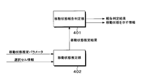
- the radio resource control unit 110 in the present embodiment includes a movement state report determination unit 401 and a movement state estimation unit 402 as shown in FIG.
- the movement state estimation unit 402 estimates the movement state based on the movement state estimation parameter included in the information broadcast from the base station apparatus 2 and the cell information selected by the terminal apparatus 1.
- the movement state estimation result estimated by the movement state estimation unit 402 is input to the movement state report determination unit 401.
- the movement state report determination unit 401 determines whether or not to report the movement state estimation result estimated by the movement state estimation unit 402 to the base station apparatus 2 based on a determination condition described later. Based on the report determination result determined by the movement state report determination unit 401, the radio resource control unit 110 transmits or excludes the movement state estimation result as information indicating the movement state in the RRC connection setting completion message described above. Decide whether to send to.
- the movement state estimation result is information that can identify a plurality of movement states, and may be the same three movement states as before (High-mobility state, Medium-mobility state, and Normal-mobility state). Two movement states (high-speed movement state and non-high-speed movement state) based on the new movement state estimation parameter may be used, or more than three movement states may be used.
- the movement state report determination unit 401 determines to report when the time counted for the number of cells actually selected (including reselection) in the RRC standby state satisfies the evaluation time (t-Evaluation). May be. This prevents the terminal device 1 from making an RRC connection in a state that does not reach the evaluation time, and reporting that the terminal device 1 is neither in the high-mobility state nor the medium-mobility state, that is, in the normal-mobility state. Can do.
- the movement state report determination unit 401 measures the elapsed time after transmitting the information indicating the movement state, and determines to report when the elapsed time satisfies (exceeds) a predetermined time. Also good.
- the movement state report determination unit 401 may measure the elapsed time from the transition from the RRC connected state to the RRC standby state and determine to report when the elapsed time satisfies a predetermined time. Further, even when the predetermined time is not (or does not exceed), a report may be made when the movement state changes. Thereby, the signaling overhead can be reduced.
- a timer is used for each timing, and the terminal device 1 starts (or restarts) the timer when the terminal device 1 transitions to the RRC standby state or transmits information indicating the movement state to the base station device 2. Expires when it reaches the evaluation time (t-Evaluation) or reaches another predetermined value. The terminal device 1 may report when the timer has expired at the time of RRC connection.
- the movement state report determination unit 401 may determine, for each cell, whether or not to report based on the report availability information notified or notified from the base station apparatus 2. This makes it possible to set the necessity of reporting based on the network load status and cell arrangement (for example, there is no small cell in the vicinity and no movement state information is necessary), and reduces signaling overhead. be able to.
- the report availability information may be notified by being included in the system information, may be notified to the terminal device 1 by an RRC connection setting message, or other MAC layer, RRC layer, NAS layer signals and messages. It may be notified by such as.
- the movement state estimation unit 402 is not a conventional movement state estimation, but other additional information (cell type, small cell frequency information, etc.) and measurement values (RSRP, RSRQ, GPS, acceleration sensor, Doppler frequency, etc.) ) Or the like, the movement state report determination unit 401 may determine whether to report based on the estimation method of the movement state estimation unit 402. Furthermore, a reportable estimation method may be specified as reportability information notified or broadcast from the base station apparatus 2. Thereby, for example, it is possible to report only an estimation result obtained by another movement state estimation method without reporting an estimation result to which the conventional movement state estimation is applied. Mobility control can be performed using the state estimation result. Also, signaling overhead can be reduced by preventing unnecessary reporting.
- the movement state estimation unit 402 can estimate the movement state with a plurality of estimation accuracies in accordance with the time and measurement amount for estimating the movement state, the estimation is performed in addition to the movement state estimation result. You may make it report accuracy information. In this case, the movement state report determination unit 401 may determine not to report when any estimation accuracy is not satisfied. Thereby, the base station apparatus 2 can perform mobility control according to the accuracy of the movement state estimation result.
- the moving state estimation result is reported by the determination unit and the moving state is selected from two states (high speed moving state and non-high speed moving state)
- a predetermined state high speed moving state or It is also possible to report only when the state is a non-high-speed movement state. Thereby, it is possible to reduce information to be notified.
- the movement state report determination unit 401 may determine by combining a plurality of the above determination means.
- the base station apparatus 2 can perform mobility control based on an appropriate report.
- terminal device 1 and base station device 2 used in the description of the present embodiment is the same as that in FIG. 1 and FIG. 2 in the first embodiment, detailed description will not be repeated.
- the information indicating the movement state in the present embodiment is also included in the RRC connection setting completion message of FIG. 3 in the first embodiment, detailed description will not be repeated.
- the radio resource control unit 110 in this embodiment includes a movement state report determination unit 501 and a movement state estimation unit 502 as shown in FIG.
- the movement state estimation unit 502 estimates the movement state based on the movement state estimation parameter included in the information broadcast from the base station apparatus 2 and the cell information selected by the terminal apparatus 1.
- the movement state estimation result estimated by the movement state estimation unit 502 and / or information such as parameters used for the estimation are input to the movement state report determination unit 501.
- the movement state report determination unit 501 reports the movement state estimation result estimated by the movement state estimation unit 502 to the base station apparatus 2 or information indicating that the determination condition described later is not satisfied (or the movement state estimation result and the determination condition). Whether to report to the base station device 2 a combination of information indicating that the above is not satisfied is determined based on the determination condition. Based on the report determination result determined by the movement state report determination unit 501, the radio resource control unit 110 transmits information including the movement state in the RRC connection setting completion message described above, or does not satisfy the determination condition. Decide whether to include the information shown.
- the movement state report determination unit 501 satisfies (exceeds) the evaluation time (t-Evaluation (first evaluation time)) when the number of actually selected (and reselected) cells is counted. ) Report the movement state estimation result, and if the evaluation time is not met (does not exceed), the number of cells actually selected (and reselected) is counted as information indicating that the judgment condition is not met.
- the time (t-Evaluation 2 (second evaluation time)) may be reported.
- the base station apparatus 2 can recognize that the determination condition is not satisfied by including t-Evaluation2 in the message.
- the difference between t-Evaluation and t-Evaluation2 may be reported. Further, even when the determination condition is not satisfied, information indicating the movement state may be included in the message in addition to the information indicating that the determination condition is not satisfied.
- the movement state report determination unit 501 detects an estimation result of the movement state estimation unit 502 in a high-mobility state or a medium-mobility state in the RRC standby state, and further detects a high-mobility state or a medium-mobility state.
- t-HystNormal first measurement time
- t-HystNormal2 second measurement time
- t- You may make it report HystNormal2.
- the base station apparatus 2 can recognize whether or not the movement state of the terminal apparatus 1 is close to the normal-mobility state even when the terminal apparatus 1 is in a high-mobility state or a medium-mobility state.
- the movement state estimation can be continued by using t-HystNormal2.
- the movement state report determination unit 501 similarly performs the movement state estimation unit 502 in the RRC standby state. If the estimation result is the High-mobility state and the state in which the High-mobility state is not detected continues for a time less than t-HystNormal, t-HystNormal2 may be reported.
- the movement state report determination unit 501 may determine by combining a plurality of the above determination means.
- the movement state report determination unit 501 may notify at least one bit of information indicating that the determination condition is not satisfied.
- the base station device 2 can identify whether the terminal device 1 does not have the capability of notifying information indicating the movement state or whether it has the capability of notifying but does not satisfy the determination condition for reporting. .
- the first embodiment and the second embodiment may be combined. That is, for example, when the movement state estimation method of the terminal device 1 is the conventional estimation method, the movement state estimation result is not reported, and when the result estimated by the estimation method different from the conventional method satisfies the determination condition The movement state estimation result may be reported, and information indicating that the determination condition is not satisfied may be reported when the determination condition is not satisfied.
- the terminal apparatus 1 when the terminal apparatus 1 does not satisfy the determination condition for reporting the movement state of the own apparatus at the time of RRC connection, the terminal apparatus 1 reports information indicating that the determination condition is not satisfied to the base station apparatus 2. As a result, the base station apparatus 2 can perform mobility control based on an appropriate report.
- terminal device 1 and base station device 2 used in the description of the present embodiment is the same as that in FIG. 1 and FIG. 2 in the first embodiment, detailed description will not be repeated.
- the information indicating the movement state in the present embodiment is also included in the RRC connection setting completion message of FIG. 3 in the first embodiment, detailed description will not be repeated.
- the radio resource control unit 110 in the present embodiment includes a movement state report determination unit 601 and a movement state estimation unit 602 as shown in FIG.
- the movement state estimation unit 602 estimates the movement state based on the movement state estimation parameter included in the information broadcast from the base station apparatus 2 and the cell information selected by the terminal apparatus 1.
- the movement state estimation result estimated by the movement state estimation unit 602 and / or information such as parameters used for the estimation are input to the movement state report determination unit 601.
- the movement state report determination unit 601 receives from the movement state estimation unit 602 history information such as received power (RSRP) and reception quality (RSRQ) of the serving cell, and staying time in the serving cell. Also good.
- RSRP received power
- RSRQ reception quality
- the movement state report determination unit 601 determines the movement state estimation result estimated by the movement state estimation unit 602 based on the determination conditions shown in the first embodiment and the second embodiment. Or whether to report other information to the base station apparatus 2.
- the movement state report determination unit 601 reports the movement state estimation result when the time when the number of actually selected (and reselected) cells is counted satisfies the evaluation time (t-Evaluation) in the RRC standby state.
- history information may be reported as other information.
- the history information includes the identifier of the cell selected (and reselected) in the RRC standby state, the number of selected (and reselected) cells, the identifier of the cell handed over to the RRC connection state, the number of cells handed over, Time information for each selected (and reselected) cell or each handed over cell (time to enter the cell, time to exit from the cell, or stay time in the cell), or a combination thereof.
- the terminal device 1 only when the evaluation time is not satisfied, the terminal device 1 notifies the base station device 2 of detailed history information, whereby the signaling overhead can be reduced.
- the movement state report determination unit 601 determines the movement state estimation result when the time when the number of actually selected (and reselected) cells is counted in the RRC standby state satisfies the evaluation time (t-Evaluation). If the above information is not satisfied, the time when the number of cells is actually counted (t-Evaluation 2) and the number of cells counted during that time, or the identifier information of the counted cells are reported as other information. May be.
- the base station apparatus 2 uses the t-Evaluation 2 and the number of cells or the cell identifier information in the RRC standby state. It is possible to estimate the moving state including information.
- the movement state estimation result is reported, and when the determination condition is not satisfied, other information (for example, history information of the selected cell) is reported, so that the RRC standby state is If the movement state estimation result in the terminal device 1 is long and useful enough, the movement state estimation result is reported. If the RRC standby state is short and the accuracy of the movement state estimation result in the terminal device 1 is poor, By reporting other information (for example, history information of the selected cell) so that the base station apparatus 2 can estimate the movement state of the terminal apparatus 1, the base station apparatus 2 is appropriate for the terminal apparatus 1. Mobility control can be performed.
- other information for example, history information of the selected cell
- the terminal device 1 when reconnecting to the same cell as the cell which carried out the last RRC connection, the terminal device 1 reports when there is a change from the last reported movement state, and when there is no change. May not be reported. Moreover, when using the new movement state estimation method, the terminal device 1 may report information indicating whether the movement state estimation result is estimated by the conventional method or the new method. Further, the terminal device 1 may report history information as other information even when the evaluation time is satisfied.
- the terminal device 1 of the above-described embodiment is not limited to a portable or movable mobile station device, but a stationary or non-movable electronic device installed indoors or outdoors, such as an AV device, a kitchen device, It can also be applied to cleaning / washing equipment, air conditioning equipment, office equipment, vending machines, other life equipment, measuring equipment, and in-vehicle devices.
- the terminal device 1 is also referred to as a user terminal, a mobile station device, a communication terminal, a mobile device, a terminal, a UE (User Equipment), and an MS (Mobile Station).
- the base station apparatus 2 is also referred to as a radio base station apparatus, a base station, a radio base station, a fixed station, an NB (Node-B), an eNB (evolved Node-B), a BTS (Base Transceiver Station), and a BS (Base Station). Is done.
- NB Node-B
- eNB evolved Node-B
- BTS Base Transceiver Station
- BS Base Station
- the base station device 2 and the terminal device 1 of the embodiment have been described using functional block diagrams, but the functions of each part of the base station device 2 and the terminal device 1 or some of these functions are described.
- the method or algorithm steps for implementing may be directly embodied by hardware, software modules executed by a processor, or a combination of the two. If implemented by software, the functions may be maintained or transmitted as one or more instructions or code on a computer-readable medium.
- Computer-readable media includes both communication media and computer recording media including media that facilitate carrying a computer program from one place to another.
- the “computer system” includes an OS and hardware such as peripheral devices.
- a program that operates in the base station apparatus 2 and the terminal apparatus 1 related to each embodiment of the present invention is a program (computer installed) that controls a CPU or the like so as to realize the functions of the above-described embodiments related to each embodiment of the present invention.
- Program to function Information handled by these devices is temporarily stored in the RAM at the time of processing, then stored in various ROMs and HDDs, read out by the CPU, and corrected and written as necessary.
- the processing of the present invention is performed by processing in cooperation with the operating system or other application programs based on the instructions of the program.
- the functions of the embodiments may be realized.
- the “computer-readable recording medium” refers to a semiconductor medium (eg, RAM, nonvolatile memory card, etc.), an optical recording medium (eg, DVD, MO, MD, CD, BD, etc.), a magnetic recording medium (eg, , A magnetic tape, a flexible disk, etc.) and a storage device such as a disk unit built in a computer system.
- the “computer-readable recording medium” means that a program is dynamically held for a short time, like a communication line when a program is transmitted via a network such as the Internet or a communication line such as a telephone line. In this case, it is intended to include those that hold a program for a certain period of time, such as a volatile memory inside a computer system serving as a server or a client in that case.
- the program may be for realizing a part of the above-described functions, and further, may be realized by combining the above-described functions with a program already recorded in a computer system. good.
- each functional block or various features of the base station device 2 and the terminal device 1 used in each of the above embodiments is a general-purpose processor, digital signal processor designed to execute the functions described in this specification.
- DSP digital signal processor
- ASIC application specific or general purpose integrated circuit
- FPGA field programmable gate array signal
- a general purpose processor may be a microprocessor, but in the alternative, the processor may be any conventional processor, controller, microcontroller, or state machine.
- the general-purpose processor or each circuit described above may be configured by a digital circuit or an analog circuit.
- the processor may also be implemented as a combination of computing devices. For example, a DSP and a microprocessor, a plurality of microprocessors, one or more microprocessors connected to a DSP core, or a combination of other such configurations.
- a DSP and a microprocessor for example, a DSP and a microprocessor, a plurality of microprocessors, one or more microprocessors connected to a DSP core, or a combination of other such configurations.
- an integrated circuit based on the technology can also be used.
- One embodiment of the present invention can be applied to a wireless communication system, a terminal device, a base station device, a wireless communication method, an integrated circuit, and the like that need to efficiently notify the base station device of the movement state of the terminal device. .
Abstract
Priority Applications (4)
| Application Number | Priority Date | Filing Date | Title |
|---|---|---|---|
| EP14833966.6A EP3032868A4 (fr) | 2013-08-05 | 2014-07-31 | Système de radiocommunication, appareil terminal, appareil de station de base, procédé de radiocommunication et circuit intégré |
| US14/910,128 US9717103B2 (en) | 2013-08-05 | 2014-07-31 | Wireless communication system, terminal apparatus, base station apparatus, wireless communication method, and integrated circuit |
| JP2015530847A JP6400011B2 (ja) | 2013-08-05 | 2014-07-31 | 無線通信システム、端末装置、基地局装置、無線通信方法および集積回路 |
| US15/655,931 US10397964B2 (en) | 2013-08-05 | 2017-07-21 | Wireless communication system, terminal apparatus, base station apparatus, wireless communication method, and integrated circuit |
Applications Claiming Priority (2)
| Application Number | Priority Date | Filing Date | Title |
|---|---|---|---|
| JP2013-162119 | 2013-08-05 | ||
| JP2013162119 | 2013-08-05 |
Related Child Applications (2)
| Application Number | Title | Priority Date | Filing Date |
|---|---|---|---|
| US14/910,128 A-371-Of-International US9717103B2 (en) | 2013-08-05 | 2014-07-31 | Wireless communication system, terminal apparatus, base station apparatus, wireless communication method, and integrated circuit |
| US15/655,931 Continuation US10397964B2 (en) | 2013-08-05 | 2017-07-21 | Wireless communication system, terminal apparatus, base station apparatus, wireless communication method, and integrated circuit |
Publications (1)
| Publication Number | Publication Date |
|---|---|
| WO2015019930A1 true WO2015019930A1 (fr) | 2015-02-12 |
Family
ID=52461266
Family Applications (1)
| Application Number | Title | Priority Date | Filing Date |
|---|---|---|---|
| PCT/JP2014/070181 WO2015019930A1 (fr) | 2013-08-05 | 2014-07-31 | Système de radiocommunication, appareil terminal, appareil de station de base, procédé de radiocommunication et circuit intégré |
Country Status (4)
| Country | Link |
|---|---|
| US (2) | US9717103B2 (fr) |
| EP (1) | EP3032868A4 (fr) |
| JP (1) | JP6400011B2 (fr) |
| WO (1) | WO2015019930A1 (fr) |
Cited By (1)
| Publication number | Priority date | Publication date | Assignee | Title |
|---|---|---|---|---|
| CN115052322A (zh) * | 2022-06-23 | 2022-09-13 | 北京小米移动软件有限公司 | 触发小区切换的方法、装置、存储介质及芯片 |
Families Citing this family (4)
| Publication number | Priority date | Publication date | Assignee | Title |
|---|---|---|---|---|
| US9717103B2 (en) * | 2013-08-05 | 2017-07-25 | Sharp Kabushiki Kaisha | Wireless communication system, terminal apparatus, base station apparatus, wireless communication method, and integrated circuit |
| US9847823B2 (en) * | 2013-08-08 | 2017-12-19 | Intel IP Corporation | Systems and methods for mobility state estimation framework for LTE network |
| TWI683563B (zh) * | 2014-01-29 | 2020-01-21 | 日商新力股份有限公司 | 在無線電信系統中與基地台通訊的電路、終端裝置、基地台及其操作方法 |
| CN110072285A (zh) * | 2018-01-22 | 2019-07-30 | 维沃移动通信有限公司 | 频域资源的配置方法、终端和基站 |
Citations (1)
| Publication number | Priority date | Publication date | Assignee | Title |
|---|---|---|---|---|
| WO2013022392A1 (fr) * | 2011-08-09 | 2013-02-14 | Telefonaktiebolaget L M Ericsson (Publ) | Échange d'informations de mobilité dans des radiocommunications cellulaires |
Family Cites Families (35)
| Publication number | Priority date | Publication date | Assignee | Title |
|---|---|---|---|---|
| US5189734A (en) * | 1988-11-16 | 1993-02-23 | U.S. Philips Corporation | Cellular radio system |
| US5924042A (en) * | 1995-03-15 | 1999-07-13 | Kabushiki Kaisha Toshiba | Mobile communication system |
| KR100487245B1 (ko) * | 2001-11-28 | 2005-05-03 | 삼성전자주식회사 | 고속 순방향 패킷 접속 방식을 사용하는 이동 통신시스템에서압축 모드에 따른 전송 불능 구간을 최소화하는장치 및 방법 |
| EP1468582B1 (fr) * | 2002-01-22 | 2005-06-22 | Nokia Corporation | Procede, dispositif et systeme d'ajustage de management de mobilite |
| US7254396B2 (en) * | 2002-09-12 | 2007-08-07 | Broadcom Corporation | Network or access point handoff based upon historical pathway |
| US20040224684A1 (en) * | 2003-05-07 | 2004-11-11 | Dorsey Donald A. | Method for a radiotelephone to search for higher priority networks |
| US7536184B2 (en) * | 2005-09-29 | 2009-05-19 | Sun Microsystems, Inc. | Seamless mobility management with service detail records |
| RU2452133C2 (ru) * | 2007-04-26 | 2012-05-27 | Телефонактиеболагет Лм Эрикссон (Пабл) | Способ и устройство для обработки исторической информации по мобильной станции в системе беспроводной связи |
| US8830818B2 (en) * | 2007-06-07 | 2014-09-09 | Qualcomm Incorporated | Forward handover under radio link failure |
| WO2008155915A1 (fr) * | 2007-06-19 | 2008-12-24 | Panasonic Corporation | Procédé d'émission radio, procédé de réception radio, procédé d'émission/réception radio, dispositif d'émission radio, dispositif de réception radio, système d'émission/réception radio, dispositif de station de base et disposit |
| GB0713391D0 (en) * | 2007-07-11 | 2007-08-22 | Vodafone Plc | Measurement and reselection in idle mode |
| CA2712551A1 (fr) * | 2008-01-18 | 2009-08-06 | Telefonaktiebolaget L M Ericsson (Publ) | Procede et appareil de reprise apres defaillance de liaison radio dans un systeme de telecommunication |
| US8639269B2 (en) * | 2008-12-10 | 2014-01-28 | Nec Corporation | Wireless communication system, wireless base station, mobile terminal, wireless communication method, and program |
| US8929894B2 (en) * | 2009-01-06 | 2015-01-06 | Qualcomm Incorporated | Handover failure messaging schemes |
| JPWO2010113490A1 (ja) * | 2009-03-31 | 2012-10-04 | パナソニック株式会社 | 無線通信装置、無線通信基地局、及び無線通信システム |
| US8576714B2 (en) * | 2009-05-29 | 2013-11-05 | Futurewei Technologies, Inc. | System and method for relay node flow control in a wireless communications system |
| CN101909322B (zh) * | 2009-06-03 | 2015-05-20 | 中兴通讯股份有限公司 | 一种移动终端及其上报移动状态的方法 |
| US20100323719A1 (en) * | 2009-06-22 | 2010-12-23 | Yu-Chih Jen | Method of Enhancing Positioning Measurement and Related Communication Device |
| US20110021197A1 (en) * | 2009-07-24 | 2011-01-27 | Qualcomm Incorporated | Apparatus and method for facilitating transfer to a secondary cell |
| EP2494812B1 (fr) * | 2009-10-29 | 2017-08-30 | Nokia Solutions and Networks Oy | Surveillance amelioree de performance de reseau |
| AU2010345442A1 (en) * | 2010-02-10 | 2012-06-28 | Blackberry Limited | Method and apparatus for state/mode transitioning |
| US9226130B2 (en) * | 2010-07-13 | 2015-12-29 | Telefonaktiebolaget L M Ericsson (Publ) | Methods and arrangements relating to mobility control information |
| EP2606686B1 (fr) * | 2010-08-16 | 2019-03-13 | Telefonaktiebolaget LM Ericsson (publ) | Procédé et appareils de commande de puissance à taille de pas variable |
| WO2012045333A1 (fr) * | 2010-10-05 | 2012-04-12 | Nokia Siemens Networks Oy | Gestion de configuration dans des systèmes de communication |
| US8594747B2 (en) * | 2011-05-06 | 2013-11-26 | Apple Inc. | Adaptive fast dormancy in a mobile device |
| CN103959845B (zh) * | 2011-09-30 | 2019-02-01 | 诺基亚通信公司 | 降低无线网络中的无线电链路失效数据量的方法和装置 |
| US9137842B2 (en) * | 2011-10-03 | 2015-09-15 | Mediatek Inc. | Methods of UE providing speed information to network |
| US9137841B2 (en) * | 2011-10-03 | 2015-09-15 | Mediatek Inc. | Enhancement for scheduling request triggering based on traffic condition |
| US9414409B2 (en) * | 2012-02-06 | 2016-08-09 | Samsung Electronics Co., Ltd. | Method and apparatus for transmitting/receiving data on multiple carriers in mobile communication system |
| US20130229931A1 (en) * | 2012-03-02 | 2013-09-05 | Electronics And Telecommunications Research Institute | Methods of managing terminal performed in base station and terminal |
| KR102073223B1 (ko) * | 2012-03-26 | 2020-02-04 | 삼성전자 주식회사 | 이동 통신 시스템에서 단말 상태 천이 시 이동 정보 보존 및 이종 셀 네트워크에서 효과적으로 재 접속하는 방법 및 장치 |
| EP2862336B1 (fr) * | 2012-06-13 | 2016-09-28 | Nokia Technologies Oy | Services en nuage dans des réseaux hétérogènes mobiles |
| US9578486B2 (en) * | 2012-07-12 | 2017-02-21 | Lg Electronics Inc. | Method and apparatus for transmitting mobility related information |
| EP2696644A1 (fr) * | 2012-08-06 | 2014-02-12 | Alcatel-Lucent | Fournir des données sur l'état de mobilité de l'équipement utilisateur au noeud de contrôle du réseau |
| US9717103B2 (en) * | 2013-08-05 | 2017-07-25 | Sharp Kabushiki Kaisha | Wireless communication system, terminal apparatus, base station apparatus, wireless communication method, and integrated circuit |
-
2014
- 2014-07-31 US US14/910,128 patent/US9717103B2/en active Active
- 2014-07-31 WO PCT/JP2014/070181 patent/WO2015019930A1/fr active Application Filing
- 2014-07-31 JP JP2015530847A patent/JP6400011B2/ja active Active
- 2014-07-31 EP EP14833966.6A patent/EP3032868A4/fr not_active Ceased
-
2017
- 2017-07-21 US US15/655,931 patent/US10397964B2/en not_active Expired - Fee Related
Patent Citations (1)
| Publication number | Priority date | Publication date | Assignee | Title |
|---|---|---|---|---|
| WO2013022392A1 (fr) * | 2011-08-09 | 2013-02-14 | Telefonaktiebolaget L M Ericsson (Publ) | Échange d'informations de mobilité dans des radiocommunications cellulaires |
Non-Patent Citations (6)
| Title |
|---|
| 3RD GENERATION PARTNERSHIP PROJECT: "Evolved Universal Terrestrial Radio Access (E-UTRA); Mobility enhancements in heterogeneous networks", 3GPP TR (TECHNICAL REPORT) 36.839, VI 1.1.0 |
| ERICSSON,: "Mobility estimation mechanism in Heterogeneous Networks", R2-131337, 3GPP TSG-RAN WG2#81BIS,, 15 April 2013 (2013-04-15) - 19 April 2013 (2013-04-19) |
| ERICSSON: "Mobility information at RRC Connection Establishment", 3GPP TSG-RAN WG2 #83 TDOC R2-132682, 9 August 2013 (2013-08-09), XP050718280 * |
| MEDIA TEK INC.: "Avoiding Fast UEs in Small Cells", R2-131774, 3GPP TSG-RAN WG2#82,, 20 May 2013 (2013-05-20) - 24 May 2013 (2013-05-24) |
| NOKIA CORPORATION: "Granularity of mobility information", 3GPP TSG-RAN WG2 MEETING #83BIS R2-133384, XP050719027 * |
| See also references of EP3032868A4 |
Cited By (2)
| Publication number | Priority date | Publication date | Assignee | Title |
|---|---|---|---|---|
| CN115052322A (zh) * | 2022-06-23 | 2022-09-13 | 北京小米移动软件有限公司 | 触发小区切换的方法、装置、存储介质及芯片 |
| CN115052322B (zh) * | 2022-06-23 | 2023-10-13 | 北京小米移动软件有限公司 | 触发小区切换的方法、装置、存储介质及芯片 |
Also Published As
| Publication number | Publication date |
|---|---|
| JP6400011B2 (ja) | 2018-10-03 |
| US9717103B2 (en) | 2017-07-25 |
| JPWO2015019930A1 (ja) | 2017-03-02 |
| EP3032868A4 (fr) | 2017-03-15 |
| US10397964B2 (en) | 2019-08-27 |
| US20170318611A1 (en) | 2017-11-02 |
| US20160183314A1 (en) | 2016-06-23 |
| EP3032868A1 (fr) | 2016-06-15 |
Similar Documents
| Publication | Publication Date | Title |
|---|---|---|
| JP6797120B2 (ja) | 端末装置、基地局装置、方法および電気回路 | |
| US9907079B2 (en) | Communication system, mobile station apparatus, radio link state management method, and integrated circuit | |
| US10721659B2 (en) | Radio communication system, terminal device, base station device, radio communication method, and integrated circuit | |
| US9913287B2 (en) | Terminal apparatus, base station apparatus, and control methods for secondary cells | |
| CN104412657B (zh) | 终端装置、基站装置、小区选择方法以及集成电路 | |
| WO2017026415A1 (fr) | Dispositif terminal, dispositif de station de base, système de communication, procédé de mesure, et circuit intégré | |
| JP6421389B2 (ja) | 端末装置および通信方法 | |
| US10064163B2 (en) | Terminal apparatus, base station apparatus, communication system, control method, and integrated circuit | |
| JP6147961B2 (ja) | 移動局装置、基地局装置、送受信制御方法および集積回路 | |
| US9820278B2 (en) | Terminal apparatus, base station apparatus, communication system, communication method and integrated circuit | |
| US10397964B2 (en) | Wireless communication system, terminal apparatus, base station apparatus, wireless communication method, and integrated circuit | |
| JP2013042258A (ja) | 移動局装置、基地局装置、通信システム、上りリンク送信制御方法および集積回路 | |
| JP2013042259A (ja) | 移動局装置、基地局装置、通信システム、上りリンク送信制御方法および集積回路 | |
| JP2014146865A (ja) | 端末装置、基地局装置、通信システム、測定方法および集積回路 | |
| WO2014156826A1 (fr) | Système de communication sans fil, appareil de terminal, appareil de station de base, procédé de communication sans fil et circuit intégré | |
| WO2014010477A1 (fr) | Système de communication, station de base, station mobile, procédé de mesure, et circuit intégré | |
| JP2014023017A (ja) | 移動局装置、基地局装置、通信システム、通信方法および集積回路 | |
| JP2017038117A (ja) | 端末装置、基地局装置、通信システム、通知方法および集積回路 | |
| WO2013168697A1 (fr) | Appareil de station mobile, appareil de station de base, système de communication, procédé de requête de ressources radio et circuit intégré |
Legal Events
| Date | Code | Title | Description |
|---|---|---|---|
| 121 | Ep: the epo has been informed by wipo that ep was designated in this application |
Ref document number: 14833966 Country of ref document: EP Kind code of ref document: A1 |
|
| ENP | Entry into the national phase |
Ref document number: 2015530847 Country of ref document: JP Kind code of ref document: A |
|
| WWE | Wipo information: entry into national phase |
Ref document number: 14910128 Country of ref document: US Ref document number: 2014833966 Country of ref document: EP |
|
| NENP | Non-entry into the national phase |
Ref country code: DE |