WO2015019901A1 - Centrifugal compressor and supercharger - Google Patents

Centrifugal compressor and supercharger Download PDF

Info

Publication number
WO2015019901A1
WO2015019901A1 PCT/JP2014/069936 JP2014069936W WO2015019901A1 WO 2015019901 A1 WO2015019901 A1 WO 2015019901A1 JP 2014069936 W JP2014069936 W JP 2014069936W WO 2015019901 A1 WO2015019901 A1 WO 2015019901A1
Authority
WO
WIPO (PCT)
Prior art keywords
diffuser
wall surface
side wall
centrifugal compressor
housing
Prior art date
Application number
PCT/JP2014/069936
Other languages
French (fr)
Japanese (ja)
Inventor
保孝 別所
Original Assignee
株式会社Ihi
Priority date (The priority date is an assumption and is not a legal conclusion. Google has not performed a legal analysis and makes no representation as to the accuracy of the date listed.)
Filing date
Publication date
Application filed by 株式会社Ihi filed Critical 株式会社Ihi
Priority to JP2015530830A priority Critical patent/JP6323454B2/en
Priority to EP14834428.6A priority patent/EP3032108B8/en
Priority to CN201480032889.XA priority patent/CN105339675A/en
Publication of WO2015019901A1 publication Critical patent/WO2015019901A1/en
Priority to US14/950,094 priority patent/US10066638B2/en

Links

Images

Classifications

    • FMECHANICAL ENGINEERING; LIGHTING; HEATING; WEAPONS; BLASTING
    • F04POSITIVE - DISPLACEMENT MACHINES FOR LIQUIDS; PUMPS FOR LIQUIDS OR ELASTIC FLUIDS
    • F04DNON-POSITIVE-DISPLACEMENT PUMPS
    • F04D29/00Details, component parts, or accessories
    • F04D29/40Casings; Connections of working fluid
    • F04D29/42Casings; Connections of working fluid for radial or helico-centrifugal pumps
    • F04D29/44Fluid-guiding means, e.g. diffusers
    • F04D29/441Fluid-guiding means, e.g. diffusers especially adapted for elastic fluid pumps
    • FMECHANICAL ENGINEERING; LIGHTING; HEATING; WEAPONS; BLASTING
    • F02COMBUSTION ENGINES; HOT-GAS OR COMBUSTION-PRODUCT ENGINE PLANTS
    • F02BINTERNAL-COMBUSTION PISTON ENGINES; COMBUSTION ENGINES IN GENERAL
    • F02B33/00Engines characterised by provision of pumps for charging or scavenging
    • F02B33/32Engines with pumps other than of reciprocating-piston type
    • F02B33/34Engines with pumps other than of reciprocating-piston type with rotary pumps
    • F02B33/40Engines with pumps other than of reciprocating-piston type with rotary pumps of non-positive-displacement type
    • FMECHANICAL ENGINEERING; LIGHTING; HEATING; WEAPONS; BLASTING
    • F04POSITIVE - DISPLACEMENT MACHINES FOR LIQUIDS; PUMPS FOR LIQUIDS OR ELASTIC FLUIDS
    • F04DNON-POSITIVE-DISPLACEMENT PUMPS
    • F04D17/00Radial-flow pumps, e.g. centrifugal pumps; Helico-centrifugal pumps
    • F04D17/08Centrifugal pumps
    • F04D17/10Centrifugal pumps for compressing or evacuating
    • FMECHANICAL ENGINEERING; LIGHTING; HEATING; WEAPONS; BLASTING
    • F04POSITIVE - DISPLACEMENT MACHINES FOR LIQUIDS; PUMPS FOR LIQUIDS OR ELASTIC FLUIDS
    • F04DNON-POSITIVE-DISPLACEMENT PUMPS
    • F04D25/00Pumping installations or systems
    • F04D25/02Units comprising pumps and their driving means
    • F04D25/024Units comprising pumps and their driving means the driving means being assisted by a power recovery turbine
    • FMECHANICAL ENGINEERING; LIGHTING; HEATING; WEAPONS; BLASTING
    • F04POSITIVE - DISPLACEMENT MACHINES FOR LIQUIDS; PUMPS FOR LIQUIDS OR ELASTIC FLUIDS
    • F04DNON-POSITIVE-DISPLACEMENT PUMPS
    • F04D29/00Details, component parts, or accessories
    • F04D29/26Rotors specially for elastic fluids
    • F04D29/28Rotors specially for elastic fluids for centrifugal or helico-centrifugal pumps for radial-flow or helico-centrifugal pumps
    • F04D29/284Rotors specially for elastic fluids for centrifugal or helico-centrifugal pumps for radial-flow or helico-centrifugal pumps for compressors
    • FMECHANICAL ENGINEERING; LIGHTING; HEATING; WEAPONS; BLASTING
    • F04POSITIVE - DISPLACEMENT MACHINES FOR LIQUIDS; PUMPS FOR LIQUIDS OR ELASTIC FLUIDS
    • F04DNON-POSITIVE-DISPLACEMENT PUMPS
    • F04D29/00Details, component parts, or accessories
    • F04D29/40Casings; Connections of working fluid
    • F04D29/42Casings; Connections of working fluid for radial or helico-centrifugal pumps
    • F04D29/4206Casings; Connections of working fluid for radial or helico-centrifugal pumps especially adapted for elastic fluid pumps
    • FMECHANICAL ENGINEERING; LIGHTING; HEATING; WEAPONS; BLASTING
    • F04POSITIVE - DISPLACEMENT MACHINES FOR LIQUIDS; PUMPS FOR LIQUIDS OR ELASTIC FLUIDS
    • F04DNON-POSITIVE-DISPLACEMENT PUMPS
    • F04D29/00Details, component parts, or accessories
    • F04D29/66Combating cavitation, whirls, noise, vibration or the like; Balancing
    • F04D29/68Combating cavitation, whirls, noise, vibration or the like; Balancing by influencing boundary layers
    • F04D29/681Combating cavitation, whirls, noise, vibration or the like; Balancing by influencing boundary layers especially adapted for elastic fluid pumps
    • FMECHANICAL ENGINEERING; LIGHTING; HEATING; WEAPONS; BLASTING
    • F02COMBUSTION ENGINES; HOT-GAS OR COMBUSTION-PRODUCT ENGINE PLANTS
    • F02BINTERNAL-COMBUSTION PISTON ENGINES; COMBUSTION ENGINES IN GENERAL
    • F02B37/00Engines characterised by provision of pumps driven at least for part of the time by exhaust
    • FMECHANICAL ENGINEERING; LIGHTING; HEATING; WEAPONS; BLASTING
    • F05INDEXING SCHEMES RELATING TO ENGINES OR PUMPS IN VARIOUS SUBCLASSES OF CLASSES F01-F04
    • F05DINDEXING SCHEME FOR ASPECTS RELATING TO NON-POSITIVE-DISPLACEMENT MACHINES OR ENGINES, GAS-TURBINES OR JET-PROPULSION PLANTS
    • F05D2220/00Application
    • F05D2220/40Application in turbochargers
    • FMECHANICAL ENGINEERING; LIGHTING; HEATING; WEAPONS; BLASTING
    • F05INDEXING SCHEMES RELATING TO ENGINES OR PUMPS IN VARIOUS SUBCLASSES OF CLASSES F01-F04
    • F05DINDEXING SCHEME FOR ASPECTS RELATING TO NON-POSITIVE-DISPLACEMENT MACHINES OR ENGINES, GAS-TURBINES OR JET-PROPULSION PLANTS
    • F05D2250/00Geometry
    • F05D2250/50Inlet or outlet
    • F05D2250/52Outlet

Definitions

  • the present invention relates to a centrifugal compressor that uses a centrifugal force to compress fluid (including gas such as air), and more particularly to a diffuser in the centrifugal compressor.
  • a typical centrifugal compressor has a housing.
  • the housing has a shroud inside.
  • an impeller is rotatably provided about its axis.
  • the impeller is equipped with a disc.
  • the hub surface of the disk extends radially outward from one axial side of the turbine impeller.
  • a plurality of blades are integrally provided circumferentially spaced on the hub surface of the disk. The leading edge of each blade extends along the shroud of the housing.
  • annular diffuser diffuser channel
  • scroll scroll flow passage
  • an object of the present invention is to provide a centrifugal compressor and a supercharger which can solve the above-mentioned problem.
  • a centrifugal compressor for compressing fluid (including gas such as air) using centrifugal force, comprising: a housing having a shroud inside; and rotatable in the housing An impeller provided, a diffuser (diffuser channel) formed radially outward on the outlet side of the impeller in the housing, and a scroll (scroll channel) formed on the outlet side of the diffuser in the housing And the shroud side wall surface and the hub side wall surface of the diffuser respectively extend in the radial direction, and at least one stepped portion on the shroud side wall surface of the diffuser in the main flow direction of the flow path width of the diffuser
  • the gist is that it is formed to be spread along.
  • “provided” includes not only directly provided but also indirectly provided via another member, “Integrally provided” is meant to include integrally formed.
  • “axial direction” refers to the axial direction of the impeller, and “radial direction” refers to the radial direction of the impeller.
  • shroud side wall surface refers to a wall surface located on the radially outward extending surface of the shroud of the housing, and “hub side wall surface” extends radially outward the hub surface of the disk. It refers to the wall located on the surface side.
  • a second aspect of the present invention is a supercharger, comprising the centrifugal compressor according to the first aspect.
  • the centrifugal compressor during the operation of the centrifugal compressor, the development of separation on the outlet side of the shroud side wall surface of the diffuser can be suppressed. Therefore, the main flow can be sufficiently decelerated by the diffuser while suppressing a decrease in the effective flow passage area on the outlet side of the diffuser. Further, during operation of the centrifugal compressor, the low pressure portion due to flow separation can be reduced at the outlet side of the shroud side wall surface of the diffuser. Therefore, the collision (interference) between the low pressure portion and the main flow in the scroll can be alleviated, and the occurrence of disturbance in the main flow on the downstream side of the scroll can be suppressed. Therefore, according to the present invention, the compressor efficiency of the centrifugal compressor can be improved while enhancing the static pressure recovery performance of the diffuser.
  • FIG. 1 is an enlarged view of an arrow portion I in FIG. Fig.2 (a) is an enlarged view of arrow part II in FIG. 1
  • FIG.2 (b) and FIG.2 (c) are figures which show a different aspect of a level
  • FIG. 3 is a front sectional view showing a centrifugal compressor and the like according to an embodiment of the present invention.
  • Fig.4 (a) is a schematic diagram which shows the structure of the periphery of the diffuser which concerns on an invention example
  • FIG.4 (b) is a schematic diagram which shows the structure of the periphery of the diffuser which concerns on a comparative example.
  • FIG. 5 (a) and 5 (b) are diagrams showing an area where a low pressure portion is generated in the operation area on the large flow rate side (choke side), and FIG. Is the case of the comparative example.
  • 6 (a) and 6 (b) are diagrams showing static pressure distributions in the scroll and the diffuser in the working area near the peak of the compressor efficiency, and
  • FIG. b) is a case of a comparative example.
  • FIG. 7 is a view showing the relationship between the flow rate and the compressor efficiency in the invention example and the comparative example.
  • the present invention is based on the following new findings.
  • the novel finding is that the annular step portion 35 is formed.
  • Development of flow separation (peeling vortices) is suppressed at the outlet 27o side of the shroud side wall surface 27s of the diffuser 27 during operation of the centrifugal compressor, as compared to the case where no is formed (see FIG. 4 (b))
  • the low pressure portion LP due to the peeling is reduced (see FIGS. 5A and 5B).
  • FIG. 4A is a schematic view showing the configuration around the diffuser 27 according to the invention example.
  • FIG. 4B is a schematic view showing the configuration around the diffuser 27 according to the comparative example.
  • 5 (a) and 5 (b) are diagrams showing a region where a low pressure portion is generated in the operation region on the large flow rate side (choke side)
  • FIG. 5 (a) is a diagram in the case of the invention example.
  • 5 (b) is the case of the comparative example.
  • the region where the low pressure portion LP is generated is obtained by computational fluid analysis (CFD: Computational Fluid Dynamics analysis).
  • CFD computational Fluid Dynamics analysis
  • FIGS. 1 to 3 As shown in the drawings, “L” is in the left direction, and “R” is in the right direction.
  • the centrifugal compressor 1 which concerns on embodiment of this invention is used for the supercharger 3, and compresses air using a centrifugal force.
  • the centrifugal compressor 1 includes a housing (compressor housing) 5.
  • the housing 5 includes a housing body 7 having a shroud 7 s inside, and a seal plate 9 provided on the right side of the housing body 7.
  • the seal plate 9 is integrally connected to another housing (bearing housing) 11 in the turbocharger 3.
  • an impeller (compressor impeller) 13 is rotatably provided about its axis C.
  • the impeller 13 is integrally connected to the left end of the rotating shaft 19.
  • the rotating shaft 19 is rotatably provided in another housing 11 via a plurality of thrust bearings 15 and a plurality (only one is shown) of radial bearings 17.
  • the impeller 13 also includes a disk 21.
  • the disk 21 has a hub surface 21 h.
  • the hub surface 21 h extends outward in the radial direction (radial direction of the impeller 13) from the left direction (one side in the axial direction of the impeller 13).
  • a plurality of blades 23 having the same axial length are integrally formed on the hub surface 21 h of the disk 21 at intervals in the circumferential direction.
  • the leading edge 23 t of each blade 23 extends along the shroud 7 s of the housing body 7. Note that, instead of using a plurality of blades 23 having the same axial length, a plurality of blades (not shown) having different axial lengths may be used.
  • An inlet (introduction channel) 25 is formed on the inlet side of the impeller 13 in the housing body 7.
  • the inlet 25 introduces air into the housing 5. Further, the inlet 25 is connected to an air cleaner (not shown) for purifying the air.
  • a diffuser (diffuser channel) 27 is formed on the outlet side of the impeller 13 in the housing 5. The diffuser 27 decelerates and boosts the compressed air (compressed air).
  • the diffuser 27 is formed, for example, in an annular shape.
  • a throttle portion (throttling channel) 29 is formed between the impeller 13 and the diffuser 27 in the housing 5. The flow passage width of the throttling portion 29 gradually decreases along the main flow direction.
  • the throttling portion 29 is formed, for example, in an annular shape.
  • the throttling portion 29 communicates with the diffuser 27.
  • a scroll (scroll flow path) 31 is formed on the outlet side of the diffuser 27 in the housing 5.
  • the scroll 31 is formed in a spiral shape.
  • the scroll 31 is in communication with the diffuser 27.
  • the cross-sectional area of the scroll 31 is larger at the winding end side (downstream side) than at the winding start side (upstream side).
  • a discharge port (discharge flow path) 33 is formed at an appropriate position of the housing body 7.
  • the discharge port 33 discharges the compressed air to the outside of the housing 5.
  • the discharge port 33 communicates with the scroll 31 and is connected to an engine-side intake pipe (not shown) such as an intake manifold or an intercooler of the engine.
  • the shroud side wall surface 27s and the hub side wall surface 27h of the diffuser 27 are provided to extend in the radial direction (the radial direction of the impeller 13). For example, they may be parallel to the radial direction.
  • the shroud side wall surface 27s refers to a wall surface located on the radially outer side of the shroud 7s of the housing body 7.
  • the hub side wall surface 27 h refers to a wall surface located on the side where the hub surface 21 h of the disk 21 extends radially outward.
  • the above-mentioned parallelism does not have to be exact. That is, the shroud side wall surface 27s and the hub side wall surface 27h may be inclined at an angle of several degrees with respect to the radial direction.
  • a plurality of annular step portions 35 are formed in the middle of the shroud side wall surface 27s of the diffuser 27 (between the inlet 27i and the outlet 27o of the diffuser 27). Each step 35 is formed to extend the flow passage width of the diffuser 27 along the main flow direction. Each step 35 locally generates a separation vortex. Each stepped portion 35 is parallel to the flow passage width direction (left and right direction) of the diffuser 27. However, as shown to FIG. 2B, you may incline in linear or curvilinear form with respect to the flow-path width direction of the diffuser 27. As shown in FIG. Furthermore, as shown in FIG. 2C, the number of step portions 35 may be single (one). Here, the above-mentioned parallelism does not have to be exact.
  • the step 35 need not be a continuous ring.
  • the stepped portion 35 may be provided only in a specific circumferential direction area, such as near the tongue portion on the scroll winding end side.
  • machining becomes easy.
  • the number of stepped portions 35 can be arbitrarily selected in accordance with engine specifications. However, for example, a single step portion 35 can exert effects on pinpoints in a specific operation region, and by providing a plurality of step portions 35, a single operation in a relatively wide range of operation region, It can be effective.
  • two stepped portions 35 can be provided as an example in which a plurality of stepped portions 35 are provided. By providing the two step portions 35, it is possible to minimize the time and effort required for processing the step portions, and to exhibit the effect in a wide range as compared with a single step.
  • the step amount ⁇ of the step portion 35 is 5 to 30%, preferably 10 to 20% (0.05 to 0.30 times, preferably 0.10 to 0.3) of the flow path width ⁇ of the outlet 27 o of the diffuser 27. It is set to 20 times). If the step amount ⁇ is set to 5% or more of the flow path width ⁇ , if it is less than 5%, a peeling vortex with sufficient strength (vortex) near the step portion 35 is locally generated. Because it may be difficult. On the other hand, the step amount ⁇ is set to less than 30% of the flow channel width ⁇ because if it exceeds 30%, there is a possibility that the peeling vortices (peeling) generated by the step portion 35 may increase.
  • the shroud side wall surface 27 s of the diffuser 27 has a portion that is continuous (adjacent) to the radially outer side of the stepped portion 35.
  • the radial length ⁇ of this portion is set to 5 to 30 times, preferably 10 to 20 times, the step amount ⁇ of the step portion 35.
  • the length ⁇ is set to five times or more of the step amount ⁇ , it is less than five times that the main flow along the shroud sidewall surface 27s of the diffuser 27 on the front side of the outlet 27o of the diffuser 27 It may be difficult to On the other hand, when the length ⁇ is set to 30 times or less of the step portion 35, if it exceeds 30 times, a new flow of separation vortex (peeling off the front side of the outlet 27o of the diffuser 27 on the shroud side wall surface 27s of the diffuser 27) ), And the effective flow area in the diffuser 27 may be reduced.
  • Air introduced into the housing 5 from the inlet 25 can be compressed by rotating the impeller 13 integrally with the rotation shaft 19 around its axis by driving of a radial turbine (not shown) in the turbocharger 3. it can. Then, the compressed air (compressed air) is boosted while being decelerated by the diffuser 27, and is discharged to the outside of the housing 5 from the discharge port 33 via the scroll 31.
  • the shroud side wall surface 27s and the hub side wall surface 27h of the diffuser 27 are respectively parallel to the radial direction. Further, an annular step portion 35 is formed at an intermediate portion of the shroud side wall surface 27s of the diffuser 27 so as to expand the flow passage width of the diffuser 27 along the main flow direction. Therefore, applying the above-mentioned new findings, during the operation of the centrifugal compressor 1 (the operation of the supercharger 3), the development of flow separation (a separation vortex) at the outlet 27o side of the diffuser 27 in the shroud side wall surface 27s. Can be reduced, and the low pressure part (blockage, low pressure area, closed area) due to the exfoliation can be reduced.
  • the embodiment of the present invention it is possible to suppress the development of flow separation on the outlet side 27 o of the diffuser 27 at the shroud side wall surface 27 s during operation of the centrifugal compressor 1. Therefore, the reduction of the effective flow passage area on the outlet 27o side of the diffuser 27 can be suppressed. Therefore, the main flow can be sufficiently decelerated by the diffuser 27. In addition, during operation of the centrifugal compressor 1, the low pressure portion LP can be reduced due to flow separation on the outlet 27o side of the diffuser 27 at the shroud side wall surface 27s.
  • the collision (interference) between the low pressure portion LP and the main flow in the scroll 31 is alleviated, and the occurrence of disturbance in the main flow in the discharge port 33 located on the downstream side of the scroll 31 can be suppressed. it can. Therefore, according to the embodiment of the present invention, the compressor efficiency of the centrifugal compressor 1 can be improved while improving the static pressure recovery performance of the diffuser 27.
  • the present invention is not limited to the description of the above-described embodiment.
  • the technical idea applied to the centrifugal compressor 1 may be applied to a gas turbine, an industrial air facility, etc.
  • the present invention can be implemented in various other manners, such as disposing (not shown) at intervals in the circumferential direction. Further, the scope of rights included in the present invention is not limited to these embodiments.
  • FIG. 6 Embodiments of the present invention will be described with reference to FIGS. 6 (a), 6 (b) and 7.
  • FIG. 6 (a), 6 (b) and 7. FIG. 6

Abstract

An annular diffuser (27) is formed on an outlet side of an impeller (13) that is inside a housing (5). A shroud-side wall surface (27s) and a hub-side wall surface (27h) of the diffuser (27) are each parallel to the radial direction. A plurality of annular step parts (35) are formed on the shroud-side wall surface (27s) of the diffuser (27). Each step part (35) is formed such that the channel width of the diffuser (27) widens along the direction of the mainstream flow.

Description

遠心圧縮機及び過給機Centrifugal compressor and supercharger
 本発明は、遠心力を利用して流体(空気等のガスを含む)を圧縮する遠心圧縮機、特に、遠心圧縮機におけるディフューザに関するものである。 The present invention relates to a centrifugal compressor that uses a centrifugal force to compress fluid (including gas such as air), and more particularly to a diffuser in the centrifugal compressor.
 近年、過給機、ガスタービン、産業用空気設備等に用いられる遠心圧縮機について種々の研究開発がなされている。(特許文献1~特許文献3参照)。 In recent years, various researches and developments have been made on centrifugal compressors used for turbochargers, gas turbines, industrial air equipment, and the like. (See Patent Document 1 to Patent Document 3).
 一般的な遠心圧縮機は、ハウジングを具備している。このハウジングは、内側にシュラウドを有している。ハウジング内には、インペラがその軸心周りに回転可能に設けられている。インペラはディスクを備えている。このディスクのハブ面は、タービンインペラの軸方向一方側から径方向外側に向かって延びている。ディスクのハブ面には、複数のブレードが周方向に間隔を置いて一体的に設けられている。各ブレードの先端縁は、ハウジングのシュラウドに沿うように延びている。 A typical centrifugal compressor has a housing. The housing has a shroud inside. In the housing, an impeller is rotatably provided about its axis. The impeller is equipped with a disc. The hub surface of the disk extends radially outward from one axial side of the turbine impeller. A plurality of blades are integrally provided circumferentially spaced on the hub surface of the disk. The leading edge of each blade extends along the shroud of the housing.
 ハウジング内におけるインペラの出口側には、圧縮した流体(圧縮流体)を減速させて昇圧する環状のディフューザ(ディフューザ流路)が形成されている。また、ハウジング内におけるディフューザの出口側には、ディフューザに連通したスクロール(スクロール流路)が形成されている。 At the outlet side of the impeller in the housing, an annular diffuser (diffuser channel) is formed which decelerates and pressurizes the compressed fluid (compressed fluid). Further, a scroll (scroll flow passage) communicating with the diffuser is formed on the outlet side of the diffuser in the housing.
特開2009-2305号公報JP, 2009-2305, A 特開2006-220053号公報JP, 2006-220053, A 特開2010-196542号公報JP, 2010-196542, A
 ところで、遠心圧縮機の運転中に、ディフューザのシュラウド側壁面の出口側において、流路形状の急激な変化に伴う流れの剥離(剥離渦)が発生する。一方、流れの剥離が発達すると、ディフューザの出口側における有効流路面積が減少する。その結果、ディフューザによって主流の流れを十分に減速させることができず、ディフューザの静圧回復性能が低下する。また、ディフューザのシュラウド側壁面の出口側における流れの剥離による低圧部(ブロッケージ、低圧領域、閉塞領域)とスクロール内の主流の流れとの衝突(干渉)によって、スクロールの下流側に位置する吐出口(吐出流路)内の流れに乱れが生じて、遠心圧縮機の圧縮機効率が低下する。 By the way, during operation of the centrifugal compressor, flow separation (a separation vortex) is generated along with a rapid change of the flow path shape on the outlet side of the shroud side wall surface of the diffuser. On the other hand, as flow separation develops, the effective flow area at the outlet side of the diffuser decreases. As a result, the main flow can not be sufficiently decelerated by the diffuser, and the static pressure recovery performance of the diffuser is degraded. In addition, the discharge port located on the downstream side of the scroll due to the collision (interference) between the low pressure portion (blockage, low pressure area, closed area) and the mainstream flow in the scroll due to flow separation on the outlet side of the shroud side wall surface of the diffuser. The flow in the (discharge flow path) is disturbed to reduce the compressor efficiency of the centrifugal compressor.
 そこで、本発明は、前述の問題を解決することができる遠心圧縮機及び過給機を提供することを目的とする。 Then, an object of the present invention is to provide a centrifugal compressor and a supercharger which can solve the above-mentioned problem.
 本発明の第1の態様は、遠心力を利用して流体(空気等のガスを含む)を圧縮する遠心圧縮機であって、内側にシュラウドを有したハウジングと、前記ハウジング内に回転可能に設けられたインペラと、前記ハウジング内における前記インペラの出口側の径方向外側に形成されたディフューザ(ディフューザ流路)と、前記ハウジング内における前記ディフューザの出口側に形成されたスクロール(スクロール流路)とを具備し、前記ディフューザのシュラウド側壁面及びハブ側壁面は、径方向にそれぞれ延在し、前記ディフューザのシュラウド側壁面に少なくとも1つの段差部が前記ディフューザの流路幅を主流の流れ方向に沿って広げるように形成されていることを要旨とする。 According to a first aspect of the present invention, there is provided a centrifugal compressor for compressing fluid (including gas such as air) using centrifugal force, comprising: a housing having a shroud inside; and rotatable in the housing An impeller provided, a diffuser (diffuser channel) formed radially outward on the outlet side of the impeller in the housing, and a scroll (scroll channel) formed on the outlet side of the diffuser in the housing And the shroud side wall surface and the hub side wall surface of the diffuser respectively extend in the radial direction, and at least one stepped portion on the shroud side wall surface of the diffuser in the main flow direction of the flow path width of the diffuser The gist is that it is formed to be spread along.
 なお、本願の明細書及び特許請求の範囲において、「設けられ」とは、直接的に設けられたことの他に、別部材を介して間接的に設けられたことを含む意であって、「一体的に設けられ」とは、一体形成されたことを含む意である。また、「軸方向」とは、インペラの軸方向のことをいい、「径方向」とは、インペラの径方向のことをいう。更に、「シュラウド側壁面」とは、ハウジングのシュラウドを径方向外側へ延長した面側に位置する壁面のことをいい、「ハブ側壁面」とは、ディスクのハブ面を径方向外側へ延長した面側に位置する壁面のことをいう。 In the specification and claims of the present application, “provided” includes not only directly provided but also indirectly provided via another member, "Integrally provided" is meant to include integrally formed. Also, "axial direction" refers to the axial direction of the impeller, and "radial direction" refers to the radial direction of the impeller. Furthermore, "shroud side wall surface" refers to a wall surface located on the radially outward extending surface of the shroud of the housing, and "hub side wall surface" extends radially outward the hub surface of the disk. It refers to the wall located on the surface side.
 本発明の第2の態様は、過給機であって、第1の態様に係る遠心圧縮機を具備したことを要旨とする。 A second aspect of the present invention is a supercharger, comprising the centrifugal compressor according to the first aspect.
 本発明によれば、前記遠心圧縮機の運転中に、前記ディフューザのシュラウド側壁面の出口側の剥離の発達を抑えることができる。そのため、前記ディフューザの出口側の有効流路面積の減少を抑えて、前記ディフューザによって主流の流れを十分に減速させることができる。また、前記遠心圧縮機の運転中に、前記ディフューザのシュラウド側壁面の出口側において、流れの剥離による低圧部を縮小できる。そのため、その低圧部と前記スクロール内の主流の流れとの衝突(干渉)を緩和して、前記スクロールの下流側における主流の流れに乱れが生じることを抑えることができる。よって、本発明によれば、前記ディフューザの静圧回復性能を高めつつ、前記遠心圧縮機の圧縮機効率の向上を図ることができる。 According to the present invention, during the operation of the centrifugal compressor, the development of separation on the outlet side of the shroud side wall surface of the diffuser can be suppressed. Therefore, the main flow can be sufficiently decelerated by the diffuser while suppressing a decrease in the effective flow passage area on the outlet side of the diffuser. Further, during operation of the centrifugal compressor, the low pressure portion due to flow separation can be reduced at the outlet side of the shroud side wall surface of the diffuser. Therefore, the collision (interference) between the low pressure portion and the main flow in the scroll can be alleviated, and the occurrence of disturbance in the main flow on the downstream side of the scroll can be suppressed. Therefore, according to the present invention, the compressor efficiency of the centrifugal compressor can be improved while enhancing the static pressure recovery performance of the diffuser.
図1は、図3における矢視部Iの拡大図である。FIG. 1 is an enlarged view of an arrow portion I in FIG. 図2(a)は、図1における矢視部IIの拡大図、図2(b)及び図2(c)は、段差部の異なる態様を示す図である。Fig.2 (a) is an enlarged view of arrow part II in FIG. 1, FIG.2 (b) and FIG.2 (c) are figures which show a different aspect of a level | step-difference part. 図3は、本発明の実施形態に係る遠心圧縮機等を示す正断面図である。FIG. 3 is a front sectional view showing a centrifugal compressor and the like according to an embodiment of the present invention. 図4(a)は、発明例に係るディフューザの周辺の構成を示す模式図、図4(b)は、比較例に係るディフューザの周辺の構成を示す模式図である。Fig.4 (a) is a schematic diagram which shows the structure of the periphery of the diffuser which concerns on an invention example, FIG.4 (b) is a schematic diagram which shows the structure of the periphery of the diffuser which concerns on a comparative example. 図5(a)及び図5(b)は、大流量側(チョーク側)の作動域において低圧部が生成される領域を示す図、図5(a)が発明例の場合、図5(b)が比較例の場合である。5 (a) and 5 (b) are diagrams showing an area where a low pressure portion is generated in the operation area on the large flow rate side (choke side), and FIG. Is the case of the comparative example. 図6(a)及び図6(b)は、圧縮機効率のピーク付近の作動域におけるスクロール内及びディフューザ内の静圧分布を示す図、図6(a)が発明例の場合、図6(b)が比較例の場合である。6 (a) and 6 (b) are diagrams showing static pressure distributions in the scroll and the diffuser in the working area near the peak of the compressor efficiency, and FIG. b) is a case of a comparative example. 図7は、発明例及び比較例における流量と圧縮機効率との関係を示す図である。FIG. 7 is a view showing the relationship between the flow rate and the compressor efficiency in the invention example and the comparative example.
 本発明は、次に述べる新規な知見に基づいている。 The present invention is based on the following new findings.
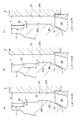
 即ち、その新規な知見とは、所定の条件の下で、ディフューザ27のシュラウド側壁面27sに環状の段差部35が形成された場合(図4(a)参照)には、環状の段差部35が形成されていない場合(図4(b)参照)に比べて、遠心圧縮機の運転中に、ディフューザ27のシュラウド側壁面27sの出口27o側において、流れの剥離(剥離渦)の発達が抑えられ、これにより、その剥離による低圧部LPが縮小されるというものである(図5(a)及び図5(b)参照)。これは、環状の段差部35近傍に剥離渦を局所的に発生させて、ディフューザ27のシュラウド側壁面27s近傍に低圧部LPを生成したことにより、ディフューザ27の出口27oの手前側において主流の流れがディフューザ27のシュラウド側壁面27sに沿い易くなったことによるものと考えられる。また、所定の条件とは、ディフューザ27のシュラウド側壁面27s及びハブ側壁面27hがインペラの径方向に対してそれぞれ平行であること、及び環状の段差部35がディフューザ27の流路幅を主流の流れ方向に沿って広げるようになっていることである。なお、図4(a)及び図4(b)における符号27iは、インペラ13の収容室(図1参照)に連通するディフューザ27の入口を示している。 That is, when the annular step portion 35 is formed on the shroud side wall surface 27s of the diffuser 27 under a predetermined condition (see FIG. 4A), the novel finding is that the annular step portion 35 is formed. Development of flow separation (peeling vortices) is suppressed at the outlet 27o side of the shroud side wall surface 27s of the diffuser 27 during operation of the centrifugal compressor, as compared to the case where no is formed (see FIG. 4 (b)) As a result, the low pressure portion LP due to the peeling is reduced (see FIGS. 5A and 5B). This is because the separation vortex is locally generated in the vicinity of the annular step portion 35, and the low pressure portion LP is generated in the vicinity of the shroud side wall surface 27s of the diffuser 27. This is considered to be due to the fact that it becomes easy to follow the shroud side wall surface 27s of the diffuser 27. Further, predetermined conditions are that the shroud side wall surface 27s and the hub side wall surface 27h of the diffuser 27 are respectively parallel to the radial direction of the impeller, and the annular step portion 35 is the main flow channel width of the diffuser 27. It is to be spread along the flow direction. Reference numerals 27i in FIGS. 4A and 4B denote the inlet of the diffuser 27 in communication with the storage chamber (see FIG. 1) of the impeller 13.
 ここで、図4(a)は、発明例に係るディフューザ27の周辺の構成を示す模式図である。図4(b)は、比較例に係るディフューザ27の周辺の構成を示す模式図である。図5(a)及び図5(b)は、大流量側(チョーク側)の作動域において低圧部が生成される領域を示す図であって、図5(a)が発明例の場合、図5(b)が比較例の場合である。また、低圧部LPが生成される領域は、数値流体解析(CFD:Computational Fluid Dynamics解析)により求めたものである。更に、図示は省略するが、大流量側の作動域だけでなく、小流量側(サージ側)及び圧縮機効率のピーク付近の作動域においても、同様の解析結果を得ることができた。 Here, FIG. 4A is a schematic view showing the configuration around the diffuser 27 according to the invention example. FIG. 4B is a schematic view showing the configuration around the diffuser 27 according to the comparative example. 5 (a) and 5 (b) are diagrams showing a region where a low pressure portion is generated in the operation region on the large flow rate side (choke side), and FIG. 5 (a) is a diagram in the case of the invention example. 5 (b) is the case of the comparative example. Further, the region where the low pressure portion LP is generated is obtained by computational fluid analysis (CFD: Computational Fluid Dynamics analysis). Furthermore, although not shown, similar analysis results can be obtained not only in the operation area on the large flow side but also in the operation area near the peak of the compressor efficiency and the small flow side (surge side).
 本発明の実施形態について図1から図3を参照して説明する。なお、図面に示すとおり、「L」は、左方向、「R」は、右方向である。 Embodiments of the present invention will be described with reference to FIGS. 1 to 3. As shown in the drawings, "L" is in the left direction, and "R" is in the right direction.
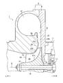
 図1及び図3に示すように、本発明の実施形態に係る遠心圧縮機1は、過給機3に用いられ、遠心力を利用して空気を圧縮するものである。 As shown in FIG.1 and FIG.3, the centrifugal compressor 1 which concerns on embodiment of this invention is used for the supercharger 3, and compresses air using a centrifugal force.
 遠心圧縮機1は、ハウジング(コンプレッサハウジング)5を具備している。ハウジング5は、内側にシュラウド7sを有したハウジング本体7と、このハウジング本体7の右側に設けられたシールプレート9とを備えている。なお、シールプレート9は、過給機3における別のハウジング(軸受ハウジング)11に一体的に連結されている。 The centrifugal compressor 1 includes a housing (compressor housing) 5. The housing 5 includes a housing body 7 having a shroud 7 s inside, and a seal plate 9 provided on the right side of the housing body 7. The seal plate 9 is integrally connected to another housing (bearing housing) 11 in the turbocharger 3.
 ハウジング5内には、インペラ(コンプレッサインペラ)13がその軸心C周りに回転可能に設けられている。インペラ13は、回転軸19の左端部に一体的に連結されている。回転軸19は、別のハウジング11に複数のスラスト軸受15及び複数(1つのみ図示)のラジアル軸受17を介して回転可能に設けられている。また、インペラ13は、ディスク21を備えている。ディスク21はハブ面21hを有する。ハブ面21hは、左方向(インペラ13の軸方向一方側)からの径方向(インペラ13の径方向)外側へ延びている。更に、ディスク21のハブ面21hには、同じ軸長の複数のブレード23が周方向に間隔を置いて一体形成されている。各ブレード23の先端縁23tは、ハウジング本体7のシュラウド7sに沿うように延びている。なお、軸長の同じ複数のブレード23を用いる代わりに、異なる軸長の複数種のブレード(図示省略)を用いてもよい。 In the housing 5, an impeller (compressor impeller) 13 is rotatably provided about its axis C. The impeller 13 is integrally connected to the left end of the rotating shaft 19. The rotating shaft 19 is rotatably provided in another housing 11 via a plurality of thrust bearings 15 and a plurality (only one is shown) of radial bearings 17. The impeller 13 also includes a disk 21. The disk 21 has a hub surface 21 h. The hub surface 21 h extends outward in the radial direction (radial direction of the impeller 13) from the left direction (one side in the axial direction of the impeller 13). Further, a plurality of blades 23 having the same axial length are integrally formed on the hub surface 21 h of the disk 21 at intervals in the circumferential direction. The leading edge 23 t of each blade 23 extends along the shroud 7 s of the housing body 7. Note that, instead of using a plurality of blades 23 having the same axial length, a plurality of blades (not shown) having different axial lengths may be used.
 ハウジング本体7におけるインペラ13の入口側には、導入口(導入流路)25が形成されている。導入口25は、空気をハウジング5内に導入する。また、導入口25は、空気を浄化するエアクリーナ(図示省略)に接続する。ハウジング5内におけるインペラ13の出口側には、ディフューザ(ディフューザ流路)27が形成されている。ディフューザ27は、圧縮した空気(圧縮空気)を減速させて昇圧する。ディフューザ27は例えば環状に形成されている。ハウジング5内におけるインペラ13とディフューザ27との間には、絞り部(絞り流路)29が形成されている。絞り部29の流路幅は、主流の流れ方向に沿って漸次小さくなっている。絞り部29は、例えば環状に形成されている。絞り部29は、ディフューザ27に連通している。 An inlet (introduction channel) 25 is formed on the inlet side of the impeller 13 in the housing body 7. The inlet 25 introduces air into the housing 5. Further, the inlet 25 is connected to an air cleaner (not shown) for purifying the air. A diffuser (diffuser channel) 27 is formed on the outlet side of the impeller 13 in the housing 5. The diffuser 27 decelerates and boosts the compressed air (compressed air). The diffuser 27 is formed, for example, in an annular shape. A throttle portion (throttling channel) 29 is formed between the impeller 13 and the diffuser 27 in the housing 5. The flow passage width of the throttling portion 29 gradually decreases along the main flow direction. The throttling portion 29 is formed, for example, in an annular shape. The throttling portion 29 communicates with the diffuser 27.
 ハウジング5内におけるディフューザ27の出口側には、スクロール(スクロール流路)31が形成されている。スクロール31は渦巻き状に形成されている。スクロール31は、ディフューザ27に連通している。スクロール31の断面積は、巻き終わり側(下流側)が巻き始め側(上流側)よりも大きくなっている。ハウジング本体7の適宜位置には、吐出口(吐出流路)33が形成されている。吐出口33は、圧縮された空気をハウジング5の外側へ吐出する。吐出口33は、スクロール31に連通し、かつエンジンの吸気マニホールドあるいはインタークーラーなどエンジン側吸気配管(図示省略)に接続する。 A scroll (scroll flow path) 31 is formed on the outlet side of the diffuser 27 in the housing 5. The scroll 31 is formed in a spiral shape. The scroll 31 is in communication with the diffuser 27. The cross-sectional area of the scroll 31 is larger at the winding end side (downstream side) than at the winding start side (upstream side). A discharge port (discharge flow path) 33 is formed at an appropriate position of the housing body 7. The discharge port 33 discharges the compressed air to the outside of the housing 5. The discharge port 33 communicates with the scroll 31 and is connected to an engine-side intake pipe (not shown) such as an intake manifold or an intercooler of the engine.
 図1及び図2(a)に示すように、ディフューザ27のシュラウド側壁面27s及びハブ側壁面27hは、径方向(インペラ13の径方向)に延在して設けられる。例えば、径方向に対してそれぞれ平行にすることができる。なお、シュラウド側壁面27sとは、ハウジング本体7のシュラウド7sを径方向外側へ延長した面側に位置する壁面のことをいう。ハブ側壁面27hとは、ディスク21のハブ面21hを径方向外側へ延長した面側に位置する壁面のことをいう。ここで、上述の平行は、厳密である必要はない。即ち、シュラウド側壁面27s及びハブ側壁面27hは、径方向に対して数度程度の角度で傾斜していてもよい。 As shown in FIGS. 1 and 2A, the shroud side wall surface 27s and the hub side wall surface 27h of the diffuser 27 are provided to extend in the radial direction (the radial direction of the impeller 13). For example, they may be parallel to the radial direction. The shroud side wall surface 27s refers to a wall surface located on the radially outer side of the shroud 7s of the housing body 7. As shown in FIG. The hub side wall surface 27 h refers to a wall surface located on the side where the hub surface 21 h of the disk 21 extends radially outward. Here, the above-mentioned parallelism does not have to be exact. That is, the shroud side wall surface 27s and the hub side wall surface 27h may be inclined at an angle of several degrees with respect to the radial direction.
 ディフューザ27のシュラウド側壁面27sの中間部(ディフューザ27の入口27iと出口27oの間)には、複数の環状の段差部35が形成されている。各段差部35は、ディフューザ27の流路幅を主流の流れ方向に沿って広げるように形成されている。各段差部35は、剥離渦を局所的に発生させる。各段差部35は、ディフューザ27の流路幅方向(左右方向)に対して平行である。ただし、図2(b)に示すように、ディフューザ27の流路幅方向に対して直線状又は曲線状に傾斜してもよい。更に、図2(c)に示すように、段差部35の個数を単数(1つ)にしてもよい。ここで、上述の平行は、厳密である必要ではない。 A plurality of annular step portions 35 are formed in the middle of the shroud side wall surface 27s of the diffuser 27 (between the inlet 27i and the outlet 27o of the diffuser 27). Each step 35 is formed to extend the flow passage width of the diffuser 27 along the main flow direction. Each step 35 locally generates a separation vortex. Each stepped portion 35 is parallel to the flow passage width direction (left and right direction) of the diffuser 27. However, as shown to FIG. 2B, you may incline in linear or curvilinear form with respect to the flow-path width direction of the diffuser 27. As shown in FIG. Furthermore, as shown in FIG. 2C, the number of step portions 35 may be single (one). Here, the above-mentioned parallelism does not have to be exact.
 段差部35は連続した環状である必要はない。例えば、段差部35は、スクロール巻き終わり側の舌部近傍など、特定の周方向の領域にのみに設けてもよい。ただし、段差部35を環状に形成する場合は、機械加工が容易となる。 The step 35 need not be a continuous ring. For example, the stepped portion 35 may be provided only in a specific circumferential direction area, such as near the tongue portion on the scroll winding end side. However, when the step portion 35 is formed in an annular shape, machining becomes easy.
 段差部35の個数は、エンジン仕様に合わせて、任意に選択できる。ただし、例えば、段差部35を単数にすることで、特定の作動領域において、ピンポイントに効果を発揮でき、複数の段差部35を設けることで、単数と比較的して広範囲の作動領域において、効果を発揮することができる。ここで、複数の段差部35を設ける一例として、2つの段差部35を設けることができる。2つの段差部35を設けることにより、段差部の加工作業にかかる手間を極力抑えて、単数として比較して広範囲に効果を発揮することができる。 The number of stepped portions 35 can be arbitrarily selected in accordance with engine specifications. However, for example, a single step portion 35 can exert effects on pinpoints in a specific operation region, and by providing a plurality of step portions 35, a single operation in a relatively wide range of operation region, It can be effective. Here, two stepped portions 35 can be provided as an example in which a plurality of stepped portions 35 are provided. By providing the two step portions 35, it is possible to minimize the time and effort required for processing the step portions, and to exhibit the effect in a wide range as compared with a single step.
 段差部35の段差量δは、ディフューザ27の出口27oの流路幅αの5~30%、好ましくは10~20%(0.05~0.30倍、好ましくは、0.10~0.20倍)に設定されている。段差量δを流路幅αの5%以上に設定されるようにしたのは、5%未満であると、段差部35近傍に十分な強度(渦度)の剥離渦を局所的に発生させることが困難になるおそれがあるからである。一方、段差量δを流路幅αの30%未満に設定したのは、30%を超えると、段差部35によって発生した剥離渦(剥離)が増大するおそれがあるからである。 The step amount δ of the step portion 35 is 5 to 30%, preferably 10 to 20% (0.05 to 0.30 times, preferably 0.10 to 0.3) of the flow path width α of the outlet 27 o of the diffuser 27. It is set to 20 times). If the step amount δ is set to 5% or more of the flow path width α, if it is less than 5%, a peeling vortex with sufficient strength (vortex) near the step portion 35 is locally generated. Because it may be difficult. On the other hand, the step amount δ is set to less than 30% of the flow channel width α because if it exceeds 30%, there is a possibility that the peeling vortices (peeling) generated by the step portion 35 may increase.
 ディフューザ27のシュラウド側壁面27sは、段差部35の径方向外側に連続(隣接)する部分を有する。この部分の径方向の長さβは、段差部35の段差量δの5~30倍、好ましくは10~20倍に設定されている。長さβを段差量δの5倍以上に設定されるようにしたのは、5倍未満であると、ディフューザ27の出口27oの手前側において主流の流れをディフューザ27のシュラウド側壁面27sに沿わせることが困難になるおそれがあるからである。一方、長さβを段差部35の30倍以下に設定したのは、30倍を超えると、ディフューザ27のシュラウド側壁面27sにおけるディフューザ27の出口27oの手前側に新たな流れの剥離渦(剥離)が発生して、ディフューザ27内の有効流路面積が減少するおそれがあるからである。 The shroud side wall surface 27 s of the diffuser 27 has a portion that is continuous (adjacent) to the radially outer side of the stepped portion 35. The radial length β of this portion is set to 5 to 30 times, preferably 10 to 20 times, the step amount δ of the step portion 35. If the length β is set to five times or more of the step amount δ, it is less than five times that the main flow along the shroud sidewall surface 27s of the diffuser 27 on the front side of the outlet 27o of the diffuser 27 It may be difficult to On the other hand, when the length β is set to 30 times or less of the step portion 35, if it exceeds 30 times, a new flow of separation vortex (peeling off the front side of the outlet 27o of the diffuser 27 on the shroud side wall surface 27s of the diffuser 27) ), And the effective flow area in the diffuser 27 may be reduced.
 続いて、本発明の実施形態の作用及び効果について説明する。 Subsequently, the operation and effects of the embodiment of the present invention will be described.
 過給機3におけるラジアルタービン(図示省略)の駆動によりインペラ13をその軸心周りに回転軸19と一体的に回転させることにより、導入口25からハウジング5内に導入した空気を圧縮することができる。そして、圧縮した空気(圧縮空気)は、ディフューザ27によって減速させながら昇圧され、スクロール31を経由して吐出口33からハウジング5の外側へ吐出される。 Air introduced into the housing 5 from the inlet 25 can be compressed by rotating the impeller 13 integrally with the rotation shaft 19 around its axis by driving of a radial turbine (not shown) in the turbocharger 3. it can. Then, the compressed air (compressed air) is boosted while being decelerated by the diffuser 27, and is discharged to the outside of the housing 5 from the discharge port 33 via the scroll 31.
 ディフューザ27のシュラウド側壁面27s及びハブ側壁面27hは、径方向に対してそれぞれ平行である。また、ディフューザ27のシュラウド側壁面27sの中間部に、環状の段差部35がディフューザ27の流路幅を主流の流れ方向に沿って広げるように形成されている。そのため、前述の新規な知見を適用すると、遠心圧縮機1の運転(過給機3の運転)中に、シュラウド側壁面27sにおけるディフューザ27の出口27o側での流れの剥離(剥離渦)の発達が抑えられ、その剥離による低圧部(ブロッケージ、低圧領域、閉塞領域)を縮小することができる。 The shroud side wall surface 27s and the hub side wall surface 27h of the diffuser 27 are respectively parallel to the radial direction. Further, an annular step portion 35 is formed at an intermediate portion of the shroud side wall surface 27s of the diffuser 27 so as to expand the flow passage width of the diffuser 27 along the main flow direction. Therefore, applying the above-mentioned new findings, during the operation of the centrifugal compressor 1 (the operation of the supercharger 3), the development of flow separation (a separation vortex) at the outlet 27o side of the diffuser 27 in the shroud side wall surface 27s. Can be reduced, and the low pressure part (blockage, low pressure area, closed area) due to the exfoliation can be reduced.
 従って、本発明の実施形態によれば、遠心圧縮機1の運転中に、シュラウド側壁面27sにおけるディフューザ27の出口27o側の流れの剥離の発達を抑えることができる。そのため、ディフューザ27の出口27o側の有効流路面積の減少が抑えられる。従って、ディフューザ27によって主流の流れを十分に減速させることができる。また、遠心圧縮機1の運転中に、シュラウド側壁面27sにおけるディフューザ27の出口27o側の流れの剥離による低圧部LPを縮小できる。そのため、その低圧部LPとスクロール31内の主流の流れとの衝突(干渉)を緩和して、スクロール31の下流側に位置する吐出口33内における主流の流れに乱れが生じることを抑えることができる。よって、本発明の実施形態によれば、ディフューザ27の静圧回復性能を高めつつ、遠心圧縮機1の圧縮機効率の向上を図ることができる。 Therefore, according to the embodiment of the present invention, it is possible to suppress the development of flow separation on the outlet side 27 o of the diffuser 27 at the shroud side wall surface 27 s during operation of the centrifugal compressor 1. Therefore, the reduction of the effective flow passage area on the outlet 27o side of the diffuser 27 can be suppressed. Therefore, the main flow can be sufficiently decelerated by the diffuser 27. In addition, during operation of the centrifugal compressor 1, the low pressure portion LP can be reduced due to flow separation on the outlet 27o side of the diffuser 27 at the shroud side wall surface 27s. Therefore, the collision (interference) between the low pressure portion LP and the main flow in the scroll 31 is alleviated, and the occurrence of disturbance in the main flow in the discharge port 33 located on the downstream side of the scroll 31 can be suppressed. it can. Therefore, according to the embodiment of the present invention, the compressor efficiency of the centrifugal compressor 1 can be improved while improving the static pressure recovery performance of the diffuser 27.
 なお、本発明は、前述の実施形態の説明に限るものでなく、例えば遠心圧縮機1に適用した技術的思想をガスタービン、産業用空気設備等に適用したり、ディフューザ27に複数のディフューザベーン(図示省略)を周方向に間隔を置いて配設したりする等、その他、種々の態様で実施可能である。また、本発明に包含される権利範囲は、これらの実施形態に限定されないものである。 The present invention is not limited to the description of the above-described embodiment. For example, the technical idea applied to the centrifugal compressor 1 may be applied to a gas turbine, an industrial air facility, etc. The present invention can be implemented in various other manners, such as disposing (not shown) at intervals in the circumferential direction. Further, the scope of rights included in the present invention is not limited to these embodiments.
 本発明の実施例について図6(a)、図6(b)及び図7を参照して説明する。 Embodiments of the present invention will be described with reference to FIGS. 6 (a), 6 (b) and 7. FIG.
 発明例(図4(a)参照)及び比較例(図4(b)参照)に対し、圧縮機効率のピーク付近の作動域におけるスクロール内及びディフューザ内の静圧分布について数値流体解析を行った。その結果、図6(a)に示す発明例の方が、図6(b)に示す比較例に比べてスクロール内の静圧を全体的に高くできることが確認できた。換言すれば、ディフューザの静圧回復性能を高くできることが確認できた。また、図示は省略するが、圧縮機効率のピーク付近の作動域だけでなく、小流量側及び大流量側の作動域においても、同様の解析結果を得ることができた。なお、図6(a)及び図6(b)中の数値は、スクロール内の静圧を無次元化したものである。 In the invention examples (see FIG. 4 (a)) and the comparative example (see FIG. 4 (b)), numerical fluid analysis was performed on static pressure distributions in the scroll and the diffuser in the working area near the compressor efficiency peak . As a result, it was confirmed that the static pressure in the scroll can be generally increased in the invention example shown in FIG. 6 (a) as compared with the comparative example shown in FIG. 6 (b). In other words, it has been confirmed that the static pressure recovery performance of the diffuser can be enhanced. Although not shown, similar analysis results could be obtained not only in the working area near the peak of the compressor efficiency but also in the working area on the small flow side and the large flow side. The numerical values in FIGS. 6 (a) and 6 (b) are obtained by making the static pressure in the scroll non-dimensional.
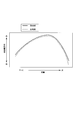
 また、発明例(図4(a)参照)及び比較例(図4(b)参照)における流量と圧縮機効率との関係について数値流体解析を行った。その結果、図7に示すように、発明例の方が比較例に比べて小流量側から大流量側の広い作動域において圧縮機効率を向上させることが確認された。 In addition, numerical fluid analysis was performed on the relationship between the flow rate and the compressor efficiency in the invention example (see FIG. 4A) and the comparative example (see FIG. 4B). As a result, as shown in FIG. 7, it was confirmed that the invention example improves the compressor efficiency in a wide operation area from the small flow rate side to the large flow rate side as compared with the comparative example.

Claims (6)

  1.  遠心力を利用して流体を圧縮する遠心圧縮機であって、
     内側にシュラウドを有したハウジングと、
     前記ハウジング内に回転可能に設けられたインペラと、
     前記ハウジング内における前記インペラの出口側の径方向外側に形成されたディフューザと、
     前記ハウジング内における前記ディフューザの出口側に形成されたスクロールと
    を具備し、
     前記ディフューザのシュラウド側壁面及びハブ側壁面は、径方向にそれぞれ延在し、
     前記ディフューザのシュラウド側壁面に、少なくとも1つの段差部が、前記ディフューザの流路幅を主流の流れ方向に沿って広げるように形成されていることを特徴とする遠心圧縮機。
    A centrifugal compressor that compresses fluid using centrifugal force, and
    A housing with a shroud inside;
    An impeller rotatably provided in the housing;
    A diffuser formed radially outward on the outlet side of the impeller in the housing;
    And a scroll formed on the outlet side of the diffuser within the housing,
    The shroud side wall surface and the hub side wall surface of the diffuser respectively extend in the radial direction;
    At least one level | step-difference part is formed in the shroud side wall surface of the said diffuser so that the flow-path width | variety of the said diffuser may be extended along the mainstream flow direction, The centrifugal compressor characterized by the above-mentioned.
  2.  前記段差部の段差量が前記ディフューザの出口の流路幅の5~30%に設定されていることを特徴とする請求項1に記載の遠心圧縮機。 The centrifugal compressor according to claim 1, wherein the step amount of the step portion is set to 5 to 30% of the flow passage width of the outlet of the diffuser.
  3.  前記ディフューザのシュラウド側壁面における前記段差部の径方向外側に連続する部分の径方向長さが前記段差部の段差量の5~30倍に設定されていることを特徴とする請求項1に記載の遠心圧縮機。 The radial direction length of the part which follows the radial direction outside of the above-mentioned level difference part in the shroud side wall surface of the above-mentioned diffuser is set up 5 to 30 times the amount of level differences of the above-mentioned level difference part. Centrifugal compressor.
  4.  前記ディフューザのシュラウド側壁面における前記段差部の径方向外側に連続する部分の径方向長さが前記段差部の段差量の5~30倍に設定されていることを特徴とする請求項2に記載の遠心圧縮機。 The radial direction length of the part which follows the radial direction outside of the above-mentioned level difference part in the shroud side wall surface of the above-mentioned diffuser is set up 5 to 30 times the amount of level differences of the above-mentioned level difference part. Centrifugal compressor.
  5.  前記段差部は環状に形成されていることを特徴とする請求項1から請求項4のうちのいずれか1項に記載の遠心圧縮機。 The said level | step-difference part is cyclically | annularly formed, The centrifugal compressor of any one of the Claims 1-4 characterized by the above-mentioned.
  6.  請求項1から請求項5のうちのいずれか1項に記載の遠心圧縮機を具備したことを特徴とする過給機。
     
    A turbocharger comprising the centrifugal compressor according to any one of claims 1 to 5.
PCT/JP2014/069936 2013-08-06 2014-07-29 Centrifugal compressor and supercharger WO2015019901A1 (en)

Priority Applications (4)

Application Number Priority Date Filing Date Title
JP2015530830A JP6323454B2 (en) 2013-08-06 2014-07-29 Centrifugal compressor and turbocharger
EP14834428.6A EP3032108B8 (en) 2013-08-06 2014-07-29 Centrifugal compressor and turbocharger
CN201480032889.XA CN105339675A (en) 2013-08-06 2014-07-29 Centrifugal compressor and supercharger
US14/950,094 US10066638B2 (en) 2013-08-06 2015-11-24 Centrifugal compressor and turbocharger

Applications Claiming Priority (2)

Application Number Priority Date Filing Date Title
JP2013162984 2013-08-06
JP2013-162984 2013-08-06

Related Child Applications (1)

Application Number Title Priority Date Filing Date
US14/950,094 Continuation US10066638B2 (en) 2013-08-06 2015-11-24 Centrifugal compressor and turbocharger

Publications (1)

Publication Number Publication Date
WO2015019901A1 true WO2015019901A1 (en) 2015-02-12

Family

ID=52461239

Family Applications (1)

Application Number Title Priority Date Filing Date
PCT/JP2014/069936 WO2015019901A1 (en) 2013-08-06 2014-07-29 Centrifugal compressor and supercharger

Country Status (5)

Country Link
US (1) US10066638B2 (en)
EP (1) EP3032108B8 (en)
JP (1) JP6323454B2 (en)
CN (1) CN105339675A (en)
WO (1) WO2015019901A1 (en)

Cited By (5)

* Cited by examiner, † Cited by third party
Publication number Priority date Publication date Assignee Title
CN104819166A (en) * 2015-05-11 2015-08-05 山东赛马力发电设备有限公司 Device and method for reducing oil leakage of supercharger compressor
CN106837858A (en) * 2017-01-05 2017-06-13 上海交通大学 Sawtooth reducing-flow structure
WO2017140852A1 (en) * 2016-02-19 2017-08-24 Abb Turbo Systems Ag Diffuser of a radial-flow compressor
CN107614886A (en) * 2015-10-29 2018-01-19 三菱重工业株式会社 Volute and centrifugal compressor
JP2020511609A (en) * 2017-03-08 2020-04-16 ロベルト・ボッシュ・ゲゼルシャフト・ミト・ベシュレンクテル・ハフツングRobert Bosch Gmbh Centrifugal turbo compressor

Families Citing this family (17)

* Cited by examiner, † Cited by third party
Publication number Priority date Publication date Assignee Title
KR102104415B1 (en) * 2015-02-05 2020-04-24 한화파워시스템 주식회사 Compressor
GB2551804B (en) * 2016-06-30 2021-04-07 Cummins Ltd Diffuser for a centrifugal compressor
CN106640754B (en) * 2017-01-05 2020-06-12 上海交通大学 Novel centrifugal compressor with annular protrusion structure
CN107061356B (en) * 2017-01-05 2020-01-07 上海交通大学 Groove flow choking structure
JP6908472B2 (en) * 2017-08-31 2021-07-28 三菱重工コンプレッサ株式会社 Centrifugal compressor
EP3460256A1 (en) * 2017-09-20 2019-03-27 Siemens Aktiengesellschaft Throughflow assembly
EP3460257A1 (en) * 2017-09-20 2019-03-27 Siemens Aktiengesellschaft Throughflow assembly
DE102017127758A1 (en) * 2017-11-24 2019-05-29 Man Diesel & Turbo Se Centrifugal compressor and turbocharger
DE102018115446A1 (en) * 2018-06-27 2020-01-02 Ihi Charging Systems International Gmbh turbocharger
US10935045B2 (en) * 2018-07-19 2021-03-02 GM Global Technology Operations LLC Centrifugal compressor with inclined diffuser
JP6950831B2 (en) * 2018-08-23 2021-10-13 株式会社Ihi Centrifugal compressor
DE102018215888A1 (en) * 2018-09-19 2020-03-19 Robert Bosch Gmbh compressor
US11131236B2 (en) * 2019-03-13 2021-09-28 Garrett Transportation I Inc. Turbocharger having adjustable-trim centrifugal compressor including divergent-wall diffuser
CN111120400A (en) * 2019-12-24 2020-05-08 哈尔滨工程大学 Centrifugal compressor for micro gas turbine
CN112879349B (en) * 2021-01-15 2022-04-19 宁波方太厨具有限公司 Air inlet device, fan system with air inlet device and cleaning machine
US20230093314A1 (en) * 2021-09-17 2023-03-23 Carrier Corporation Passive flow reversal reduction in compressor assembly
US11788557B1 (en) * 2022-05-06 2023-10-17 Ingersoll-Rand Industrial U.S., Inc. Centrifugal acceleration stabilizer

Citations (15)

* Cited by examiner, † Cited by third party
Publication number Priority date Publication date Assignee Title
JPS6070798U (en) * 1983-10-24 1985-05-18 三菱重工業株式会社 centrifugal fluid machine
JPS6184199U (en) * 1984-11-08 1986-06-03
JPS62188598U (en) * 1986-05-23 1987-12-01
JPH0212097U (en) * 1988-07-08 1990-01-25
JPH078597U (en) * 1993-07-06 1995-02-07 三菱重工業株式会社 Centrifugal compressor
JPH10176699A (en) * 1996-12-18 1998-06-30 Ishikawajima Harima Heavy Ind Co Ltd Centrifugal compressor
JP2006220053A (en) 2005-02-10 2006-08-24 Mitsubishi Heavy Ind Ltd Scroll structure for variable displacement exhaust turbocharger and method for manufacturing the same
JP2008510100A (en) * 2004-08-19 2008-04-03 ハネウェル・インターナショナル・インコーポレーテッド Compressor wheel housing
JP2008163821A (en) * 2006-12-28 2008-07-17 Toyota Central R&D Labs Inc Centrifugal compressor
JP2009002305A (en) 2007-06-25 2009-01-08 Toyota Motor Corp Supercharger
JP2010196542A (en) 2009-02-24 2010-09-09 Toyota Motor Corp Centrifugal compressor, and turbosupercharger
JP2012041844A (en) * 2010-08-17 2012-03-01 Toyota Motor Corp Centrifugal compressor apparatus
JP2013204550A (en) * 2012-03-29 2013-10-07 Mitsubishi Heavy Ind Ltd Centrifugal compressor
JP2014074390A (en) * 2012-10-05 2014-04-24 Ihi Corp Centrifugal compressor
JP2014074389A (en) * 2012-10-05 2014-04-24 Ihi Corp Centrifugal compressor

Family Cites Families (9)

* Cited by examiner, † Cited by third party
Publication number Priority date Publication date Assignee Title
US4181466A (en) * 1977-03-17 1980-01-01 Wallace Murray Corp. Centrifugal compressor and cover
US4251183A (en) * 1978-01-30 1981-02-17 The Garrett Corp. Crossover duct assembly
US4378194A (en) * 1980-10-02 1983-03-29 Carrier Corporation Centrifugal compressor
JPS58183899A (en) 1982-04-21 1983-10-27 Hitachi Ltd Diffuser with blade
JP3153409B2 (en) * 1994-03-18 2001-04-09 株式会社日立製作所 Manufacturing method of centrifugal compressor
JP2005240681A (en) 2004-02-26 2005-09-08 Mitsubishi Heavy Ind Ltd Axial flow fan
DE102008036633B4 (en) * 2008-08-06 2019-06-19 Continental Mechanical Components Germany Gmbh Turbocharger with an insert plate
FR2942267B1 (en) * 2009-02-19 2011-05-06 Turbomeca EROSION LAMP FOR COMPRESSOR WHEEL
JP5535562B2 (en) 2009-09-16 2014-07-02 三菱重工業株式会社 Discharge scroll and turbo machine

Patent Citations (15)

* Cited by examiner, † Cited by third party
Publication number Priority date Publication date Assignee Title
JPS6070798U (en) * 1983-10-24 1985-05-18 三菱重工業株式会社 centrifugal fluid machine
JPS6184199U (en) * 1984-11-08 1986-06-03
JPS62188598U (en) * 1986-05-23 1987-12-01
JPH0212097U (en) * 1988-07-08 1990-01-25
JPH078597U (en) * 1993-07-06 1995-02-07 三菱重工業株式会社 Centrifugal compressor
JPH10176699A (en) * 1996-12-18 1998-06-30 Ishikawajima Harima Heavy Ind Co Ltd Centrifugal compressor
JP2008510100A (en) * 2004-08-19 2008-04-03 ハネウェル・インターナショナル・インコーポレーテッド Compressor wheel housing
JP2006220053A (en) 2005-02-10 2006-08-24 Mitsubishi Heavy Ind Ltd Scroll structure for variable displacement exhaust turbocharger and method for manufacturing the same
JP2008163821A (en) * 2006-12-28 2008-07-17 Toyota Central R&D Labs Inc Centrifugal compressor
JP2009002305A (en) 2007-06-25 2009-01-08 Toyota Motor Corp Supercharger
JP2010196542A (en) 2009-02-24 2010-09-09 Toyota Motor Corp Centrifugal compressor, and turbosupercharger
JP2012041844A (en) * 2010-08-17 2012-03-01 Toyota Motor Corp Centrifugal compressor apparatus
JP2013204550A (en) * 2012-03-29 2013-10-07 Mitsubishi Heavy Ind Ltd Centrifugal compressor
JP2014074390A (en) * 2012-10-05 2014-04-24 Ihi Corp Centrifugal compressor
JP2014074389A (en) * 2012-10-05 2014-04-24 Ihi Corp Centrifugal compressor

Non-Patent Citations (1)

* Cited by examiner, † Cited by third party
Title
See also references of EP3032108A4 *

Cited By (11)

* Cited by examiner, † Cited by third party
Publication number Priority date Publication date Assignee Title
CN104819166A (en) * 2015-05-11 2015-08-05 山东赛马力发电设备有限公司 Device and method for reducing oil leakage of supercharger compressor
CN107614886A (en) * 2015-10-29 2018-01-19 三菱重工业株式会社 Volute and centrifugal compressor
EP3299635A4 (en) * 2015-10-29 2018-05-30 Mitsubishi Heavy Industries, Ltd. Scroll casing and centrifugal compressor
US11078922B2 (en) 2015-10-29 2021-08-03 Mitsubishi Heavy Industries Engine & Turbocharger, Ltd. Scroll casing and centrifugal compressor
WO2017140852A1 (en) * 2016-02-19 2017-08-24 Abb Turbo Systems Ag Diffuser of a radial-flow compressor
CN109072939A (en) * 2016-02-19 2018-12-21 Abb涡轮系统有限公司 The diffuser of radial flow compressor
CN106837858A (en) * 2017-01-05 2017-06-13 上海交通大学 Sawtooth reducing-flow structure
CN106837858B (en) * 2017-01-05 2020-01-07 上海交通大学 Sawtooth choked flow structure
JP2020511609A (en) * 2017-03-08 2020-04-16 ロベルト・ボッシュ・ゲゼルシャフト・ミト・ベシュレンクテル・ハフツングRobert Bosch Gmbh Centrifugal turbo compressor
US11242857B2 (en) 2017-03-08 2022-02-08 Robert Bosch Gmbh Centrifugal turbo-compressor
JP7110219B2 (en) 2017-03-08 2022-08-01 ロベルト・ボッシュ・ゲゼルシャフト・ミト・ベシュレンクテル・ハフツング centrifugal turbo compressor

Also Published As

Publication number Publication date
EP3032108A1 (en) 2016-06-15
EP3032108B8 (en) 2020-06-17
JPWO2015019901A1 (en) 2017-03-02
JP6323454B2 (en) 2018-05-16
US10066638B2 (en) 2018-09-04
EP3032108A4 (en) 2017-03-29
US20160076553A1 (en) 2016-03-17
EP3032108B1 (en) 2020-02-19
CN105339675A (en) 2016-02-17

Similar Documents

Publication Publication Date Title
WO2015019901A1 (en) Centrifugal compressor and supercharger
US7575412B2 (en) Anti-stall casing treatment for turbo compressors
CA2496543C (en) Recirculation structure for a turbocompressor
EP2803866B1 (en) Centrifugal compressor with casing treatment for surge control
US10330102B2 (en) Centrifugal compressor and turbocharger
US20120100003A1 (en) Impeller and rotary machine
JP6112223B2 (en) Centrifugal compressor and turbocharger
WO2016024461A1 (en) Compressor stator vane, axial flow compressor, and gas turbine
US10138898B2 (en) Centrifugal compressor and turbocharger
WO2018181343A1 (en) Centrifugal compressor
WO2014087690A1 (en) Centrifugal compressor
US20130280053A1 (en) Axial compressor
US10221858B2 (en) Impeller blade morphology
JP2010144698A (en) Centrifugal compressor
JP2009197613A (en) Centrifugal compressor and diffuser vane unit
JP5251587B2 (en) Centrifugal compressor
WO2018155546A1 (en) Centrifugal compressor
US20120121404A1 (en) Exhaust Hood Diffuser
JP2018178769A (en) Multistage fluid machine
JP2015190382A (en) compressor impeller, centrifugal compressor, and supercharger
JP6349645B2 (en) Centrifugal compressor and multistage compressor
CN110234888A (en) The swirl shape and booster of compressor
JP2012177357A (en) Radial turbine and supercharger
JP2015040505A (en) Centrifugal compressor and supercharger
JP5428962B2 (en) Axial compressor and gas turbine engine

Legal Events

Date Code Title Description
WWE Wipo information: entry into national phase

Ref document number: 201480032889.X

Country of ref document: CN

121 Ep: the epo has been informed by wipo that ep was designated in this application

Ref document number: 14834428

Country of ref document: EP

Kind code of ref document: A1

ENP Entry into the national phase

Ref document number: 2015530830

Country of ref document: JP

Kind code of ref document: A

WWE Wipo information: entry into national phase

Ref document number: 2014834428

Country of ref document: EP

NENP Non-entry into the national phase

Ref country code: DE