JP6908472B2 - Centrifugal compressor - Google Patents
Centrifugal compressor Download PDFInfo
- Publication number
- JP6908472B2 JP6908472B2 JP2017167059A JP2017167059A JP6908472B2 JP 6908472 B2 JP6908472 B2 JP 6908472B2 JP 2017167059 A JP2017167059 A JP 2017167059A JP 2017167059 A JP2017167059 A JP 2017167059A JP 6908472 B2 JP6908472 B2 JP 6908472B2
- Authority
- JP
- Japan
- Prior art keywords
- inner peripheral
- diaphragm
- peripheral surface
- scroll
- casing
- Prior art date
- Legal status (The legal status is an assumption and is not a legal conclusion. Google has not performed a legal analysis and makes no representation as to the accuracy of the status listed.)
- Expired - Fee Related
Links
Images


Classifications
-
- F—MECHANICAL ENGINEERING; LIGHTING; HEATING; WEAPONS; BLASTING
- F04—POSITIVE - DISPLACEMENT MACHINES FOR LIQUIDS; PUMPS FOR LIQUIDS OR ELASTIC FLUIDS
- F04D—NON-POSITIVE-DISPLACEMENT PUMPS
- F04D29/00—Details, component parts, or accessories
- F04D29/40—Casings; Connections of working fluid
- F04D29/42—Casings; Connections of working fluid for radial or helico-centrifugal pumps
- F04D29/44—Fluid-guiding means, e.g. diffusers
- F04D29/441—Fluid-guiding means, e.g. diffusers especially adapted for elastic fluid pumps
-
- F—MECHANICAL ENGINEERING; LIGHTING; HEATING; WEAPONS; BLASTING
- F04—POSITIVE - DISPLACEMENT MACHINES FOR LIQUIDS; PUMPS FOR LIQUIDS OR ELASTIC FLUIDS
- F04D—NON-POSITIVE-DISPLACEMENT PUMPS
- F04D1/00—Radial-flow pumps, e.g. centrifugal pumps; Helico-centrifugal pumps
- F04D1/06—Multi-stage pumps
-
- F—MECHANICAL ENGINEERING; LIGHTING; HEATING; WEAPONS; BLASTING
- F04—POSITIVE - DISPLACEMENT MACHINES FOR LIQUIDS; PUMPS FOR LIQUIDS OR ELASTIC FLUIDS
- F04D—NON-POSITIVE-DISPLACEMENT PUMPS
- F04D17/00—Radial-flow pumps, e.g. centrifugal pumps; Helico-centrifugal pumps
- F04D17/08—Centrifugal pumps
- F04D17/10—Centrifugal pumps for compressing or evacuating
- F04D17/12—Multi-stage pumps
- F04D17/122—Multi-stage pumps the individual rotor discs being, one for each stage, on a common shaft and axially spaced, e.g. conventional centrifugal multi- stage compressors
-
- F—MECHANICAL ENGINEERING; LIGHTING; HEATING; WEAPONS; BLASTING
- F04—POSITIVE - DISPLACEMENT MACHINES FOR LIQUIDS; PUMPS FOR LIQUIDS OR ELASTIC FLUIDS
- F04D—NON-POSITIVE-DISPLACEMENT PUMPS
- F04D29/00—Details, component parts, or accessories
- F04D29/26—Rotors specially for elastic fluids
- F04D29/28—Rotors specially for elastic fluids for centrifugal or helico-centrifugal pumps for radial-flow or helico-centrifugal pumps
- F04D29/284—Rotors specially for elastic fluids for centrifugal or helico-centrifugal pumps for radial-flow or helico-centrifugal pumps for compressors
- F04D29/286—Rotors specially for elastic fluids for centrifugal or helico-centrifugal pumps for radial-flow or helico-centrifugal pumps for compressors multi-stage rotors
-
- F—MECHANICAL ENGINEERING; LIGHTING; HEATING; WEAPONS; BLASTING
- F05—INDEXING SCHEMES RELATING TO ENGINES OR PUMPS IN VARIOUS SUBCLASSES OF CLASSES F01-F04
- F05B—INDEXING SCHEME RELATING TO WIND, SPRING, WEIGHT, INERTIA OR LIKE MOTORS, TO MACHINES OR ENGINES FOR LIQUIDS COVERED BY SUBCLASSES F03B, F03D AND F03G
- F05B2240/00—Components
- F05B2240/10—Stators
- F05B2240/12—Fluid guiding means, e.g. vanes
Landscapes
- Engineering & Computer Science (AREA)
- Mechanical Engineering (AREA)
- General Engineering & Computer Science (AREA)
- Structures Of Non-Positive Displacement Pumps (AREA)
Description
本開示は、遠心圧縮機に関する。 The present disclosure relates to a centrifugal compressor.
従来の遠心圧縮機の一例として、特許文献1には、軸方向に配列された複数段のインペラと、インペラの外周側に設けられる複数のダイアフラムと、を含む遠心圧縮機が開示されている。
As an example of a conventional centrifugal compressor,
この種の遠心圧縮機は、吐出口に連通するスクロール流路を有する。スクロール流路は、通常、吐出側のダイアフラムの外周面によってスクロール流路の内周壁が形成される一方、該ダイアフラムおよび該ダイアフラムに対して軸方向の隣に位置するダイアフラムとの間に設けられる環状スペーサの内周面によってスクロール流路の外周壁が形成される。 This type of centrifugal compressor has a scroll flow path that communicates with the discharge port. The scroll flow path is usually an annular shape provided between the diaphragm and a diaphragm located axially adjacent to the diaphragm, while the inner peripheral wall of the scroll flow path is formed by the outer peripheral surface of the diaphragm on the discharge side. The inner peripheral surface of the spacer forms the outer peripheral wall of the scroll flow path.
ところで、圧縮機における損失を低減するためには、スクロール流路における流体損失を低減させることは重要である。
しかしながら、従来の遠心圧縮機のように、一のダイアフラムの表面によってスクロール流路の内周壁を形成する一方、環状スペーサの内周面によってスクロール流路の外周壁を形成する場合、圧縮機の大型化を回避しながらスクロール流路の流路面積を十分に確保することが難しく、スクロール断面流速が増加することにより摩擦損失が比較的大きくなると考えられる。
そこで、遠心圧縮機において、スクロール流路における流体損失をより低減することが求められる。
By the way, in order to reduce the loss in the compressor, it is important to reduce the fluid loss in the scroll flow path.
However, when the inner peripheral wall of the scroll flow path is formed by the surface of one diaphragm as in the conventional centrifugal compressor, and the outer peripheral wall of the scroll flow path is formed by the inner peripheral surface of the annular spacer, the size of the compressor is large. It is difficult to secure a sufficient flow path area of the scroll flow path while avoiding the change, and it is considered that the friction loss becomes relatively large due to the increase in the scroll cross-sectional flow velocity.
Therefore, in a centrifugal compressor, it is required to further reduce the fluid loss in the scroll flow path.
上述の事情に鑑みて、本発明の少なくとも一実施形態は、圧縮機の大型化を避けながらスクロール流路における流体損失を低減可能な遠心圧縮機を提供することを目的とする。 In view of the above circumstances, at least one embodiment of the present invention aims to provide a centrifugal compressor capable of reducing fluid loss in a scroll flow path while avoiding an increase in the size of the compressor.
(1)本発明の少なくとも一実施形態に係る遠心圧縮機は、
軸方向に互いに隣り合う第1ダイアフラム及び第2ダイアフラムを含む複数のダイアフラムと、
前記複数のダイアフラムの外周側に設けられ、前記複数のダイアフラムを含む内部部品を収容するケーシングと、
前記第1ダイアフラムと前記第2ダイアフラムとの間に設けられる少なくとも一つの軸方向スペーサと、
前記第1ダイアフラムの外周面よりも径方向内側に位置する前記第1ダイアフラムの表面によって形成されるスクロール内周壁、および、前記ケーシングの内周面によって少なくとも一部が形成されるスクロール外周壁によって形成されるスクロール流路と、
を備える。
(1) The centrifugal compressor according to at least one embodiment of the present invention is
A plurality of diaphragms including a first diaphragm and a second diaphragm adjacent to each other in the axial direction, and
A casing provided on the outer peripheral side of the plurality of diaphragms and accommodating internal parts including the plurality of diaphragms, and a casing.
At least one axial spacer provided between the first diaphragm and the second diaphragm,
Formed by a scroll inner peripheral wall formed by the surface of the first diaphragm located radially inside the outer peripheral surface of the first diaphragm, and a scroll outer peripheral wall formed by at least a part by the inner peripheral surface of the casing. Scroll flow path and
To be equipped.
上記(1)の構成では、スクロール外周壁の少なくとも一部をケーシングの内周面によって形成するようにしたので、ケーシングを大きくしなくても、スクロール流路面積を拡大してスクロール断面流速を低減し、スクロール流路における摩擦損失を低減することができる。これにより、遠心圧縮機の大型化を抑制しながら、スクロール流路における流体損失を低減することができる。 In the configuration of (1) above, since at least a part of the outer peripheral wall of the scroll is formed by the inner peripheral surface of the casing, the scroll flow path area is expanded and the scroll cross-sectional flow velocity is reduced without increasing the casing. However, the friction loss in the scroll flow path can be reduced. As a result, it is possible to reduce the fluid loss in the scroll flow path while suppressing the increase in size of the centrifugal compressor.
(2)幾つかの実施形態では、上記(1)の構成において、
前記少なくとも一つの軸方向スペーサは、前記ケーシングの前記内周面よりも前記径方向内側において周方向に設けられた複数の軸方向スペーサを含む。
(2) In some embodiments, in the configuration of (1) above,
The at least one axial spacer includes a plurality of axial spacers provided in the circumferential direction inside the inner peripheral surface of the casing in the radial direction.
上記(2)の構成によれば、第1ダイアフラムと第2ダイアフラムとの間に、周方向に複数の軸方向スペーサを設けたので、第2ダイアフラムに対する第1ダイアフラムの軸方向における位置決めを確実に行うことができる。 According to the configuration of (2) above, since a plurality of axial spacers are provided in the circumferential direction between the first diaphragm and the second diaphragm, the axial positioning of the first diaphragm with respect to the second diaphragm is ensured. It can be carried out.
(3)幾つかの実施形態では、上記(2)の構成において、
前記軸方向スペーサの各々は、前記スクロール内周壁に対向するスペーサ内周面を有し、
前記スペーサ内周面は、
前記ケーシングの前記内周面に連なる上流側輪郭部と、
前記上流側輪郭部に対してスクロール流れの下流側に位置し、前記軸方向スペーサのうち最も径方向内側に位置する点において前記上流側輪郭部に接続される下流側輪郭部と、
を含み、
前記スクロール外周壁は、各々の前記軸方向スペーサの前記スペーサ内周面と、前記ケーシングの前記内周面と、によって形成される。
(3) In some embodiments, in the configuration of (2) above,
Each of the axial spacers has a spacer inner peripheral surface facing the scroll inner peripheral wall.
The inner peripheral surface of the spacer is
An upstream contour portion connected to the inner peripheral surface of the casing,
A downstream contour portion connected to the upstream contour portion at a point located on the downstream side of the scroll flow with respect to the upstream contour portion and located on the innermost radial direction of the axial spacers.
Including
The scroll outer peripheral wall is formed by the spacer inner peripheral surface of each of the axial spacers and the inner peripheral surface of the casing.
上記(3)の構成によれば、ケーシングの内周面と、該ケーシングの内周面に連なる上流側輪郭部及び軸方向スペーサのうち最も径方向内側に位置する点において該上流側輪郭部に接続される下流側輪郭部を含むスペーサ内周面と、によりスクロール外周壁が形成される。すなわち、ケーシングの内周面と、軸方向スペーサの内周面とが接続されたスクロール外周壁が形成されるので、ケーシングの内周面と軸方向スペーサの表面とが接続されていない場合に比べて、スクロール流路内における流体流れの乱れを抑制することができる。よって、スクロール流路における流体損失を効果的に低減することができる。 According to the configuration of (3) above, the upstream contour portion is located on the inner peripheral surface of the casing, the upstream contour portion connected to the inner peripheral surface of the casing, and the axially innermost point of the axial spacers. An outer peripheral wall of the scroll is formed by the inner peripheral surface of the spacer including the contour portion on the downstream side to be connected. That is, since the scroll outer peripheral wall in which the inner peripheral surface of the casing and the inner peripheral surface of the axial spacer are connected is formed, compared with the case where the inner peripheral surface of the casing and the surface of the axial spacer are not connected. Therefore, the turbulence of the fluid flow in the scroll flow path can be suppressed. Therefore, the fluid loss in the scroll flow path can be effectively reduced.
(4)幾つかの実施形態では、上記(3)の構成において、
前記上流側輪郭部は、
径方向外側に向かって凸状である第1湾曲面と、
前記第1湾曲面に対して前記スクロール流れの下流側に位置し、径方向内側に向かって凸状である第2湾曲面と、
を含む。
(4) In some embodiments, in the configuration of (3) above,
The upstream contour portion is
A first curved surface that is convex outward in the radial direction,
A second curved surface located on the downstream side of the scroll flow with respect to the first curved surface and convex inward in the radial direction.
including.
上記(4)の構成によれば、スクロール外周壁を形成する上流側輪郭部は、径方向外側に向かって凸状である第1湾曲面と、該第1湾曲面に対してスクロール流れの下流側に位置し、径方向内側に向かって凸状である第2湾曲面とを含む。よって、スクロール外周壁を形成するケーシングの内周面とスペーサ内周面とは、第1湾曲面及び第2湾曲面を介して滑らかに接続されるので、スクロール流路内における流体流れの乱れをより効果的に抑制することができる。これにより、スクロール流路における流体損失をより効果的に低減することができる。 According to the configuration of (4) above, the upstream contour portion forming the scroll outer peripheral wall has a first curved surface that is convex outward in the radial direction and a downstream side of the scroll flow with respect to the first curved surface. Includes a second curved surface that is laterally located and convex inward in the radial direction. Therefore, the inner peripheral surface of the casing forming the scroll outer peripheral wall and the inner peripheral surface of the spacer are smoothly connected via the first curved surface and the second curved surface, so that the turbulence of the fluid flow in the scroll flow path can be prevented. It can be suppressed more effectively. Thereby, the fluid loss in the scroll flow path can be reduced more effectively.
(5)幾つかの実施形態では、上記(3)又は(4)の構成において、
前記下流側輪郭部は、前記スクロール流れの下流側に向かうにつれて径方向外側へと周方向に対して斜めに延在する直線部を含む。
(5) In some embodiments, in the configuration of (3) or (4) above,
The downstream contour portion includes a straight portion extending obliquely outward in the radial direction toward the downstream side of the scroll flow.
上記(5)の構成によれば、下流側輪郭部は、スクロール流れの下流側に向かうにつれて径方向外側へと周方向に対して斜めに延在する直線部を含むので、軸方向スペーサの加工及び製造管理がしやすくなるとともに、スクロール流路内における流体流れの乱れを抑制することができる。よって、遠心圧縮機の製造性を高めながら、スクロール流路における流体損失を低減することができる。 According to the configuration of (5) above, since the downstream contour portion includes a straight portion extending diagonally outward in the radial direction toward the downstream side of the scroll flow, processing of the axial spacer is performed. In addition to facilitating manufacturing control, turbulence in the fluid flow in the scroll flow path can be suppressed. Therefore, it is possible to reduce the fluid loss in the scroll flow path while improving the manufacturability of the centrifugal compressor.
(6)幾つかの実施形態では、上記(1)乃至(5)の何れかの構成において、
前記第1ダイアフラムと前記第2ダイアフラムとを連結するための少なくとも一つのボルトを備え、
前記軸方向スペーサの各々は、前記ボルトのためのボルト挿通孔を含む。
(6) In some embodiments, in any of the configurations (1) to (5) above,
It is provided with at least one bolt for connecting the first diaphragm and the second diaphragm.
Each of the axial spacers includes a bolt insertion hole for the bolt.
上記(6)の構成によれば、第1ダイアフラムと第2ダイアフラムとを連結するためのボルトは、軸方向スペーサのボルト挿通孔に挿通される。よって、ダイアフラム同士を結合するためにケーシングの内周面よりも径方向内側に設けられる上述のボルトは、スクロール流路に露出せず軸方向スペーサによって覆われるので、ボルト自体がスクロール流路を流れる流体の乱れの原因となることはない。よって、スクロール流路における流体損失を効果的に低減することができる。 According to the configuration (6) above, the bolt for connecting the first diaphragm and the second diaphragm is inserted into the bolt insertion hole of the axial spacer. Therefore, the above-mentioned bolt provided radially inside the inner peripheral surface of the casing for connecting the diaphragms is not exposed to the scroll flow path and is covered by the axial spacer, so that the bolt itself flows through the scroll flow path. It does not cause fluid turbulence. Therefore, the fluid loss in the scroll flow path can be effectively reduced.
(7)幾つかの実施形態では、上記(1)乃至(6)の何れかの構成において、
前記軸方向スペーサの各々は、
一端側において前記第1ダイアフラムに設けられた第1凹部に嵌合する第1嵌合部と、
他端側において前記第2ダイアフラムに設けられた第2凹部に嵌合する第2嵌合部と、
を含む。
(7) In some embodiments, in any of the configurations (1) to (6) above,
Each of the axial spacers
A first fitting portion that fits into a first recess provided in the first diaphragm on one end side, and a first fitting portion.
On the other end side, a second fitting portion that fits into the second recess provided in the second diaphragm, and a second fitting portion.
including.
上記(7)の構成によれば、軸方向スペーサの各々は、第1ダイアフラムに設けられた第1凹部に嵌合する第1嵌合部と、第2ダイアフラムに設けられた第2凹部に嵌合する第2嵌合部と、を含むので、各軸方向スペーサについて、軸方向の周方向又は径方向の位置決めが容易となる。 According to the configuration of (7) above, each of the axial spacers is fitted into the first fitting portion that fits into the first recess provided in the first diaphragm and the second recess provided in the second diaphragm. Since it includes a matching second fitting portion, each axial spacer can be easily positioned in the circumferential direction or the radial direction in the axial direction.
(8)幾つかの実施形態では、上記(1)乃至(7)の何れかの構成において、
前記スクロール外周壁を形成する前記ケーシングの前記内周面は、前記遠心圧縮機の回転中心を中心とする円筒形である。
(8) In some embodiments, in any of the configurations (1) to (7) above,
The inner peripheral surface of the casing forming the scroll outer peripheral wall has a cylindrical shape centered on the rotation center of the centrifugal compressor.
上記(8)の構成によれば、スクロール外周壁を形成するケーシングの内周面は、遠心圧縮機の回転中心を中心とする円筒形であるので、該円筒形の内周面を利用して、スクロール状の流路を容易に形成することができる。 According to the configuration of (8) above, the inner peripheral surface of the casing forming the outer peripheral wall of the scroll has a cylindrical shape centered on the rotation center of the centrifugal compressor. Therefore, the inner peripheral surface of the cylindrical shape is used. , A scroll-shaped flow path can be easily formed.
本発明の少なくとも一実施形態によれば、圧縮機の大型化を避けながらスクロール流路における流体損失を低減可能な遠心圧縮機が提供される。 According to at least one embodiment of the present invention, there is provided a centrifugal compressor capable of reducing fluid loss in a scroll flow path while avoiding an increase in the size of the compressor.
以下、添付図面を参照して本発明の幾つかの実施形態について説明する。ただし、実施形態として記載されている又は図面に示されている構成部品の寸法、材質、形状、その相対的配置等は、本発明の範囲をこれに限定する趣旨ではなく、単なる説明例にすぎない。 Hereinafter, some embodiments of the present invention will be described with reference to the accompanying drawings. However, the dimensions, materials, shapes, relative arrangements, etc. of the components described as embodiments or shown in the drawings are not intended to limit the scope of the present invention to this, and are merely explanatory examples. do not have.
以下においては、遠心圧縮機の一例として、複数段のインペラを備えた多段式の遠心圧縮機を例に挙げて説明する。
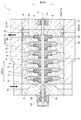
図1及び図2は、一実施形態に係る遠心圧縮機の断面図である。図2は、遠心圧縮機の吐出口における径方向に沿った断面図であり、図1は、図2のI−I断面を示す図である。
図1に示すように、遠心圧縮機1は、ケーシング2と、ケーシング2内で回転自在に支持されるロータ7を備えている。ロータ7は、シャフト4と、シャフト4の外面に固定されている複数段のインペラ8と、を有する。
In the following, as an example of a centrifugal compressor, a multi-stage centrifugal compressor equipped with a multi-stage impeller will be described as an example.
1 and 2 are cross-sectional views of a centrifugal compressor according to an embodiment. FIG. 2 is a cross-sectional view taken along the radial direction at the discharge port of the centrifugal compressor, and FIG. 1 is a view showing an I-I cross section of FIG.
As shown in FIG. 1, the
ケーシング2の内部には、軸方向に配列される複数のダイアフラム10が収容されている。複数のダイアフラム10は、インペラ8を外周側から囲うように設けられている。また、ケーシング2の内周側において、複数のダイアフラム10の軸方向における両側には、ケーシングヘッド5,6が設けられている。
ロータ7は、ラジアル軸受20,22及びスラスト軸受24より回転可能に支持されており、回転軸Oの周りを回転するようになっている。
Inside the
The
なお、複数のダイアフラム10は、ケーシング2に収容される遠心圧縮機1の内部部品の一種である。ケーシング2に収容される内部部品には、ダイアフラム10の他に、インペラ8を含むロータ7も含まれる。
The plurality of
ケーシング2の一端部には、外部からの流体が流入する吸込口16が設けられているとともに、ケーシング2の他端部には、遠心圧縮機1で圧縮された流体を外部に排出するための吐出口18が設けられている。ケーシング2の内部には、複数段のインペラ8間を繋ぐように形成された流路9が形成されており、吸込口16と吐出口18とは、複数のインペラ8及び流路9を介して連通している。
なお、図示する実施形態において、ケーシング2内部の流路9は、複数のダイアフラム10によって少なくとも部分的に形成されている。
One end of the
In the illustrated embodiment, the
図1及び図2に示すように、複数段のインペラ8のうち最も下流側に設けられる最終段インペラ8Aと、ケーシング2の吐出口18との間には、周方向に沿って流路断面積が変化するように設けられた環状流路であるスクロール流路30が形成されている。また、スクロール流路30と吐出口18とは、ケーシング2に形成された出口流路19を介して接続されている。
As shown in FIGS. 1 and 2, a flow path cross-sectional area is provided along the circumferential direction between the
吸込口16を介して遠心圧縮機1に流入した流体は、複数段のインペラ8及び流路9を通って上流から下流へと流れ、複数段のインペラ8を通過する際に、インペラ8の遠心力が付与されることにより段階的に圧縮される。複数段のインペラ8のうち最下流側に設けられる最終段インペラ8Aを通過した圧縮流体は、スクロール流路30及び吐出口18を介して遠心圧縮機1から排出されるようになっている。
The fluid flowing into the
なお、ケーシングヘッド5,6のシャフト4による貫通部には、この貫通部を介した流体の漏れを防止するための軸封装置が設けられていてもよい。図1に示す実施形態では、吸込口16側のケーシングヘッド6に軸封装置26が設けられている。
The penetration portion of the casing heads 5 and 6 by the
図1に示すように、複数のダイアフラム10は、スクロール流路30を形成する表面を有する第1ダイアフラム12と、軸方向において第1ダイアフラム12の隣に配置される第2ダイアフラム14と、を含む。
As shown in FIG. 1, the plurality of
図3は、図1に示す遠心圧縮機1の断面の第1ダイアフラム12及び第2ダイアフラム14の周辺の拡大図である。
FIG. 3 is an enlarged view of the periphery of the
図1〜図3に示す実施形態では、第1ダイアフラム12と第2ダイアフラム14とは、ボルト34によって締結されることにより連結されている。第1ダイアフラム12及び第2ダイアフラム14には、それぞれ、雌ネジが形成されたボルト孔58,60(図3参照)を有しており、ボルト34がボルト孔58,60にねじ込まれることにより、第1ダイアフラム12と第2ダイアフラム14とが締結される。
In the embodiment shown in FIGS. 1 to 3, the
なお、図1〜図3に示す実施形態では、第1ダイアフラム12と第2ダイアフラム14との間に位置する軸方向スペーサ32は、雌ネジが形成されたボルト挿通孔33(図3参照)を含む。そして、上述のボルト34は、ボルト孔58,60及びボルト挿通孔33にねじ込まれることにより、第1ダイアフラム12と第2ダイアフラム14との間に軸方向スペーサ32が配置された状態で、第1ダイアフラム12と第2ダイアフラム14とが締結されるようになっている。
In the embodiment shown in FIGS. 1 to 3, the
幾つかの実施形態では、第1ダイアフラム12と第2ダイアフラム14とは、溶接によって連結されていてもよい。
In some embodiments, the
なお、第1ダイアフラム12と第2ダイアフラム14との間以外のダイアフラム10間の接続は、溶接によって行われていてもよい。
The connection between the
第1ダイアフラム12は、軸方向における両端面である第1端面62及び第2端面64を有する。第1端面62は、吐出口18側に位置するケーシングヘッド5側の端面であり、第2端面64は、第2ダイアフラム14側の端面である。また、第1端面62と第2端面64との間の軸方向の位置範囲において、第1ダイアフラム12の外周面11よりも径方向内側に凹んだ凹部65が形成されており、該凹部65は、径方向に沿った一対の側面52,54と、周方向に沿った底面13を有する。すなわち、底面13は、外周面11よりも径方向内側に位置する表面である。
The
図2及び図3に示すように、スクロール流路30は、内周側の壁面であるスクロール内周壁30aと、外周側の壁面であるスクロール外周壁30bと、によって形成される。そして、スクロール内周壁30aは第1ダイアフラム12の上述の凹部65の底面13(外周面11よりも径方向内側に位置する第1ダイアフラムの表面)によって形成されるとともに、スクロール外周壁30bの少なくとも一部はケーシング2の内周面3によって形成される。
なお、詳細は後で説明するが、図示する実施形態では、スクロール外周壁30bは、ケーシング2の内周面3と、軸方向スペーサ32の内周面(スペーサ内周面40)と、によって形成されている。
As shown in FIGS. 2 and 3, the
Although details will be described later, in the illustrated embodiment, the scroll outer
なお、図示する実施形態において、第1ダイアフラム12の凹部65の一対の側面52,54は、それぞれ、スクロール流路30の径方向に沿った壁面を形成している。
In the illustrated embodiment, each of the pair of side surfaces 52 and 54 of the
ここで、図6は、従来の遠心圧縮機の径方向断面図(図2に対応する断面図)の一例である。
図6に示す従来の遠心圧縮機101では、スクロール流路30のスクロール内周壁30aは、ダイアフラム112の表面113により形成されるとともに、スクロール外周壁30bは、ダイアフラム112と、該ダイアフラム112の隣に配列されるダイアフラムとの間に設けられる環状スペーサ102の内周面104によって形成されている。
環状スペーサ102の内周面104は、ケーシング2の内周面3等と比べて比較的内径側に位置するので、上述のようにスクロール外周壁30bを環状スペーサ102の内周面104で形成する場合、スクロール外周壁30bを比較的内径側に設けざるを得ない。よって、圧縮機の大型化を回避しながらスクロール流路30の流路面積を十分に確保することが難しく、スクロール断面流速が増加することにより摩擦損失が比較的大きくなると考えられる。
Here, FIG. 6 is an example of a radial cross-sectional view (cross-sectional view corresponding to FIG. 2) of a conventional centrifugal compressor.
In the conventional
Since the inner
一方、図1〜図3に示す例示的な実施形態では、スクロール外周壁30bの少なくとも一部をケーシング2の内周面3によって形成するようにしたので、例えば図6に示すような環状スペーサ102の内周面104によってスクロール外周壁30bを形成する場合に比べ、スクロール外周壁30bを比較的外径側に設けることができる。したがって、ケーシング2を大きくしなくても、スクロール流路面積を拡大してスクロール断面流速を低減し、スクロール流路30における摩擦損失を低減することができる。これにより、遠心圧縮機1の大型化を抑制しながら、スクロール流路30における流体損失を低減することができる。
On the other hand, in the exemplary embodiment shown in FIGS. 1 to 3, at least a part of the scroll outer
図1〜図3に示すように、第1ダイアフラム12と第2ダイアフラム14との間には、軸方向スペーサ32が設けられる。軸方向スペーサ32が設けられることで、第2ダイアフラムに対する第1ダイアフラムの軸方向における位置決めを行うことができる。
また、図1〜図3に示す実施形態では、周方向に複数の軸方向スペーサ32(図示する例では4つの軸方向スペーサ32)が配列されている。これにより、第2ダイアフラムに対する第1ダイアフラムの軸方向における位置決めをより確実に行うことができる。
As shown in FIGS. 1 to 3, an
Further, in the embodiment shown in FIGS. 1 to 3, a plurality of axial spacers 32 (four
軸方向スペーサ32は、軸方向において第1ダイアフラム12と第2ダイアフラム14との間に設けられるが、必ずしも、スクロール流路30に露出するように設けられなくてもよい。
The
例えば、図1〜図3に示す例示的な実施形態では、軸方向スペーサ32は、第1ダイアフラム12の外周側端部において、第1ダイアフラム12の凹部65の一対の側面52,54のうち、第2ダイアフラム14を向く側面52と、第2ダイアフラム14の軸方向における両端面のうち、第1ダイアフラム12に面する端面66との間に設けられている。すなわち、軸方向スペーサ32は、スクロール流路30に露出するように設けられている。
For example, in the exemplary embodiment shown in FIGS. 1 to 3, the
また、他の実施形態では、軸方向スペーサ32は、第1ダイアフラム12と第2ダイアフラム14の互いに向き合う端面(すなわち、第1ダイアフラム12の第2端面64と、第2ダイアフラム14の端面66)の間に設けられていてもよい。すなわち、軸方向スペーサ32は、最終段インペラ8Aの下流側に位置するディフューザ通路56に設けられていてもよい。この場合、軸方向スペーサ32は、スクロール流路30に露出してない。
In another embodiment, the
スクロール外周壁30bを形成するケーシング2の内周面3は、遠心圧縮機1の回転中心(回転軸O)を中心とする円筒形であってもよい。
このように、スクロール外周壁30bを形成するケーシング2の内周面3が遠心圧縮機1の回転中心を中心とする円筒形である場合、該円筒形の内周面3を利用して、スクロール流路30を容易に形成することができる。
The inner
In this way, when the inner
すなわち、スクロール内周壁30aを第1ダイアフラム12の凹部65の底面13(表面)によって形成する一方、単純な円筒形状を有するケーシング2の内周面3によってスクロール外周壁30bを形成することができる。したがって、複雑な流路形状をケーシング2に加工して形成することなく、スクロール流路30を比較的容易に形成することができる。
また、スクロール外周壁30bを形成するケーシング2の内周面3が遠心圧縮機1の回転軸Oを中心とする円筒形であり、ロータ7と同心であるので、遠心圧縮機1の構造を簡素化することができる。
That is, the scroll inner
Further, since the inner
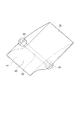
図4は、一実施形態に係る軸方向スペーサ32の斜視図であり、図5は、図2に示す断面図の軸方向スペーサ32周辺の拡大図である。
FIG. 4 is a perspective view of the
図4及び図5に示すように、軸方向スペーサ32は、スクロール内周壁30aに対向するスペーサ内周面40、及び、ケーシング2の内周面3に面するスペーサ外周面43を有する。
As shown in FIGS. 4 and 5, the
上述したように、スクロール外周壁30bは、軸方向スペーサ32のスペーサ内周面40と、ケーシング2の内周面3と、によって形成されていてもよい。
この場合において、幾つかの実施形態では、図5に示すように、スペーサ内周面40は、上流側輪郭部38と、該上流側輪郭部38よりもスクロール流路30におけるスクロール流れの下流側に位置する下流側輪郭部39と、を含む。そして、上流側輪郭部38は、ケーシング2の内周面3に連なるように設けられるとともに、下流側輪郭部39は、軸方向スペーサ32のうち、最も径方向内側に位置する点P1において、上流側輪郭部38に接続されている。
As described above, the scroll outer
In this case, in some embodiments, as shown in FIG. 5, the spacer inner
この場合、ケーシング2の内周面3と、軸方向スペーサ32のスペーサ内周面40とが接続されたスクロール外周壁30bが形成されるので、ケーシング2の内周面3と軸方向スペーサ32の表面とが接続されていない場合に比べて、スクロール流路30内における流体流れの乱れを抑制することができる。よって、スクロール流路30における流体損失を効果的に低減することができる。
In this case, since the scroll outer
図5に示すように、上流側輪郭部38は、径方向外側に向かって凸状である第1湾曲面36と、第1湾曲面36に対してスクロール流れの下流側に位置し、径方向内側に向かって凸状である第2湾曲面37と、を含んでいてもよい。なお、図5に示す例示的な実施形態では、第1湾曲面36と第2湾曲面37とは、点P2において接続されている。
As shown in FIG. 5, the
この場合、スクロール外周壁30bを形成するケーシング2の内周面3とスペーサ内周面40とは、第1湾曲面36及び第2湾曲面37を介して滑らかに接続されるので、スクロール流路30内における流体流れの乱れをより効果的に抑制することができる。これにより、スクロール流路における流体損失をより効果的に低減することができる。
In this case, the inner
また、図5に示すように、下流側輪郭部39は、スクロール流れの下流側に向かうにつれて径方向外側へと周方向に対して斜めに延在する直線により少なくとも部分的に形成されていてもよい。なお、図5に示す例示的な実施形態では、下流側輪郭部39の全体が直線によって形成されている。
Further, as shown in FIG. 5, even if the
この場合、下流側輪郭部39は、スクロール流れの下流側に向かうにつれて径方向外側へと周方向に対して斜めに延在する直線部を含むので、軸方向スペーサ32の加工及び製造管理がしやすくなるとともに、スクロール流路30内における流体流れの乱れを抑制することができる。よって、遠心圧縮機1の製造性を高めながら、スクロール流路30における流体損失を低減することができる。
In this case, since the
上述したように、幾つかの実施形態では、第1ダイアフラム12と第2ダイアフラム14とは、ボルト34によって連結される。この場合において、例えば図3及び図4に示すように、軸方向スペーサ32の各々は、ボルト34のためのボルト挿通孔33を含んでいてもよい。
As mentioned above, in some embodiments, the
この場合、第1ダイアフラム12と第2ダイアフラム14とを連結するためのボルト34は、軸方向スペーサ32のボルト挿通孔33に挿通される。よって、ダイアフラム同士を結合するためにケーシング2の内周面3よりも径方向内側に設けられる上述のボルト34は、スクロール流路30に露出せず軸方向スペーサ32によって覆われるので、ボルト34自体がスクロール流路30を流れる流体の乱れの原因となることはない。よって、スクロール流路30における流体損失を効果的に低減することができる。
In this case, the
幾つかの実施形態では、軸方向スペーサ32の各々は、軸方向における両端部に、第1ダイアフラム12及び第2ダイアフラム14とそれぞれ嵌合する嵌合部を含んでいてもよい。
例えば、図3及び図4に示す軸方向スペーサ32は、軸方向における一端側において第1ダイアフラム12に設けられた第1凹部41に嵌合する第1嵌合部46と、軸方向における他端側において第2ダイアフラム14に設けられた第2凹部42に嵌合する第2嵌合部48と、を含んでいる。なお、第1ダイアフラム12の第1凹部41は、第1ダイアフラム12の凹部65の側面52に設けられており、第2ダイアフラム14の第2凹部42は、第2ダイアフラム14の端面66に設けられている。
In some embodiments, each of the
For example, the
この場合、軸方向スペーサ32の各々は、第1ダイアフラム12に設けられた第1凹部41に嵌合する第1嵌合部46と、第2ダイアフラム14に設けられた第2凹部42に嵌合する第2嵌合部48と、を含むので、各軸方向スペーサ32について、軸方向の周方向又は径方向の位置決めが容易となる。
In this case, each of the
ここで、図2に示す径方向断面において、スクロール外周壁30bのうち、スクロール流れの最も下流側の点をP3とする。また、回転軸Oと、ケーシング2に設けられる吐出口18の中心点と、を通る直線をL1とし、回転軸Oを通り直線L1に直交する直線をL2とし、回転軸Oと点P3とを通る直線をL3とする。また、ケーシング2の外周面における吐出口18の延在範囲のうち、最も点P3に近い点をP4とする(図2参照)。
Here, in the radial cross section shown in FIG. 2, the point on the most downstream side of the scroll flow in the scroll outer
幾つかの実施形態では、直線L2の方向における、点P3の位置と点P4の位置との距離D1はゼロより大きい。
あるいは、幾つかの実施形態では、直線L1とL3との間の角度A1(図2参照)は、直線L2とL3との間の角度A2(図2参照)よりも大きい。
In some embodiments, the distance D1 between the position of the point P3 and the position of the point P4 in the direction of the straight line L2 is greater than zero.
Alternatively, in some embodiments, the angle A1 between the straight lines L1 and L3 (see FIG. 2) is greater than the angle A2 between the straight lines L2 and L3 (see FIG. 2).
この場合、吐出口18付近において、スクロール流路30の流路面積を大きく確保することができ、遠心圧縮機1の大型化を効果的に抑制しながら、スクロール流路における流体損失を低減することができる。
In this case, a large flow path area of the
幾つかの実施形態では、スクロール外周壁30bの一部はケーシング2の内周面3によって形成されるとともに、スクロール外周壁30bの他の部分は少なくとも1つの軸方向スペーサ32のスペーサ内周面40によって形成される。そして、径方向断面(例えば図2に示す断面)において、スクロール外周壁30bのうち、ケーシング2の内周面3によって形成される部分の周方向長さの合計は、スペーサ内周面40によって形成される部分の周方向長さの合計よりも長い。
In some embodiments, a portion of the scroll outer
この場合、スクロール外周壁30bの半分以上の部分はケーシング2の内周面3によって形成されるので、スクロール流路30の流路面積を大きく確保しやすい。このため、遠心圧縮機1の大型化を効果的に抑制しながら、スクロール流路における流体損失を低減することができる。
In this case, since a portion of more than half of the scroll outer
以上、本発明の実施形態について説明したが、本発明は上述した実施形態に限定されることはなく、上述した実施形態に変形を加えた形態や、これらの形態を適宜組み合わせた形態も含む。 Although the embodiments of the present invention have been described above, the present invention is not limited to the above-described embodiments, and includes a modified form of the above-described embodiments and a combination of these embodiments as appropriate.
本明細書において、「ある方向に」、「ある方向に沿って」、「平行」、「直交」、「中心」、「同心」或いは「同軸」等の相対的或いは絶対的な配置を表す表現は、厳密にそのような配置を表すのみならず、公差、若しくは、同じ機能が得られる程度の角度や距離をもって相対的に変位している状態も表すものとする。
例えば、「同一」、「等しい」及び「均質」等の物事が等しい状態であることを表す表現は、厳密に等しい状態を表すのみならず、公差、若しくは、同じ機能が得られる程度の差が存在している状態も表すものとする。
また、本明細書において、四角形状や円筒形状等の形状を表す表現は、幾何学的に厳密な意味での四角形状や円筒形状等の形状を表すのみならず、同じ効果が得られる範囲で、凹凸部や面取り部等を含む形状も表すものとする。
また、本明細書において、一の構成要素を「備える」、「含む」、又は、「有する」という表現は、他の構成要素の存在を除外する排他的な表現ではない。
In the present specification, expressions representing relative or absolute arrangements such as "in a certain direction", "along a certain direction", "parallel", "orthogonal", "center", "concentric" or "coaxial". Strictly represents not only such an arrangement, but also a tolerance or a state of relative displacement at an angle or distance to the extent that the same function can be obtained.
For example, expressions such as "same", "equal", and "homogeneous" that indicate that things are in the same state not only represent exactly the same state, but also have tolerances or differences to the extent that the same function can be obtained. It shall also represent the existing state.
Further, in the present specification, the expression representing a shape such as a quadrangular shape or a cylindrical shape not only represents a shape such as a quadrangular shape or a cylindrical shape in a geometrically strict sense, but also within a range in which the same effect can be obtained. , The shape including the uneven portion, the chamfered portion, etc. shall also be represented.
Further, in the present specification, the expression "comprising", "including", or "having" one component is not an exclusive expression excluding the existence of another component.
1 遠心圧縮機
2 ケーシング
3 内周面
4 シャフト
5 ケーシングヘッド
6 ケーシングヘッド
7 ロータ
8 インペラ
8A 最終段インペラ
9 流路
10 ダイアフラム
11 外周面
12 第1ダイアフラム
13 底面
14 第2ダイアフラム
16 吸込口
18 吐出口
19 出口流路
20 ラジアル軸受
22 ラジアル軸受
24 スラスト軸受
26 軸封装置
30 スクロール流路
30a スクロール内周壁
30b スクロール外周壁
32 軸方向スペーサ
33 ボルト挿通孔
34 ボルト
36 第1湾曲面
37 第2湾曲面
38 上流側輪郭部
39 下流側輪郭部
40 スペーサ内周面
41 第1凹部
42 第2凹部
43 スペーサ外周面
46 第1嵌合部
48 第2嵌合部
52 側面
54 側面
56 ディフューザ通路
58 ボルト孔
60 ボルト孔
62 第1端面
64 第2端面
65 凹部
66 端面
101 遠心圧縮機
102 環状スペーサ
104 内周面
112 ダイアフラム
113 表面
1
Claims (7)
前記複数のダイアフラムの外周側に設けられ、前記複数のダイアフラムを含む内部部品を収容するケーシングと、
前記第1ダイアフラムと前記第2ダイアフラムとの間に設けられる少なくとも一つの軸方向スペーサと、
前記第1ダイアフラムの外周面よりも径方向内側に位置する前記第1ダイアフラムの表面によって形成されるスクロール内周壁、および、前記ケーシングの内周面によって少なくとも一部が形成されるスクロール外周壁によって形成されるスクロール流路と、
を備え、
前記少なくとも一つの軸方向スペーサは、前記ケーシングの前記内周面よりも前記径方向内側において周方向に設けられた複数の軸方向スペーサを含み、
前記複数の軸方向スペーサの各々は、前記スクロール内周壁に対向するスペーサ内周面を有し、
前記複数の軸方向スペーサの各々は、前記周方向における両端である上流端及び下流端を有し、
前記下流端は、前記上流端に対してスクロール流れの下流側に位置し、
前記スクロール外周壁は、前記複数の軸方向スペーサの各々の前記スペーサ内周面と、前記ケーシングの前記内周面と、によって形成され、
前記複数の軸方向スペーサのうち一の軸方向スペーサの前記下流端と、前記複数の軸方向スペーサのうち前記一の軸方向スペーサに対して前記スクロール流れの下流側に位置する他の軸方向スペーサの前記上流端とが、前記周方向にて離間している
ことを特徴とする遠心圧縮機。 A plurality of diaphragms including a first diaphragm and a second diaphragm adjacent to each other in the axial direction, and
A casing provided on the outer peripheral side of the plurality of diaphragms and accommodating internal parts including the plurality of diaphragms, and a casing.
At least one axial spacer provided between the first diaphragm and the second diaphragm,
Formed by a scroll inner peripheral wall formed by the surface of the first diaphragm located radially inside the outer peripheral surface of the first diaphragm, and a scroll outer peripheral wall formed by at least a part by the inner peripheral surface of the casing. Scroll flow path and
Equipped with a,
The at least one axial spacer includes a plurality of axial spacers provided in the circumferential direction inside the inner peripheral surface of the casing in the radial direction.
Each of the plurality of axial spacers has a spacer inner peripheral surface facing the scroll inner peripheral wall.
Each of the plurality of axial spacers has an upstream end and a downstream end which are both ends in the circumferential direction.
The downstream end is located on the downstream side of the scroll flow with respect to the upstream end.
The scroll outer peripheral wall is formed by the inner peripheral surface of each of the plurality of axial spacers and the inner peripheral surface of the casing.
The downstream end of one of the plurality of axial spacers and the other axial spacer located on the downstream side of the scroll flow with respect to the one of the plurality of axial spacers. A centrifugal compressor characterized in that the upstream end of the above is separated from the upstream end in the circumferential direction.
前記ケーシングの前記内周面に連なる上流側輪郭部と、
前記上流側輪郭部に対してスクロール流れの下流側に位置し、前記軸方向スペーサのうち最も径方向内側に位置する点において前記上流側輪郭部に接続される下流側輪郭部と、
を含む
ことを特徴とする請求項1に記載の遠心圧縮機。 The inner peripheral surface of the spacer is
An upstream contour portion connected to the inner peripheral surface of the casing,
A downstream contour portion connected to the upstream contour portion at a point located on the downstream side of the scroll flow with respect to the upstream contour portion and located on the innermost radial direction of the axial spacers.
The centrifugal compressor according to claim 1, characterized in including <br/> things.
前記複数のダイアフラムの外周側に設けられ、前記複数のダイアフラムを含む内部部品を収容するケーシングと、
前記第1ダイアフラムと前記第2ダイアフラムとの間に設けられる少なくとも一つの軸方向スペーサと、
前記第1ダイアフラムの外周面よりも径方向内側に位置する前記第1ダイアフラムの表面によって形成されるスクロール内周壁、および、前記ケーシングの内周面によって少なくとも一部が形成されるスクロール外周壁によって形成されるスクロール流路と、
を備え、
前記少なくとも一つの軸方向スペーサは、前記ケーシングの前記内周面よりも前記径方向内側において周方向に設けられた複数の軸方向スペーサを含み、
前記軸方向スペーサの各々は、前記スクロール内周壁に対向するスペーサ内周面を有し、
前記スペーサ内周面は、
前記ケーシングの前記内周面に連なる上流側輪郭部と、
前記上流側輪郭部に対してスクロール流れの下流側に位置し、前記軸方向スペーサのうち最も径方向内側に位置する点において前記上流側輪郭部に接続される下流側輪郭部と、
を含み、
前記スクロール外周壁は、各々の前記軸方向スペーサの前記スペーサ内周面と、前記ケーシングの前記内周面と、によって形成され、
前記上流側輪郭部は、
径方向外側に向かって凸状である第1湾曲面と、
前記第1湾曲面に対して前記スクロール流れの下流側に位置し、径方向内側に向かって凸状である第2湾曲面と、
を含む
ことを特徴とする遠心圧縮機。 A plurality of diaphragms including a first diaphragm and a second diaphragm adjacent to each other in the axial direction, and
A casing provided on the outer peripheral side of the plurality of diaphragms and accommodating internal parts including the plurality of diaphragms, and a casing.
At least one axial spacer provided between the first diaphragm and the second diaphragm,
Formed by a scroll inner peripheral wall formed by the surface of the first diaphragm located radially inside the outer peripheral surface of the first diaphragm, and a scroll outer peripheral wall formed by at least a part by the inner peripheral surface of the casing. Scroll flow path and
With
The at least one axial spacer includes a plurality of axial spacers provided in the circumferential direction inside the inner peripheral surface of the casing in the radial direction.
Each of the axial spacers has a spacer inner peripheral surface facing the scroll inner peripheral wall.
The inner peripheral surface of the spacer is
An upstream contour portion connected to the inner peripheral surface of the casing,
A downstream contour portion connected to the upstream contour portion at a point located on the downstream side of the scroll flow with respect to the upstream contour portion and located on the innermost radial direction of the axial spacers.
Including
The scroll outer peripheral wall is formed by the spacer inner peripheral surface of each of the axial spacers and the inner peripheral surface of the casing.
The upstream contour portion is
A first curved surface that is convex outward in the radial direction,
A second curved surface located on the downstream side of the scroll flow with respect to the first curved surface and convex inward in the radial direction.
Centrifugal compressor characterized in that it comprises.
前記複数のダイアフラムの外周側に設けられ、前記複数のダイアフラムを含む内部部品を収容するケーシングと、
前記第1ダイアフラムと前記第2ダイアフラムとの間に設けられる少なくとも一つの軸方向スペーサと、
前記第1ダイアフラムの外周面よりも径方向内側に位置する前記第1ダイアフラムの表面によって形成されるスクロール内周壁、および、前記ケーシングの内周面によって少なくとも一部が形成されるスクロール外周壁によって形成されるスクロール流路と、
を備え、
前記少なくとも一つの軸方向スペーサは、前記ケーシングの前記内周面よりも前記径方向内側において周方向に設けられた複数の軸方向スペーサを含み、
前記軸方向スペーサの各々は、前記スクロール内周壁に対向するスペーサ内周面を有し、
前記スペーサ内周面は、
前記ケーシングの前記内周面に連なる上流側輪郭部と、
前記上流側輪郭部に対してスクロール流れの下流側に位置し、前記軸方向スペーサのうち最も径方向内側に位置する点において前記上流側輪郭部に接続される下流側輪郭部と、
を含み、
前記スクロール外周壁は、各々の前記軸方向スペーサの前記スペーサ内周面と、前記ケーシングの前記内周面と、によって形成され、
前記下流側輪郭部は、前記スクロール流れの下流側に向かうにつれて径方向外側へと周方向に対して斜めに延在する直線部を含む
ことを特徴とする遠心圧縮機。 A plurality of diaphragms including a first diaphragm and a second diaphragm adjacent to each other in the axial direction, and
A casing provided on the outer peripheral side of the plurality of diaphragms and accommodating internal parts including the plurality of diaphragms, and a casing.
At least one axial spacer provided between the first diaphragm and the second diaphragm,
Formed by a scroll inner peripheral wall formed by the surface of the first diaphragm located radially inside the outer peripheral surface of the first diaphragm, and a scroll outer peripheral wall formed by at least a part by the inner peripheral surface of the casing. Scroll flow path and
With
The at least one axial spacer includes a plurality of axial spacers provided in the circumferential direction inside the inner peripheral surface of the casing in the radial direction.
Each of the axial spacers has a spacer inner peripheral surface facing the scroll inner peripheral wall.
The inner peripheral surface of the spacer is
An upstream contour portion connected to the inner peripheral surface of the casing,
A downstream contour portion connected to the upstream contour portion at a point located on the downstream side of the scroll flow with respect to the upstream contour portion and located on the innermost radial direction of the axial spacers.
Including
The scroll outer peripheral wall is formed by the spacer inner peripheral surface of each of the axial spacers and the inner peripheral surface of the casing.
The downstream edge portion, centrifugal compressor you comprising a straight portion extending obliquely with respect to the circumferential direction radially outwardly toward the downstream side of the scroll flow.
前記軸方向スペーサの各々は、前記ボルトのためのボルト挿通孔を含む
ことを特徴とする請求項1乃至4の何れか一項に記載の遠心圧縮機。 It is provided with at least one bolt for connecting the first diaphragm and the second diaphragm.
The centrifugal compressor according to any one of claims 1 to 4 , wherein each of the axial spacers includes a bolt insertion hole for the bolt.
一端側において前記第1ダイアフラムに設けられた第1凹部に嵌合する第1嵌合部と、
他端側において前記第2ダイアフラムに設けられた第2凹部に嵌合する第2嵌合部と、
を含む
ことを特徴とする請求項1乃至5の何れか一項に記載の遠心圧縮機。 Each of the axial spacers
A first fitting portion that fits into a first recess provided in the first diaphragm on one end side, and a first fitting portion.
On the other end side, a second fitting portion that fits into the second recess provided in the second diaphragm, and a second fitting portion.
The centrifugal compressor according to any one of claims 1 to 5, wherein the centrifugal compressor comprises.
ことを特徴とする請求項1乃至6の何れか一項に記載の遠心圧縮機。
The centrifuge according to any one of claims 1 to 6 , wherein the inner peripheral surface of the casing forming the scroll outer peripheral wall has a cylindrical shape centered on the rotation center of the centrifugal compressor. Compressor.
Priority Applications (2)
| Application Number | Priority Date | Filing Date | Title |
|---|---|---|---|
| JP2017167059A JP6908472B2 (en) | 2017-08-31 | 2017-08-31 | Centrifugal compressor |
| US16/117,673 US11131319B2 (en) | 2017-08-31 | 2018-08-30 | Centrifugal compressor |
Applications Claiming Priority (1)
| Application Number | Priority Date | Filing Date | Title |
|---|---|---|---|
| JP2017167059A JP6908472B2 (en) | 2017-08-31 | 2017-08-31 | Centrifugal compressor |
Publications (2)
| Publication Number | Publication Date |
|---|---|
| JP2019044659A JP2019044659A (en) | 2019-03-22 |
| JP6908472B2 true JP6908472B2 (en) | 2021-07-28 |
Family
ID=65437302
Family Applications (1)
| Application Number | Title | Priority Date | Filing Date |
|---|---|---|---|
| JP2017167059A Expired - Fee Related JP6908472B2 (en) | 2017-08-31 | 2017-08-31 | Centrifugal compressor |
Country Status (2)
| Country | Link |
|---|---|
| US (1) | US11131319B2 (en) |
| JP (1) | JP6908472B2 (en) |
Families Citing this family (3)
| Publication number | Priority date | Publication date | Assignee | Title |
|---|---|---|---|---|
| JP6908472B2 (en) * | 2017-08-31 | 2021-07-28 | 三菱重工コンプレッサ株式会社 | Centrifugal compressor |
| JP7013316B2 (en) * | 2018-04-26 | 2022-01-31 | 三菱重工コンプレッサ株式会社 | Centrifugal compressor |
| JP2025117889A (en) * | 2024-01-31 | 2025-08-13 | 三菱重工コンプレッサ株式会社 | centrifugal compressor |
Family Cites Families (59)
| Publication number | Priority date | Publication date | Assignee | Title |
|---|---|---|---|---|
| US1669581A (en) * | 1924-04-15 | 1928-05-15 | Spencer Turbine Co | Device for causing flow of fluid |
| US3060335A (en) * | 1961-02-07 | 1962-10-23 | Garrett Corp | Fluid cooled dynamoelectric machine |
| US3355878A (en) * | 1965-08-30 | 1967-12-05 | Birmann Rudolph | Turbocompressor system |
| US3584973A (en) * | 1969-09-30 | 1971-06-15 | Ingersoll Rand Co | Modular turbo compressor unit |
| US4311004A (en) * | 1979-10-26 | 1982-01-19 | Rotoflow Corporation | Gas compression system and method |
| CH684495A5 (en) * | 1991-09-04 | 1994-09-30 | Escher Wyss Ag | Turbomachinery. |
| EP0853735A1 (en) * | 1995-10-06 | 1998-07-22 | Sulzer Turbo AG | Rotodynamic machine for conveying a fluid |
| WO1999028013A2 (en) * | 1997-12-01 | 1999-06-10 | Questair Technologies, Inc. | Modular pressure swing adsorption apparatus |
| US6905535B2 (en) * | 1998-12-16 | 2005-06-14 | Questair Technologies Inc. | Gas separation with split stream centrifugal turbomachinery |
| JP2001289050A (en) * | 1999-05-20 | 2001-10-19 | Hitachi Ltd | Variable capacity turbocharger |
| US6231302B1 (en) * | 1999-06-08 | 2001-05-15 | G. Fonda Bonardi | Thermal control system for gas-bearing turbocompressors |
| US6314894B1 (en) * | 2000-08-30 | 2001-11-13 | Jakel Incorporated | Furnace blower housing with integrally formed exhaust transition |
| DE10048237A1 (en) * | 2000-09-29 | 2002-04-11 | Daimler Chrysler Ag | Exhaust gas turbocharger, supercharged internal combustion engine and method therefor |
| EP1422400B1 (en) * | 2001-08-03 | 2011-12-21 | Akita Fine Blanking Co., Ltd. | Variable blade manufacturing method for a vgs type turbo charger |
| EP1394364B1 (en) * | 2002-08-26 | 2006-03-08 | BorgWarner Inc. | Turbocharger and annular guide conduit therefor |
| EP1418311B1 (en) * | 2002-11-11 | 2007-01-17 | BorgWarner Inc. | Variable geometry vanes array for a turbocharger |
| US7124582B2 (en) * | 2004-07-26 | 2006-10-24 | International Engine Intellectual Property Company, Llc | Method and apparatus for determining turbocharger boost |
| GB2417523B (en) * | 2004-08-23 | 2009-07-08 | Frank Mohn Flatoey As | Rotodynamic fluid machine |
| US7644585B2 (en) * | 2004-08-31 | 2010-01-12 | The United States Of America As Represented By The Administrator Of The U.S. Environmental Protection Agency | Multi-stage turbocharging system with efficient bypass |
| GB2425332A (en) * | 2005-04-23 | 2006-10-25 | Siemens Ind Turbomachinery Ltd | Providing swirl to the compressor of a turbocharger |
| US7942646B2 (en) * | 2006-05-22 | 2011-05-17 | University of Central Florida Foundation, Inc | Miniature high speed compressor having embedded permanent magnet motor |
| US8156757B2 (en) * | 2006-10-06 | 2012-04-17 | Aff-Mcquay Inc. | High capacity chiller compressor |
| JP4909405B2 (en) * | 2007-04-20 | 2012-04-04 | 三菱重工業株式会社 | Centrifugal compressor |
| DE102007029004A1 (en) * | 2007-06-23 | 2008-12-24 | Ihi Charging Systems International Gmbh | Exhaust gas turbocharger for an internal combustion engine |
| US8061976B2 (en) * | 2007-07-16 | 2011-11-22 | Borgwarner Inc. | Variable geometry turbocharger, vane ring assembly with retaining member |
| JP5452991B2 (en) * | 2008-07-10 | 2014-03-26 | ボーグワーナー インコーポレーテッド | Variable geometry vane ring assembly with stepped spacers |
| DE102008039085A1 (en) * | 2008-08-21 | 2010-02-25 | Daimler Ag | Internal combustion engine with an exhaust gas turbocharger |
| US9017017B2 (en) * | 2009-04-10 | 2015-04-28 | Honeywell Internatonal Inc. | Variable-vane assembly having fixed guide pins for unison ring |
| IT1399171B1 (en) * | 2009-07-10 | 2013-04-11 | Nuovo Pignone Spa | HIGH PRESSURE COMPRESSION UNIT FOR INDUSTRIAL PLANT PROCESS FLUIDS AND RELATED OPERATING METHOD |
| CN102482990B (en) * | 2009-09-10 | 2016-10-19 | 博格华纳公司 | The aerofluxus feeding mechanism of the turbine wheel of exhaust turbine supercharger |
| IT1396885B1 (en) * | 2009-12-17 | 2012-12-20 | Nuovo Pignone Spa | INTERMEDIATE GAS BEARING |
| EP2524144B1 (en) * | 2010-01-15 | 2018-10-10 | Dresser-Rand Company | Integral compressor-expander |
| WO2012057885A1 (en) * | 2010-10-27 | 2012-05-03 | Dresser-Rand Company | Multiple motor drivers for a hermetically-sealed motor-compressor system |
| US9200643B2 (en) * | 2010-10-27 | 2015-12-01 | Dresser-Rand Company | Method and system for cooling a motor-compressor with a closed-loop cooling circuit |
| DE102011010454A1 (en) * | 2011-02-05 | 2012-08-09 | Daimler Ag | Turbine for an exhaust gas turbocharger |
| JP5696566B2 (en) * | 2011-03-31 | 2015-04-08 | 株式会社Ihi | Combustor for gas turbine engine and gas turbine engine |
| JP5934786B2 (en) * | 2011-05-10 | 2016-06-15 | ボーグワーナー インコーポレーテッド | Turbocharger with variable turbine shape |
| BR112013030687A2 (en) * | 2011-06-01 | 2017-06-27 | Dresser Rand Co | subsea motor compressor cooling system |
| US9476428B2 (en) * | 2011-06-01 | 2016-10-25 | R & D Dynamics Corporation | Ultra high pressure turbomachine for waste heat recovery |
| US10954792B2 (en) * | 2013-03-15 | 2021-03-23 | Sonic Blue Aerospace, Inc. | Superconducting power shaft core |
| EP2984300B1 (en) * | 2013-03-15 | 2021-02-24 | Imperial College Innovations Limited | Asymmetric double-entry turbine |
| JP6037906B2 (en) * | 2013-03-21 | 2016-12-07 | 三菱重工業株式会社 | Centrifugal fluid machine |
| JP6124659B2 (en) * | 2013-04-15 | 2017-05-10 | 株式会社日立製作所 | Multistage centrifugal fluid machine |
| EP3032108B8 (en) * | 2013-08-06 | 2020-06-17 | IHI Corporation | Centrifugal compressor and turbocharger |
| US9777746B2 (en) * | 2013-09-03 | 2017-10-03 | Dresser-Rand Company | Motor cooling system manifold |
| JP6128230B2 (en) * | 2013-10-31 | 2017-05-17 | 株式会社Ihi | Centrifugal compressor and turbocharger |
| ITFI20130283A1 (en) * | 2013-11-22 | 2015-05-23 | Nuovo Pignone Srl | "MOTOR-COMPRESSOR WITH STAGE IMPELLERS INTEGRATED IN THE MOTOR-ROTORS" |
| CA2962897C (en) * | 2014-09-29 | 2019-08-06 | New Way Machine Components, Inc. | Porous media ventless seal |
| CN104675452A (en) * | 2015-02-25 | 2015-06-03 | 康跃科技股份有限公司 | Variable-section exhaust gas-bypassing turbine meeting EGR (Exhaust Gas Recirculation) requirement |
| US9890700B2 (en) * | 2014-11-21 | 2018-02-13 | Ford Global Technologies, Llc | Systems and methods for a variable geometry turbine nozzle |
| WO2016120984A1 (en) * | 2015-01-27 | 2016-08-04 | 三菱重工コンプレッサ株式会社 | Centrifugal compressor casing and centrifugal compressor |
| US10227889B2 (en) * | 2015-02-05 | 2019-03-12 | Garrett Transportation I Inc. | Variable geometry nozzle for partitioned volute |
| JP2016180400A (en) | 2015-03-25 | 2016-10-13 | 三菱重工業株式会社 | Centrifugal compressor |
| WO2016185592A1 (en) * | 2015-05-21 | 2016-11-24 | 三菱重工業株式会社 | Compressor |
| US10527093B2 (en) * | 2015-07-20 | 2020-01-07 | Us Synthetic Corporation | Bearing assemblies including at least one superhard bearing element having selected surface characteristics and methods of manufacture |
| WO2018003632A1 (en) * | 2016-07-01 | 2018-01-04 | 株式会社Ihi | Centrifugal compressor |
| JP6908472B2 (en) * | 2017-08-31 | 2021-07-28 | 三菱重工コンプレッサ株式会社 | Centrifugal compressor |
| JP7013316B2 (en) * | 2018-04-26 | 2022-01-31 | 三菱重工コンプレッサ株式会社 | Centrifugal compressor |
| JP7204524B2 (en) * | 2019-02-25 | 2023-01-16 | 三菱重工コンプレッサ株式会社 | compressor |
-
2017
- 2017-08-31 JP JP2017167059A patent/JP6908472B2/en not_active Expired - Fee Related
-
2018
- 2018-08-30 US US16/117,673 patent/US11131319B2/en active Active
Also Published As
| Publication number | Publication date |
|---|---|
| JP2019044659A (en) | 2019-03-22 |
| US20190063457A1 (en) | 2019-02-28 |
| US11131319B2 (en) | 2021-09-28 |
Similar Documents
| Publication | Publication Date | Title |
|---|---|---|
| CN104105886B (en) | Rotary machine | |
| US10774839B2 (en) | Device for generating a dynamic axial thrust to balance the overall axial thrust of a radial rotating machine | |
| US10408221B2 (en) | Turbocharger | |
| JP6234600B2 (en) | Turbine | |
| JP6336134B2 (en) | Centrifugal compressor casing and centrifugal compressor | |
| JP6908472B2 (en) | Centrifugal compressor | |
| US11261746B2 (en) | Turbine and turbocharger | |
| US20200355198A1 (en) | Impeller for centrifugal compressor, centrifugal compressor, and turbocharger | |
| US11493054B2 (en) | Impeller of rotating machine and rotating machine | |
| WO2016129039A1 (en) | Supercharger | |
| US11236669B2 (en) | Turbine and turbocharger | |
| JP7013316B2 (en) | Centrifugal compressor | |
| EP3505769B1 (en) | Multiblade centrifugal fan | |
| US20190107052A1 (en) | Turbocharger | |
| US12435730B2 (en) | Impeller of centrifugal compressor and centrifugal compressor | |
| CN111448396B (en) | Variable stator blade and compressor | |
| JPWO2019097611A1 (en) | Compressor impeller, compressor and turbocharger | |
| US11493052B2 (en) | Bearing and turbocharger | |
| JP2023167166A (en) | Multistage centrifugal compressor and adjustment method of the same |
Legal Events
| Date | Code | Title | Description |
|---|---|---|---|
| A711 | Notification of change in applicant |
Free format text: JAPANESE INTERMEDIATE CODE: A711 Effective date: 20180507 |
|
| A625 | Written request for application examination (by other person) |
Free format text: JAPANESE INTERMEDIATE CODE: A625 Effective date: 20200619 |
|
| A977 | Report on retrieval |
Free format text: JAPANESE INTERMEDIATE CODE: A971007 Effective date: 20210409 |
|
| A131 | Notification of reasons for refusal |
Free format text: JAPANESE INTERMEDIATE CODE: A131 Effective date: 20210420 |
|
| A521 | Request for written amendment filed |
Free format text: JAPANESE INTERMEDIATE CODE: A523 Effective date: 20210519 |
|
| TRDD | Decision of grant or rejection written | ||
| A01 | Written decision to grant a patent or to grant a registration (utility model) |
Free format text: JAPANESE INTERMEDIATE CODE: A01 Effective date: 20210615 |
|
| A61 | First payment of annual fees (during grant procedure) |
Free format text: JAPANESE INTERMEDIATE CODE: A61 Effective date: 20210701 |
|
| R150 | Certificate of patent or registration of utility model |
Ref document number: 6908472 Country of ref document: JP Free format text: JAPANESE INTERMEDIATE CODE: R150 |
|
| LAPS | Cancellation because of no payment of annual fees |