WO2015019804A1 - Flywheel regeneration system, and method of controlling same - Google Patents
Flywheel regeneration system, and method of controlling same Download PDFInfo
- Publication number
- WO2015019804A1 WO2015019804A1 PCT/JP2014/068794 JP2014068794W WO2015019804A1 WO 2015019804 A1 WO2015019804 A1 WO 2015019804A1 JP 2014068794 W JP2014068794 W JP 2014068794W WO 2015019804 A1 WO2015019804 A1 WO 2015019804A1
- Authority
- WO
- WIPO (PCT)
- Prior art keywords
- flywheel
- clutch
- kinetic energy
- transmission
- regeneration system
- Prior art date
Links
Images
Classifications
-
- B—PERFORMING OPERATIONS; TRANSPORTING
- B60—VEHICLES IN GENERAL
- B60K—ARRANGEMENT OR MOUNTING OF PROPULSION UNITS OR OF TRANSMISSIONS IN VEHICLES; ARRANGEMENT OR MOUNTING OF PLURAL DIVERSE PRIME-MOVERS IN VEHICLES; AUXILIARY DRIVES FOR VEHICLES; INSTRUMENTATION OR DASHBOARDS FOR VEHICLES; ARRANGEMENTS IN CONNECTION WITH COOLING, AIR INTAKE, GAS EXHAUST OR FUEL SUPPLY OF PROPULSION UNITS IN VEHICLES
- B60K6/00—Arrangement or mounting of plural diverse prime-movers for mutual or common propulsion, e.g. hybrid propulsion systems comprising electric motors and internal combustion engines ; Control systems therefor, i.e. systems controlling two or more prime movers, or controlling one of these prime movers and any of the transmission, drive or drive units Informative references: mechanical gearings with secondary electric drive F16H3/72; arrangements for handling mechanical energy structurally associated with the dynamo-electric machine H02K7/00; machines comprising structurally interrelated motor and generator parts H02K51/00; dynamo-electric machines not otherwise provided for in H02K see H02K99/00
- B60K6/08—Prime-movers comprising combustion engines and mechanical or fluid energy storing means
- B60K6/10—Prime-movers comprising combustion engines and mechanical or fluid energy storing means by means of a chargeable mechanical accumulator, e.g. flywheel
- B60K6/105—Prime-movers comprising combustion engines and mechanical or fluid energy storing means by means of a chargeable mechanical accumulator, e.g. flywheel the accumulator being a flywheel
-
- B—PERFORMING OPERATIONS; TRANSPORTING
- B60—VEHICLES IN GENERAL
- B60W—CONJOINT CONTROL OF VEHICLE SUB-UNITS OF DIFFERENT TYPE OR DIFFERENT FUNCTION; CONTROL SYSTEMS SPECIALLY ADAPTED FOR HYBRID VEHICLES; ROAD VEHICLE DRIVE CONTROL SYSTEMS FOR PURPOSES NOT RELATED TO THE CONTROL OF A PARTICULAR SUB-UNIT
- B60W10/00—Conjoint control of vehicle sub-units of different type or different function
- B60W10/02—Conjoint control of vehicle sub-units of different type or different function including control of driveline clutches
-
- B—PERFORMING OPERATIONS; TRANSPORTING
- B60—VEHICLES IN GENERAL
- B60W—CONJOINT CONTROL OF VEHICLE SUB-UNITS OF DIFFERENT TYPE OR DIFFERENT FUNCTION; CONTROL SYSTEMS SPECIALLY ADAPTED FOR HYBRID VEHICLES; ROAD VEHICLE DRIVE CONTROL SYSTEMS FOR PURPOSES NOT RELATED TO THE CONTROL OF A PARTICULAR SUB-UNIT
- B60W10/00—Conjoint control of vehicle sub-units of different type or different function
- B60W10/24—Conjoint control of vehicle sub-units of different type or different function including control of energy storage means
-
- B—PERFORMING OPERATIONS; TRANSPORTING
- B60—VEHICLES IN GENERAL
- B60W—CONJOINT CONTROL OF VEHICLE SUB-UNITS OF DIFFERENT TYPE OR DIFFERENT FUNCTION; CONTROL SYSTEMS SPECIALLY ADAPTED FOR HYBRID VEHICLES; ROAD VEHICLE DRIVE CONTROL SYSTEMS FOR PURPOSES NOT RELATED TO THE CONTROL OF A PARTICULAR SUB-UNIT
- B60W30/00—Purposes of road vehicle drive control systems not related to the control of a particular sub-unit, e.g. of systems using conjoint control of vehicle sub-units, or advanced driver assistance systems for ensuring comfort, stability and safety or drive control systems for propelling or retarding the vehicle
- B60W30/18—Propelling the vehicle
- B60W30/18009—Propelling the vehicle related to particular drive situations
- B60W30/18027—Drive off, accelerating from standstill
-
- B—PERFORMING OPERATIONS; TRANSPORTING
- B60—VEHICLES IN GENERAL
- B60W—CONJOINT CONTROL OF VEHICLE SUB-UNITS OF DIFFERENT TYPE OR DIFFERENT FUNCTION; CONTROL SYSTEMS SPECIALLY ADAPTED FOR HYBRID VEHICLES; ROAD VEHICLE DRIVE CONTROL SYSTEMS FOR PURPOSES NOT RELATED TO THE CONTROL OF A PARTICULAR SUB-UNIT
- B60W30/00—Purposes of road vehicle drive control systems not related to the control of a particular sub-unit, e.g. of systems using conjoint control of vehicle sub-units, or advanced driver assistance systems for ensuring comfort, stability and safety or drive control systems for propelling or retarding the vehicle
- B60W30/18—Propelling the vehicle
- B60W30/18009—Propelling the vehicle related to particular drive situations
- B60W30/18109—Braking
- B60W30/18127—Regenerative braking
-
- F—MECHANICAL ENGINEERING; LIGHTING; HEATING; WEAPONS; BLASTING
- F16—ENGINEERING ELEMENTS AND UNITS; GENERAL MEASURES FOR PRODUCING AND MAINTAINING EFFECTIVE FUNCTIONING OF MACHINES OR INSTALLATIONS; THERMAL INSULATION IN GENERAL
- F16D—COUPLINGS FOR TRANSMITTING ROTATION; CLUTCHES; BRAKES
- F16D48/00—External control of clutches
- F16D48/06—Control by electric or electronic means, e.g. of fluid pressure
- F16D48/062—Control by electric or electronic means, e.g. of fluid pressure of a clutch system with a plurality of fluid actuated clutches
-
- F—MECHANICAL ENGINEERING; LIGHTING; HEATING; WEAPONS; BLASTING
- F16—ENGINEERING ELEMENTS AND UNITS; GENERAL MEASURES FOR PRODUCING AND MAINTAINING EFFECTIVE FUNCTIONING OF MACHINES OR INSTALLATIONS; THERMAL INSULATION IN GENERAL
- F16D—COUPLINGS FOR TRANSMITTING ROTATION; CLUTCHES; BRAKES
- F16D48/00—External control of clutches
- F16D48/06—Control by electric or electronic means, e.g. of fluid pressure
- F16D48/08—Regulating clutch take-up on starting
-
- B—PERFORMING OPERATIONS; TRANSPORTING
- B60—VEHICLES IN GENERAL
- B60W—CONJOINT CONTROL OF VEHICLE SUB-UNITS OF DIFFERENT TYPE OR DIFFERENT FUNCTION; CONTROL SYSTEMS SPECIALLY ADAPTED FOR HYBRID VEHICLES; ROAD VEHICLE DRIVE CONTROL SYSTEMS FOR PURPOSES NOT RELATED TO THE CONTROL OF A PARTICULAR SUB-UNIT
- B60W2510/00—Input parameters relating to a particular sub-units
- B60W2510/10—Change speed gearings
- B60W2510/1005—Transmission ratio engaged
-
- B—PERFORMING OPERATIONS; TRANSPORTING
- B60—VEHICLES IN GENERAL
- B60W—CONJOINT CONTROL OF VEHICLE SUB-UNITS OF DIFFERENT TYPE OR DIFFERENT FUNCTION; CONTROL SYSTEMS SPECIALLY ADAPTED FOR HYBRID VEHICLES; ROAD VEHICLE DRIVE CONTROL SYSTEMS FOR PURPOSES NOT RELATED TO THE CONTROL OF A PARTICULAR SUB-UNIT
- B60W2510/00—Input parameters relating to a particular sub-units
- B60W2510/10—Change speed gearings
- B60W2510/1015—Input shaft speed, e.g. turbine speed
-
- B—PERFORMING OPERATIONS; TRANSPORTING
- B60—VEHICLES IN GENERAL
- B60W—CONJOINT CONTROL OF VEHICLE SUB-UNITS OF DIFFERENT TYPE OR DIFFERENT FUNCTION; CONTROL SYSTEMS SPECIALLY ADAPTED FOR HYBRID VEHICLES; ROAD VEHICLE DRIVE CONTROL SYSTEMS FOR PURPOSES NOT RELATED TO THE CONTROL OF A PARTICULAR SUB-UNIT
- B60W2510/00—Input parameters relating to a particular sub-units
- B60W2510/24—Energy storage means
-
- B—PERFORMING OPERATIONS; TRANSPORTING
- B60—VEHICLES IN GENERAL
- B60W—CONJOINT CONTROL OF VEHICLE SUB-UNITS OF DIFFERENT TYPE OR DIFFERENT FUNCTION; CONTROL SYSTEMS SPECIALLY ADAPTED FOR HYBRID VEHICLES; ROAD VEHICLE DRIVE CONTROL SYSTEMS FOR PURPOSES NOT RELATED TO THE CONTROL OF A PARTICULAR SUB-UNIT
- B60W2540/00—Input parameters relating to occupants
- B60W2540/10—Accelerator pedal position
-
- B—PERFORMING OPERATIONS; TRANSPORTING
- B60—VEHICLES IN GENERAL
- B60W—CONJOINT CONTROL OF VEHICLE SUB-UNITS OF DIFFERENT TYPE OR DIFFERENT FUNCTION; CONTROL SYSTEMS SPECIALLY ADAPTED FOR HYBRID VEHICLES; ROAD VEHICLE DRIVE CONTROL SYSTEMS FOR PURPOSES NOT RELATED TO THE CONTROL OF A PARTICULAR SUB-UNIT
- B60W2552/00—Input parameters relating to infrastructure
- B60W2552/15—Road slope
-
- B—PERFORMING OPERATIONS; TRANSPORTING
- B60—VEHICLES IN GENERAL
- B60W—CONJOINT CONTROL OF VEHICLE SUB-UNITS OF DIFFERENT TYPE OR DIFFERENT FUNCTION; CONTROL SYSTEMS SPECIALLY ADAPTED FOR HYBRID VEHICLES; ROAD VEHICLE DRIVE CONTROL SYSTEMS FOR PURPOSES NOT RELATED TO THE CONTROL OF A PARTICULAR SUB-UNIT
- B60W2710/00—Output or target parameters relating to a particular sub-units
- B60W2710/02—Clutches
- B60W2710/025—Clutch slip, i.e. difference between input and output speeds
-
- B—PERFORMING OPERATIONS; TRANSPORTING
- B60—VEHICLES IN GENERAL
- B60W—CONJOINT CONTROL OF VEHICLE SUB-UNITS OF DIFFERENT TYPE OR DIFFERENT FUNCTION; CONTROL SYSTEMS SPECIALLY ADAPTED FOR HYBRID VEHICLES; ROAD VEHICLE DRIVE CONTROL SYSTEMS FOR PURPOSES NOT RELATED TO THE CONTROL OF A PARTICULAR SUB-UNIT
- B60W2710/00—Output or target parameters relating to a particular sub-units
- B60W2710/02—Clutches
- B60W2710/027—Clutch torque
-
- B—PERFORMING OPERATIONS; TRANSPORTING
- B60—VEHICLES IN GENERAL
- B60W—CONJOINT CONTROL OF VEHICLE SUB-UNITS OF DIFFERENT TYPE OR DIFFERENT FUNCTION; CONTROL SYSTEMS SPECIALLY ADAPTED FOR HYBRID VEHICLES; ROAD VEHICLE DRIVE CONTROL SYSTEMS FOR PURPOSES NOT RELATED TO THE CONTROL OF A PARTICULAR SUB-UNIT
- B60W2710/00—Output or target parameters relating to a particular sub-units
- B60W2710/10—Change speed gearings
- B60W2710/1005—Transmission ratio engaged
-
- F—MECHANICAL ENGINEERING; LIGHTING; HEATING; WEAPONS; BLASTING
- F16—ENGINEERING ELEMENTS AND UNITS; GENERAL MEASURES FOR PRODUCING AND MAINTAINING EFFECTIVE FUNCTIONING OF MACHINES OR INSTALLATIONS; THERMAL INSULATION IN GENERAL
- F16D—COUPLINGS FOR TRANSMITTING ROTATION; CLUTCHES; BRAKES
- F16D2500/00—External control of clutches by electric or electronic means
- F16D2500/10—System to be controlled
- F16D2500/102—Actuator
- F16D2500/1026—Hydraulic
-
- F—MECHANICAL ENGINEERING; LIGHTING; HEATING; WEAPONS; BLASTING
- F16—ENGINEERING ELEMENTS AND UNITS; GENERAL MEASURES FOR PRODUCING AND MAINTAINING EFFECTIVE FUNCTIONING OF MACHINES OR INSTALLATIONS; THERMAL INSULATION IN GENERAL
- F16D—COUPLINGS FOR TRANSMITTING ROTATION; CLUTCHES; BRAKES
- F16D2500/00—External control of clutches by electric or electronic means
- F16D2500/10—System to be controlled
- F16D2500/108—Gear
- F16D2500/1088—CVT
-
- F—MECHANICAL ENGINEERING; LIGHTING; HEATING; WEAPONS; BLASTING
- F16—ENGINEERING ELEMENTS AND UNITS; GENERAL MEASURES FOR PRODUCING AND MAINTAINING EFFECTIVE FUNCTIONING OF MACHINES OR INSTALLATIONS; THERMAL INSULATION IN GENERAL
- F16D—COUPLINGS FOR TRANSMITTING ROTATION; CLUTCHES; BRAKES
- F16D2500/00—External control of clutches by electric or electronic means
- F16D2500/30—Signal inputs
- F16D2500/31—Signal inputs from the vehicle
- F16D2500/3108—Vehicle speed
-
- F—MECHANICAL ENGINEERING; LIGHTING; HEATING; WEAPONS; BLASTING
- F16—ENGINEERING ELEMENTS AND UNITS; GENERAL MEASURES FOR PRODUCING AND MAINTAINING EFFECTIVE FUNCTIONING OF MACHINES OR INSTALLATIONS; THERMAL INSULATION IN GENERAL
- F16D—COUPLINGS FOR TRANSMITTING ROTATION; CLUTCHES; BRAKES
- F16D2500/00—External control of clutches by electric or electronic means
- F16D2500/70—Details about the implementation of the control system
- F16D2500/704—Output parameters from the control unit; Target parameters to be controlled
- F16D2500/70402—Actuator parameters
- F16D2500/7041—Position
-
- Y—GENERAL TAGGING OF NEW TECHNOLOGICAL DEVELOPMENTS; GENERAL TAGGING OF CROSS-SECTIONAL TECHNOLOGIES SPANNING OVER SEVERAL SECTIONS OF THE IPC; TECHNICAL SUBJECTS COVERED BY FORMER USPC CROSS-REFERENCE ART COLLECTIONS [XRACs] AND DIGESTS
- Y02—TECHNOLOGIES OR APPLICATIONS FOR MITIGATION OR ADAPTATION AGAINST CLIMATE CHANGE
- Y02T—CLIMATE CHANGE MITIGATION TECHNOLOGIES RELATED TO TRANSPORTATION
- Y02T10/00—Road transport of goods or passengers
- Y02T10/10—Internal combustion engine [ICE] based vehicles
- Y02T10/40—Engine management systems
-
- Y—GENERAL TAGGING OF NEW TECHNOLOGICAL DEVELOPMENTS; GENERAL TAGGING OF CROSS-SECTIONAL TECHNOLOGIES SPANNING OVER SEVERAL SECTIONS OF THE IPC; TECHNICAL SUBJECTS COVERED BY FORMER USPC CROSS-REFERENCE ART COLLECTIONS [XRACs] AND DIGESTS
- Y02—TECHNOLOGIES OR APPLICATIONS FOR MITIGATION OR ADAPTATION AGAINST CLIMATE CHANGE
- Y02T—CLIMATE CHANGE MITIGATION TECHNOLOGIES RELATED TO TRANSPORTATION
- Y02T10/00—Road transport of goods or passengers
- Y02T10/60—Other road transportation technologies with climate change mitigation effect
- Y02T10/62—Hybrid vehicles
Definitions
- the present invention relates to a flywheel regeneration system and a control method thereof.
- JP2012-516417A has a flywheel that can be connected / disconnected by a flywheel clutch on the input shaft of the transmission, and when the vehicle decelerates, the flywheel clutch is engaged and the flywheel is rotated by the rotation input from the drive wheels,
- a flywheel regenerative system for converting vehicle kinetic energy into flywheel kinetic energy is disclosed.
- flywheel regeneration system if the flywheel clutch is released, the regenerated kinetic energy can be stored in the flywheel, and if the flywheel clutch is engaged during start-up or acceleration, it is stored in the flywheel.
- the released kinetic energy can be released and used for starting and accelerating the vehicle.
- the flywheel regeneration system described above when the vehicle is started using the kinetic energy stored in the flywheel, if the flywheel clutch is engaged without considering the stored kinetic energy, the driver Unintended startability may occur. For example, when creeping is performed in a state where the kinetic energy stored in the flywheel is large, if the flywheel clutch is engaged, the driving force generated by the drive wheels increases, and the vehicle may start or accelerate suddenly.
- This invention solves such a problem, and when starting using the kinetic energy preserve
- a flywheel regeneration system includes a transmission provided between a drive source and a drive wheel, a flywheel that can be engaged with an input shaft side of the transmission, a flywheel, and a transmission. And a flywheel clutch that connects and disconnects the power transmission between the flywheel and the transmission. When the vehicle decelerates, the flywheel clutch is engaged, and the flywheel is rotated by the kinetic energy during deceleration.
- a flywheel regeneration system that performs regeneration and includes a start control unit that controls the engagement state of the flywheel clutch based on the kinetic energy stored in the flywheel when the vehicle starts.
- a control method for a flywheel regeneration system includes a transmission provided between a drive source and a drive wheel, a flywheel that can be engaged with an input shaft of the transmission, and a flywheel. Between the flywheel and the transmission, and a flywheel clutch that connects and disconnects the power transmission between the flywheel and the transmission. The flywheel clutch is engaged when the vehicle decelerates, and the flywheel is driven by the kinetic energy during deceleration.
- the engagement state of the flywheel clutch is controlled based on the kinetic energy of the flywheel when starting the vehicle, it is possible to suppress the startability unintended by the driver when starting the vehicle.
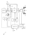
- FIG. 1 is a schematic configuration diagram of a vehicle in the present embodiment.
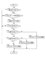
- FIG. 2 is a flowchart for explaining the vehicle start control according to this embodiment.
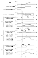
- FIG. 3 is a time chart showing changes in the engagement torque capacity of the flywheel clutch when the vehicle starts.
- FIG. 1 shows an overall configuration of a vehicle 100 provided with a flywheel regeneration system according to an embodiment of the present invention.
- the vehicle 100 decelerates the output rotation of the engine 1 as a power source, a flywheel 2 for regeneration, a continuously variable transmission (hereinafter referred to as CVT) 3 that continuously changes the output rotation of the engine 1, and the CVT 3.
- CVT continuously variable transmission
- a final reduction gear 4, a differential 5, left and right drive wheels 6, a hydraulic circuit 7, and a controller 8 are provided.
- the engine clutch CL1 is provided between the engine 1 and the input shaft 3in of the CVT 3.
- the engine clutch CL1 is a clutch that is engaged and released by operating the electric actuator 30, and electrically controls the engagement torque capacity.
- a hydraulic clutch capable of controlling the fastening torque capacity by the supplied hydraulic pressure may be used.
- a start clutch CL2 is provided between the CVT 3 and the final speed reducer 4 to transmit the rotation from the engine 1 or the flywheel 2 input through the CVT 3 to the final speed reducer 4 when starting.
- the starting clutch CL2 is a hydraulic clutch capable of controlling the fastening torque capacity by the supplied hydraulic pressure.
- the oil pump 10 is connected to the input shaft 3in of the CVT 3 via a belt, gear, etc. (not shown).
- the oil pump 10 is a gear pump type or vane pump type oil pump that generates hydraulic pressure when the input shaft 3in of the CVT 3 rotates.
- the hydraulic pressure generated by the oil pump 10 is sent to the hydraulic circuit 7 and supplied from the hydraulic circuit 7 to the pulley of the CVT 3 and the start clutch CL2.
- flywheel 2 can be engaged with the input shaft 3 in of the CVT 3 via a pair of reduction gear trains 11 and 12 and a flywheel clutch CLfw.
- the flywheel 2 is a metal cylinder or disk, and is housed in a container that is vacuumed or decompressed to reduce windage loss during rotation.
- a flywheel clutch CLfw is provided between the reduction gear train 11 and the reduction gear train 12.
- the flywheel clutch CLfw is an electric clutch that can be switched between an engaged state (engaged, semi-engaged, and released) by the clutch actuator 13, and connects and disconnects power transmission between the flywheel 2 and the input shaft 3in of the CVT 3.
- An electric oil pump may be provided instead of the clutch actuator 13, and the flywheel clutch CLfw may be a hydraulic clutch capable of controlling the fastening torque capacity by the hydraulic pressure generated by the electric oil pump.
- the engagement state of the flywheel clutch CLfw is changed by controlling the engagement torque capacity.
- the hydraulic circuit 7 is configured by a solenoid valve or the like that operates in response to a signal from a controller 8 described later, and is connected to the CVT 3, the engine clutch CL1, the start clutch CL2, and the oil pump 10 through an oil passage.
- the hydraulic circuit 7 generates the hydraulic pressure required by the pulley of the CVT 3 and the start clutch CL2 using the hydraulic pressure generated by the oil pump 10 as the original pressure, and the generated hydraulic pressure is supplied to the pulley of the CVT 3, the engine clutch CL1, and the start clutch CL2. Supply.
- the brake 14 is an electronically controlled brake in which the brake pedal 15 and the master cylinder 16 are mechanically independent.
- the brake actuator 17 displaces the piston of the master cylinder 16, and hydraulic pressure corresponding to the required deceleration (deceleration requested by the driver, the same applies hereinafter) is supplied to the brake 14. Power is generated.
- the brake 14 is also provided on the driven wheel.
- the controller 8 includes a CPU, a RAM, an input / output interface, and the like.
- the controller 8 includes a rotation speed sensor 21 that detects the rotation speed of the engine 1, and a rotation speed sensor 22 that detects the rotation speed Nin of the input shaft 3in of the CVT 3.
- a rotational speed sensor 23 for detecting the rotational speed Nfw of the flywheel 2 a vehicle speed sensor 24 for detecting the vehicle speed VSP, an accelerator opening sensor 26 for detecting the opening APO of the accelerator pedal 25, and the depression amount of the brake pedal 15 by the driver Signals from the brake sensor 27, the gradient sensor 28, etc. are detected.
- the controller 8 performs various calculations based on the input signal, and controls the shift of the CVT 3, the clutch CL 1, CL 2, CLfw engagement state, and the brake actuator 17. In particular, when the driver depresses the brake pedal 15 and the vehicle 100 decelerates, the controller 8 fastens the flywheel clutch CLfw, rotates the flywheel 2 by the rotation input from the drive wheels 6, and the vehicle 100 The kinetic energy of the vehicle 100 is regenerated by converting the kinetic energy it has into the kinetic energy of the flywheel 2.
- the controller 8 controls the engagement torque capacity of the flywheel clutch CLfw so that a braking force (regenerative braking) corresponding to the required deceleration is obtained.
- the controller 8 operates the brake actuator 17 to increase the braking force of the brake 14 to reduce the request. Let speed be realized.
- the regenerated kinetic energy can be stored in the flywheel 2 by releasing the flywheel clutch CLfw. If the flywheel clutch CLfw is engaged in a state where kinetic energy is stored in the flywheel 2, the kinetic energy stored in the flywheel 2 can be used for starting and acceleration of the vehicle 100.
- flywheel start starting the vehicle 100 using the kinetic energy stored in the flywheel 2 is referred to as flywheel start.
- the flywheel 2 itself cannot control the kinetic energy to be released, when the flywheel starts, the flywheel 2 is driven from the flywheel 2 by controlling the fastening torque capacity of the flywheel clutch CLfw.
- the torque transmitted to the wheel 6 is controlled, and a desired driving force is generated by the driving wheel 6.
- step S100 the controller 8 determines whether or not a flywheel start prohibition condition is satisfied.
- the controller 8 is, for example, (a) when the select lever is operated from the N range, (b) when the road surface gradient is equal to or greater than a predetermined gradient, or (c) when the turn signal switch is operated. Or (d) When the hazard switch is operated, it is determined that the flywheel start prohibition condition is satisfied.
- the predetermined gradient is a gradient (uphill gradient) that may cause the vehicle 100 to slide down or the drive wheels 6 to slip when the flywheel starts.
- the flywheel 2 releases kinetic energy
- the flywheel 2 itself cannot control the released kinetic energy.
- a large driving force is required.
- the flywheel clutch CLfw The resolution is insufficient and cannot be controlled accurately. Therefore, if the flywheel starts on a road surface with a large gradient, the vehicle 100 may slide down, and the drive wheel 6 may slip when the road surface resistance is low, which is particularly noticeable in a front-wheel drive vehicle. . Therefore, when the road surface has a predetermined slope or more, flywheel start is prohibited. If the flywheel start prohibition condition is satisfied, the process proceeds to step S106. If the flywheel start prohibition condition is not satisfied, the process proceeds to step S101.
- step S101 the controller 8 determines whether or not to start flywheel. Specifically, the controller 8 determines whether or not the creep travel without the depression of the brake pedal 15 and the depression of the accelerator pedal 25 is requested, and when the creep travel is requested, the flywheel starts. If it is determined that the creep travel is not requested, it is determined that the flywheel is not started. If the flywheel start is performed, the process proceeds to step S102, and if the flywheel start is not performed, the process proceeds to step S106.
- step S102 the controller 8 calculates the kinetic energy of the flywheel 2 based on the signal from the rotational speed sensor 23.
- step S103 the controller 8 determines whether or not the calculated kinetic energy is equal to or less than a first predetermined value.
- the first predetermined value is a value that suppresses the deterioration of the flywheel clutch CLfw and the start clutch CL2 and suppresses the sudden start of the vehicle 100 when creep running is requested.
- the flywheel clutch CLfw or the start clutch CL2 When the kinetic energy of the flywheel 2 is large, that is, when the rotational speed Nfw of the flywheel 2 is high, the flywheel clutch CLfw or the start clutch CL2 is semi-engaged (or fastened) to release the kinetic energy from the flywheel 2. The amount of heat generated by the flywheel clutch CLfw or the start clutch CL2 increases, and the durability of the flywheel clutch CLfw or the start clutch CL2 may be reduced.
- the engagement torque capacity of the flywheel clutch CLfw must be controlled so that torque suitable for creep running is transmitted.
- the kinetic energy of the flywheel 2 is large, it is necessary to control so that the torque is transmitted slightly by reducing the fastening torque capacity.
- the resolution is insufficient in a region where the engagement torque capacity of the flywheel clutch CLfw is small, the engagement torque capacity of the flywheel clutch CLfw cannot be controlled to a value suitable for creep travel in such a case.
- the power transmission in the clutch CLfw is larger than a desired value, a large driving force is generated in the vehicle 100 and the vehicle 100 may start suddenly.
- the first predetermined value is set so as not to start the flywheel in such a case. If the calculated kinetic energy is less than or equal to the first predetermined value, the process proceeds to step S104. If the calculated kinetic energy is greater than the first predetermined value, the process proceeds to step S106.
- step S104 the controller 8 determines whether or not the calculated kinetic energy is equal to or less than a second predetermined value.
- the second predetermined value is a value that enables creep travel even if the flywheel clutch CLfw is not half-engaged and is engaged.
- the process proceeds to step S105, and when the calculated kinetic energy is greater than the second predetermined value, the process proceeds to step S107.
- step S105 the controller 8 determines whether or not the calculated kinetic energy is greater than a third predetermined value.
- the third predetermined value is a value set based on the oil amount balance limit.
- the CVT 3 and the starting clutch CL2 are operated by hydraulic pressure, and a predetermined hydraulic pressure is required to operate the CVT 3 and the starting clutch CL2 normally.
- the oil amount balance limit is a hydraulic pressure necessary for normal operation of the CVT 3, the starting clutch CL2, and the like.
- the discharge pressure of the oil pump 10 is also small, which may be below the oil amount balance limit.
- the third predetermined value is set so that the discharge pressure of the oil pump 10 does not fall below the oil amount balance limit when the flywheel starts. If the calculated kinetic energy is less than or equal to the third predetermined value, the process proceeds to step S106, and if the calculated kinetic energy is greater than the third predetermined value, the process proceeds to step S108.
- step S106 the controller 8 starts the engine 1 with the flywheel clutch CLfw released, engages the engine clutch CL1 and the start clutch CL2, and starts the vehicle 100.
- the controller 8 does not start the flywheel, the kinetic energy of the flywheel 2 is greater than the first predetermined value, or the kinetic energy of the flywheel 2 is equal to or less than the third predetermined value. In this case, the kinetic energy is not released from the flywheel 2, and the engine 1 is started to start the vehicle 100.
- step S107 the controller 8 semi-engages the flywheel clutch CLfw, engages the start clutch CL2, and starts the vehicle 100 using the flywheel 2.
- the controller 8 controls the engagement torque capacity of the flywheel clutch CLfw so as to perform creep running. Specifically, first, a target driving force determined from the vehicle speed VSP and the opening APO of the accelerator pedal 25 is calculated, and the target slip of the flywheel clutch CLfw is calculated from the target driving force and the current rotational speed and gradient of the flywheel 2. The amount is calculated, the engagement torque capacity of the flywheel clutch CLfw is determined, and feedback control is performed. In addition, when making it slip only with one clutch, the emitted-heat amount becomes large.
- the starting clutch CL2 similarly calculates the engagement torque capacity from the clutch input side rotational speed, the output side rotational speed (vehicle speed VSP), and the opening degree APO of the accelerator pedal 25, and aims
- the hydraulic pressure is supplied from the hydraulic circuit 7 so that the fastening torque capacity is as follows.
- step S108 the controller 8 fastens the flywheel clutch CLfw, fastens the start clutch CL2, and starts the vehicle 100 using the kinetic energy of the flywheel 2.
- the controller 8 engages the flywheel clutch CLfw to start the vehicle 100, and then the engine 1 Is started, the engine clutch CL1 is engaged, and the vehicle 100 is started by the driving force from the engine 1.
- the engagement control of the flywheel clutch CLfw increases the engagement torque capacity by a predetermined increase amount determined based on the oil temperature and the rotational speed of the flywheel 2 after the piston stroke. Complete fastening is performed and the fastening control is terminated.
- the starting clutch CL2 is set to a semi-engaged state to control the vehicle speed VSP.
- the rotational speed of the flywheel 2 and the respective fastening torque capacities when the kinetic energy of the flywheel 2 is equal to or lower than the second predetermined value and larger than the third predetermined value are indicated by alternate long and short dash lines ((c) in FIG. 3). ).
- the brake pedal 15 is not depressed and the vehicle 100 starts.
- the accelerator pedal 25 is not depressed, and the vehicle 100 performs creep running.
- the engagement torque capacity of the flywheel clutch CLfw is maintained at zero at time t0 as shown in FIG. CLfw is released. Further, the engine 1 is started at time t0, the engagement torque capacity of the engine clutch CL1 is increased, the oil pump 10 is driven to generate hydraulic pressure, and the start clutch CL2 is engaged, so that the creep travel by the engine 1 is performed. Do. Thereafter, at time t2, when the accelerator pedal 25 is stepped on and an acceleration request is made, the creep travel is terminated.
- the flywheel clutch CLfw is set to the vehicle speed VSP at time t0 as shown in FIG.
- the fastening torque capacity is appropriately controlled by the fastening torque capacity calculated from the rotational speed of the flywheel 2 and the opening degree APO of the accelerator pedal 25 to make a semi-fastened state, and the creep running by the flywheel 2 is performed.
- the engagement torque capacity is calculated from the clutch input side rotational speed, the output side rotational speed (vehicle speed VSP), and the opening degree APO of the accelerator pedal 25. It controls so that it may be in a half-fastened state with the fastened torque capacity. Note that the engagement torque capacity of the engine clutch CL1 is maintained at zero, and the engine clutch CL1 is released.
- flywheel clutch CLfw When the flywheel clutch CLfw is semi-engaged and the vehicle 100 is started, the kinetic energy of the flywheel 2 gradually decreases, and when the kinetic energy of the flywheel 2 falls below the second predetermined value at time t1, the flywheel clutch CLfw The fastening torque capacity is increased in order to completely fasten. Thereafter, at time t2, when the accelerator pedal 25 is stepped on and an acceleration request is made, the creep travel is terminated. Accordingly, flywheel clutch CLfw is released, engine clutch CL1 is engaged, and engine 1 is started to accelerate vehicle 100.
- the fastening torque capacity is increased by a predetermined amount determined based on the temperature and the rotational speed of the flywheel 2 to engage the flywheel clutch CLfw, and creep travel is performed by the flywheel 2.
- the starting clutch CL2 is set in a semi-engaged state so as to prevent an unintended acceleration feeling, and the vehicle speed VSP is controlled. Note that the engagement torque capacity of the engine clutch CL1 is maintained at zero, and the engine clutch CL1 is released.
- flywheel clutch CLfw When starting, if the kinetic energy of the flywheel 2 is greater than the first predetermined value, the flywheel clutch CLfw is released. Thereby, it can suppress that a big torque is transmitted from the flywheel 2 to the driving wheel 6, and it can suppress that the vehicle 100 starts suddenly. Moreover, it can suppress that calorific value of flywheel clutch CLfw etc. becomes large, and can suppress that durability, such as flywheel clutch CLfw, falls.
- the flywheel clutch CLfw When starting, if the kinetic energy of the flywheel 2 is below the first predetermined value, the flywheel clutch CLfw is semi-engaged. As a result, a desired driving force can be generated in the vehicle 100 to achieve acceleration intended by the driver, and creep running can be performed using the kinetic energy of the flywheel 2.
- the flywheel clutch CLfw When starting, if the kinetic energy of the flywheel 2 is less than or equal to the second predetermined value, the flywheel clutch CLfw is engaged. Accordingly, power loss in the flywheel clutch CLfw can be reduced, acceleration intended by the driver can be realized, and creep running can be performed using the kinetic energy of the flywheel 2.
- flywheel start is prohibited and the engine 1 starts. Since the engine 1 can control the torque to be generated, the vehicle 100 can be prevented from sliding down and the drive wheels 6 can be prevented from slipping even when the road surface has a large gradient.
- the flywheel is started when creep travel without depression of the accelerator pedal 25 is requested.
- the accelerator pedal 25 is depressed at the time of departure and the vehicle 100 is requested to accelerate. Even if it is a case, you may perform a flywheel start.
- the controller 8 determines whether the flywheel clutch CLfw is half-engaged or engaged based on the kinetic energy of the flywheel 2. , The vehicle 100 is accelerated by releasing kinetic energy from the flywheel 2. If the acceleration request cannot be achieved by the kinetic energy of the flywheel 2, the controller 8 engages the engine clutch CL ⁇ b> 1, starts the engine 1, and accelerates the vehicle 100 by the engine 1.
- the vehicle 100 that performs creep travel in a state where the brake pedal 15 is not depressed and the accelerator pedal 25 is not depressed is described. However, the brake pedal 15 is not depressed and the accelerator pedal 25 is depressed. There may be a vehicle 100 that does not start the vehicle 100 in a state where there is not. Such a vehicle 100 performs a start corresponding to creep travel when the accelerator pedal 25 is slightly depressed, but the start control of the above-described embodiment may be performed during such a start.
- the vehicle 100 includes only the engine 1 as a power source, but may include the engine 1 and a motor as power sources, or may include only a motor instead of the engine 1.
- the vehicle 100 includes the CVT 3 as a transmission
- the type of the transmission is not limited to this, and may include a stepped transmission instead of the CVT 3.
- the engine clutch CL1 is interposed between the engine 1 and the CVT 3, but a torque converter is provided between the engine 1 and the CVT 3, and the flywheel clutch CLfw is connected to the torque converter. May be.
Abstract
A flywheel regeneration system is provided: with a transmission; a flywheel engageable with the input shaft side of the transmission; and a flywheel clutch which is disposed between the flywheel and the transmission and which connects or disconnects power transmission between the flywheel and the transmission. When the vehicle decelerates, the flywheel clutch is engaged and regeneration is performed by rotating the flywheel with the kinetic energy during deceleration. The flywheel regeneration system is provided with a start control means that controls the engaged state of the flywheel clutch on the basis of the kinetic energy stored in the flywheel when the vehicle starts.
Description
本発明はフライホイール回生システム及びその制御方法に関するものである。
The present invention relates to a flywheel regeneration system and a control method thereof.
車両の燃費・電費を向上させるには、車両が減速する時に車両の運動エネルギーを電気的又は機械的に回生し、回生したエネルギーを発進時や加速時に利用するのが有効である。
In order to improve the fuel consumption and electricity consumption of the vehicle, it is effective to regenerate the kinetic energy of the vehicle electrically or mechanically when the vehicle decelerates and use the regenerated energy at the start or acceleration.
JP2012-516417Aは、変速機の入力軸にフライホイールクラッチによって断接可能なフライホイールを設け、車両が減速する時にフライホイールクラッチを締結して駆動輪から入力される回転でフライホイールを回転させ、車両の運動エネルギーをフライホイールの運動エネルギーに変換するフライホイール回生システムを開示している。
JP2012-516417A has a flywheel that can be connected / disconnected by a flywheel clutch on the input shaft of the transmission, and when the vehicle decelerates, the flywheel clutch is engaged and the flywheel is rotated by the rotation input from the drive wheels, A flywheel regenerative system for converting vehicle kinetic energy into flywheel kinetic energy is disclosed.
このようなフライホイール回生システムにおいては、フライホイールクラッチを解放すれば回生した運動エネルギーをフライホイールに保存することができ、また、発進時や加速時にフライホイールクラッチを締結すれば、フライホイールに保存された運動エネルギーを放出させ、車両の発進や加速に利用することができる。
In such a flywheel regeneration system, if the flywheel clutch is released, the regenerated kinetic energy can be stored in the flywheel, and if the flywheel clutch is engaged during start-up or acceleration, it is stored in the flywheel. The released kinetic energy can be released and used for starting and accelerating the vehicle.
しかし、上記するフライホイール回生システムでは、フライホイールに保存された運動エネルギーを利用して車両を発進させる場合に、保存されている運動エネルギーを考慮せずにフライホイールクラッチを締結すると、運転者が意図しない発進性が生じるおそれがある。例えば、フライホイールに保存された運動エネルギーが大きい状態でクリープ走行を行う場合に、フライホイールクラッチを締結すると駆動輪で発生する駆動力が大きくなり、車両が急発進又は急加速するおそれがある。
However, in the flywheel regeneration system described above, when the vehicle is started using the kinetic energy stored in the flywheel, if the flywheel clutch is engaged without considering the stored kinetic energy, the driver Unintended startability may occur. For example, when creeping is performed in a state where the kinetic energy stored in the flywheel is large, if the flywheel clutch is engaged, the driving force generated by the drive wheels increases, and the vehicle may start or accelerate suddenly.
本発明はこのような問題点を解決するものであり、フライホイールに保存された運動エネルギーを利用して発進させる場合に、運転者が意図しない発進性が生じることを抑制することを目的とする。
This invention solves such a problem, and when starting using the kinetic energy preserve | saved at the flywheel, it aims at suppressing that the start property which a driver | operator does not intend arises. .
本発明のある態様に係るフライホイール回生システムは、駆動源と駆動輪との間に設けられた変速機と、変速機の入力軸側に係合可能なフライホイールと、フライホイールと変速機との間に設けられ、フライホイールと変速機との間の動力伝達を断接するフライホイールクラッチとを備え、車両が減速する時にフライホイールクラッチを締結し、減速時の運動エネルギーで前記フライホイールを回転させて回生を行うフライホイール回生システムであって、車両が発進する時に、フライホイールに保存された運動エネルギーに基づいてフライホイールクラッチの締結状態を制御する発進制御手段を備える。
A flywheel regeneration system according to an aspect of the present invention includes a transmission provided between a drive source and a drive wheel, a flywheel that can be engaged with an input shaft side of the transmission, a flywheel, and a transmission. And a flywheel clutch that connects and disconnects the power transmission between the flywheel and the transmission. When the vehicle decelerates, the flywheel clutch is engaged, and the flywheel is rotated by the kinetic energy during deceleration. A flywheel regeneration system that performs regeneration and includes a start control unit that controls the engagement state of the flywheel clutch based on the kinetic energy stored in the flywheel when the vehicle starts.
本発明の別の態様に係るフライホイール回生システムの制御方法は、駆動源と駆動輪との間に設けられた変速機と、変速機の入力軸側に係合可能なフライホイールと、フライホイールと変速機との間に設けられ、フライホイールと変速機との間の動力伝達を断接するフライホイールクラッチとを備え、車両が減速する時にフライホイールクラッチを締結し、減速時の運動エネルギーでフライホイールを回転させて回生を行うフライホイール回生システムを制御するフライホイール回生システムの制御方法であって、車両が発進する時に、フライホイールに保存された運動エネルギーを算出し、算出した運動エネルギーに基づいてフライホイールクラッチの締結状態を制御する。
A control method for a flywheel regeneration system according to another aspect of the present invention includes a transmission provided between a drive source and a drive wheel, a flywheel that can be engaged with an input shaft of the transmission, and a flywheel. Between the flywheel and the transmission, and a flywheel clutch that connects and disconnects the power transmission between the flywheel and the transmission. The flywheel clutch is engaged when the vehicle decelerates, and the flywheel is driven by the kinetic energy during deceleration. A flywheel regenerative system control method for controlling a flywheel regenerative system that regenerates by rotating a wheel, and calculates kinetic energy stored in the flywheel when the vehicle starts, and based on the calculated kinetic energy To control the engaged state of the flywheel clutch.
これらの態様によると、車両発進時に、フライホイールの運動エネルギーに基づいてフライホイールクラッチの締結状態が制御されるので、車両発進時に運転者が意図しない発進性が生じることを抑制することができる。
According to these aspects, since the engagement state of the flywheel clutch is controlled based on the kinetic energy of the flywheel when starting the vehicle, it is possible to suppress the startability unintended by the driver when starting the vehicle.
以下、添付図面を参照しながら本発明の実施形態について説明する。
Hereinafter, embodiments of the present invention will be described with reference to the accompanying drawings.
図1は、本発明の実施形態に係るフライホイール回生システムを備えた車両100の全体構成を示している。
FIG. 1 shows an overall configuration of a vehicle 100 provided with a flywheel regeneration system according to an embodiment of the present invention.
車両100は、動力源としてのエンジン1と、回生用のフライホイール2と、エンジン1の出力回転を無段階に変速する無段変速機(以下、CVT)3と、CVT3の出力回転を減速する終減速装置4と、差動装置5と、左右の駆動輪6と、油圧回路7と、コントローラ8とを備えている。
The vehicle 100 decelerates the output rotation of the engine 1 as a power source, a flywheel 2 for regeneration, a continuously variable transmission (hereinafter referred to as CVT) 3 that continuously changes the output rotation of the engine 1, and the CVT 3. A final reduction gear 4, a differential 5, left and right drive wheels 6, a hydraulic circuit 7, and a controller 8 are provided.
エンジン1とCVT3の入力軸3inとの間には、エンジンクラッチCL1が設けられている。エンジンクラッチCL1は、電動アクチュエータ30を作動することにより締結解放動作するクラッチであり、電気的に締結トルク容量を制御する。なお、供給される油圧によって締結トルク容量を制御可能な油圧式クラッチでもよい。
The engine clutch CL1 is provided between the engine 1 and the input shaft 3in of the CVT 3. The engine clutch CL1 is a clutch that is engaged and released by operating the electric actuator 30, and electrically controls the engagement torque capacity. A hydraulic clutch capable of controlling the fastening torque capacity by the supplied hydraulic pressure may be used.
CVT3と終減速装置4の間には、発進時に締結され、CVT3を介して入力されるエンジン1又はフライホイール2からの回転を終減速装置4に伝達する発進クラッチCL2が設けられている。発進クラッチCL2は、供給される油圧によって締結トルク容量を制御可能な油圧式クラッチである。
A start clutch CL2 is provided between the CVT 3 and the final speed reducer 4 to transmit the rotation from the engine 1 or the flywheel 2 input through the CVT 3 to the final speed reducer 4 when starting. The starting clutch CL2 is a hydraulic clutch capable of controlling the fastening torque capacity by the supplied hydraulic pressure.
CVT3の入力軸3inには図示しないベルト、ギヤ等を介してオイルポンプ10が接続されている。オイルポンプ10は、CVT3の入力軸3inが回転すると油圧を発生させるギヤポンプ式又はベーンポンプ式のオイルポンプである。オイルポンプ10で発生した油圧は油圧回路7へ送られ、油圧回路7からCVT3のプーリ、発進クラッチCL2に供給される。
The oil pump 10 is connected to the input shaft 3in of the CVT 3 via a belt, gear, etc. (not shown). The oil pump 10 is a gear pump type or vane pump type oil pump that generates hydraulic pressure when the input shaft 3in of the CVT 3 rotates. The hydraulic pressure generated by the oil pump 10 is sent to the hydraulic circuit 7 and supplied from the hydraulic circuit 7 to the pulley of the CVT 3 and the start clutch CL2.
CVT3の入力軸3inには、さらに、一対の減速ギヤ列11、12及びフライホイールクラッチCLfwを介してフライホイール2が係合可能となっている。フライホイール2は、金属製の円筒体又は円盤であり、回転時の風損を低減するために真空又は減圧された容器内に収容されている。
Further, the flywheel 2 can be engaged with the input shaft 3 in of the CVT 3 via a pair of reduction gear trains 11 and 12 and a flywheel clutch CLfw. The flywheel 2 is a metal cylinder or disk, and is housed in a container that is vacuumed or decompressed to reduce windage loss during rotation.
減速ギヤ列11と減速ギヤ列12との間にはフライホイールクラッチCLfwが設けられている。フライホイールクラッチCLfwは、クラッチアクチュエータ13によって締結状態(締結、半締結、解放)を切り換えることのできる電動クラッチであり、フライホイール2とCVT3の入力軸3inとの間の動力伝達を断接する。クラッチアクチュエータ13に代えて電動オイルポンプを設け、フライホイールクラッチCLfwを、電動オイルポンプで発生した油圧によって締結トルク容量を制御可能な油圧式クラッチとしてもよい。フライホイールクラッチCLfwは、締結トルク容量が制御されることで、締結状態が変更される。
A flywheel clutch CLfw is provided between the reduction gear train 11 and the reduction gear train 12. The flywheel clutch CLfw is an electric clutch that can be switched between an engaged state (engaged, semi-engaged, and released) by the clutch actuator 13, and connects and disconnects power transmission between the flywheel 2 and the input shaft 3in of the CVT 3. An electric oil pump may be provided instead of the clutch actuator 13, and the flywheel clutch CLfw may be a hydraulic clutch capable of controlling the fastening torque capacity by the hydraulic pressure generated by the electric oil pump. The engagement state of the flywheel clutch CLfw is changed by controlling the engagement torque capacity.
油圧回路7は、後述するコントローラ8からの信号を受けて動作するソレノイド弁等で構成され、CVT3、エンジンクラッチCL1、発進クラッチCL2及びオイルポンプ10と油路を介して接続される。油圧回路7は、オイルポンプ10で発生した油圧を元圧として、CVT3のプーリ及び発進クラッチCL2で必要とされる油圧を生成し、生成した油圧をCVT3のプーリ、エンジンクラッチCL1及び発進クラッチCL2に供給する。
The hydraulic circuit 7 is configured by a solenoid valve or the like that operates in response to a signal from a controller 8 described later, and is connected to the CVT 3, the engine clutch CL1, the start clutch CL2, and the oil pump 10 through an oil passage. The hydraulic circuit 7 generates the hydraulic pressure required by the pulley of the CVT 3 and the start clutch CL2 using the hydraulic pressure generated by the oil pump 10 as the original pressure, and the generated hydraulic pressure is supplied to the pulley of the CVT 3, the engine clutch CL1, and the start clutch CL2. Supply.
ブレーキ14は、ブレーキペダル15とマスターシリンダ16とが機構的に独立している電子制御式ブレーキである。運転者がブレーキペダル15を踏み込むと、ブレーキアクチュエータ17がマスターシリンダ16のピストンを変位させ、要求減速度(運転者が要求する減速度、以下同じ)に応じた油圧がブレーキ14に供給され、制動力が発生する。なお、図示は省略するが、ブレーキ14は従動輪にも設けられている。
The brake 14 is an electronically controlled brake in which the brake pedal 15 and the master cylinder 16 are mechanically independent. When the driver depresses the brake pedal 15, the brake actuator 17 displaces the piston of the master cylinder 16, and hydraulic pressure corresponding to the required deceleration (deceleration requested by the driver, the same applies hereinafter) is supplied to the brake 14. Power is generated. Although not shown, the brake 14 is also provided on the driven wheel.
コントローラ8は、CPU、RAM、入出力インターフェース等で構成され、コントローラ8には、エンジン1の回転速度を検出する回転速度センサ21、CVT3の入力軸3inの回転速度Ninを検出する回転速度センサ22、フライホイール2の回転速度Nfwを検出する回転速度センサ23、車速VSPを検出する車速センサ24、アクセルペダル25の開度APOを検出するアクセル開度センサ26、運転者によるブレーキペダル15の踏み込み量を検出するブレーキセンサ27、勾配センサ28等からの信号が入力される。
The controller 8 includes a CPU, a RAM, an input / output interface, and the like. The controller 8 includes a rotation speed sensor 21 that detects the rotation speed of the engine 1, and a rotation speed sensor 22 that detects the rotation speed Nin of the input shaft 3in of the CVT 3. , A rotational speed sensor 23 for detecting the rotational speed Nfw of the flywheel 2, a vehicle speed sensor 24 for detecting the vehicle speed VSP, an accelerator opening sensor 26 for detecting the opening APO of the accelerator pedal 25, and the depression amount of the brake pedal 15 by the driver Signals from the brake sensor 27, the gradient sensor 28, etc. are detected.
コントローラ8は、入力される信号に基づき各種演算を行い、CVT3の変速、クラッチCL1、CL2、CLfwの締結状態、ブレーキアクチュエータ17を制御する。特に、運転者がブレーキペダル15を踏み込み、車両100が減速する時は、コントローラ8は、フライホイールクラッチCLfwを締結し、駆動輪6から入力される回転でフライホイール2を回転させ、車両100が持つ運動エネルギーをフライホイール2の運動エネルギーに変換することで、車両100の運動エネルギーを回生する。
The controller 8 performs various calculations based on the input signal, and controls the shift of the CVT 3, the clutch CL 1, CL 2, CLfw engagement state, and the brake actuator 17. In particular, when the driver depresses the brake pedal 15 and the vehicle 100 decelerates, the controller 8 fastens the flywheel clutch CLfw, rotates the flywheel 2 by the rotation input from the drive wheels 6, and the vehicle 100 The kinetic energy of the vehicle 100 is regenerated by converting the kinetic energy it has into the kinetic energy of the flywheel 2.
回生中、コントローラ8は、要求減速度に応じた制動力(回生ブレーキ)が得られるようフライホイールクラッチCLfwの締結トルク容量を制御する。フライホイールクラッチCLfwを締結する前で回生ブレーキを発生できない場合や回生ブレーキのみでは要求減速度を実現できない場合は、コントローラ8はブレーキアクチュエータ17を動作させてブレーキ14の制動力を増大させて要求減速度が実現されるようにする。
During regeneration, the controller 8 controls the engagement torque capacity of the flywheel clutch CLfw so that a braking force (regenerative braking) corresponding to the required deceleration is obtained. When the regenerative brake cannot be generated before the flywheel clutch CLfw is engaged, or when the required deceleration cannot be realized only with the regenerative brake, the controller 8 operates the brake actuator 17 to increase the braking force of the brake 14 to reduce the request. Let speed be realized.
回生された運動エネルギーは、フライホイールクラッチCLfwを解放することによってフライホイール2に保存することができる。そして、フライホイール2に運動エネルギーが保存されている状態でフライホイールクラッチCLfwを締結すれば、フライホイール2に保存されている運動エネルギーを車両100の発進や加速に利用することができる。以下において、フライホイール2に保存されている運動エネルギーを用いて車両100を発進させることをフライホイール発進という。
The regenerated kinetic energy can be stored in the flywheel 2 by releasing the flywheel clutch CLfw. If the flywheel clutch CLfw is engaged in a state where kinetic energy is stored in the flywheel 2, the kinetic energy stored in the flywheel 2 can be used for starting and acceleration of the vehicle 100. Hereinafter, starting the vehicle 100 using the kinetic energy stored in the flywheel 2 is referred to as flywheel start.
フライホイール2はフライホイール2自体で、放出する運動エネルギーを制御することができないので、フライホイール発進を行う場合には、フライホイールクラッチCLfwの締結トルク容量を制御することで、フライホイール2から駆動輪6に伝達されるトルクを制御し、所望される駆動力を駆動輪6で発生させている。
Since the flywheel 2 itself cannot control the kinetic energy to be released, when the flywheel starts, the flywheel 2 is driven from the flywheel 2 by controlling the fastening torque capacity of the flywheel clutch CLfw. The torque transmitted to the wheel 6 is controlled, and a desired driving force is generated by the driving wheel 6.
ここで、車両100の発進制御について図2のフローチャートを用いて説明する。
Here, the start control of the vehicle 100 will be described with reference to the flowchart of FIG.
ステップS100では、コントローラ8は、フライホイール発進禁止条件を満たすかどうか判定する。具体的には、コントローラ8は、例えば(a)セレクトレバーがNレンジから操作された場合、(b)路面の勾配が所定勾配以上である場合、(c)ターンシグナルスイッチが操作されている場合、又は(d)ハザードスイッチが操作されている場合にフライホイール発進禁止条件を満たしていると判定する。なお、所定勾配は、フライホイール発進を行うと車両100がずり下がったり、駆動輪6がスリップしたりするおそれがある勾配(上り勾配)である。フライホイール2は運動エネルギーを放出する場合に、フライホイール2自体で、放出する運動エネルギーを制御することができない。勾配抵抗が大きい登坂路で発進する場合には大きい駆動力が必要となるが、フライホイール2における運動エネルギーの放出量を大きくし、それをフライホイールクラッチCLfwで制御しようとしてもフライホイールクラッチCLfwの分解能が不足し、正確に制御することができない。そのため、勾配が大きい路面でフライホイール発進を行うと、車両100がずり下がるおそれがあり、さらに路面抵抗が小さい場合などに駆動輪6がスリップするおそれがあり、特に前輪駆動の車両において顕著となる。そのため、路面の勾配が所定勾配以上である場合には、フライホイール発進を禁止する。フライホイール発進禁止条件を満たす場合には処理はステップS106に進み、フライホイール発進禁止条件を満たさない場合には処理はステップS101に進む。
In step S100, the controller 8 determines whether or not a flywheel start prohibition condition is satisfied. Specifically, the controller 8 is, for example, (a) when the select lever is operated from the N range, (b) when the road surface gradient is equal to or greater than a predetermined gradient, or (c) when the turn signal switch is operated. Or (d) When the hazard switch is operated, it is determined that the flywheel start prohibition condition is satisfied. The predetermined gradient is a gradient (uphill gradient) that may cause the vehicle 100 to slide down or the drive wheels 6 to slip when the flywheel starts. When the flywheel 2 releases kinetic energy, the flywheel 2 itself cannot control the released kinetic energy. When starting on an uphill road with a large gradient resistance, a large driving force is required. However, even if the amount of kinetic energy released from the flywheel 2 is increased and controlled by the flywheel clutch CLfw, the flywheel clutch CLfw The resolution is insufficient and cannot be controlled accurately. Therefore, if the flywheel starts on a road surface with a large gradient, the vehicle 100 may slide down, and the drive wheel 6 may slip when the road surface resistance is low, which is particularly noticeable in a front-wheel drive vehicle. . Therefore, when the road surface has a predetermined slope or more, flywheel start is prohibited. If the flywheel start prohibition condition is satisfied, the process proceeds to step S106. If the flywheel start prohibition condition is not satisfied, the process proceeds to step S101.
ステップS101では、コントローラ8は、フライホイール発進を行うかどうか判定する。具体的には、コントローラ8は、ブレーキペダル15の踏み込みがなく、かつアクセルペダル25の踏み込みがないクリープ走行が要求されているかどうか判定し、クリープ走行が要求されている場合にはフライホイール発進を行うと判定し、クリープ走行が要求されていない場合にはフライホイール発進を行わないと判定する。フライホイール発進を行う場合には処理はステップS102に進み、フライホイール発進を行わない場合には処理はステップS106に進む。
In step S101, the controller 8 determines whether or not to start flywheel. Specifically, the controller 8 determines whether or not the creep travel without the depression of the brake pedal 15 and the depression of the accelerator pedal 25 is requested, and when the creep travel is requested, the flywheel starts. If it is determined that the creep travel is not requested, it is determined that the flywheel is not started. If the flywheel start is performed, the process proceeds to step S102, and if the flywheel start is not performed, the process proceeds to step S106.
ステップS102では、コントローラ8は、回転速度センサ23からの信号に基づいてフライホイール2の運動エネルギーを算出する。
In step S102, the controller 8 calculates the kinetic energy of the flywheel 2 based on the signal from the rotational speed sensor 23.
ステップS103では、コントローラ8は、算出した運動エネルギーが第1所定値以下であるかどうか判定する。第1所定値は、クリープ走行が要求された場合に、フライホイールクラッチCLfw及び発進クラッチCL2の劣化を抑制し、かつ車両100の急発進を抑制する値である。
In step S103, the controller 8 determines whether or not the calculated kinetic energy is equal to or less than a first predetermined value. The first predetermined value is a value that suppresses the deterioration of the flywheel clutch CLfw and the start clutch CL2 and suppresses the sudden start of the vehicle 100 when creep running is requested.
フライホイール2の運動エネルギーが大きい場合、つまりフライホイール2の回転速度Nfwが高い場合にフライホイールクラッチCLfw、又は発進クラッチCL2を半締結(又は締結)してフライホイール2から運動エネルギーを放出すると、フライホイールクラッチCLfw又は発進クラッチCL2の発熱量が大きくなり、フライホイールクラッチCLfw又は発進クラッチCL2の耐久性が低下するおそれがある。
When the kinetic energy of the flywheel 2 is large, that is, when the rotational speed Nfw of the flywheel 2 is high, the flywheel clutch CLfw or the start clutch CL2 is semi-engaged (or fastened) to release the kinetic energy from the flywheel 2. The amount of heat generated by the flywheel clutch CLfw or the start clutch CL2 increases, and the durability of the flywheel clutch CLfw or the start clutch CL2 may be reduced.
また、フライホイールクラッチCLfwを半締結して車両100をクリープ走行する場合には、クリープ走行に適したトルクが伝達されるようにフライホイールクラッチCLfwの締結トルク容量を制御しなければならない。特に、フライホイール2の運動エネルギーが大きい場合には、締結トルク容量を小さくして僅かにトルクが伝達されるように制御しなければならない。しかし、フライホイールクラッチCLfwの締結トルク容量が小さい領域では分解能が不足するため、このような場合にフライホイールクラッチCLfwの締結トルク容量をクリープ走行に適した値に制御することができず、フライホイールクラッチCLfwにおける動力伝達が所望される値よりも大きい場合には、車両100に大きな駆動力が発生し、車両100が急発進するおそれがある。
Further, when the vehicle 100 creeps with the flywheel clutch CLfw half-engaged, the engagement torque capacity of the flywheel clutch CLfw must be controlled so that torque suitable for creep running is transmitted. In particular, when the kinetic energy of the flywheel 2 is large, it is necessary to control so that the torque is transmitted slightly by reducing the fastening torque capacity. However, since the resolution is insufficient in a region where the engagement torque capacity of the flywheel clutch CLfw is small, the engagement torque capacity of the flywheel clutch CLfw cannot be controlled to a value suitable for creep travel in such a case. When the power transmission in the clutch CLfw is larger than a desired value, a large driving force is generated in the vehicle 100 and the vehicle 100 may start suddenly.
このように、クリープ走行が要求されている場合であっても、フライホイール発進を行わない方が良い場合がある。第1所定値は、このような場合にフライホイール発進を行わないように設定される。算出した運動エネルギーが第1所定値以下である場合には処理はステップS104に進み、算出した運動エネルギーが第1所定値よりも大きい場合には処理はステップS106に進む。
As described above, even when creep driving is required, it may be better not to start the flywheel. The first predetermined value is set so as not to start the flywheel in such a case. If the calculated kinetic energy is less than or equal to the first predetermined value, the process proceeds to step S104. If the calculated kinetic energy is greater than the first predetermined value, the process proceeds to step S106.
ステップS104では、コントローラ8は、算出した運動エネルギーが第2所定値以下かどうか判定する。第2所定値は、フライホイールクラッチCLfwを半締結せず、締結しても、クリープ走行を実現することが可能となる値である。算出された運動エネルギーが第2所定値以下の場合にはステップS105に進み、算出された運動エネルギーが第2所定値よりも大きい場合にはステップS107に進む。
In step S104, the controller 8 determines whether or not the calculated kinetic energy is equal to or less than a second predetermined value. The second predetermined value is a value that enables creep travel even if the flywheel clutch CLfw is not half-engaged and is engaged. When the calculated kinetic energy is less than or equal to the second predetermined value, the process proceeds to step S105, and when the calculated kinetic energy is greater than the second predetermined value, the process proceeds to step S107.
ステップS105では、コントローラ8は、算出した運動エネルギーが第3所定値よりも大きいかどうか判定する。第3所定値は、油量収支限界に基づいて設定される値である。CVT3、発進クラッチCL2などは油圧によって動作しており、CVT3、発進クラッチCL2などを正常に動作させるには所定の油圧が必要となる。油量収支限界は、CVT3、発進クラッチCL2などを正常に動作させるために必要な油圧である。フライホイール発進を行うとオイルポンプ10はフライホイール2によって駆動するので、オイルポンプ10の吐出圧はフライホイール2の運動エネルギー(回転速度)に依存することになる。従って、フライホイール2の運動エネルギーが小さい(回転速度が低い)場合には、オイルポンプ10の吐出圧も小さくなり、油量収支限界を下回るおそれがある。第3所定値は、フライホイール発進時にオイルポンプ10の吐出圧が油量収支限界を下回らないように設定される。算出された運動エネルギーが第3所定値以下の場合には処理はステップS106に進み、算出された運動エネルギーが第3所定値よりも大きい場合には処理はステップS108に進む。
In step S105, the controller 8 determines whether or not the calculated kinetic energy is greater than a third predetermined value. The third predetermined value is a value set based on the oil amount balance limit. The CVT 3 and the starting clutch CL2 are operated by hydraulic pressure, and a predetermined hydraulic pressure is required to operate the CVT 3 and the starting clutch CL2 normally. The oil amount balance limit is a hydraulic pressure necessary for normal operation of the CVT 3, the starting clutch CL2, and the like. When the flywheel starts, the oil pump 10 is driven by the flywheel 2, so that the discharge pressure of the oil pump 10 depends on the kinetic energy (rotational speed) of the flywheel 2. Therefore, when the kinetic energy of the flywheel 2 is small (the rotational speed is low), the discharge pressure of the oil pump 10 is also small, which may be below the oil amount balance limit. The third predetermined value is set so that the discharge pressure of the oil pump 10 does not fall below the oil amount balance limit when the flywheel starts. If the calculated kinetic energy is less than or equal to the third predetermined value, the process proceeds to step S106, and if the calculated kinetic energy is greater than the third predetermined value, the process proceeds to step S108.
ステップS106では、コントローラ8は、フライホイールクラッチCLfwを解放したまま、エンジン1を始動させて、エンジンクラッチCL1及び発進クラッチCL2を締結し、車両100を発進させる。コントローラ8は、フライホイール発進禁止条件を満たす場合、フライホイール発進を行わない場合、フライホイール2の運動エネルギーが第1所定値よりも大きい場合、又はフライホイール2の運動エネルギーが第3所定値以下の場合には、フライホイール2から運動エネルギーの放出を行わず、エンジン1を始動させて車両100を発進させる。
In step S106, the controller 8 starts the engine 1 with the flywheel clutch CLfw released, engages the engine clutch CL1 and the start clutch CL2, and starts the vehicle 100. When the flywheel start prohibition condition is satisfied, the controller 8 does not start the flywheel, the kinetic energy of the flywheel 2 is greater than the first predetermined value, or the kinetic energy of the flywheel 2 is equal to or less than the third predetermined value. In this case, the kinetic energy is not released from the flywheel 2, and the engine 1 is started to start the vehicle 100.
ステップS107では、コントローラ8は、フライホイールクラッチCLfwを半締結し、発進クラッチCL2を締結し、フライホイール2を利用して車両100を発進させる。このとき、フライホイール2の回転自体を制御することができないので、コントローラ8は、クリープ走行となるように、フライホイールクラッチCLfwの締結トルク容量を制御する。具体的には、まず、車速VSPとアクセルペダル25の開度APOから決まる目標駆動力を算出し、当該目標駆動力と現在のフライホイール2の回転速度と勾配とからフライホイールクラッチCLfwの目標スリップ量を算出し、フライホイールクラッチCLfwの締結トルク容量を決定しフィードバック制御を行う。なお、1つのクラッチだけでスリップさせる場合、発熱量が大きくなる。そこで、発熱量を分担するために、発進クラッチCL2も同様に、クラッチ入力側回転速度と出力側回転速度(車速VSP)とアクセルペダル25の開度APOとから、締結トルク容量を算出し、狙いの締結トルク容量となるように油圧回路7から油圧を供給する。
In step S107, the controller 8 semi-engages the flywheel clutch CLfw, engages the start clutch CL2, and starts the vehicle 100 using the flywheel 2. At this time, since the rotation of the flywheel 2 itself cannot be controlled, the controller 8 controls the engagement torque capacity of the flywheel clutch CLfw so as to perform creep running. Specifically, first, a target driving force determined from the vehicle speed VSP and the opening APO of the accelerator pedal 25 is calculated, and the target slip of the flywheel clutch CLfw is calculated from the target driving force and the current rotational speed and gradient of the flywheel 2. The amount is calculated, the engagement torque capacity of the flywheel clutch CLfw is determined, and feedback control is performed. In addition, when making it slip only with one clutch, the emitted-heat amount becomes large. Therefore, in order to share the heat generation amount, the starting clutch CL2 similarly calculates the engagement torque capacity from the clutch input side rotational speed, the output side rotational speed (vehicle speed VSP), and the opening degree APO of the accelerator pedal 25, and aims The hydraulic pressure is supplied from the hydraulic circuit 7 so that the fastening torque capacity is as follows.
ステップS108では、コントローラ8は、フライホイールクラッチCLfwを締結し、発進クラッチCL2を締結し、フライホイール2の運動エネルギーを利用して車両100を発進させる。フライホイール2の運動エネルギーが小さく、フライホイールクラッチCLfwを締結すると、クリープ走行相当の駆動力が発生するので、コントローラ8は、フライホイールクラッチCLfwを締結して車両100を発進させ、その後、エンジン1を始動し、エンジンクラッチCL1を締結してエンジン1からの駆動力で車両100を発進させる。このフライホイールクラッチCLfwの締結制御は、具体的には、ピストンのストロークを行ったあと、油温とフライホイール2の回転速度とに基づいて決められた所定の増加量で締結トルク容量を増加させ完全締結を行い、締結制御を終了する。なお、意図しない加速を行わないために、発進クラッチCL2を半締結状態とし車速VSPをコントロールする。
In step S108, the controller 8 fastens the flywheel clutch CLfw, fastens the start clutch CL2, and starts the vehicle 100 using the kinetic energy of the flywheel 2. When the flywheel 2 has low kinetic energy and the flywheel clutch CLfw is engaged, a driving force equivalent to creep travel is generated. Therefore, the controller 8 engages the flywheel clutch CLfw to start the vehicle 100, and then the engine 1 Is started, the engine clutch CL1 is engaged, and the vehicle 100 is started by the driving force from the engine 1. Specifically, the engagement control of the flywheel clutch CLfw increases the engagement torque capacity by a predetermined increase amount determined based on the oil temperature and the rotational speed of the flywheel 2 after the piston stroke. Complete fastening is performed and the fastening control is terminated. In order to prevent unintended acceleration, the starting clutch CL2 is set to a semi-engaged state to control the vehicle speed VSP.
次に車両100がクリープ発進しその後アクセルペダル25が踏み込まれて発進する場合のフライホイールクラッチCLfw、エンジンクラッチCL1、及び発進クラッチCL2の締結トルク容量の変化について図3のタイムチャートを用いて説明する。図3においては、発進時におけるフライホイール2の運動エネルギーが第1所定値よりも大きい場合のフライホイール2の回転速度、及び各締結トルク容量を実線で示す(図3の(a))。また、フライホイール2の運動エネルギーが第1所定値以下であり、第2所定値よりも大きい場合のフライホイール2の回転速度、及び各締結トルク容量を破線で示す(図3の(b))。さらに、フライホイール2の運動エネルギーが第2所定値以下であり、第3所定値よりも大きい場合のフライホイール2の回転速度、及び各締結トルク容量を一点鎖線で示す(図3の(c))。
Next, changes in the engagement torque capacity of the flywheel clutch CLfw, the engine clutch CL1, and the start clutch CL2 when the vehicle 100 starts creeping and then the accelerator pedal 25 is depressed to start will be described with reference to the time chart of FIG. . In FIG. 3, the rotational speed of the flywheel 2 and the respective fastening torque capacities when the kinetic energy of the flywheel 2 at the time of starting is greater than the first predetermined value are indicated by solid lines (FIG. 3A). Further, the rotational speed of the flywheel 2 and the respective fastening torque capacities when the kinetic energy of the flywheel 2 is equal to or lower than the first predetermined value and larger than the second predetermined value are indicated by broken lines ((b) in FIG. 3). . Further, the rotational speed of the flywheel 2 and the respective fastening torque capacities when the kinetic energy of the flywheel 2 is equal to or lower than the second predetermined value and larger than the third predetermined value are indicated by alternate long and short dash lines ((c) in FIG. 3). ).
時間t0において、ブレーキペダル15の踏み込みがなくなり、車両100が発進する。ここではアクセルペダル25は踏み込まれておらず、車両100はクリープ走行を行う。
At time t0, the brake pedal 15 is not depressed and the vehicle 100 starts. Here, the accelerator pedal 25 is not depressed, and the vehicle 100 performs creep running.
フライホイール2の運動エネルギーが第1所定値よりも大きい場合には、図3の(a)に示すように、時間t0において、フライホイールクラッチCLfwの締結トルク容量はゼロに保持され、フライホイールクラッチCLfwを解放している。また、時間t0においてエンジン1を始動し、エンジンクラッチCL1の締結トルク容量を大きくし、オイルポンプ10が駆動されて油圧が発生し、発進クラッチCL2の締結を行うことで、エンジン1によるクリープ走行を行う。その後、時間t2において、アクセルペダル25が踏み増しされ、加速要求がされると、クリープ走行を終了する。
When the kinetic energy of the flywheel 2 is larger than the first predetermined value, the engagement torque capacity of the flywheel clutch CLfw is maintained at zero at time t0 as shown in FIG. CLfw is released. Further, the engine 1 is started at time t0, the engagement torque capacity of the engine clutch CL1 is increased, the oil pump 10 is driven to generate hydraulic pressure, and the start clutch CL2 is engaged, so that the creep travel by the engine 1 is performed. Do. Thereafter, at time t2, when the accelerator pedal 25 is stepped on and an acceleration request is made, the creep travel is terminated.
フライホイール2の運動エネルギーが第1所定値以下であり、第2所定値よりも大きい場合には、図3の(b)に示すように、時間t0において、フライホイールクラッチCLfwを、車速VSPとフライホイール2の回転速度とアクセルペダル25の開度APOとから算出された締結トルク容量で締結トルク容量を適切に制御して半締結状態とし、フライホイール2によるクリープ走行を行う。同様に、発熱量を分担するために発進クラッチCL2においても、クラッチ入力側回転速度と出力側回転速度(車速VSP)とアクセルペダル25の開度APOとから、締結トルク容量を算出し、算出された締結トルク容量で半締結状態にとなるよう制御する。なお、エンジンクラッチCL1の締結トルク容量はゼロに保持され、エンジンクラッチCL1を解放している。
When the kinetic energy of the flywheel 2 is equal to or lower than the first predetermined value and larger than the second predetermined value, the flywheel clutch CLfw is set to the vehicle speed VSP at time t0 as shown in FIG. The fastening torque capacity is appropriately controlled by the fastening torque capacity calculated from the rotational speed of the flywheel 2 and the opening degree APO of the accelerator pedal 25 to make a semi-fastened state, and the creep running by the flywheel 2 is performed. Similarly, in the starting clutch CL2, in order to share the heat generation amount, the engagement torque capacity is calculated from the clutch input side rotational speed, the output side rotational speed (vehicle speed VSP), and the opening degree APO of the accelerator pedal 25. It controls so that it may be in a half-fastened state with the fastened torque capacity. Note that the engagement torque capacity of the engine clutch CL1 is maintained at zero, and the engine clutch CL1 is released.
フライホイールクラッチCLfwを半締結し、車両100を発進させると、フライホイール2の運動エネルギーが徐々に低下し、時間t1においてフライホイール2の運動エネルギーが第2所定値以下となると、フライホイールクラッチCLfwを完全に締結するため、締結トルク容量を増加する。その後、時間t2において、アクセルペダル25が踏み増しされ、加速要求がされると、クリープ走行を終了する。これにともない、フライホイールクラッチCLfwを解放し、エンジンクラッチCL1を締結するとともにエンジン1を始動して車両100を加速させる。
When the flywheel clutch CLfw is semi-engaged and the vehicle 100 is started, the kinetic energy of the flywheel 2 gradually decreases, and when the kinetic energy of the flywheel 2 falls below the second predetermined value at time t1, the flywheel clutch CLfw The fastening torque capacity is increased in order to completely fasten. Thereafter, at time t2, when the accelerator pedal 25 is stepped on and an acceleration request is made, the creep travel is terminated. Accordingly, flywheel clutch CLfw is released, engine clutch CL1 is engaged, and engine 1 is started to accelerate vehicle 100.
フライホイール2の運動エネルギーが第2所定値以下であり、第3所定値よりも大きい場合には、図3の(c)に示すように、時間t0において、ピストンのストロークを行ったあと、油温とフライホイール2の回転速度とに基づいて決められた所定の増加量で締結トルク容量を増加させフライホイールクラッチCLfwを締結し、フライホイール2によるクリープ走行を行う。また、このとき、意図しない加速感がでないよう、発進クラッチCL2を半締結状態とし車速VSPをコントロールする。なお、エンジンクラッチCL1の締結トルク容量はゼロに保持され、エンジンクラッチCL1を解放している。
When the kinetic energy of the flywheel 2 is less than or equal to the second predetermined value and greater than the third predetermined value, as shown in (c) of FIG. The fastening torque capacity is increased by a predetermined amount determined based on the temperature and the rotational speed of the flywheel 2 to engage the flywheel clutch CLfw, and creep travel is performed by the flywheel 2. At this time, the starting clutch CL2 is set in a semi-engaged state so as to prevent an unintended acceleration feeling, and the vehicle speed VSP is controlled. Note that the engagement torque capacity of the engine clutch CL1 is maintained at zero, and the engine clutch CL1 is released.
その後、時間t2において、アクセルペダル25が踏み増しされ、加速要求がされると、クリープ走行を終了する。これにともない、フライホイールクラッチCLfwを解放し、エンジンクラッチCL1を締結するとともにエンジン1を始動して車両100を加速させる。
Then, at time t2, when the accelerator pedal 25 is stepped on and an acceleration request is made, the creep running is terminated. Accordingly, flywheel clutch CLfw is released, engine clutch CL1 is engaged, and engine 1 is started to accelerate vehicle 100.
本発明の実施形態の効果について説明する。
The effect of the embodiment of the present invention will be described.
発進時に、フライホイール2の運動エネルギーに基づいてフライホイールクラッチCLfwの締結状態を制御することで、運転者が意図しない発進性が生じることを抑制することができる。
When starting, by controlling the engaged state of the flywheel clutch CLfw based on the kinetic energy of the flywheel 2, it is possible to suppress the occurrence of startability unintended by the driver.
発進時に、フライホイール2の運動エネルギーが第1所定値よりも大きい場合には、フライホイールクラッチCLfwを解放する。これにより、フライホイール2から駆動輪6に大きいトルクが伝達されることを抑制し、車両100が急発進することを抑制することができる。また、フライホイールクラッチCLfwなどの発熱量が大きくなることを抑制し、フライホイールクラッチCLfwなどの耐久性が低下することを抑制することができる。
When starting, if the kinetic energy of the flywheel 2 is greater than the first predetermined value, the flywheel clutch CLfw is released. Thereby, it can suppress that a big torque is transmitted from the flywheel 2 to the driving wheel 6, and it can suppress that the vehicle 100 starts suddenly. Moreover, it can suppress that calorific value of flywheel clutch CLfw etc. becomes large, and can suppress that durability, such as flywheel clutch CLfw, falls.
発進時に、フライホイール2の運動エネルギーが第1所定値以下の場合には、フライホイールクラッチCLfwを半締結する。これにより、車両100に所望の駆動力を発生させて、運転者が意図した加速を実現することができ、フライホイール2の運動エネルギーを利用してクリープ走行を行うことができる。
When starting, if the kinetic energy of the flywheel 2 is below the first predetermined value, the flywheel clutch CLfw is semi-engaged. As a result, a desired driving force can be generated in the vehicle 100 to achieve acceleration intended by the driver, and creep running can be performed using the kinetic energy of the flywheel 2.
発進時に、フライホイール2の運動エネルギーが第2所定値以下の場合には、フライホイールクラッチCLfwを締結する。これにより、フライホイールクラッチCLfwにおける動力損失を少なくするとともに、運転者が意図した加速を実現することができ、フライホイール2の運動エネルギーを利用してクリープ走行を行うことができる。
When starting, if the kinetic energy of the flywheel 2 is less than or equal to the second predetermined value, the flywheel clutch CLfw is engaged. Accordingly, power loss in the flywheel clutch CLfw can be reduced, acceleration intended by the driver can be realized, and creep running can be performed using the kinetic energy of the flywheel 2.
路面の勾配が所定勾配以上である場合には、フライホイール発進を禁止し、エンジン1による発進を行う。エンジン1は発生させるトルクを制御することができるので、路面の勾配が大きい場合でも車両100がずり下がることを抑止し、駆動輪6がスリップすることを抑制することができる。
If the road surface slope is greater than or equal to the predetermined slope, flywheel start is prohibited and the engine 1 starts. Since the engine 1 can control the torque to be generated, the vehicle 100 can be prevented from sliding down and the drive wheels 6 can be prevented from slipping even when the road surface has a large gradient.
以上、本発明の実施形態について説明したが、上記実施形態は本発明の適用例の一部を示したに過ぎず、本発明の技術的範囲を上記実施形態の具体的構成に限定する趣旨ではない。
The embodiment of the present invention has been described above. However, the above embodiment only shows a part of application examples of the present invention, and the technical scope of the present invention is limited to the specific configuration of the above embodiment. Absent.
なお、上記実施形態では、アクセルペダル25の踏み込みがないクリープ走行が要求されている場合に、フライホイール発進を行っているが、発進時にアクセルペダル25が踏み込まれて車両100に加速要求がされた場合であってもフライホイール発進を行っても良い。具体的には、フライホイール2の運動エネルギーによって加速要求を達成することができる場合には、コントローラ8は、フライホイール2の運動エネルギーに基づいてフライホイールクラッチCLfwを半締結、又は締結を決定して制御することで、フライホイール2から運動エネルギーを放出して車両100を加速させる。なお、フライホイール2の運動エネルギーによって加速要求を達成することができない場合には、コントローラ8は、エンジンクラッチCL1を締結するとともに、エンジン1を始動し、エンジン1によって車両100を加速させる。これにより、運転者の加速要求を満たすとともに、フライホイール2の運動エネルギーを放出して車両100を加速させることができるので、その間エンジン1を停止することができ、エンジン1の燃料消費を抑制し、燃費を向上することができる。
In the above-described embodiment, the flywheel is started when creep travel without depression of the accelerator pedal 25 is requested. However, the accelerator pedal 25 is depressed at the time of departure and the vehicle 100 is requested to accelerate. Even if it is a case, you may perform a flywheel start. Specifically, when the acceleration request can be achieved by the kinetic energy of the flywheel 2, the controller 8 determines whether the flywheel clutch CLfw is half-engaged or engaged based on the kinetic energy of the flywheel 2. , The vehicle 100 is accelerated by releasing kinetic energy from the flywheel 2. If the acceleration request cannot be achieved by the kinetic energy of the flywheel 2, the controller 8 engages the engine clutch CL <b> 1, starts the engine 1, and accelerates the vehicle 100 by the engine 1. Thereby, while satisfy | filling a driver | operator's acceleration request | requirement, since the kinetic energy of the flywheel 2 can be discharge | released and the vehicle 100 can be accelerated, the engine 1 can be stopped in the meantime, and the fuel consumption of the engine 1 is suppressed. , Fuel economy can be improved.
また、上記実施形態では、ブレーキペダル15の踏み込みがなく、かつアクセルペダル25の踏み込みがない状態でクリープ走行を行う車両100について説明したが、ブレーキペダル15の踏み込みがなく、かつアクセルペダル25の踏み込みがない状態では車両100を発進させない車両100であってもよい。このような車両100は、アクセルペダル25が僅かに踏み込まれることで、クリープ走行に相当する発進を行うが、このような発進時に上記実施形態の発進制御を行ってもよい。
Further, in the above-described embodiment, the vehicle 100 that performs creep travel in a state where the brake pedal 15 is not depressed and the accelerator pedal 25 is not depressed is described. However, the brake pedal 15 is not depressed and the accelerator pedal 25 is depressed. There may be a vehicle 100 that does not start the vehicle 100 in a state where there is not. Such a vehicle 100 performs a start corresponding to creep travel when the accelerator pedal 25 is slightly depressed, but the start control of the above-described embodiment may be performed during such a start.
上記実施形態では、車両100は動力源としてエンジン1のみを備えているが、動力源としてエンジン1とモータとを備えていてもよいし、エンジン1に代えてモータのみを備えていてもよい。
In the above embodiment, the vehicle 100 includes only the engine 1 as a power source, but may include the engine 1 and a motor as power sources, or may include only a motor instead of the engine 1.
また、車両100は変速機としてCVT3を備えているが、変速機の種類はこれに限定されず、CVT3に代えて有段変速機を備えていてもよい。
Further, although the vehicle 100 includes the CVT 3 as a transmission, the type of the transmission is not limited to this, and may include a stepped transmission instead of the CVT 3.
さらに、エンジン1とCVT3との間には、エンジンクラッチCL1のみ介在しているが、エンジン1とCVT3との間にトルクコンバータを設け、フライホイールクラッチCLfwをトルクコンバータに連結するような構成であってもよい。
Further, only the engine clutch CL1 is interposed between the engine 1 and the CVT 3, but a torque converter is provided between the engine 1 and the CVT 3, and the flywheel clutch CLfw is connected to the torque converter. May be.
本願は2013年8月8日に日本国特許庁に出願された特願2013-165217に基づく優先権を主張し、この出願の全ての内容は参照により本明細書に組み込まれる。
This application claims priority based on Japanese Patent Application No. 2013-165217 filed with the Japan Patent Office on August 8, 2013, the entire contents of which are incorporated herein by reference.
Claims (7)
- 駆動源と駆動輪との間に設けられた変速機と、
前記変速機の入力軸側に係合可能なフライホイールと、
前記フライホイールと前記変速機との間に設けられ、前記フライホイールと前記変速機との間の動力伝達を断接するフライホイールクラッチとを備え、車両が減速する時に前記フライホイールクラッチを締結し、減速時の運動エネルギーで前記フライホイールを回転させて回生を行うフライホイール回生システムであって、
前記車両が発進する時に、前記フライホイールに保存された運動エネルギーに基づいて前記フライホイールクラッチの締結状態を制御する発進制御手段を備えるフライホイール回生システム。 A transmission provided between the drive source and the drive wheel;
A flywheel engageable with the input shaft side of the transmission;
A flywheel clutch provided between the flywheel and the transmission, for connecting and disconnecting power transmission between the flywheel and the transmission, and fastening the flywheel clutch when the vehicle decelerates; A flywheel regeneration system that performs regeneration by rotating the flywheel with kinetic energy during deceleration,
A flywheel regenerative system comprising start control means for controlling an engagement state of the flywheel clutch based on kinetic energy stored in the flywheel when the vehicle starts. - 請求項1に記載のフライホイール回生システムであって、
前記発進制御手段は、発進時に、前記フライホイールに保存された運動エネルギーが第1所定値よりも大きい場合には、前記フライホイールクラッチを解放状態とし、前記駆動源の動力により発進させるフライホイール回生システム。 The flywheel regeneration system according to claim 1,
The start control means, when starting, if the kinetic energy stored in the flywheel is greater than a first predetermined value, the start control means sets the flywheel clutch in a disengaged state and starts the flywheel regeneration using the power of the drive source. system. - 請求項2に記載のフライホイール回生システムであって、
前記発進制御手段は、前記発進時に、前記フライホイールに保存された運動エネルギーが前記第1所定値以下の場合には、前記フライホイールクラッチを半締結状態とするフライホイール回生システム。 The flywheel regeneration system according to claim 2,
The start control means is a flywheel regeneration system in which the flywheel clutch is in a semi-engaged state when the kinetic energy stored in the flywheel is equal to or less than the first predetermined value at the start. - 請求項2又は3に記載のフライホイール回生システムであって、
前記発進制御手段は、前記発進時に、前記フライホイールに保存された運動エネルギーが前記第1所定値よりも小さい第2所定値以下の場合には、前記フライホイールクラッチを締結するフライホイール回生システム。 The flywheel regeneration system according to claim 2 or 3,
The start control means is a flywheel regeneration system that engages the flywheel clutch when the kinetic energy stored in the flywheel is less than a second predetermined value that is smaller than the first predetermined value during the start. - 請求項1から4のいずれか一つに記載のフライホイール回生システムであって、
加速要求がされているかどうか判定する加速判定手段を備え、
前記発進制御手段は、
前記加速要求を前記フライホイールに保存された運動エネルギーによって達成できる場合は、前記フライホイールによって発進させ、
前記加速要求を前記フライホイールに保存された運動エネルギーによって達成できない場合は、前記駆動源によって発進させるフライホイール回生システム。 The flywheel regeneration system according to any one of claims 1 to 4,
Acceleration determination means for determining whether or not an acceleration request has been made,
The start control means includes:
When the acceleration request can be achieved by the kinetic energy stored in the flywheel, the flywheel is started,
When the acceleration request cannot be achieved by the kinetic energy stored in the flywheel, the flywheel regeneration system starts by the drive source. - 請求項1から5のいずれか一つに記載のフライホイール回生システムであって、
路面の勾配が所定勾配よりも大きい場合は、前記フライホイールによる発進を禁止する禁止手段を備えるフライホイール回生システム。 The flywheel regeneration system according to any one of claims 1 to 5,
A flywheel regeneration system comprising prohibiting means for prohibiting start by the flywheel when the road surface slope is larger than a predetermined slope. - 駆動源と駆動輪との間に設けられた変速機と、
前記変速機の入力軸側に係合可能なフライホイールと、
前記フライホイールと前記変速機との間に設けられ、前記フライホイールと前記変速機との間の動力伝達を断接するフライホイールクラッチとを備え、車両が減速する時に前記フライホイールクラッチを締結し、減速時の運動エネルギーで前記フライホイールを回転させて回生を行うフライホイール回生システムを制御するフライホイール回生システムの制御方法であって、
前記車両が発進する時に、前記フライホイールに保存された運動エネルギーを算出し、
算出した運動エネルギーに基づいて前記フライホイールクラッチの締結状態を制御するフライホイール回生システムの制御方法。 A transmission provided between the drive source and the drive wheel;
A flywheel engageable with the input shaft side of the transmission;
A flywheel clutch provided between the flywheel and the transmission, for connecting and disconnecting power transmission between the flywheel and the transmission, and fastening the flywheel clutch when the vehicle decelerates; A flywheel regeneration system control method for controlling a flywheel regeneration system that performs regeneration by rotating the flywheel with kinetic energy during deceleration,
When the vehicle starts, calculate the kinetic energy stored in the flywheel,
A control method of a flywheel regenerative system that controls an engaged state of the flywheel clutch based on the calculated kinetic energy.
Applications Claiming Priority (2)
| Application Number | Priority Date | Filing Date | Title |
|---|---|---|---|
| JP2013165217A JP2015034585A (en) | 2013-08-08 | 2013-08-08 | Fly wheel regeneration system and its control method |
| JP2013-165217 | 2013-08-08 |
Publications (1)
| Publication Number | Publication Date |
|---|---|
| WO2015019804A1 true WO2015019804A1 (en) | 2015-02-12 |
Family
ID=52461143
Family Applications (1)
| Application Number | Title | Priority Date | Filing Date |
|---|---|---|---|
| PCT/JP2014/068794 WO2015019804A1 (en) | 2013-08-08 | 2014-07-15 | Flywheel regeneration system, and method of controlling same |
Country Status (2)
| Country | Link |
|---|---|
| JP (1) | JP2015034585A (en) |
| WO (1) | WO2015019804A1 (en) |
Citations (5)
| Publication number | Priority date | Publication date | Assignee | Title |
|---|---|---|---|---|
| JPS5898659A (en) * | 1981-12-08 | 1983-06-11 | Nissan Motor Co Ltd | Inertial starting apparatus for engine |
| JP2001132592A (en) * | 1999-11-09 | 2001-05-15 | Toyota Motor Corp | Vehicle controlling device with energy accumulating flywheel |
| JP2001130284A (en) * | 1999-11-02 | 2001-05-15 | Toyota Motor Corp | Creep control device of vehicle |
| JP2011038621A (en) * | 2009-08-18 | 2011-02-24 | Denso Corp | Energy recovery device for veicle |
| JP2011190854A (en) * | 2010-03-12 | 2011-09-29 | Toyota Motor Corp | Vehicular motor driving apparatus |
-
2013
- 2013-08-08 JP JP2013165217A patent/JP2015034585A/en active Pending
-
2014
- 2014-07-15 WO PCT/JP2014/068794 patent/WO2015019804A1/en active Application Filing
Patent Citations (5)
| Publication number | Priority date | Publication date | Assignee | Title |
|---|---|---|---|---|
| JPS5898659A (en) * | 1981-12-08 | 1983-06-11 | Nissan Motor Co Ltd | Inertial starting apparatus for engine |
| JP2001130284A (en) * | 1999-11-02 | 2001-05-15 | Toyota Motor Corp | Creep control device of vehicle |
| JP2001132592A (en) * | 1999-11-09 | 2001-05-15 | Toyota Motor Corp | Vehicle controlling device with energy accumulating flywheel |
| JP2011038621A (en) * | 2009-08-18 | 2011-02-24 | Denso Corp | Energy recovery device for veicle |
| JP2011190854A (en) * | 2010-03-12 | 2011-09-29 | Toyota Motor Corp | Vehicular motor driving apparatus |
Also Published As
| Publication number | Publication date |
|---|---|
| JP2015034585A (en) | 2015-02-19 |
Similar Documents
| Publication | Publication Date | Title |
|---|---|---|
| US7730982B2 (en) | Oil pump driving control device for a hybrid vehicle | |
| JP5832736B2 (en) | Engine start control device for hybrid vehicle | |
| US8602939B2 (en) | Controlling vehicle creep | |
| JP5045431B2 (en) | Engine start control device for hybrid vehicle | |
| JP5660227B2 (en) | Vehicle control system and control device | |
| JP5471829B2 (en) | Accelerator pedal force control device for hybrid vehicle | |
| JP4637770B2 (en) | Control device for hybrid electric vehicle | |
| JP2014083999A (en) | Vehicular travel control device | |
| WO2012056855A1 (en) | Control device for hybrid vehicle | |
| JP2010179789A (en) | Controller for hybrid vehicle | |
| EP2778005B1 (en) | Vehicle control apparatus | |
| CN109072998B (en) | Vehicle control device | |
| JP2007050789A (en) | Control device of hybrid vehicle | |
| JP2010190266A (en) | Shift control device and shift control method for vehicle | |
| JP5977212B2 (en) | Flywheel regeneration system and control method thereof | |
| JP5960657B2 (en) | Flywheel regeneration system and control method thereof | |
| JP2004251452A (en) | Controller for hybrid vehicle | |
| JP6777225B2 (en) | Hybrid vehicle control method and hybrid vehicle control device | |
| WO2015019789A1 (en) | Flywheel regeneration system, and method of controlling same | |
| WO2015019804A1 (en) | Flywheel regeneration system, and method of controlling same | |
| JP2012091620A (en) | Engine start control device of hybrid vehicle | |
| JP2012091583A (en) | Hybrid vehicle control device | |
| WO2015019783A1 (en) | Flywheel regeneration system, and method of controlling same | |
| JP2016078636A (en) | Flywheel regeneration system and its control method | |
| JP5960656B2 (en) | Flywheel regeneration system and control method thereof |
Legal Events
| Date | Code | Title | Description |
|---|---|---|---|
| 121 | Ep: the epo has been informed by wipo that ep was designated in this application |
Ref document number: 14833641 Country of ref document: EP Kind code of ref document: A1 |
|
| NENP | Non-entry into the national phase |
Ref country code: DE |
|
| 122 | Ep: pct application non-entry in european phase |
Ref document number: 14833641 Country of ref document: EP Kind code of ref document: A1 |