WO2015019789A1 - フライホイール回生システム及びその制御方法 - Google Patents
フライホイール回生システム及びその制御方法 Download PDFInfo
- Publication number
- WO2015019789A1 WO2015019789A1 PCT/JP2014/068474 JP2014068474W WO2015019789A1 WO 2015019789 A1 WO2015019789 A1 WO 2015019789A1 JP 2014068474 W JP2014068474 W JP 2014068474W WO 2015019789 A1 WO2015019789 A1 WO 2015019789A1
- Authority
- WO
- WIPO (PCT)
- Prior art keywords
- flywheel
- vehicle
- clutch
- regeneration system
- state
- Prior art date
- Legal status (The legal status is an assumption and is not a legal conclusion. Google has not performed a legal analysis and makes no representation as to the accuracy of the status listed.)
- Ceased
Links
Images



Classifications
-
- B—PERFORMING OPERATIONS; TRANSPORTING
- B60—VEHICLES IN GENERAL
- B60K—ARRANGEMENT OR MOUNTING OF PROPULSION UNITS OR OF TRANSMISSIONS IN VEHICLES; ARRANGEMENT OR MOUNTING OF PLURAL DIVERSE PRIME-MOVERS IN VEHICLES; AUXILIARY DRIVES FOR VEHICLES; INSTRUMENTATION OR DASHBOARDS FOR VEHICLES; ARRANGEMENTS IN CONNECTION WITH COOLING, AIR INTAKE, GAS EXHAUST OR FUEL SUPPLY OF PROPULSION UNITS IN VEHICLES
- B60K6/00—Arrangement or mounting of plural diverse prime-movers for mutual or common propulsion, e.g. hybrid propulsion systems comprising electric motors and internal combustion engines
- B60K6/08—Prime-movers comprising combustion engines and mechanical or fluid energy storing means
- B60K6/10—Prime-movers comprising combustion engines and mechanical or fluid energy storing means by means of a chargeable mechanical accumulator, e.g. flywheel
-
- Y—GENERAL TAGGING OF NEW TECHNOLOGICAL DEVELOPMENTS; GENERAL TAGGING OF CROSS-SECTIONAL TECHNOLOGIES SPANNING OVER SEVERAL SECTIONS OF THE IPC; TECHNICAL SUBJECTS COVERED BY FORMER USPC CROSS-REFERENCE ART COLLECTIONS [XRACs] AND DIGESTS
- Y02—TECHNOLOGIES OR APPLICATIONS FOR MITIGATION OR ADAPTATION AGAINST CLIMATE CHANGE
- Y02T—CLIMATE CHANGE MITIGATION TECHNOLOGIES RELATED TO TRANSPORTATION
- Y02T10/00—Road transport of goods or passengers
- Y02T10/60—Other road transportation technologies with climate change mitigation effect
- Y02T10/62—Hybrid vehicles
Definitions
- the present invention relates to flywheel regeneration technology for regenerating kinetic energy of a vehicle with a flywheel.
- JP2012-516417A is provided with a flywheel that can be engaged / disengaged by a clutch on the input shaft of the transmission, and the flywheel is rotated by the rotation input from the driving wheel by engaging the clutch at the time of deceleration to fly the kinetic energy of the vehicle.
- a flywheel regenerative system that converts wheel kinetic energy is disclosed.
- the regenerated kinetic energy can be stored in the flywheel by releasing the clutch, and the kinetic energy stored in the flywheel can be stored if the clutch is engaged during start-up or acceleration. Can be used to start and accelerate the vehicle.
- the clutch is engaged when regenerating the flywheel. If the rotational speed difference during clutch engagement is large, the engagement of the clutch is completed in a short time. As a result, the peak value of the amount of heat generated in the clutch increases, and the durability of the clutch decreases. In order to suppress this, the time until the engagement of the clutch is completed is lengthened. Further, if the rotational speed difference at the time of clutch engagement is large, the amount of heat generated when the clutch is engaged is increased and durability is lowered.
- the rotational speed of the flywheel gradually decreases due to the friction of the rotary shaft of the flywheel, air resistance, etc. Therefore, when regeneration to a flywheel is not performed for a long time, the rotational speed of a flywheel falls and the rotational speed difference at the time of clutch fastening becomes large.
- the rotational speed difference at the time of clutch engagement is large, the time until the engagement of the clutch is completed becomes longer, and the time for regeneration after the engagement of the clutch is completed is reduced. For this reason, kinetic energy cannot be regenerated sufficiently.
- This invention was made in view of such a problem, and it aims at providing the flywheel regeneration system which can suppress the fall of rotation of a flywheel and can suppress the rotational speed difference at the time of clutch fastening.
- a transmission that shifts rotation input from a power source of a vehicle and outputs the rotation to a drive wheel, a flywheel, and a fly that is provided between the flywheel and the input shaft of the transmission.
- a flywheel regenerative system that uses the flywheel energy for starting or accelerating the vehicle to engage the flywheel clutch and regenerate kinetic energy during vehicle deceleration, Flywheel control means for rotating the flywheel with the flywheel clutch in a power transmission state when the engine is in a steady state.
- the flywheel when the vehicle is in a steady state, the flywheel is rotated with the flywheel clutch in the power transmission state. Then, when the kinetic energy is regenerated when the vehicle decelerates, the flywheel is already The rotational speed difference when the flywheel clutch is engaged is reduced by being rotated, and the time until the engagement of the flywheel clutch is completed is shortened. Thereby, since the time which regenerates kinetic energy can be enlarged, the energy which can be regenerated to a flywheel becomes large, and energy efficiency can be improved.
- FIG. 1 is a configuration diagram of a vehicle including a flywheel regeneration system according to an embodiment of the present invention.
- FIG. 2 is a flowchart of flywheel rotation control according to the embodiment of the present invention.
- FIG. 3 is an explanatory diagram illustrating an example of a steady state map according to the embodiment of this invention.
- FIG. 4 is an explanatory diagram illustrating an example of a fuel consumption rate map according to the embodiment of this invention.
- FIG. 5 is an explanatory diagram of an example of an equal fuel consumption rate line map according to the embodiment of the present invention.
- FIG. 1 shows an overall configuration of a vehicle 100 including a flywheel regeneration system according to an embodiment of the present invention.
- the vehicle 100 includes an engine 1 as a power source, a flywheel 2 that regenerates energy, a continuously variable transmission (hereinafter referred to as CVT) 3 that continuously changes the output rotation of the engine 1, and the output rotation of the CVT 3 that decelerates.
- a final reduction gear 4 a differential 5, left and right drive wheels 6, a hydraulic circuit 7, and a controller 8.
- the engine clutch CL1 is provided between the engine 1 and the input shaft 3in of the CVT 3.
- the engine clutch CL1 is a hydraulic clutch whose fastening capacity can be controlled by supplied hydraulic pressure, and the driving force of the engine 1 is transmitted to the CVT 3 when the engine clutch CL1 is brought into a fastening state.
- the oil pump 10 that is driven by the rotation of the input shaft 3in and generates hydraulic pressure is connected to the input shaft 3in of the CVT 3.
- the oil pump 10 is constituted by, for example, a gear pump or a vane pump.
- the hydraulic pressure generated by the oil pump 10 is supplied to a CVT 3, an engine clutch CL1, a starting clutch CL2, which will be described later, and the like via a hydraulic circuit 7 which will be described later.
- the flywheel 2 is further connected to the input shaft 3 in of the CVT 3 via a pair of reduction gear trains 11 and 12.
- the flywheel 2 is configured by accommodating a rotatable cylindrical body or a disk-shaped metal body in a container.
- the inside of the container is in a vacuum state or reduced pressure in order to reduce the influence (also referred to as windage loss) due to air resistance when the metal body rotates.
- a flywheel clutch CLfw is provided between the reduction gear train 11 and the reduction gear train 12.
- the flywheel clutch CLfw is a hydraulic clutch whose fastening capacity can be controlled by supplied hydraulic pressure.
- the engagement capacity of the flywheel clutch CLfw is controlled by a hydraulic source capable of supplying hydraulic pressure regardless of the rotation of the input shaft 3in.
- the hydraulic pressure generated by a hydraulic pump driven by an electric motor is supplied to the flywheel clutch CLfw.
- the flywheel clutch CLfw may be controlled by an electric actuator instead of a hydraulic pump driven by an electric motor.
- a start clutch CL2 is provided between the CVT 3 and the final speed reducer 4 to transmit the rotation from the engine 1 or the flywheel 2 input through the CVT 3 to the final speed reducer 4 when starting.
- the starting clutch CL2 is a hydraulic clutch whose fastening capacity can be controlled by supplied hydraulic pressure.
- start clutch CL2 may be provided between engine 1 and CVT3. Further, the input shaft 3in may be provided with a torque converter.
- the hydraulic circuit 7 is configured by a solenoid valve or the like that operates in response to a signal from a controller 8 described later, and is connected to the CVT 3, the engine clutch CL1, the start clutch CL2, and the oil pump 10 through an oil passage.
- the hydraulic circuit 7 generates the hydraulic pressure required by the pulley of the CVT 3, the engine clutch CL 1, and the start clutch CL 2 using the hydraulic pressure generated by the oil pump 10 as a source pressure, and the generated hydraulic pressure is generated by the pulley of the CVT 3, the engine clutch CL 1, and Supply to start clutch CL2.
- the brake 14 is an electronically controlled brake in which the brake pedal 15 and the master cylinder 16 are mechanically independent.
- the brake actuator 17 displaces the piston of the master cylinder 16, and the driver depresses the brake pedal 15, that is, the hydraulic pressure corresponding to the required deceleration is supplied to the brake 14.
- a braking force corresponding to the required deceleration is generated.
- the brake 14 is also provided on the driven wheel.
- the controller 8 includes a CPU, a RAM, an input / output interface, and the like.
- the controller 8 includes a torque sensor 28 of the engine 1, a rotation speed sensor 21 that detects the rotation speed of the engine 1, a rotation speed sensor 22 that detects the rotation speed of the input shaft 3in of the CVT 3 (input shaft rotation speed Nin), and a flywheel.
- a rotational speed sensor 23 that detects a rotational speed Nfw of 2
- a vehicle speed sensor 24 that detects a vehicle speed VSP
- an accelerator opening sensor 26 that detects an opening APO of an accelerator pedal 25, and a force that a driver steps on the brake pedal 15 is detected.
- a signal from the brake sensor 27 or the like is input.
- the controller 8 performs various calculations based on the input signal, and controls the shift of the CVT 3, the engagement / release of the clutches CL1, CL2, and CLfw, and the brake actuator 17. In particular, when the driver depresses the brake pedal 15 and the vehicle 100 decelerates, the controller 8 fastens the flywheel clutch CLfw and accelerates the rotation input from the drive wheels 6 by the reduction gear trains 11 and 12. The kinetic energy of the vehicle 100 is regenerated by rotating the flywheel 2 and converting the kinetic energy of the vehicle 100 into the kinetic energy of the flywheel 2.
- the rotational speed of the drive wheel 6 can be increased and input to the flywheel 2 by downshifting the gear ratio of the CVT 3 to the Low side as will be described later. , Can increase the magnitude of stored kinetic energy.
- the controller 8 controls the engagement capacity of the flywheel clutch CLfw so that a braking force (regenerative brake) according to the driver's deceleration request is obtained. If the regenerative brake cannot be generated before the flywheel clutch CLfw is engaged, or if the regenerative brake alone cannot satisfy the driver's deceleration request, the controller 8 operates the brake actuator 17 to apply the braking force of the brake 14. To increase the braking force according to the driver's deceleration request.
- the regenerated kinetic energy can be stored as the rotation of the flywheel 2 by releasing the flywheel clutch CLfw.
- the flywheel clutch CLfw By engaging the flywheel clutch CLfw while the kinetic energy is stored in the flywheel 2, the kinetic energy stored in the flywheel 2 is transmitted to the input shaft 3in, and the vehicle 100 starts or accelerates energy. can do.
- the controller 8 engages the flywheel clutch CLfw, and the kinetic energy of the vehicle 100 is regenerated.
- the time until the completion of the engagement of the flywheel clutch CLfw becomes longer the amount of heat generated by the flywheel clutch CLfw increases, and the durability and life of the flywheel clutch CLfw may be reduced.
- the flywheel 2 is caused by friction of the rotating shaft of the flywheel 2 or a slight windage of air remaining in the case.
- the rotational speed Nfw gradually decreases. Therefore, when regeneration to the flywheel 2 is not performed for a long period of time, the flywheel rotational speed Nfw decreases, and the rotational speed difference when the flywheel clutch CLfw is engaged increases.
- the controller 8 performs flywheel control described below, and increases the rotation of the flywheel 2 in addition to performing regeneration, thereby reducing the rotational speed difference when the flywheel clutch CLfw is engaged. Configured to do.
- FIG. 2 is a flowchart showing the flywheel control executed by the controller 8 according to the embodiment of the present invention.
- the flowchart shown in FIG. 2 is executed in a predetermined cycle (for example, every 10 ms) in parallel with other processing in the controller 8.
- step S11 the controller 8 determines whether or not the current driving state of the vehicle 100 is a steady state.
- the steady state refers to a traveling state in which the vehicle 100 travels at a substantially constant speed and there is no acceleration or deceleration. More specifically, when the vehicle speed VSP is less than the predetermined vehicle speed, the change amount ⁇ APO of the accelerator opening APO is less than the predetermined change amount, and the accelerator opening APO is less than the predetermined opening, the controller 8 makes the vehicle 100 steady. Judged to be in a state.
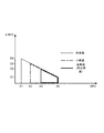
- FIG. 3 is an explanatory diagram of an example of a steady state map of the present embodiment.
- the steady state map is stored in the controller 8 in advance.
- the accelerator opening APO is set on the horizontal axis
- the change amount ⁇ APO of the accelerator opening is set on the vertical axis.
- the steady state regions at high vehicle speed (solid line), medium vehicle speed (one-dot chain line), and low vehicle speed (dotted line) are shown. It is shown.
- FIG. 3 at a high vehicle speed, a region surrounded by a solid line, that is, a region from the accelerator opening APO A3 and the change ⁇ APO D2 to the accelerator opening APO A4 and the change ⁇ APO D1 is in a steady state. It is shown that there is.
- the region surrounded by the alternate long and short dash line that is, the region from the accelerator opening APO A2 and the change ⁇ APO D3 to the accelerator opening APO A4 and the change ⁇ APO D1 is in a steady state. It is shown.
- the area surrounded by the dotted line that is, the area from the accelerator opening APO A1 and the change ⁇ APO D4 to the accelerator opening APO A4 and the change ⁇ APO D1 is in a steady state. Has been.
- the high vehicle speed shown in FIG. 3 is set equal to a predetermined vehicle speed, which is one of the conditions for determining whether the vehicle is in a steady state.
- the predetermined vehicle speed is 50 km / h, which is a high vehicle speed when traveling on a general road. Is set.
- the predetermined change amount which is another condition for determining whether the vehicle is in a steady state, is between D1 and D2 depending on the accelerator opening APO, and the predetermined opening is A4.
- the vehicle 100 travels at a substantially constant speed and there is no acceleration or deceleration. That is, it is determined that it is in a steady state.
- step S12 determines with it not being in a steady state
- step S18 the controller 8 immediately controls to the released state, once ends the processing of this flowchart, and returns to other processing.
- the disengaged state of the flywheel clutch CLfw indicates a non-power transmission state in which the flywheel clutch CLfw does not transmit power.
- step S12 the controller 8 acquires the current output Peng of the engine 1, and determines whether or not the output Peng is equal to or less than the first predetermined value P1.
- the output Peng of the engine 1 is acquired from an engine torque signal sent from the engine 1.
- the controller 8 may acquire the accelerator opening APO, the vehicle speed VSP, the current travel path inclination, and the like, and calculate the output Peng.
- step S13 When the output Peng is less than or equal to the first predetermined value P1, the process proceeds to step S13.
- the output Peng is larger than the first predetermined value P1, the process proceeds to step S15.
- the first predetermined value P1 in step S12 is a threshold value for determining whether the fuel consumption rate is larger than the output Peng in the relationship between the output Peng of the engine 1 and the fuel consumption rate in the steady state.
- the first predetermined value P1 is determined based on the fuel consumption rate map shown in FIG.
- FIG. 4 shows an example of the fuel consumption rate map of the present embodiment.
- the fuel consumption rate map is stored in the controller 8 in advance.
- the fuel consumption rate map shown in FIG. 4 is a map showing the characteristics of the engine 1 when the engine output is set on the horizontal axis and the fuel consumption rate is set on the vertical axis.
- the engine 1 that is an internal combustion engine has a characteristic that in a steady state, the fuel consumption rate with respect to the output Peng increases as the output Peng decreases.
- the engine 1 which is an internal combustion engine is designed so that the fuel consumption is best in the region of the load that is most often used during traveling, and the fuel consumption rate increases as the region deviates from this region.
- the output Peng of the engine 1 is low, the ratio of the power that rotates the engine 1 itself in the output Peng increases, and the fuel consumption rate increases.
- the threshold value of the region where the slope at which the fuel consumption rate increases with respect to the output Peng is steep is set as the first predetermined value P1. That is, in the area below the first predetermined value P1, the fuel consumption rate with respect to the output Peng is large. Therefore, operating in such a region in a steady state means that the fuel consumption rate is large and the energy efficiency is low.
- step S12 when the output Peng is equal to or less than the first predetermined value P1, the process proceeds to step S13, and the controller 8 engages the flywheel clutch CLfw. Then, the process of this flowchart is once complete
- the flywheel clutch CLfw When the flywheel clutch CLfw is engaged and the rotation of the flywheel 2 is increased by the engine 1, the flywheel 2 becomes a load on the engine 1 and the output Peng of the engine 1 increases. As a result, the operating state can be shifted to a region on the right side of the first predetermined value P1 in FIG. 4, that is, a region where the fuel consumption rate with respect to the output Peng of the engine 1 is small.
- the operating state of the engine 1 is set to a region where the fuel consumption rate is small, resulting in fuel consumption.
- the rate can be improved.
- step S15 the controller 8 determines whether or not the output Peng of the engine 1 is equal to or less than a second predetermined value P2.
- step S16 When the output Peng of the engine 1 is less than or equal to the second predetermined value P2, the process proceeds to step S16.
- the process of this flowchart is temporarily terminated and the process returns to another process.
- the second predetermined value P2 is determined based on the fuel consumption rate map shown in FIG.
- a threshold value in a region where the fuel consumption rate hardly changes with respect to the output Peng is set as the second predetermined value P2.
- the change in the fuel consumption rate with respect to the output Peng is small.
- the magnitude of the fuel consumption rate is proportional to the magnitude of the output Peng.
- the controller 8 controls the engagement capacity of the flywheel clutch CLfw according to the fuel consumption rate of the engine 1 by the control of the following steps S16 to S18.
- step S16 the controller 8 increases the engagement capacity of the flywheel clutch CLfw. That is, the controller 8 does not immediately set the flywheel clutch CLfw to the engaged state, but increases the engagement capacity of the flywheel clutch CLfw to place the flywheel clutch CLfw in the power transmission state and gradually increase the engagement capacity. Thus, the power that can be transmitted by the flywheel clutch CLfw is gradually increased.
- step S17 the controller 8 determines whether or not the fuel consumption rate has increased as a result of increasing the engagement capacity of the flywheel clutch CLfw.
- the process returns to step S16, and the increase in the engagement capacity of the flywheel clutch CLfw is continued. If it is determined that the fuel consumption rate has increased, the process proceeds to step S18.
- step S17 the controller 8 determines whether or not the fuel consumption rate has increased with reference to the equal fuel consumption rate line map shown in FIG.
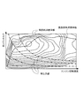
- FIG. 5 shows an example of an equal fuel consumption rate map of the present embodiment.
- the equal fuel consumption rate map is stored in the controller 8 in advance.
- the equal fuel consumption rate map shown in FIG. 5 shows the contour lines of the equal fuel consumption rate line (solid line), the best fuel consumption rate line (dotted line), and the equal output line in relation to the engine speed and the output of the engine 1. (One-dot chain line) is shown.
- the engine 1 which is an internal combustion engine has the characteristics as shown in FIG. 5, and the fuel consumption rate is the lowest in the vicinity of the best fuel consumption rate line.
- the area where the iso-output line corresponding to the current output of the engine 1 intersects with the best fuel consumption rate line is an operating state with the lowest fuel consumption rate at that output, and the fuel consumption increases as the distance from the best fuel consumption rate line increases The rate increases.
- FIG. 5 shows whether the controller 8 increases the engagement capacity of the flywheel clutch CLfw based on the current output Peng of the engine 1 and, as a result, the load on the engine 1 increases and the fuel consumption rate increases. Judged from the equal fuel consumption rate map.
- step S18 the controller 8 proceeds to step S18 to release the flywheel clutch CLfw, and then performs the processing of this flowchart. Is temporarily terminated, and the process returns to other processes. on the other hand. If it is determined that the fuel consumption rate has not increased, the process returns to step S16, and the increase in the engagement capacity of the flywheel clutch CLfw is continued.
- the engagement capacity of the flywheel clutch CLfw is increased and the flywheel 2 Increase the rotation of.
- the load of the engine 1 is reduced by releasing the flywheel clutch CLfw to suppress the increase in the fuel consumption rate.
- the flywheel clutch CLfw can be engaged when the vehicle 100 is in a steady state, and the rotation of the flywheel 2 can be increased. Thereby, the rotational speed difference at the time of fastening flywheel clutch CLfw at the time of regeneration can be made small.
- step S16 to S18 the engagement and disengagement of the flywheel clutch CLfw are controlled by increasing the fuel consumption rate, but the engagement and disengagement of the flywheel clutch CLfw may be controlled according to the rotational speed of the flywheel 2. .
- step S17 it is determined whether or not the flywheel rotation speed Nfw is equal to or higher than a predetermined rotation speed.
- the flywheel clutch CLfw is released and is less than the predetermined rotation. May control the flywheel clutch CLfw to be in a power transmission state.
- the rotation of the flywheel 2 is increased by controlling the power transmission state of the flywheel clutch CLfw by engaging and releasing the flywheel clutch CLfw so that the flywheel rotation speed Nfw maintains a predetermined rotation speed.
- the flywheel 2 is intermittently rotated and the flywheel clutch CLfw is not always in the power transmission state. If the flywheel clutch CLfw is always in the power transmission state, when acceleration is requested by the driver, not only will there be a time lag for the flywheel clutch CLfw to be in the released state, but also the flywheel until it is in the released state. 2 becomes inertia, and acceleration responsiveness is lowered.
- the flywheel clutch CLfw when the flywheel clutch CLfw is released and the driver requests acceleration from the steady state in the non-power transmission state, the flywheel clutch CLfw is set to the released state.
- the time lag (step S18 in FIG. 2) is less likely to occur, and the acceleration response is improved.
- the predetermined rotation speed is set to, for example, the flywheel rotation speed Nfw obtained by multiplying the rotation speed of the input shaft 3 in at that time by the reduction ratio of the reduction gears 11 and 12.
- Hysteresis may be set for the rotational speed of whether the flywheel clutch CLfw is in the power transmission state or in the release state.
- the CVT 3 serving as a transmission for shifting the rotation input from the engine 1 that is the power source of the vehicle 100 and outputting it to the drive wheels 6, the flywheel 2, the engine 1 and the CVT 3
- the engine clutch CL1 provided between the input shaft 3in and the flywheel clutch CLfw provided between the flywheel 2 and the input shaft 3in of the CVT 3, and when the vehicle 100 decelerates, the flywheel clutch CLfw is fastened to regenerate kinetic energy in the flywheel 2, and the flywheel regeneration system uses energy stored in the flywheel 2 for starting or accelerating the vehicle 100.
- the controller 8 is configured to rotate the flywheel 2 with the flywheel clutch CLfw in the power transmission state when the vehicle 100 is in a steady state.
- the flywheel 2 when the vehicle 100 is running and in a steady state, the flywheel 2 is rotated with the flywheel clutch CLfw in a power transmission state.
- the flywheel 2 when the kinetic energy is regenerated when the vehicle 100 decelerates, the rotational speed difference when the flywheel clutch CLfw is engaged can be reduced, and the flywheel clutch CLfw is engaged. Can be shortened, and the time for regenerating kinetic energy can be increased.
- the flywheel clutch CLfw is set in the power transmission state when the vehicle 100 is in a steady state, the rotation of the flywheel 2 is performed during steady running where the fuel consumption rate of the power source constituted by the engine 1 and the like is large. By increasing the engine load, the fuel consumption rate of the engine 1 can be reduced. Thus, when the vehicle 100 is in a steady state, the energy efficiency of the vehicle 100 can be improved by setting the flywheel clutch CLfw to the power transmission state.
- the controller 8 Since it is determined that the vehicle is in the steady state, it can be easily determined whether or not the vehicle 100 is in the steady state.
- the flywheel clutch CLfw is set in the power transmission state. Energy efficiency can be improved.
- the controller 8 puts the flywheel clutch CLfw into the released state, that is, the non-power transmission state, so that the fuel consumption
- the rotational speed of the flywheel 2 can be increased so that the rate does not increase, and the energy efficiency of the vehicle 100 can be improved.
- the controller 8 releases the flywheel clutch CLfw when the rotational speed of the flywheel 2 is equal to or higher than the predetermined rotational speed, and transmits power to the flywheel clutch CLfw when the rotational speed of the flywheel 2 is lower than the predetermined rotational speed. Therefore, the flywheel clutch CLfw is not always in the power transmission state. For example, when the flywheel clutch CLfw is in the released state and acceleration is requested by the driver in the non-power transmission state, A time lag for causing the wheel clutch CLfw to be in a released state is reduced, and acceleration response is improved.
- the controller 8 controls the power transmission state of the flywheel clutch CLfw so that the flywheel rotational speed Nfw maintains a predetermined rotational speed.
- the flywheel clutch CLfw when the vehicle 100 is no longer in a steady state, the flywheel clutch CLfw is controlled to be immediately released (steps S11 and S18 in FIG. 2).
- the flywheel clutch CLfw it is also conceivable to place the flywheel clutch CLfw in the power transmission state not only in the steady state but also in the slow acceleration state.
- the flywheel clutch CLfw when the vehicle 100 is in a steady state, the flywheel clutch CLfw is set in a power transmission state, and when the vehicle 100 is not in a steady state, the flywheel clutch CLfw is set in a released state, whereby acceleration from the driver is achieved. Since it is not influenced by the load of the flywheel 2 when requested, the driver does not feel uncomfortable.
- the power transmission of the flywheel clutch CLfw is performed so that the flywheel clutch is in the power transmission state when the vehicle 100 is in a steady state, or the rotation speed of the flywheel 2 is maintained at a predetermined rotation speed. Configured to control the state. Further, when the rotational speed on the output side (flywheel 2 side) of the flywheel clutch CLfw is higher than the rotational speed on the input side (drive wheel 6 side), control is performed so as to prohibit the engagement of the flywheel clutch CLfw. May be. Thereby, it can prevent that the rotational speed of the flywheel 2 falls, and can maintain the rotational speed of the flywheel 2 in a high state.
- the vehicle 100 includes only the engine 1 as a power source.
- the vehicle 100 may include the engine 1 and a motor as power sources, or may include only a motor instead of the engine 1. Good.
- the power source is a motor
- the engagement and disengagement of the flywheel clutch CLfw may be controlled based on the power consumption of the motor instead of the fuel consumption rate of the engine 1.
- the vehicle 100 includes the CVT 3 as a transmission
- the type of the transmission is not limited to this, and may include a stepped transmission instead of the CVT 3.
Landscapes
- Engineering & Computer Science (AREA)
- Chemical & Material Sciences (AREA)
- Combustion & Propulsion (AREA)
- Transportation (AREA)
- Mechanical Engineering (AREA)
- Arrangement Or Mounting Of Propulsion Units For Vehicles (AREA)
- Hydraulic Clutches, Magnetic Clutches, Fluid Clutches, And Fluid Joints (AREA)
Abstract
車両の動力源から入力される回転を変速して駆動輪に出力する変速機と、フライホイールと、フライホイールと変速機の入力軸との間に設けられるフライホイールクラッチと、を備え、車両の減速中に、フライホイールクラッチを締結してフライホイールに運動エネルギーを回生し、フライホイールのエネルギーを車両の発進又は加速に用いるフライホイール回生システムであって、車両が定常状態であるときに、フライホイールクラッチを動力伝達状態として、フライホイールを回転させる。
Description
本発明は、車両の運動エネルギーをフライホイールで回生するフライホイール回生技術に関する。
車両の燃費・電費を向上させるには、減速時に車両が持つ運動エネルギーを電気的又は機械的に回生し、回生した運動エネルギーを発進時や加速時に利用するのが有効である。
JP2012-516417Aには、変速機の入力軸にクラッチによって断続可能なフライホイールを設け、減速時に当該クラッチを締結して駆動輪から入力される回転でフライホイールを回転させ、車両の運動エネルギーをフライホイールの運動エネルギーに変換するフライホイール回生システムが開示されている。
このようなフライホイール回生システムにおいては、クラッチを解放すれば回生した運動エネルギーをフライホイールに保存することができ、また、発進時や加速時にクラッチを締結すれば、フライホイールに保存された運動エネルギーを放出させ、車両の発進や加速に利用することができる。
JP2012-516417Aに開示されている構成のフライホイール回生システムでは、フライホイールの回生を行うときにクラッチを締結するが、クラッチ締結時の回転速度差が大きい場合、短時間でクラッチを締結完了させると、クラッチに蓄積される発熱量のピーク値が高くなりクラッチの耐久性が低下する。これを抑制すべくクラッチの締結が完了するまでの時間を長くする。また、クラッチ締結時の回転速度差が大きいと、クラッチの締結に際して蓄積される発熱量が大きくなり耐久性が低下する。
特に、フライホイールのクラッチを解放した後は、フライホイールの回転軸のフリクションや空気抵抗等によって、フライホイールの回転速度が徐々に低下する。そのため、フライホイールへの回生が長期間行われない場合は、フライホイールの回転速度が低下し、クラッチ締結時の回転速度差が大きくなる。クラッチ締結時の回転速度差が大きい場合はクラッチの締結が完了するまでの時間が長くなり、クラッチの締結完了後において回生を行う時間が削減される。このために、運動エネルギーが十分に回生できなくなる。
本発明は、このような問題に鑑みてなされたもので、フライホイールの回転の低下を抑制して、クラッチ締結時の回転速度差を抑制できるフライホイール回生システムを提供することを目的とする。
本発明のある態様によれば、車両の動力源から入力される回転を変速して駆動輪に出力する変速機と、フライホイールと、フライホイールと変速機の入力軸との間に設けられるフライホイールクラッチと、を備え、車両の減速中に、フライホイールクラッチを締結してフライホイールに運動エネルギーを回生し、フライホイールのエネルギーを車両の発進又は加速に用いるフライホイール回生システムであって、車両が定常状態であるときに、フライホイールクラッチを動力伝達状態として、フライホイールを回転させるフライホイール制御手段、を備えることを特徴とする。
上記態様によれば、車両が定常状態であるときに、フライホイールクラッチを動力伝達状態としてフライホイールを回転させるので、その後、車両が減速するとき運動エネルギーを回生する場合には、既にフライホイールが回転されていることでフライホイールクラッチを締結するときの回転速度差が小さくなり、フライホイールクラッチの締結が完了するまでの時間が短縮される。これにより、運動エネルギーの回生を行う時間を大きくすることができるので、フライホイールに回生できるエネルギーが大きくなり、エネルギー効率を向上することができる。
以下、図面を参照して本発明の実施形態について説明する。
図1は、本発明の実施形態に係るフライホイール回生システムを備える車両100の全体構成を示す。
車両100は、動力源としてのエンジン1と、エネルギーを回生するフライホイール2と、エンジン1の出力回転を無段階に変速する無段変速機(以下、CVT)3と、CVT3の出力回転を減速する終減速装置4と、差動装置5と、左右の駆動輪6と、油圧回路7と、コントローラ8とを備える。
エンジン1とCVT3の入力軸3inとの間には、エンジンクラッチCL1が設けられる。エンジンクラッチCL1は、供給される油圧によって締結容量を制御可能な油圧式クラッチであり、エンジンクラッチCL1を締結状態としたときに、エンジン1の駆動力がCVT3へと伝達される。
CVT3の入力軸3inには、入力軸3inの回転により駆動され油圧を発生するオイルポンプ10が接続される。オイルポンプ10は、例えばギヤポンプやベーンポンプにより構成される。オイルポンプ10が発生した油圧は後述する油圧回路7を介して、CVT3、エンジンクラッチCL1、後述する発進クラッチCL2等に供給される。
CVT3の入力軸3inには、さらに、一対の減速ギヤ列11、12を介してフライホイール2が接続される。フライホイール2は、回転可能な円筒体又は円盤形状の金属体が容器内に収装されて構成される。容器内は、金属体が回転するときの空気抵抗による影響(風損とも呼ぶ)を低減するために、真空状態又は減圧されている。
減速ギヤ列11と減速ギヤ列12との間にはフライホイールクラッチCLfwが設けられる。フライホイールクラッチCLfwは、供給される油圧によって締結容量を制御可能な油圧式クラッチである。フライホイールクラッチCLfwは、入力軸3inの回転にかかわらず油圧を供給可能な油圧元によって締結容量が制御される。具体的には、オイルポンプ10とは異なり、電動モータにより駆動される油圧ポンプにより発生された油圧がフライホイールクラッチCLfwに供給される。フライホイールクラッチCLfwは、電動モータにより駆動される油圧ポンプではなく、電動のアクチュエータによって締結容量が制御されてもよい。
CVT3と終減速装置4の間には、発進時に締結され、CVT3を介して入力されるエンジン1又はフライホイール2からの回転を終減速装置4に伝達する発進クラッチCL2が設けられる。発進クラッチCL2は、供給される油圧によって締結容量を制御可能な油圧式クラッチである。図1に示す例では、CVT3と終減速装置4との間には発進クラッチCL2しか設けられていないが、CVT3と終減速装置4の間に有段変速機を設ける構成であってもよく、この場合は、有段変速機の1速を実現するブレーキ又はクラッチが発進クラッチCL2となる。発進クラッチCL2はエンジン1とCVT3との間に備えられてもよい。また、入力軸3inにトルクコンバータを備えてもよい。
油圧回路7は、後述するコントローラ8からの信号を受けて動作するソレノイド弁等で構成され、CVT3、エンジンクラッチCL1、発進クラッチCL2及びオイルポンプ10と油路を介して接続される。油圧回路7は、オイルポンプ10で発生した油圧を元圧として、CVT3のプーリ、エンジンクラッチCL1及び発進クラッチCL2で必要とされる油圧を生成し、生成した油圧をCVT3のプーリ、エンジンクラッチCL1及び発進クラッチCL2に供給する。
ブレーキ14は、ブレーキペダル15とマスターシリンダ16とが機構的に独立している電子制御式ブレーキである。運転者がブレーキペダル15を踏み込むと、ブレーキアクチュエータ17がマスターシリンダ16のピストンを変位させ、運転者がブレーキペダル15を踏み込む力、すなわち要求減速度に応じた油圧がブレーキ14に供給され、ブレーキ14によって要求減速度に応じた制動力が発生する。図示は省略するが、ブレーキ14は従動輪にも設けられる。
コントローラ8は、CPU、RAM、入出力インターフェース等で構成される。コントローラ8には、エンジン1のトルクセンサ28、エンジン1の回転速度を検出する回転速度センサ21、CVT3の入力軸3inの回転速度(入力軸回転速度Nin)を検出する回転速度センサ22、フライホイール2の回転速度Nfwを検出する回転速度センサ23、車速VSPを検出する車速センサ24、アクセルペダル25の開度APOを検出するアクセル開度センサ26、運転者がブレーキペダル15の踏む力を検出するブレーキセンサ27等からの信号が入力される。
コントローラ8は、入力される信号に基づき各種演算を行い、CVT3の変速、各クラッチCL1、CL2、CLfwの締結・解放、ブレーキアクチュエータ17を制御する。特に、運転者がブレーキペダル15を踏み込み、車両100が減速するときは、コントローラ8は、フライホイールクラッチCLfwを締結し、駆動輪6から入力される回転を減速ギヤ列11、12により増速してフライホイール2を回転させ、車両100が持つ運動エネルギーをフライホイール2の運動エネルギーに変換することで、車両100の運動エネルギーを回生する。
このとき、後述するようにCVT3の変速比をLow側にダウンシフトすることにより、駆動輪6の回転速度を増速してフライホイール2に入力することができ、フライホイール2の回転速度、すなわち、保存される運動エネルギーの大きさを高めることができる。
回生中、コントローラ8は、運転者の減速度要求に応じた制動力(回生ブレーキ)が得られるようフライホイールクラッチCLfwの締結容量を制御する。フライホイールクラッチCLfwを締結する前で回生ブレーキを発生させられない場合や回生ブレーキのみでは運転者の減速度要求を満たせない場合は、コントローラ8は、ブレーキアクチュエータ17を動作させてブレーキ14の制動力を増大させ、運転者の減速度要求に応じた制動力が得られるようにする。
回生された運動エネルギーは、フライホイールクラッチCLfwを解放することによってフライホイール2の回転として保存できる。フライホイール2に運動エネルギーが保存されている状態でフライホイールクラッチCLfwを締結することで、フライホイール2に保存されている運動エネルギーが入力軸3inに伝達され、車両100の発進又は加速のエネルギーとすることができる。
特に、フライホイール2の質量や減速ギヤ列11、12の減速比を適切に選定することにより、フライホイール2が十分に回転している状態で、重量物である車両100を発進させるのに十分なエネルギーを保存することができる。
このように、車両100が減速する時に、コントローラ8がフライホイールクラッチCLfwを締結し、車両100の運動エネルギーが回生される。
ここで、フライホイールクラッチCLfwを締結するときに、フライホイールクラッチCLfwにおける入力側と出力側との回転速度差が大きい場合は、フライホイールクラッチCLfwの締結を開始してから回転速度差が解消して締結が完了するまでの時間が長くなる。これは、減速中であっていずれ停車状態となる車両100において、フライホイール2が回生を行う時間が短くなることを意味する。
また、フライホイールクラッチCLfwの締結が完了するまでの時間が長くなると、フライホイールクラッチCLfwの発熱量が大きくなり、フライホイールクラッチCLfwの耐久性や寿命が低下するおそれがある。
このような理由から、フライホイールクラッチCLfwを締結するとき、入力側と出力側との回転速度差が小さいことが望ましい。
一方で、フライホイールクラッチCLfwを解放した後、特にフライホイール2のエネルギーを放出した後は、フライホイール2の回転軸のフリクションやケースの中に僅かに残留する空気の風損等によって、フライホイール回転速度Nfwが次第に低下する。そのため、フライホイール2への回生が長期間行われなかった場合は、フライホイール回転速度Nfwが低下し、フライホイールクラッチCLfwを締結するときの回転速度差が大きくなる。
そこで、コントローラ8は、以下に説明するフライホイール制御を行い、回生を行うとき以外にもフライホイール2の回転を上昇させておくことで、フライホイールクラッチCLfwを締結するときの回転速度差を小さくするように構成した。
図2は、本発明の実施形態のコントローラ8が実行するフライホイール制御を示すフローチャートである。図2に示すフローチャートは、コントローラ8における他の処理と並列して、所定の周期(例えば10ms毎)に実行される。
ステップS11において、コントローラ8は、現在の車両100の運転状態が定常状態であるか否かを判定する。定常状態とは、車両100が略一定速度で走行し、加速や減速がない走行状態を言う。より具体的には、車速VSPが所定車速未満、アクセル開度APOの変化量ΔAPOが所定変化量未満、かつ、アクセル開度APOが所定開度未満である場合に、コントローラ8は車両100が定常状態であると判断する。
定常状態か否かは、図3に示す定常状態マップにより判定される。
図3は、本実施形態の定常状態マップの一例の説明図である。定常状態マップはコントローラ8に予め記憶されている。図3において、横軸にアクセル開度APO、縦軸にアクセル開度の変化量ΔAPOが設定され、高車速(実線)、中車速(一点鎖線)及び低車速(点線)における定常状態の領域が示されている。
図3において、高車速では、実線で囲まれた領域、すなわち、アクセル開度APOがA3及び変化量ΔAPOがD2から、アクセル開度APOがA4及び変化量ΔAPOがD1までの領域が定常状態であることが示されている。
中車速では、一点鎖線で囲まれた領域、すなわち、アクセル開度APOがA2及び変化量ΔAPOがD3から、アクセル開度APOがA4及び変化量ΔAPOがD1までの領域が定常状態であることが示されている。
低車速では、点線で囲まれた領域、すなわち、アクセル開度APOがA1及び変化量ΔAPOがD4から、アクセル開度APOがA4及び変化量ΔAPOがD1までの領域が定常状態であることが示されている。
また、図3に示す高車速は、定常状態であるか判定する条件の一つである所定車速と等しく設定され、例えば所定車速は、一般道路を走行するときに高車速となる50km/hに設定される。高車速においては、定常状態であるかを判定する他の条件である所定変化量は、アクセル開度APOに応じてD1からD2の間となり、所定開度はA4となる。
このように、ある車速VSPに対してアクセル開度APOと変化量ΔAPOとが図3に示すような領域である場合は、車両100が略一定速度で走行し、加速や減速がない走行状態、すなわち、定常状態であると判定される。
定常状態と判定した場合は、ステップS12に移行する。定常状態でないと判定した場合は、ステップS18に移行する。この場合は、コントローラ8は、フライホイールクラッチCLfwが締結されている場合は直ちに解放状態に制御し、本フローチャートの処理を一旦終了して、他の処理に戻る。フライホイールクラッチCLfwが解放状態とは、フライホイールクラッチCLfwが動力を伝達しない非動力伝達状態であることを示す。
ステップS12では、コントローラ8は、現在のエンジン1の出力Pengを取得し、出力Pengが第1所定値P1以下であるか否かを判定する。エンジン1の出力Pengは、エンジン1から送られるエンジントルク信号により取得する。または、コントローラ8が、アクセル開度APO、車速VSP、現在の走行路の傾斜等を取得し、出力Pengを算出してもよい。
出力Pengが第1所定値P1以下である場合はステップS13に移行する。出力Pengが第1所定値P1より大きい場合はステップS15に移行する。
ステップS12における第1所定値P1は、定常状態でのエンジン1の出力Pengと燃料消費率との関係において、出力Pengに対して燃料消費率が大きい状態であるかを判定する閾値である。
第1所定値P1は、図4に示す燃料消費率マップに基づき決定される。
図4は、本実施形態の燃料消費率マップの一例を示す。燃料消費率マップはコントローラ8に予め記憶されている。図4に示す燃料消費率マップは、横軸にエンジン出力、縦軸に燃料消費率をそれぞれ設定したときのエンジン1の特性を示すマップである。一般的に、内燃機関であるエンジン1は、定常状態において、出力Pengが小さいほど出力Pengに対する燃料消費率が大きくなる特性を有する。
内燃機関であるエンジン1は、走行時に最もよく使われる負荷の領域が最も燃費がよくなるように設計されており、この領域から外れるに従って燃料消費率が大きくなる。定常走行においては、エンジン1の出力Pengが低い場合は、出力Pengのうちエンジン1自体を回転させる力が占める割合が大きくなり、燃料消費率が増大する。
このように、出力Pengに対する燃料消費率が増大する傾きが急となる領域の閾値を第1所定値P1として設定する。すなわち、第1所定値P1以下の領域では、出力Pengに対する燃料消費率が大きい領域である。そのため、定常状態においてこのような領域で運転を行うことは、燃料消費率が大きく、エネルギー効率が低いことを意味する。
ステップS12において、出力Pengが第1所定値P1以下である場合は、ステップS13に移行して、コントローラ8は、フライホイールクラッチCLfwを締結させる。その後、本フローチャートの処理を一旦終了し、他の処理に戻る。
フライホイールクラッチCLfwを締結させて、エンジン1によりフライホイール2の回転を上昇させることで、フライホイール2がエンジン1の負荷となり、エンジン1の出力Pengが増大する。この結果、運転状態を、図4における第1所定値P1よりも右側の領域、すなわちエンジン1の出力Pengに対する燃料消費率が小さい領域へと遷移させることができる。
このように制御することにより、フライホイール2の負荷による出力Pengが増大することによって燃料が消費されたとしても、エンジン1の運転状態を燃料消費率が小さい領域とすることで、結果として燃料消費率を改善できる。
一方、ステップS12において、出力Pengが第1所定値P1より大きい場合は、ステップS15に移行する。ステップS15では、コントローラ8は、エンジン1の出力Pengが第2所定値P2以下であるか否かを判定する。
エンジン1の出力Pengが第2所定値P2以下である場合はステップS16に移行する。出力Pengが第2所定値P2よりも大きい場合は、本フローチャートの処理を一旦終了し、他の処理に戻る。
第2所定値P2についても、第1所定値P1と同様に、図4に示す燃料消費率マップに基づき決定される。定常状態において、出力Pengに対して燃料消費率がほぼ変化しなくなる領域の閾値を、第2所定値P2として設定する。第2所定値P2よりも出力Pengが大きい領域では、出力Pengに対する燃料消費率の変化は小さい。言い換えると、第2所定値P2よりも大きな領域では、燃料消費率の大きさが出力Pengの大きさに比例する。
そのような場合には、フライホイールクラッチCLfwを締結してフライホイール2の回転の上昇行っても、エンジン1の負荷の増大により燃料消費率は減少しないので、フライホイール2の回転の上昇は行わない。
一方で、第2所定値P2以下の領域では、出力Pengを増大させることで燃料消費率を減少させる余地がある。そこで、この場合は、コントローラ8は、次のステップS16からS18の制御によって、エンジン1の燃料消費率に応じてフライホイールクラッチCLfwの締結容量を制御する。
まず、ステップS16において、コントローラ8は、フライホイールクラッチCLfwの締結容量を増加させる。すなわち、コントローラ8は、フライホイールクラッチCLfwを直ちに締結状態とするのではなく、フライホイールクラッチCLfwの締結容量を増加させることでフライホイールクラッチCLfwを動力伝達状態とし、締結容量を徐々に増加させることで、フライホイールクラッチCLfwが伝達可能な動力を徐々に増加させる。
次に、ステップS17において、コントローラ8は、フライホイールクラッチCLfwの締結容量を増加させた結果、燃料消費率が増大したか否かを判定する。燃料消費率が増大していない場合はステップS16に戻り、フライホイールクラッチCLfwの締結容量の増加を継続する。燃料消費率が増大したと判定した場合は、ステップS18に移行する。
ステップS17において、コントローラ8は、燃料消費率が増大したか否かを、図5に示す等燃料消費率線マップを参照して判定する。
図5は、本実施形態の等燃料消費率マップの一例を示す。等燃料消費率マップはコントローラ8に予め記憶されている。図5に示す等燃料消費率マップには、エンジン回転速度とエンジン1の出力との関係において、等燃料消費率線(実線)の等高線と、最良燃料消費率線(点線)と、等出力線(一点鎖線)とが示されている。
内燃機関であるエンジン1は、図5のような特性を有しており、最良燃料消費率線付近が最も燃料消費率が少ない運転状態となる。また、現在のエンジン1の出力に対応する等出力線と最良燃料消費率線とが交わる付近が、その出力での最も燃料消費率が少ない運転状態となり、最良燃料消費率線から離れるに従って燃料消費率は増大する。
コントローラ8は、現在のエンジン1の出力Pengに基づき、フライホイールクラッチCLfwの締結容量を増加させた結果、エンジン1の負荷が増大して燃料消費率が増大したか否かを、図5に示す等燃料消費率マップから判定する。
コントローラ8は、フライホイールクラッチCLfwの締結容量を増加させた結果、燃料消費率が増大したと判定した場合は、ステップS18に移行して、フライホイールクラッチCLfwを解放状態としてから、本フローチャートの処理を一旦終了し、他の処理に戻る。一方。燃料消費率が増大していないと判定した場合は、ステップS16に戻り、フライホイールクラッチCLfwの締結容量の増加を継続する。
ステップS16からS18の処理により、エンジン1の出力Pengが第1所定値P1よりも大きく、第2所定値P2以下である場合には、フライホイールクラッチCLfwの締結容量を増加させて、フライホイール2の回転を上昇させる。このとき、フライホイール2の回転の上昇によってエンジン1の燃料消費率が増大した場合は、フライホイールクラッチCLfwを解放状態とすることでエンジン1の負荷を減少させて、燃料消費率の増大を抑える。
このように、図2のフローチャートに示すフライホイール制御を行うことによって、車両100が定常状態のときにフライホイールクラッチCLfwを締結して、フライホイール2の回転を上昇させておくことができる。これにより、回生時にフライホイールクラッチCLfwを締結するときの回転速度差を小さくすることができる。
ステップS16からS18の処理では、燃料消費率の増大によりフライホイールクラッチCLfwの締結及び解放を制御したが、フライホイール2の回転速度に応じてフライホイールクラッチCLfwの締結及び解放を制御してもよい。
すなわち、ステップS17において、フライホイール回転速度Nfwが所定回転速度以上であるか否かを判定し、所定回転速度以上となった場合にフライホイールクラッチCLfwを解放状態とし、所定回転未満である場合にはフライホイールクラッチCLfwを動力伝達状態とするように制御してもよい。
このように、フライホイール回転速度Nfwが所定回転速度を維持するようにフライホイールクラッチCLfwを締結及び解放することでフライホイールクラッチCLfwの動力伝達状態を制御することによって、フライホイール2の回転を上昇させておくことができると共に、フライホイール2を間歇的に回転させ、フライホイールクラッチCLfwが常に動力伝達状態となることがない。フライホイールクラッチCLfwを常に動力伝達状態とすると、運転者により加速が要求されたとき、フライホイールクラッチCLfwを解放状態とするためのタイムラグが生じるだけでなく、解放状態とするまでの間はフライホイール2がイナーシャとなって、加速応答性を低下させることになる。しかしながら、本実施形態の構成により、例えばフライホイールクラッチCLfwが解放状態とされて非動力伝達状態における定常状態から運転者により加速が要求されたときに、フライホイールクラッチCLfwを解放状態とするためのタイムラグ(図2のステップS18)が生じることが少なくなり加速応答性が改善される。
所定回転速度は、例えばその時点での入力軸3inの回転速度に減速ギヤ11、12の減速比を掛け合わせたフライホイール回転速度Nfwに設定する。フライホイールクラッチCLfwを動力伝達状態とするか解放状態とするかの回転速度にヒステリシスを設定してもよい。
以上のように、本実施形態では、車両100の動力源であるエンジン1から入力される回転を変速して駆動輪6に出力する変速機としてのCVT3と、フライホイール2と、エンジン1とCVT3の入力軸3inとの間に設けられるエンジンクラッチCL1と、フライホイール2とCVT3の入力軸3inとの間に設けられるフライホイールクラッチCLfwと、を備え、車両100が減速するときに、フライホイールクラッチCLfwを締結してフライホイール2に運動エネルギーを回生し、フライホイール2に保存されたエネルギーを車両100の発進又は加速に用いるフライホイール回生システムとして構成される。
このように構成されたフライホイール回生システムにおいて、コントローラ8は、車両100が定常状態であるときに、フライホイールクラッチCLfwを動力伝達状態として、フライホイール2を回転させるように構成した。
本実施形態では、このような構成によって、車両100が走行中でかつ定常状態のときに、フライホイールクラッチCLfwを動力伝達状態としてフライホイール2を回転させる。フライホイール2が回転していることで、車両100が減速するとき運動エネルギーを回生する場合に、フライホイールクラッチCLfwを締結するときの回転速度差を小さくすることができ、フライホイールクラッチCLfwの締結が完了するまでの時間を短縮できて、運動エネルギーの回生を行う時間を大きくすることができる。
またさらに、車両100が定常状態であるときにフライホイールクラッチCLfwを動力伝達状態にするので、エンジン1等から構成される動力源の燃料消費率が大きな定常走行のときに、フライホイール2の回転を上昇させることでエンジン1の負荷を増大させることで、エンジン1の燃料消費率を小さくすることができる。このように、車両100が定常状態であるときに、フライホイールクラッチCLfwを動力伝達状態とすることで、車両100のエネルギー効率を向上することができる。
また、コントローラ8は、車速VSPが所定車速未満であり、アクセル開度APOの変化量ΔAPOが所定変化量未満であり、かつ、アクセル開度APOが所定開度未満であるときに、車両100が定常状態であると判定するので、容易に車両100が定常状態であるか否かを判定することができ、定常状態であるときに、フライホイールクラッチCLfwを動力伝達状態とすることで、車両100のエネルギー効率を向上することができる。
また、コントローラ8は、フライホイールクラッチCLfwを動力伝達状態としたときに、エンジン1の燃料消費率が増大する場合は、フライホイールクラッチCLfwを解放状態、すなわち非動力伝達状態とするので、燃料消費率が増大しないようにフライホイール2の回転速度を上昇させることができ、車両100のエネルギー効率を向上することができる。
また、コントローラ8は、フライホイール2の回転速度が所定回転速度以上のときにフライホイールクラッチCLfwを解放状態とし、フライホイール2の回転速度が所定回転速度未満のときにフライホイールクラッチCLfwを動力伝達状態とするので、フライホイールクラッチCLfwが常に動力伝達状態となることがなく、例えばフライホイールクラッチCLfwが解放状態とされて、非動力伝達状態における運転者により加速が要求されたときにも、フライホイールクラッチCLfwを解放状態とするためのタイムラグが生じることが少なくなり、加速応答性が改善される。
また、コントローラ8は、フライホイール回転速度Nfwが所定回転速度を維持するようにフライホイールクラッチCLfwの動力伝達状態を制御する。これにより、車両100が減速するとき運動エネルギーを回生する場合に、フライホイール2が所定回転速度に維持されることで、フライホイールクラッチCLfwを締結するときの回転速度差を小さくすることができ、フライホイールクラッチCLfwの締結が完了するまでの時間を短縮できて、運動エネルギーの回生を行う時間を大きくすることができる。
以上、本発明の実施形態について説明したが、上記実施形態は本発明の適用例の一部を示したものに過ぎず、本発明の技術的範囲を上記実施形態の具体的構成に限定する趣旨ではない。
上記実施形態では、車両100が定常状態ではなくなったときに、直ちにフライホイールクラッチCLfwを解放状態とするように制御している(図2のステップS11及びステップS18)。一方で、定常状態ではなく、緩加速状態のときにもフライホイールクラッチCLfwを動力伝達状態とすることも考えられる。
しかしながら、このように制御した場合は、緩加速状態にて運転者から加速が要求された場合に、負荷となるフライホイール2を切り離す必要があり、緩加速中にフライホイールクラッチCLfwの解法を行う。緩加速が要求されているときにフライホイールクラッチCLfwを解放状態とすると、フライホイール2の負荷の減少によりフライホイール2を回転させていたエンジン1の駆動力分が車両100へと伝達されることになり、車両100の加速度が急変して過剰な駆動力による加速となり、運転者に違和感を与える。
これを防ぐために、運転者から加速が要求された場合に、フライホイールクラッチCLfwの締結容量を徐々に減少させて緩やかに解放状態へと制御することも考えられるが、このような制御では、運転者の加速要求に対して車両100が十分な加速度を得られなくなり、運転者に違和感を与える。
本実施形態では、車両100が定常状態のときにフライホイールクラッチCLfwを動力伝達状態とし、車両100が定常状態ではなくなった場合にフライホイールクラッチCLfwを解放状態とすることにより、運転者から加速が要求された場合に、フライホイール2の負荷による影響を受けないので、運転者に違和感を与えることがない。
また、上記実施形態では、車両100が定常状態であるときにフライホイールクラッチを動力伝達状態とする、又は、フライホイール2の回転速度が所定回転速度を維持するようにフライホイールクラッチCLfwの動力伝達状態を制御するように構成した。さらに、フライホイールクラッチCLfwの出力側(フライホイール2側)の回転速度が入力側(駆動輪6側)の回転速度よりも高い場合には、フライホイールクラッチCLfwの締結を禁止するように制御してもよい。これによりフライホイール2の回転速度が低下することを防止して、フライホイール2の回転速度を高い状態に維持することができる。
また、上記実施形態では、車両100は動力源としてエンジン1のみを備えているが、動力源としてエンジン1とモータとを備えていてもよいし、エンジン1に代えてモータのみを備えていてもよい。動力源をモータとした場合は、エンジン1の燃料消費率の代わりにモータの消費電力に基づいて、フライホイールクラッチCLfwの締結及び解放を制御してもよい。
また、車両100は変速機としてCVT3を備えているが、変速機の種類はこれに限定されず、CVT3に代えて有段変速機を備えていてもよい。
本願は、2013年8月8日に日本国特許庁に出願された特願2013-165284に基づく優先権を主張する。これらの出願のすべての内容は参照により本明細書に組み込まれる。
Claims (6)
- 車両の動力源から入力される回転を変速して駆動輪に出力する変速機と、
フライホイールと、
前記フライホイールと前記変速機の入力軸との間に設けられるフライホイールクラッチと、を備え、
前記車両の減速中に、前記フライホイールクラッチを締結して前記フライホイールに運動エネルギーを回生し、前記フライホイールのエネルギーを前記車両の発進又は加速に用いるフライホイール回生システムであって、
前記車両が定常状態であるときに、前記フライホイールクラッチを動力伝達状態として、前記フライホイールを回転させるフライホイール制御手段を備える
フライホイール回生システム。 - 請求項1に記載のフライホイール回生システムであって、
前記フライホイール制御手段は、車速が所定車速未満であり、アクセル開度の変化量が所定変化量未満であり、かつ、アクセル開度が所定開度未満であるときに、前記車両が定常状態であると判定する
フライホイール回生システム。 - 請求項1又は2に記載のフライホイール回生システムであって、
前記フライホイール制御手段は、前記フライホイールクラッチを動力伝達状態としたときに、前記動力源の燃料消費率が増大する場合は、前記フライホイールクラッチを解放状態とする
フライホイール回生システム。 - 請求項1から3のいずれか一つに記載のフライホイール回生システムであって、
前記フライホイール制御手段は、前記フライホイールの回転速度が所定回転速度以上のときに前記フライホイールクラッチを解放状態とし、前記フライホイールの回転速度が所定回転速度未満のときに前記フライホイールクラッチを動力伝達状態とする
フライホイール回生システム。 - 車両の動力源から入力される回転を変速して駆動輪に出力する変速機と、
フライホイールと、
前記フライホイールと前記変速機の入力軸との間に設けられるフライホイールクラッチと、を備え、
前記車両の減速中に、前記フライホイールクラッチを締結して前記フライホイールに運動エネルギーを回生し、前記フライホイールのエネルギーを前記車両の発進又は加速に用いるフライホイール回生システムであって、
前記フライホイールの回転速度が所定回転速度を維持するように前記フライホイールクラッチの動力伝達状態を制御するフライホイール回転速度制御手段を備える
フライホイール回生システム。 - 車両の動力源から入力される回転を変速して駆動輪に出力する変速機と、フライホイールと、前記フライホイールと前記変速機の入力軸との間に設けられるフライホイールクラッチと、を備え、前記車両の減速中に、前記フライホイールクラッチを締結して前記フライホイールに運動エネルギーを回生し、前記フライホイールのエネルギーを前記車両の発進又は加速に用いるフライホイール回生システムの制御方法であって、
前記車両が定常状態であるときに、前記フライホイールクラッチを動力伝達状態として、前記フライホイールを回転させる
ことを特徴とするフライホイール回生システムの制御方法。
Applications Claiming Priority (2)
| Application Number | Priority Date | Filing Date | Title |
|---|---|---|---|
| JP2013-165284 | 2013-08-08 | ||
| JP2013165284A JP2015033891A (ja) | 2013-08-08 | 2013-08-08 | フライホイール回生システム及びその制御方法 |
Publications (1)
| Publication Number | Publication Date |
|---|---|
| WO2015019789A1 true WO2015019789A1 (ja) | 2015-02-12 |
Family
ID=52461128
Family Applications (1)
| Application Number | Title | Priority Date | Filing Date |
|---|---|---|---|
| PCT/JP2014/068474 Ceased WO2015019789A1 (ja) | 2013-08-08 | 2014-07-10 | フライホイール回生システム及びその制御方法 |
Country Status (2)
| Country | Link |
|---|---|
| JP (1) | JP2015033891A (ja) |
| WO (1) | WO2015019789A1 (ja) |
Cited By (2)
| Publication number | Priority date | Publication date | Assignee | Title |
|---|---|---|---|---|
| CN108136923A (zh) * | 2015-05-28 | 2018-06-08 | 久益环球朗维尤运营有限公司 | 用于在采矿机械中存储能量的系统、方法和设备 |
| GB2559345A (en) * | 2017-01-31 | 2018-08-08 | Flybrid Automotive Ltd | An energy storage and recovery system |
Citations (4)
| Publication number | Priority date | Publication date | Assignee | Title |
|---|---|---|---|---|
| JP2001352606A (ja) * | 2000-06-09 | 2001-12-21 | Takayuki Miyao | フライホイール・電池・エネルギー蓄積駆動方法 |
| JP2003165361A (ja) * | 2001-11-29 | 2003-06-10 | Toyota Motor Corp | 車両の制御装置 |
| JP2007315447A (ja) * | 2006-05-24 | 2007-12-06 | Toyota Motor Corp | 車両用動力装置およびその制御装置 |
| JP2010270796A (ja) * | 2009-05-19 | 2010-12-02 | Toyota Motor Corp | フライホイール付き動力伝達装置 |
-
2013
- 2013-08-08 JP JP2013165284A patent/JP2015033891A/ja active Pending
-
2014
- 2014-07-10 WO PCT/JP2014/068474 patent/WO2015019789A1/ja not_active Ceased
Patent Citations (4)
| Publication number | Priority date | Publication date | Assignee | Title |
|---|---|---|---|---|
| JP2001352606A (ja) * | 2000-06-09 | 2001-12-21 | Takayuki Miyao | フライホイール・電池・エネルギー蓄積駆動方法 |
| JP2003165361A (ja) * | 2001-11-29 | 2003-06-10 | Toyota Motor Corp | 車両の制御装置 |
| JP2007315447A (ja) * | 2006-05-24 | 2007-12-06 | Toyota Motor Corp | 車両用動力装置およびその制御装置 |
| JP2010270796A (ja) * | 2009-05-19 | 2010-12-02 | Toyota Motor Corp | フライホイール付き動力伝達装置 |
Cited By (6)
| Publication number | Priority date | Publication date | Assignee | Title |
|---|---|---|---|---|
| CN108136923A (zh) * | 2015-05-28 | 2018-06-08 | 久益环球朗维尤运营有限公司 | 用于在采矿机械中存储能量的系统、方法和设备 |
| US11084367B2 (en) | 2015-05-28 | 2021-08-10 | Joy Global Longview Operations Llc | Mining machine and energy storage system for same |
| CN108136923B (zh) * | 2015-05-28 | 2021-10-08 | 久益环球朗维尤运营有限公司 | 用于在采矿机械中存储能量的系统、方法和设备 |
| GB2559345A (en) * | 2017-01-31 | 2018-08-08 | Flybrid Automotive Ltd | An energy storage and recovery system |
| GB2559345B (en) * | 2017-01-31 | 2020-04-29 | Punch Flybrid Ltd | An energy storage and recovery system |
| US10926619B2 (en) | 2017-01-31 | 2021-02-23 | Punch Flybrid Limited | Energy storage and recovery system |
Also Published As
| Publication number | Publication date |
|---|---|
| JP2015033891A (ja) | 2015-02-19 |
Similar Documents
| Publication | Publication Date | Title |
|---|---|---|
| JP5915496B2 (ja) | 車両の走行制御装置 | |
| JP5454698B2 (ja) | ハイブリッド車両の制御装置 | |
| JP5176421B2 (ja) | ハイブリッド車両の制御装置 | |
| JP5724985B2 (ja) | 車両の走行制御装置 | |
| WO2012056857A1 (ja) | ハイブリッド車両のエンジン始動制御装置 | |
| WO2014068719A1 (ja) | 車両の走行制御装置 | |
| JP2007168565A (ja) | 車両のコースト減速制御装置 | |
| JP6350751B2 (ja) | 車両の制御方法および車両の制御装置 | |
| US20130297107A1 (en) | Traction control system for a hybrid vehicle | |
| WO2014068720A1 (ja) | 車両の走行制御装置 | |
| CN104364546A (zh) | 车辆的控制装置 | |
| JP2010111195A (ja) | 電動車の制御装置 | |
| JP5462057B2 (ja) | 車両の動力伝達制御装置 | |
| JP2010149714A (ja) | ハイブリッド車両の制御装置 | |
| US20140038772A1 (en) | Traction Control System For A Hybrid Vehicle | |
| JP5977212B2 (ja) | フライホイール回生システム及びその制御方法 | |
| JP2005127332A (ja) | 複数の原動機を備えた車両の制御装置 | |
| WO2015019789A1 (ja) | フライホイール回生システム及びその制御方法 | |
| JP2014091338A (ja) | 車両の走行制御装置 | |
| JP5960657B2 (ja) | フライホイール回生システム及びその制御方法 | |
| JP4180559B2 (ja) | 車両のエンジン自動停止装置 | |
| JP2012091620A (ja) | ハイブリッド車両のエンジン始動制御装置 | |
| JP2021095016A (ja) | ハイブリッド車の制御装置 | |
| JP5960656B2 (ja) | フライホイール回生システム及びその制御方法 | |
| JP2006141127A (ja) | 車両の制御装置 |
Legal Events
| Date | Code | Title | Description |
|---|---|---|---|
| 121 | Ep: the epo has been informed by wipo that ep was designated in this application |
Ref document number: 14834759 Country of ref document: EP Kind code of ref document: A1 |
|
| NENP | Non-entry into the national phase |
Ref country code: DE |
|
| 122 | Ep: pct application non-entry in european phase |
Ref document number: 14834759 Country of ref document: EP Kind code of ref document: A1 |