WO2015016245A1 - 携帯用簡易型浄水器とその浄水カートリッジ - Google Patents
携帯用簡易型浄水器とその浄水カートリッジ Download PDFInfo
- Publication number
- WO2015016245A1 WO2015016245A1 PCT/JP2014/070020 JP2014070020W WO2015016245A1 WO 2015016245 A1 WO2015016245 A1 WO 2015016245A1 JP 2014070020 W JP2014070020 W JP 2014070020W WO 2015016245 A1 WO2015016245 A1 WO 2015016245A1
- Authority
- WO
- WIPO (PCT)
- Prior art keywords
- water
- water treatment
- treatment unit
- cartridge
- purification cartridge
- Prior art date
- Legal status (The legal status is an assumption and is not a legal conclusion. Google has not performed a legal analysis and makes no representation as to the accuracy of the status listed.)
- Ceased
Links
Images






Classifications
-
- C—CHEMISTRY; METALLURGY
- C02—TREATMENT OF WATER, WASTE WATER, SEWAGE, OR SLUDGE
- C02F—TREATMENT OF WATER, WASTE WATER, SEWAGE, OR SLUDGE
- C02F1/00—Treatment of water, waste water, or sewage
- C02F1/001—Processes for the treatment of water whereby the filtration technique is of importance
- C02F1/003—Processes for the treatment of water whereby the filtration technique is of importance using household-type filters for producing potable water, e.g. pitchers, bottles, faucet mounted devices
-
- C—CHEMISTRY; METALLURGY
- C02—TREATMENT OF WATER, WASTE WATER, SEWAGE, OR SLUDGE
- C02F—TREATMENT OF WATER, WASTE WATER, SEWAGE, OR SLUDGE
- C02F1/00—Treatment of water, waste water, or sewage
- C02F1/28—Treatment of water, waste water, or sewage by sorption
- C02F1/283—Treatment of water, waste water, or sewage by sorption using coal, charred products, or inorganic mixtures containing them
-
- C—CHEMISTRY; METALLURGY
- C02—TREATMENT OF WATER, WASTE WATER, SEWAGE, OR SLUDGE
- C02F—TREATMENT OF WATER, WASTE WATER, SEWAGE, OR SLUDGE
- C02F1/00—Treatment of water, waste water, or sewage
- C02F1/42—Treatment of water, waste water, or sewage by ion-exchange
Definitions
- raw water such as tap water and well water is purified into water that satisfies water quality standards as drinking water within a cup-shaped container body, and the purified water can be directly consumed from the container body.
- the present invention relates to a portable water purifier and a water purification cartridge applied to the water purifier.
- the first is to collect raw water in a water storage container, pressurize the raw water through a pump, and bring it into contact with a cleaning agent such as activated carbon or zeolite contained in the container to adsorb chlorine and odors. Remove the off-flavor. Further, the raw water is purified by filtering fine fungi and microorganisms through a hollow fiber membrane.
- a cleaning agent such as activated carbon or zeolite contained in the container to adsorb chlorine and odors.
- a bag made of Japanese paper or nonwoven fabric containing a purifier such as activated carbon or a water-permeable container made of a wire mesh is directly immersed in the water storage container of the water purifier, and the bag or The raw water entering and exiting the inside and outside of the water-permeable container is purified by bringing it into contact with a purification agent.
- a purifier such as activated carbon or a water-permeable container made of a wire mesh
- Specific examples of the first water purification method include, for example, Japanese Patent Application Laid-Open No. 6-335671 (Patent Document 1), Japanese Patent Application Laid-Open No. 10-137740 (Patent Document 2), and Japanese Patent Application Laid-Open No. 2000-301139 (Patent Document 3). JP-A-2003-311263 (Patent Document 4) and the like.
- Specific examples of the second water purification system include, for example, JP-A-62-149995 (Patent Document 5) and JP-A-62-2. 227489 gazette (patent document 6), patent 3495993 gazette (patent document 7), etc. can be mentioned.
- a hollow cylindrical container body with a bottom which is a water storage container, is made of a thin, soft material made of various synthetic resins, and a connectable / detachable water purification unit is connected to the opening of the container body.
- the container body filled with raw water is squeezed with fingers, and the raw water is pushed out toward the water outflow opening of the water purification unit.
- raw water flows while contacting the hollow fiber membrane and activated carbon, and filtration and adsorption purification processes are performed to produce purified water.
- the water purifier proposed by patent document 4 is the same as patent document 1 and a water purification system, the order of the flow of the raw
- the container body is formed in a bellows shape, and the container body is expanded and contracted by manually operating the handle by taking advantage of its elasticity, and the intake valve and the drain valve are switched as necessary.
- the raw water is taken from the water source or the purified water is drained.
- the upper container and the lower container can be separated by screw fitting, and the pump lever protrudes from the upper part of the upper container. Moreover, it has the purified water discharge nozzle connected to the pump part of an upper container in a water-sealed state.
- a raw water inlet is formed in the lower container, and a water purification cartridge is stored in the lower container.
- a raw water introduction hose is inserted into the raw water introduction port, one end of the hose is connected to the raw water introduction port of the cartridge, and the other end of the hose is submerged in the raw water to operate the pump lever.
- the raw water is introduced into the water purification cartridge through the hose, and after the raw water is purified, the raw water is discharged from the purified water discharge nozzle.
- Patent Document 5 water purification is performed by immersing a water-purifying pack in which water-permeable substances such as activated carbon and ion-exchange resin are wrapped in a water-permeable film-like material made of, for example, Japanese paper or nonwoven fabric, in water. .
- the Patent Document 5 discloses that the adsorption efficiency of chlorine is increased by shaking the pack immersed in raw water in a container such as a kettle or stirring the tap water in the container. Are listed.
- Patent Document 6 also purifies water by storing a water-purifying substance in a non-woven bag and immersing it in raw water. At this time, a water purification agent containing activated carbon and L-ascorbic acid and / or L-ascorbate is used as the substance having water purification ability. Moreover, in the said literature 6, since the bag which consists of a nonwoven fabric containing the substance which has the said water purification ability will just float up in water and purification efficiency will become low, the said bag body is made from a spherical metal net body. It is housed in a settling tool, which is put into raw water and settled to purify the raw water.
- the water purifier of Patent Document 7 is composed of a bottle-type container body having a shape similar to that of a plastic bottle, and a capsule having a water-permeable hole in the whole that can be stored and taken out of the bottle-type container.
- the capsule is formed into a perforated cylindrical shape having a canopy portion and a bottom portion at both ends using a metal plate.
- the capsule is formed in such a size that it cannot pass through the mouth opening of the bottle-type container main body in a natural state where the joint of the metal plate is left as a crack and no force is applied from the outside.
- the capsule is pressed inward against its elasticity to reduce the width of the crack and pass through the mouth opening.
- the capsule containing a water purification agent that purifies and activates raw water is immersed in the raw water in a bottle-type container to make purified water. Since the capsule in the bottle-type container is larger than the shed, it does not come out of the shed and is securely held in the bottle-type container.
- JP-A-6-335671 JP-A-10-137740 JP 2000-301139 A Japanese Patent Laid-Open No. 2003-312263 JP-A-62-149395 JP-A-62-227489 Japanese Patent No. 3495993
- the bottle-type portable water purifier of Patent Document 7 is a PET bottle type with a small bottle mouth, and therefore a capsule for purified water contained in raw water inside a lidded container is used with a stirrer. It is difficult to shake and shake the raw water itself. Furthermore, when trying to take out the capsule from the container body, it is difficult to deform the capsule from the outside in the container, and it is made for a complete disposable to be discarded together with the water purifier itself.
- Patent Document 6 two types of water treatment agents, activated carbon and L-ascorbic acid and / or L-ascorbate, are stored in a water treatment agent storage body such as a nonwoven fabric having water permeability. Can be easily produced by immersing the product in the water to be treated, and simultaneously exhibiting different functions of water treatment, such as the function of adsorbing and decomposing free chlorine and the function of adsorbing musty odor, trihalomethane, etc. Possible water treatment tools have been proposed. However, in the water treatment tool proposed in Patent Document 6, the water treatment agent storage body must be purposely accommodated in a settling tool made of a single metal spherical mesh body in order to avoid lifting as described above. There is a problem that must be done. In addition, even if the water quality is different, the blending ratio of the different water treatment agents tends to be constant, and the balance of the water purification function may be lost with water of different water quality.
- the present invention has been made in view of the above-mentioned circumstances, and its specific purpose can be used in place of a cup or teacup placed in an office, study, study room, etc., and can be easily purified in a short time. And it is providing the cup type portable simple water purifier which has the purification function with which the water purification function was balanced even if it is water of different water quality at low cost.
- the present inventors have made various studies in order to achieve the above object.
- the water purifier itself must be inexpensive.
- water treatment agents that satisfy such requirements include activated carbon, ion exchange resins, L-ascorbic acid, and L-ascorbate. It is preferable to form these materials in granular or fibrous shapes having various sizes because the handling and the contact area with water can be arbitrarily adjusted.
- the portable simple water purifier of the present invention is premised on having the shape and size of a cup or teacup that is used at home or at work, etc. Since the container can be held and shaken (shaken) with the container, water and the water treatment agent can be efficiently brought into contact with each other. However, since the container body of the water purifier itself is small, it can be easily held and swung, but the water in the container body can easily spill out of the mouth. To prevent this, it is necessary to attach a removable and highly sealable lid to the water purifier. Shaking here means moving the water purifier in your hand.
- the most basic configuration includes a container main body having a water storage portion, a lid, one or more water purification cartridges, and a cartridge holder for fixing and holding the water purification cartridge, and the container main body is shaken.
- a portable simple water purifier for purifying water flowing in the container body wherein the water purification cartridge has at least two water treatment units, and each of the water treatment units has a treatment capacity and a treatment mechanism. It has a different water treatment agent, and the pressure loss until treated water contacts the water treatment agent is different.
- a portable simple water purifier comprising a container body having a water storage unit, a lid, and a water purification cartridge, wherein the water purification cartridge has two or more water treatment units, and the water treatment The units have water treatment agents having different treatment capacities, and the amount of water to be treated when the water to be treated passes through the water treatment unit differs depending on the water treatment unit.
- the water treatment unit having a water treatment agent having a high water treatment rate has a relatively small amount of water flow and has a water treatment agent having a slow treatment rate.
- the amount of water flow can be relatively increased. Therefore, even if the treatment capacity and treatment mechanism of each water treatment agent are different, it is possible to perform a desired water treatment by adjusting the amount of water flow, and the replacement timing of the water treatment agent can be matched.
- the container body is shaken to purify the water flowing in the container body.
- to-be-processed water and a water-treatment agent can be contacted efficiently and equally in each water treatment part, and sufficient water-purifying performance can be obtained.
- the water treatment unit includes at least a first water treatment unit and a second water treatment unit, and the first water treatment unit and the second water treatment unit.
- each container having a water passage hole, and the water passage hole can have an opening area different for each water treatment section.
- the said container consists of a synthetic resin molded container which has many opening, or a porous sheet-like thing.
- the structure of this invention is a portable simple water purifier which has a portable container main body and a water purification cartridge, Comprising:
- the said water purification cartridge is a 2nd which is inside a 1st water treatment part and the 1st water treatment part.
- a water treatment unit has a first water treatment unit and a second water treatment unit, and the first water treatment unit and the second water treatment unit are respectively accommodated in containers, and the first water treatment unit
- the second water treatment section is provided inside the section.
- the said water purification cartridge is accommodated and fixed to the inside of the said container main body so that replacement
- the water purification cartridge is accommodated and fixed to the inside of the said container main body so that replacement
- exchange is possible.
- the container body has a projecting portion directed inward at the bottom
- the water purification cartridge has a recessed portion directed inward at the bottom
- the portable water purifier includes a cartridge holder that fixes and holds the water purification cartridge, the container body has a holder holding portion that holds the cartridge holder, and the cartridge holder is the water purifier. It is preferable to have a cartridge holding part for inserting and holding the cartridge from below. By setting it as such a structure, the upper part of a water purification cartridge can be supported firmly. Therefore, even when the water purifier is shaken for purification, the water purifier is fixed and held in the container main body, so that only the water purification cartridge can be prevented from moving, and the water purifier can be shaken integrally with the container main body. Therefore, water can be sufficiently distributed to the water treatment unit, and sufficient water purification ability can be obtained.
- the lid body has a water purifier outlet
- the water purifier cartridge is an upper end opening of the container body.
- the water treatment part has a first water treatment part and a second water treatment part, and either the first water treatment part or the second water treatment part is already It is desirable to have a through hole that communicates with one of the water treatment units, and the upper end of the water purification cartridge communicates with the water purification outlet.
- the water purification cartridge according to the present invention is the basic structure of which is a water purification cartridge for use in a portable simple water purifier provided with a container body having a water storage section and a lid thereof, is the water purification cartridge.
- it has two or more water treatment units, each of the water treatment units has a water treatment agent, and the amount of water passing when the water to be treated passes through the water treatment unit is different depending on the water treatment unit It is characterized by.
- the said water treatment part has a 1st water treatment part (1st water purification cartridge) and a 2nd water treatment part (2nd water purification cartridge), Said 1st water treatment And the second water treatment part are each accommodated in a container, the container preferably has a water passage hole, and the water hole preferably has a different size in each water treatment part.
- the said water treatment part has a 1st water treatment part and a 2nd water treatment part, and said 1st water treatment part and said 2nd water treatment part are each in a container. It is preferable that the second water treatment unit is provided inside the first water treatment unit.
- the water treatment unit includes a first water treatment unit and a second water treatment unit, and either the first water treatment unit or the second water treatment unit is It is preferable to have a through hole communicating with the other water treatment unit.
- the water treatment unit having a water treatment agent having a high water treatment rate reduces the amount of water flow and has a water treatment agent having a slow treatment rate. Can increase water flow. For this reason, even when the treatment capacities of the respective water treatment agents are different, the replacement timing of the water treatment agent can be adjusted by adjusting the water flow rate. Further, depending on the type of water treatment agent, it is not necessary to treat all the water, and only a certain amount of water may be treated. When such a water treatment agent is used, the amount of water flow can be adjusted, so that each water treatment agent can function in a well-balanced manner.
- the water treatment units may be detachable from each other.
- the water treatment agent preferably uses at least one of granular or fibrous activated carbon, ion exchange resin, L-ascorbic acid and L-ascorbate.
- the first water treatment unit and the second water treatment unit preferably include different water treatment agents.
- the water purification cartridge is composed of at least two or more water purification cartridges that can be separated or separated, and each water purification cartridge contains a different or homogeneous water treatment agent. Therefore, the deodorizing and sterilizing powers of different kinds can be effectively exerted on the respective water purification cartridges, and the desired deodorizing function of each water treatment agent can be effectively used as described above.
- the same quality of water treatment agent is the same activated carbon, for example, two types of activated carbon having different adsorption capacities are used, and after adjusting the amount of these two types of activated carbon, they are treated with two or more purified water. This refers to the case where each cartridge is used.
- Two or more water purification cartridges are separably fixed to the water purifier body.
- the water purification cartridge housed and fixed in the water purifier is also shaken at the same time.
- the water flows uniformly through each water purification cartridge through the water passage through the inside and outside of each water purification cartridge, and efficiently contacts the water treatment agent stored inside each water purification cartridge, Necessary deodorization and sterilization by each water treatment agent is performed reliably and appropriately.
- the limit is to continue for 1 minute.
- the water contained in the water purifier body flows uniformly inside and outside the water purifying cartridge, and the whole is uniformly purified.
- the type of the same or different water treatment agent stored in the plurality of water purification cartridges is selected according to the water quality. Furthermore, if the storage amount is adjusted in advance in a well-balanced manner, the deodorizing / sterilizing power of each water treatment agent can be exhibited efficiently and appropriately, and waste of the water treatment agent can be reduced.
- each water purification cartridge when each water purification cartridge is independent, the water flow rate of each water purification cartridge can be adjusted in advance.
- the diameters of the water passage holes formed in each water purification cartridge may be different.
- the water flow amount of each partition material and the water purification cartridge main body is adjusted by forming the diameter of the water passage hole. Can be changed.
- a plurality of types of water purification cartridges having different hole diameters may be prepared in advance.
- another water purification cartridge containing the same or different water treatment agent is accommodated in one water purification cartridge containing the water treatment agent.
- two or more water purification cartridges can be arranged in series or in parallel, and further in combination. In this case, adjustment of the water flow rate of the overlapping parts of the water purification cartridges can be adjusted by adjusting the overlap of the water flow holes or adjusting the diameter of the water flow holes. can do.
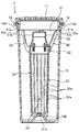
- FIG. 1 is a front view showing an example of the appearance of a portable simple water purifier made of a synthetic resin molded body according to this embodiment
- FIG. 2 is a cross-sectional view thereof.
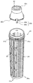
- FIG. 3 is an exploded perspective view of the water purifier as viewed obliquely from above
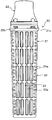
- FIG. 4 is a front view of a water purification cartridge formed of an outermost molded body housed and fixed in the water purifier
- FIG. 5 is a view of the water purification cartridge. It is a disassembled perspective view which shows an external appearance.
- FIG. 6 is a perspective view of a cartridge holder fitted into the water purifier.
- the portable simple water purifier 1 includes a cup-shaped container body 10 having a water storage section, and first to n-th plurality of water purification cartridges 20a to 20a. 20n, a cartridge holder 30 that holds the upper end portion of the first water purification cartridge 20a from above, and a lid body 11 that is detachably fitted to the upper end opening portion (drinking mouth) of the container body 10 by a bayonet mechanism. is doing.
- the second to nth water purification cartridges 20b to 20n are housed and fixed inside the first water purification cartridge 20a.
- the first water purification cartridge 20a will be simply referred to as the water purification cartridge 20 in the following with reference to FIGS.
- a seal ring 12 is interposed between the lid 11 and the upper end opening of the container body 10 to maintain water tightness.
- the said container main body 10 is comprised, for example from AS resin, and protrusion 10a 'protrudes along the internal peripheral surface of the upper end opening (drinking mouth). At the center of the bottom surface of the container body 10, a mountain-shaped protrusion 10 b bulges upward along with the lower surface.
- AS resin is used as the material of the lid 11.
- the material of the cartridge holder 30 is MBS resin.
- the material of each member in the present invention is not particularly limited to the illustrated example as long as it is a thermoplastic resin.
- the lid 11 is fitted into the upper end opening of the container body 10 from the inside by a bayonet mechanism, but may be fixed by screwing.
- the four protrusions 10 a ′ are formed in the upper end opening of the container body 10 as described above.
- a key-shaped groove 11a for fitting the four protrusions 10a ' is formed on the outer peripheral surface of the fitting portion of the lid body 11.
- the water purification cartridge 20 includes a cartridge main body 21 made of a bottomed hollow cylinder and a cartridge lid 22 attached to the upper end opening of the cartridge main body 21.
- the cartridge main body 21 has a vertical lattice portion 23 and a horizontal lattice portion 24 adjacent to each other along the circumferential surface thereof and arranged with a phase difference of 180 °.
- the vertical lattice portion 23 has a plurality of rows of first openings (water passage holes) 23a in a vertical rectangular shape.
- the horizontal lattice portion 24 has a plurality of second openings (water passage holes) 24a having a horizontal rectangular shape. These openings are usually set to such a size that the internal water treatment agent cannot pass through.
- the surface of the first water purification cartridge 20a which will be described later, is encapsulated with a net made of monofilaments having openings smaller than the particle size of the water treatment agent. May be.
- a ring-shaped flange portion 21a is projected from the upper end opening of the cartridge body 21 along the outer peripheral surface thereof (see FIG. 5).
- the upper surface of the ring-shaped flange portion 21a is a horizontal surface for holding the cartridge holder 30 from below.
- a concave portion 21b for fitting the tip of the mountain-shaped protrusion 10b bulged to the bottom of the container main body 10 is formed at the bottom bottom center of the cartridge main body 21. That is, the bottom of the cartridge main body 21 has a shape recessed toward the inside of the cartridge main body 21.
- Four engaging holes 21c having a phase difference of 90 ° are formed on the peripheral edge of the cartridge body 21 above the ring-shaped flange portion 21a.
- An engagement claw 22b, which will be described later, of the cartridge lid 22 is engaged with the engagement hole 21c, so that the cartridge body 21 and the cartridge lid 22 are integrated.
- the cartridge lid 22 has a shape in which a cylindrical portion is connected to a small diameter end of a hollow conical cylinder.
- the lower end opening of the cartridge lid 22 has the same shape and the same size as the upper opening of the cartridge body 21.
- Four engaging claws 22b are provided in a projecting manner along the peripheral edge of the lower end opening at four locations corresponding to the formation sites of the four engaging holes 21c formed in the cartridge body 21.
- the engaging claw 22b includes a vertical piece 22b 'extending vertically downward from the inner surface of the peripheral edge of the lower end opening of the cartridge lid 22, and a claw piece bent from the lower end of the vertical piece 22b' and projecting radially. 22b ".
- each vertical piece 22 b ′ is elastically deformed, and the claw pieces 22 b ′′ of the respective engagement claws 22 b are engaged with the corresponding engagement holes 21 c, And the cartridge lid 22 are integrally engaged.
- the cartridge main body 21 and the cartridge lid 22 are engaged, granular activated carbon or ion exchange resin as a water treatment agent is accommodated in the cartridge main body 21.
- the opening (water passage hole) formed in the cartridge main body 21 is larger than the particle size of the water treatment agent, the granular same type or different type of water treatment agent has a shape retaining property and is suitable.
- Each type is stored in a plurality of bags (not shown) made of a net having openings, and is stored in the cartridge body 21. Examples of the bag include a net formed of a monofilament of a synthetic resin, and the like may be used as long as the granular water treatment agent does not leak and has water permeability.
- the one or more bag bodies at this time also serve as the water purification cartridge 20 in the present invention.
- the volume of the bag body and the filling amount of the water treatment agent to be stored are determined in consideration of the volume of the cartridge body 21 and the filling rate of the bag body.
- the cartridge lid 22 has a top plate, and a plurality (eight in the illustrated example) of water passage holes 22c are formed through the top plate.
- This water passage hole 22c also has the first and second openings (water passage holes) 23a, 24a of the vertical lattice portion 23 and the horizontal lattice portion 24 formed in the cartridge main body 21, and the water contained in the container main body. It becomes a water flow opening.
- the water flow holes 22c, 23a, 24a complicate the direction of water flow, and water comes into contact with the water treatment agent from multiple directions, leading to an improvement in purification efficiency.
- the water passage hole 22c formed in the top plate of the cartridge lid 22 can be eliminated.
- a water passage hole can also be formed in the peripheral wall portion.
- the cartridge holder 30 is provided with a first ring 31 and a second ring 32 at a desired interval in the vertical direction, and there are five between the first and second rings 31 and 32.
- the connection rod 33 is connected.
- the connection by the connection rod 33 may be linear, but the connection positions of the connection rods 33 are shifted with a slight phase difference between the first and second rings 31 and 32 to connect the connection rods 33. .
- the connecting rods 33 are attached so as to be twisted between the first and second rings 31 and 32.
- the outer diameter of the first ring 31 is substantially equal to the inner diameter of the upper end opening of the container main body 10, and the ring-shaped protrusion 10 a protrudes along the inner peripheral surface of the upper end opening of the container main body 10 on the outer peripheral surface thereof.
- the ring-shaped protrusion 10a is a holding portion of the cartridge holder 30 in the present invention, and the ring strips 31a and 31b are cartridge holding portions in the present invention.
- the outer diameter of the second ring 32 is equal to the outer diameter of the upper end opening of the water purification cartridge main body 21, and the lower end of the second ring 32 protrudes along the outer peripheral surface of the upper end opening of the cartridge main body 21. Is closely mounted on the upper surface of the flange portion 21a.
- the cartridge lid 22 side of the water purification cartridge 20 is inserted into the first ring 31 via the second ring 32 of the cartridge holder 30, and the cartridge holder 30. Is supported from below by the water purification cartridge 20.
- the water purification cartridge 20 and the cartridge holder 30 are inserted together through the opening of the container body 10.
- the mountain-shaped protrusion 10 b formed on the bottom of the container main body 10 is formed in the recess 21 b formed on the bottom of the water purification cartridge 20. The upper end of the is fitted.
- the water purification cartridge 20 is positioned and fixed inside the container body 10 of the portable water purifier 1 in a form sandwiched between the cartridge holder 30 and the protrusion 10b formed on the bottom of the container body 10. Is done.
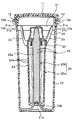
- FIG. 7 shows a first mode having typical first and second water purification cartridges of the present invention.
- a water purification cartridge composed of a synthetic resin container having a large number of first and second openings 23a, 24a which are long in length and breadth constitutes the first water purification cartridge 20a.
- the first water purification cartridge 20a accommodates and fixes a second water purification cartridge 20b made of a synthetic resin-made hollow container having a plurality of third openings 25 having round holes.
- the inner area of the first water purification cartridge 20a excluding the second water purification cartridge 20b disposed inside the first water purification cartridge 20a is the first water treatment unit.
- region of the 2nd water purification cartridge 20b becomes a 2nd water treatment part.
- the opening diameter of the third opening 25 is small and the distance between the adjacent third openings 25 is set longer than the size of the first and second openings 23a, 24a, and the number of openings and The opening area is made smaller than that of the first water purification cartridge 20a.
- granular activated carbon as a water treatment agent is stored, and in the internal region of the second water purification cartridge 20b, a granular as a water treatment agent is stored.
- the ion exchange resin is accommodated, and the water quality is changed to soft water at the same time as eliminating the odor of chalk.
- activated carbon is accommodated in the first water purification cartridge 20a and the second water purification cartridge 20b.
- An ion exchange resin is accommodated in The amount to be stored depends on the filling rate (hereinafter simply referred to as the filling rate) for each appropriate water purification cartridge 20a, 20b.
- the water treatment is performed on the first water purification cartridge 20a.
- the agent is stored therein, and the second water purification cartridge 20b is stored in the water purification cartridge 20 in a state where the agent is stored in a mesh-like bag body that has water permeability but prevents passage of the granular water treatment agent.
- the first water purification cartridge 20a is also housed in the water purification cartridge 20 in a state of being housed in the mesh bag.
- the filling rate of the water treatment agent into the water purification cartridge 20 greatly affects the water purification efficiency. Therefore, what is important in the present invention is that the volume of the plurality of water purification cartridges 20a to 20n, the size of the bag, and the filling rate of the water treatment agent stored in the bag are set to appropriate values. There is to do.
- the filling rate is relatively determined by the volumes of the water purification cartridges 20a to 20n and the volumes of the bags.
- the characteristic configuration for the present invention is that one or more water purification cartridges 20a to 20n are accommodated and fixed in the container body 10 of the portable simple water purifier 1, as described above.
- the purpose of purification differs depending on the water quality, it is ideal to adjust the type and amount of water treatment agent according to the type and amount of water treatment agent for each purpose. is there.
- a container having a water passage hole made of a synthetic resin having a bottom and a canopy is used.
- typical water treatment agents used in the present invention are activated carbon or ion exchange resin, L-ascorbic acid and L-ascorbate, which are used in appropriate combination.
- other water treatment agents may be used.
- granular or fibrous water treatment agents are used for the shape of these water treatment agents.
- the fibrous water treatment agent is preferably used in the form of a tape obtained by, for example, forming a non-woven sheet and then cutting it into an appropriate size because of its poor handleability and poor separation from water.
- FIGS. 8 to 10 schematically show examples of the synthetic resin having the bottom and the canopy as the two first and third water purification cartridges 20a and 20c.
- these examples are merely examples, and are not limited to these modifications.
- the first to third water purification cartridges 20a to 20c use fiber hollow containers, and the fibrous activated carbon is used as the water treatment agent stored in the second water purification cartridge 20b.
- Granular L-ascorbate is used as the water treatment agent stored in the cartridge 20a.
- the fibrous activated carbon used in this modification is itself a very short and thin fibrous form, and cannot be used as it is. Therefore, in this modification, a nonwoven fabric sheet is formed on a fibrous activated carbon using a synthetic resin binder, and this is cut into a predetermined width and length to form an elongated sheet.
- the amount of the binder is used less than the amount of binder used in ordinary nonwoven fabrics.
- the second water purification cartridge 20b a nonwoven fabric having a predetermined water permeability is used as the second water purification cartridge 20b, although it can capture single fibers of fibrous activated carbon.
- the upper and lower ends of the activated carbon formed in the shape of a long and narrow sheet are housed and fixed to a second water purification cartridge 20b made of nonwoven fabric having a required basis weight with an adhesive or the like.
- network which has an appropriate opening which does not let a granular water treatment agent pass is used for the 1st water purification cartridge 20a.
- FIG. 9 and 10 show examples of arrangement of two or more (three in the illustrated example) first to third water purification cartridges 20a to 20c.
- first to third water purification cartridges 20a to 20c hollow molded bodies in which the water holes made of synthetic resin having a bottom portion and a canopy are formed can be used.
- the modification shown in FIG. 9 is an example in which the first to third water purification cartridges 20a to 20c are vertically arranged in series
- FIG. 10 is an example in which the first to third water purification cartridges 20a to 20c are randomly arranged. is there.
- each of the water purification cartridges 20a to 20c may be entirely joined to each other, or a part thereof may be cut off. Further, the water purification cartridges 20a to 20c may be detachable from each other.
- each of the water purification cartridges 20a to 20c is prepared independently, and an appropriate amount of the same or different water treatment agent is stored in each according to the water quality. Then, the water purification cartridges 20a to 20c are laminated and pasted together. Furthermore, it is also possible to form the first to third water purification cartridges 20a to 20c by partitioning the inside of the first water purification cartridge 20a with water partitioning pieces. At this time, for example, the size of the water passage hole is changed, or each water purification cartridge is covered with a sheet-like material such as a nonwoven fabric having a different mesh. Accordingly, the water flow rate of each of the water purification cartridges 20a to 20c can be changed to adjust the water flow rate.
- FIG. 11 is an external perspective view showing an example of the second embodiment of the portable simple water purifier of the present invention.
- the main difference from the first embodiment is that a purified water outlet 11b is directly opened in the top plate portion of the lid 11 of the water purifier 1, and the purified water outlet 11b is also formed in the top plate portion.
- a tab 11c with a stopper for opening and closing and a water purification cartridge (not shown) is detachably attached to the lid 11 instead of the container body 10.
- the water purification cartridge may be provided on the lid by a known method.
- the water purification cartridge may be fitted inside the lid, or the water purification cartridge and the lid may be screwed together.
- the water purification cartridge is provided on the lid, but it can also be detachably provided in the opening of the container body 10 as in the first embodiment.
- FIG. 12 schematically shows a first aspect of the water purification cartridge 20 used in the second embodiment.
- the water purification cartridge 20 has the 1st water purification cartridge 20a and the 2nd water purification cartridge 20b.
- the 1st water purification cartridge 20a consists of a container with many opening made from a synthetic resin. Inside the container, ion exchange fibers are stored as a water treatment agent.
- the 2nd water purification cartridge 20b consists of a container with many small holes made from a synthetic resin. Inside the second water purification cartridge 20b, fibrous activated carbon is stored as a water treatment agent.
- the water treatment agent of the first water purification cartridge 20a is preferably covered with a sheet-like material such as a nonwoven fabric so that the water treatment agent does not flow into the water storage container of the water purifier 1.
- the upper end of the water purification cartridge 20 is detachably attached to the lid body 11, and the inside communicates with the water purification outlet 11b.
- a through hole 20a 'communicating with the second water purification cartridge 20b is formed in a part of the water treatment agent of the first water purification cartridge 20a.
- this through-hole 20a ′ two types of water, that is, water treated by both the first water purification cartridge 20a and the second water purification cartridge 20b and water treated only by the second water purification cartridge 20b, are provided. Water is discharged from the purified water outlet 11b. That is, the amount of water that passes through the water treatment unit varies depending on each water treatment unit.
- FIG. 13 schematically shows a modification of the water purification cartridge used in the second embodiment.
- the disc-shaped first water purification cartridge 20a overlaps on a concentric shaft.
- the outer diameters of the first water purification cartridge 20a and the second water purification cartridge 20b are formed to be equal.
- the water purification cartridge 20 is adapted to fit inside a lid (not shown).
- the first water purification cartridge 20a has a through hole 20a 'communicating with the second water purification cartridge 20b.
- the upper portion of the water purification cartridge 20 communicates with a water purification outlet (not shown).
- Fibrous activated carbon is used as a water treatment agent stored in the second water purification cartridge 20b.
- an ion exchange fiber is used as a water treatment agent accommodated in the first water purification cartridge 20a.
- the water treatment agent of the first water purification cartridge 20a and the second water purification cartridge 20b is preferably covered with a sheet-like material such as a porous nonwoven fabric so that the water treatment agent does not flow out into the water storage container.
- the water treated by the second water purification cartridge 20b and the first water purification cartridge 20a and the second water purification cartridge 20b are treated.
- the water that has passed through the through hole 20a ′ of the first water purification cartridge 20a is mixed.
- the water stored in the container body 10 by sucking water from the purified water discharge port 11b in a state where the container body 10 is left without shaking is a water treatment agent.
- the container main body 10 may be made of a soft material, and water may be pushed out to the purified water outlet by grasping the main body container, or the purified water outlet may be made into a straw shape to facilitate sucking. .
Landscapes
- Life Sciences & Earth Sciences (AREA)
- Hydrology & Water Resources (AREA)
- Engineering & Computer Science (AREA)
- Environmental & Geological Engineering (AREA)
- Water Supply & Treatment (AREA)
- Chemical & Material Sciences (AREA)
- Organic Chemistry (AREA)
- Water Treatment By Sorption (AREA)
- Treatment Of Water By Ion Exchange (AREA)
Abstract
カップ状の容器本体(10)と2以上の浄水カートリッジ(20a~20n)とを有する携帯用簡易型浄水器(1) である。浄水カートリッジ(20)内には粒状及び/又は繊維状の活性炭やイオン交換樹脂などからなる水処理剤が収納されている。各浄水カートリッジ(20a~20n)には、水質の違いに基づき同種又は異種の水処理剤が収納量を調整して収納される。各浄水カートリッジ(20a~20n)の通水能も調整可能とする。浄水器(1) が、このような簡単な浄化機構を備えることにより、安価に入手でき、特にオフィスや書斎、勉強部屋などに置かれたコップや茶碗の代わりに使用でき、短時間で確実に脱臭及び殺菌が効率的に且つ適切になされる。
Description
本発明は、カップ状容器の本体内部で、水道水や井戸水などの原水が短時間で飲用水としての水質基準を満足する水に浄化処理され、その浄化水を容器本体から直接飲むことができる携帯用の簡易型浄水器と同浄水器に適用される浄水カートリッジに関する。
一般的な携帯用の簡易型浄水器には、大別して2種類の浄水方式が知られている。一つ目は、原水を浄水器の貯水容器に集め、この原水をポンプ手段を介して加圧し、容器内に収容されている活性炭やゼオライトなどの浄化剤に接触させて塩素や臭気を吸着させて、異臭を取り除く。さらに、この原水を中空糸膜を通して微細な菌類や微生物を濾過して浄化するものである。二つ目は浄水器の貯水容器の内部に活性炭などの浄化剤を収納した和紙や不織布などからなる袋体、或いは金網からなる水透過性容器を直接浸漬し、重力を利用して袋体や水透過性容器の内外に出入りする原水を浄化剤に接触させて浄化するものである。提案されている携帯用の簡易型浄水器の大半は、これらの方式を採用している。
一つ目の浄水方式の具体例として、例えば特開平6-335671号公報(特許文献1)、特開平10-137740号公報(特許文献2)、特開2000-301139号公報(特許文献3)、特開2003-311263号公報(特許文献4)などが挙げられ、二つ目の浄水方式の具体例としては、例えば特開昭62-149395号公報(特許文献5)、特開昭62-227489号公報(特許文献6)、特許第3495993号公報(特許文献7)などを挙げることができる。
特許文献1によれば、貯水容器である有底の中空円柱状容器本体が各種合成樹脂からなる薄肉の軟質材料で作られ、この容器本体の口部開口に接続・離脱可能な浄水部を接続する。原水が満たされた容器本体を指で搾圧して、原水を浄水部の水流出開口に向けて押し出す。この押し出しの途中にて原水が中空糸膜及び活性炭に接触しながら流れて、濾過と吸着の浄化処理がなされ、浄水が作り出される。特許文献4により提案されている浄水器も特許文献1と浄水方式は同じであるが、活性炭と中空糸膜とを流れる原水の流れの順序が逆になっている。
また、特許文献2によれば、容器本体が蛇腹状に形成され、その伸縮性を生かしてハンドルを手で操作することにより容器本体を伸縮させ、取水バルブとドレンバルブとを必要に応じて切り換え、原水を取水源から取水し、或いは浄水をドレンさせる。
一方、特許文献3によれば、上側容器と下側容器とがネジ嵌合により分離可能とされ、上側容器の上部にはポンプレバーを突出させている。また、上側容器のポンプ部に水封状態で連通する浄水吐出ノズルを有している。下側容器には原水導入口が形成され、同下側容器の内部に浄水カートリッジが格納されている。前記原水導入口には原水導入用ホースが挿通され、同ホースの一端を前記カートリッジの原水導入口に連結して、同ホースの他端を原水中に没してポンプレバーを操作する。原水を前記ホースを介して浄水カートリッジ内へと導入し、原水を浄化したのち、前記浄水吐出ノズルから吐出させる。
上記特許文献5では、活性炭やイオン交換樹脂などの浄水能を有する物質を、例えば和紙や不織布からなる透水性の膜状物で包んだ浄水パックを水に浸漬して水の浄化を行っている。なお、同特許文献5には、前記パックの使用に際して、やかんなどの容器内の原水に浸漬した前記パックを揺り動かし、又は容器内の水道水を攪拌することにより、塩素の吸着能率を上げる旨が記載されている。
特許文献6もまた、浄水能を有する物質を不織布からなる袋体に収納して、これを原水に浸漬して水を浄化する。このときの浄水能を有する物質に活性炭とL-アスコルビン酸及び/又はL-アスコルビン酸塩とを含む浄水剤が使われる。また、同文献6では、前記浄水能を有する物質が入った不織布からなる袋を単に水中に浸漬するだけでは浮き上がってしまい、浄化効率が低くなるため、前記袋体を球状の金属製網体からなる沈降具に収容して、これを原水に入れて沈降させ、原水を浄化している。
上記特許文献7の浄活水器は、ペットボトルと同様の形状をもつボトル型容器本体と、ボトル型容器に収納と取出しができる全体に透水開孔を有するカプセルとから構成される。同カプセルは、金属板を使って両端に天蓋部と底部とを有する有孔円筒状に成形されている。前記金属板の合わせ目を割れ目として残して、外から力が加わらない自然状態では、前記カプセルはボトル型容器本体の呑口開口を通過できない大きさに形成されている。前記カプセルは、その弾性に抗して内側へ押圧することにより前記割れ目の幅を縮小させて前記呑口開口を通過させる。このカプセルには、原水の浄化と活性化とがなされる浄活水剤が収納された前記カプセルをボトル型容器内の原水中に浸漬して浄活水化する。ボトル型容器内のカプセルは呑口よりも大きいため、呑口から抜け出ることがなく、ボトル型容器内に確実に保持される。
ここで、特許文献1~4により提案されている携帯用簡易型浄水器は、いずれもポンプ機能を利用しているため、必然的に浄水器の構造が複雑になる傾向にあり、部品点数も必然的に多く、その組み付け及び分解作業に煩雑なものが多い。そのため、生産コストの増加につながりやすく、製品価格への影響も大きい。その点、特許文献5~7によって提案された携帯用簡易型浄水器は、構造が簡単であるがため、部品点数も少なく材料費や製作費も比較的低く抑えることができる。これらの課題に加えて、例えば特許文献1の携帯用簡易型浄水器では、その構成から全ての構成部品が使い捨ての対象となっており、資源の再利用を考えたとき更なる改良が望まれる。
ところで、一般に浄水時間を短縮するには浄水剤と原水との接触を多くすることが有効であることが知られている。例えば、上記特許文献5によれば、原水中の残留塩素の吸着効率を上げるため、原水に浸漬した浄水用パックを直接揺り動かすか、或いは原水を攪拌することが良いとしている。しかるに、この特許文献5のような携帯用簡易型浄水器にあって、浄水用パックを揺り動かしたり、原水を攪拌しようとすると、容器の蓋を取り外して外から攪拌具を原水中に挿入し、攪拌具を操作する必要があり、周辺に原水が飛び散る虞れが多い。一方、例えば特許文献7のボトル型携帯用浄活水器は、その容器本体が呑口の小さなペットボトル型であるため、蓋付き容器内部の原水中に入れられた浄活水用カプセルを攪拌具を用いて揺り動かすこと、或いは原水を攪拌すること自体が難しい。さらに、いざカプセルを容器本体から取り出そうとするとき、容器内でカプセルを外部から変形させることも難しく、浄水器自体と一緒に廃棄する全くの使い捨て用に作られている。
一方、前記特許文献7にも記載されていると同様に、特に市街地のオフィスや書斎、勉強部屋などにあって、清浄化された飲用水を飲みたいとき、近くのお店まで出掛けて飲用水などのボトルや缶を買い求めることが面倒なため、最近は屋内に引かれた水道水を直接飲用水として飲用するケースが増えてきている。しかして、このようにオフィスや自宅などで一気に飲む水の量は、精々コップや茶碗一杯ぐらいであって、それ以上の量を一気に飲みきれないし、残った水は次に飲むときまで、机などの上に置いておくことが多い。しかも飲みたいと思うと、直ぐにでも飲みたくなるのが常である。
近年の浄化技術の発展は著しく、水道水を飲用に供しても健康上には特に影響を及ぼすことは少なくなった。しかし、大型の浄化設備で大量に処理された多くの浄水、特に水道水には塩素消毒が施されており、更には塩素消毒が施された浄水には発癌性をもつと言われるトリハロメタンの発生の懸念がある。また水源となる湖沼や河川の富栄養化の下で繁殖する藻類等の微生物の代謝によるかび臭さや、残留塩素から発せられるカルキ臭さなども飲用には適さない。
そのため、上記特許文献6のように、活性炭とL-アスコルビン酸及び/又はL-アスコルビン酸塩との2種類の水処理剤を透水性を有する不織布などの水処理剤収納体に収納し、これを被処理水中に浸漬して、水処理機能の異なる、例えば遊離塩素を吸着・分解する機能と、カビ臭、トリハロメタン等を吸着する機能とを同時発揮して、美味な飲料水を簡便に製造し得る水処理具が提案されている。しかるに、この特許文献6にて提案されている水処理具は、既述したように浮き上がりを避けるため、わざわざ水処理剤収納体を単一の金属製球状網体からなる沈降具に収容しなければならないという課題がある。加えて、水質が異なっていても異質の水処理剤の配合割合は一定となりやすく、異なる水質の水との間で浄水機能のバランスを失いかねない。
本発明は、上述の事情に鑑みてなされたものであり、その具体的な目的は、特にオフィスや書斎、勉強部屋などに置かれたコップや茶碗の代わりに使用でき、短時間で浄化できる簡単で且つ異なる水質の水であっても浄水機能のバランスがとれた浄化機能をもつコップ型の携帯用簡易型浄水器を安価に提供することにある。
本発明者等は、上記目的を達成すべく様々な検討を重ねた。コップ程度の大きさをもつ携帯用簡易型浄水器にあって、浄化速度と浄化効率を高めるには、浄水器の内部に収容する浄水剤自体の表面積をできるだけ大きくし、その表面に水道水を素早く効率的に接触させる必要がある。浄水剤自体は、安価でなくてはならない。かかる要求を満たす水処理剤としては、活性炭やイオン交換樹脂、或いはL-アスコルビン酸、L-アスコルビン酸塩がある。これらの材料を、様々な大きさの粒状又は繊維状に形成すると、取り扱いやすさと水との接触面積も任意に調整できるので好ましい。
ただし、水中に水処理剤を浸漬するだけでは、そのままで水を飲むことはできない。静置された容器本体に入っている水の場合は、水の流動がないため容器本体内の水全体を浄水剤に接触させることが難しい。これを効率的に接触させるには、上記特許文献5に記載されているように、浄水用パックを浄水中で積極的に揺らすか、水を攪拌させて、パック内外への水の流動を促すことが望ましい。
本発明の携帯用簡易型浄水器は、上述のように、その形状と大きさとを家庭や職場などで身近に使うコップや茶碗程度の形状及び大きさを有することを前提としたとき、浄水器を手に持って容器ごと揺らす(振とうする)ことができることから、水と水処理剤とを効率的に接触させることができる。ただし、浄水器の容器本体自体が小さいために手に持って振りやすいが、容器本体中の水が飲み口から外にこぼれやすくもなる。これを防ぐには、浄水器の飲み口に取り外し可能でシール性の高い蓋を取り付ける必要がある。ここで振とうとは浄水器を手に持って揺らす動作を言う。
ところで、上述のとおり、脱臭能力や脱臭機構の異なる同種又は異種の複数種類の水処理剤を使ってバランス良く機能させようとしても、水質の異なる水に対しては、複数種類の水処理剤の配合率と配合量とが一律では脱臭能が期待通りに発揮されない。つまり、各水処理剤の配合率と配合量とが水質及び水量に適合していないときは、そのうちの幾つかの水処理剤が多過ぎたり少な過ぎたりして無駄が生じ、或いは所望の脱臭能力が発揮できないことになりやすい。
そこで、更なる検討を重ねた結果、同質又は異質の前記水処理剤を使うとき、それらの水処理剤ごとに独立させて水の処理に当たらせると同時に、水との接触量を調整できるようにすることが必要であるとの結論を得た。この結論を得て到達したのが、以下に述べる本発明である。
本発明にあって最も基本的な構成は、貯水部を有する容器本体と、蓋体と、1以上の浄水カートリッジと、前記浄水カートリッジを固定保持するカートリッジホルダーとを備え、前記容器本体を振とうして前記容器本体内を流動する水を浄化する携帯用簡易型浄水器であって、前記浄水カートリッジが少なくとも2以上の水処理部を有し、前記水処理部はそれぞれ処理能力や処理機構の異なる水処理剤を有し、処理水が前記水処理剤に接触するまでの圧力損失が異なることを特徴としている。
言い換えると、貯水部を有する容器本体と、蓋体と、浄水カートリッジと、を備えた携帯用簡易型浄水器であって、前記浄水カートリッジが2つ以上の水処理部を有し、前記水処理部はそれぞれ処理能力の異なる水処理剤を有し、被処理水が、前記水処理部を通水する際の通水量が、前記水処理部によって異なることを特徴としている。
このような構成とすることで、複数の水処理部のうち、水の処理速度が速い水処理剤を有する水処理部では相対的に通水量を少なくし、処理速度が遅い水処理剤を有する水処理部では相対的に通水量を多くすることができる。そのため、それぞれの水処理剤の処理能力や処理機構が異なったとしても通水量を調整することで、所望の水処理が可能となり、水処理剤の交換時期を合わせることができる。また、水処理剤の種類によっては、全ての水を処理する必要がなく、一定量の水を処理するだけでよい物がある。そのような水処理剤を用いる場合にも、通水量を調整することができるので、それぞれの水処理剤をバランス良く機能させることができる。
また、本発明の携帯用簡易型浄水器にあって、基本的な一つの構成として、前記容器本体を振とうして前記容器本体内を流動する水を浄化することを特徴としている。
このような構成とすることで、各水処理部内で被処理水と水処理剤とを効率的に且つ均等に接触させることができ、充分な浄水性能を得ることができる。
このような構成とすることで、各水処理部内で被処理水と水処理剤とを効率的に且つ均等に接触させることができ、充分な浄水性能を得ることができる。
また、本発明に係る携帯用簡易型浄水器では、前記水処理部は、少なくとも第一水処理部と第二水処理部とを有し、前記第一水処理部と前記第二水処理部は、それぞれ容器に収容され、各容器は通水孔を有し、前記通水孔はそれぞれの水処理部ごとに開口面積を異ならせることができる。
このような構成とすることで、浄水器を振とうさせて浄水を得る際に、第一水処理部と第二水処理部とに流入する水の量が異なるようになる。従って、それぞれの水処理部での通水量を調節することができ、それぞれの水処理剤をバランス良く機能させることができる。
このような構成とすることで、浄水器を振とうさせて浄水を得る際に、第一水処理部と第二水処理部とに流入する水の量が異なるようになる。従って、それぞれの水処理部での通水量を調節することができ、それぞれの水処理剤をバランス良く機能させることができる。
また、本発明に係る携帯用簡易型浄水器では、前記容器が多数の開口を有する合成樹脂製の成形容器、或いは多孔性のシート状物からなることが好ましい。
このような構成とすることで、振とうして浄水を得る際に、開口の大きさや孔の大きさが異なる成形容器又はシート状物にそれぞれの水処理部が収容されるため、第一水処理部と第二水処理部との圧力損失を変えることができる。従って、簡易でありながら効率よく通水量を調節することができる。
このような構成とすることで、振とうして浄水を得る際に、開口の大きさや孔の大きさが異なる成形容器又はシート状物にそれぞれの水処理部が収容されるため、第一水処理部と第二水処理部との圧力損失を変えることができる。従って、簡易でありながら効率よく通水量を調節することができる。
また、本発明の構成は、携帯容器本体と浄水カートリッジとを有する携帯用簡易型浄水器であって、前記浄水カートリッジが、第一水処理部と同第一水処理部の内部にある第二水処理部とを備えることを特徴とすることができる。
言い換えると、前記水処理部は、第一水処理部と第二水処理部を有し、前記第一水処理部と前記第二水処理部とはそれぞれ容器に収容され、前記第一水処理部の内部に前記第二水処理部を備えていることを特徴としている。
このような構成とすることで、第一処理部を通過する水の一部が第二処理部を通過することになる。そのため、この第二処理部を通過する水は圧力損失が大きくなる。従って、第二処理部を通水する水の量は、第一処理部より少なくなり、簡易でありながら効率よく通水量を調節することができる。
言い換えると、前記水処理部は、第一水処理部と第二水処理部を有し、前記第一水処理部と前記第二水処理部とはそれぞれ容器に収容され、前記第一水処理部の内部に前記第二水処理部を備えていることを特徴としている。
このような構成とすることで、第一処理部を通過する水の一部が第二処理部を通過することになる。そのため、この第二処理部を通過する水は圧力損失が大きくなる。従って、第二処理部を通水する水の量は、第一処理部より少なくなり、簡易でありながら効率よく通水量を調節することができる。
また、本発明に係る携帯用簡易型浄水器では、前記浄水カートリッジが、前記容器本体の内部に交換可能に収容固定されていることが好ましい。
このような構成とすることで、浄水器を振とうして浄化する際に、浄水カートリッジだけが動くことなく、容器本体と一体となって振とうさせることができる。従って、浄水カートリッジの水処理部に水を充分に行き渡らせることができ、充分な浄水能力を得ることができる。また、容器本体内部に浄水カートリッジが収容固定されているため、浄水カートリッジだけを撹拌する必要がなく、周辺に水が飛び散る可能性を低くすることができる。
このような構成とすることで、浄水器を振とうして浄化する際に、浄水カートリッジだけが動くことなく、容器本体と一体となって振とうさせることができる。従って、浄水カートリッジの水処理部に水を充分に行き渡らせることができ、充分な浄水能力を得ることができる。また、容器本体内部に浄水カートリッジが収容固定されているため、浄水カートリッジだけを撹拌する必要がなく、周辺に水が飛び散る可能性を低くすることができる。
また、本発明に係る携帯用簡易型浄水器では、前記容器本体は底部に内方に向かう突出部を有し、前記浄水カートリッジは底部に内方に向かう凹陥部を有し、前記突出部と前記凹陥部との嵌合時、前記容器本体の底部が前記浄水カートリッジを下方から位置決め支持されてなることが好ましい。
このような構成とすることで、浄水器に浄水カートリッジを差し込む際に、突出部と凹陥部が嵌合するため、浄水カートリッジの底部をしっかりと支持することができる。従って、浄水器を振とうして浄化する際に、浄水カートリッジも一体となって振とうさせることができる。そのため、浄水カートリッジの水処理部に水を充分に行き渡らせることができ、充分な浄水能力を得ることができる。
また、本発明に係る携帯用簡易型浄水器では、前記浄水カートリッジを固定保持するカートリッジホルダーを備え、前記容器本体が、前記カートリッジホルダーを保持するホルダー保持部を有し、前記カートリッジホルダーが前記浄水カートリッジを下方から挿入保持するカートリッジ保持部を有していることが好ましい。
このような構成とすることで、浄水カートリッジの上方をしっかりと支持することができる。従って、浄水器を振とうして浄化する際でも、容器本体に固定保持されるため浄水カートリッジだけが動くことを防ぐことができ、容器本体と一体となって振とうすることができる。そのため、水処理部に水を充分に行き渡らせることができ、充分な浄水能力を得ることができる。
このような構成とすることで、浄水カートリッジの上方をしっかりと支持することができる。従って、浄水器を振とうして浄化する際でも、容器本体に固定保持されるため浄水カートリッジだけが動くことを防ぐことができ、容器本体と一体となって振とうすることができる。そのため、水処理部に水を充分に行き渡らせることができ、充分な浄水能力を得ることができる。
また、本発明の携帯用簡易型浄水器にあって、もう一つの好適な基本的な構成として、前記蓋体は、浄水吐水口を有し、前記浄水カートリッジは、前記容器本体の上端開口部に着脱可能に接続固定され、前記水処理部は、第一水処理部と第二水処理部とを有し、前記第一水処理部又は前記第二水処理部のいずれか一方は、もう一方の水処理部に連通する貫通孔を有し、前記浄水カートリッジの上端と前記浄水吐水口とが連通していることが望ましい。
このような構成とすることで、浄水カートリッジを通水することで水が処理され、浄水吐水口から吐水されるが、貫通孔によって、一方の水処理部を通過せずに吐水口から吐水される。そのため、通水量を調整することができる。
このような構成とすることで、浄水カートリッジを通水することで水が処理され、浄水吐水口から吐水されるが、貫通孔によって、一方の水処理部を通過せずに吐水口から吐水される。そのため、通水量を調整することができる。
また、本発明に係る浄水カートリッジであって、基本的な構造は、貯水部を有する容器本体と、その蓋体とを備えた携帯用簡易型浄水器に用いる浄水カートリッジであって、前記浄水カートリッジが、2つ以上の水処理部を有し、前記水処理部はそれぞれ水処理剤を有し、被処理水が前記水処理部を通水する際の通水量が前記水処理部によって異なることを特徴としている。
また、本発明に係る浄水カートリッジでは、前記水処理部は、第一水処理部(第一浄水カートリッジ)と、第二水処理部(第二浄水カートリッジ)とを有し、前記第一水処理部と、前記第二水処理部はそれぞれ容器に収容され、該容器は通水孔を有し、前記通水孔はそれぞれの水処理部で大きさが異なることが好ましい。
また、本発明に係る浄水カートリッジでは、前記水処理部は、第一水処理部と、第二水処理部を有し、前記第一水処理部と、前記第二水処理部はそれぞれ容器に収容され、前記第一水処理部の内部に前記第二水処理部を備えていることが好ましい。
また、本発明に係る浄水カートリッジでは、前記水処理部は、第一水処理部と第二水処理部を有し、前記第一水処理部又は前記第二水処理部のいずれか一方は、もう一方の水処理部に連通する貫通孔を有していることが好ましい。
このような構成にすることで、複数の水処理部の内、水の処理速度が速い水処理剤を有する水処理部は通水量を少なくし、処理速度が遅い水処理剤を有する水処理部は通水量を多くすることができる。そのため、それぞれの水処理剤の処理能力が異なったとしても通水量を調整することで、水処理剤の交換時期を合わせることができる。また、水処理剤の種類によっては、全ての水を処理する必要がなく、一定量の水を処理するだけで良い場合がある。そのような水処理剤を用いる際は、通水量を調整することができるので、それぞれの水処理剤をバランス良く機能させることができる。
上記浄水カートリッジは、前記水処理部が、互いに着脱可能であると良い。更に、上記浄水カートリッジは、前記水処理剤が、粒状又は繊維状の活性炭、イオン交換樹脂、L-アスコルビン酸及びL-アスコルビン酸塩のうちの少なくとも1つを使うことが好ましい。
また、前記浄水カートリッジは、前記第一水処理部と前記第二水処理部とが、異なる水処理剤を備えることが好ましい。
また、前記浄水カートリッジは、前記第一水処理部と前記第二水処理部とが、異なる水処理剤を備えることが好ましい。
上記携帯用簡易型浄水器にあって、上記浄水カートリッジを少なくとも2以上の一体又は分離可能な浄水カートリッジで構成し、各浄水カートリッジには、それぞれ異質又は同質の水処理剤を収容する。そのため、その各浄水カートリッジに異質の脱臭・殺菌力が効果的に発揮される上に、既述したとおり、各水処理剤がもつ所望の脱臭機能を有効に働かせることができる。ここで同質の水処理剤とは、例えば同じ活性炭であっても、その吸着能力に差のある2種類の活性炭を用い、これら2種類の活性炭の量を調整した上でそれらを2以上の浄水カートリッジにそれぞれ収納して用いる場合を言う。2以上の浄水カートリッジは、それぞれ浄水器本体に分離可能に固着されている。
更に、前記浄水カートリッジは、携帯用簡易型浄水器を振とうすると、浄水器に収容固定されている浄水カートリッジも同時に振とうされる。その際に、各浄水カートリッジの内外を通水孔を介して、水が各浄水カートリッジ内を万遍なく流動して、各浄水カートリッジの内部に収納された水処理剤に効率的に接触し、各水処理剤による所要の脱臭・殺菌が確実に且つ適正になされる。ここで実験によれば、人が上記浄水器を手に持って、1回/秒の速度で振とうを続けたとき、1分間続けることが限度であることが分かっている。それ以上振とうを続けることもできなくはないが可能なかぎり60秒以下に抑えることが望ましい。
本発明にあっては、前記浄水カートリッジを浄水器の容器本体に交換可能に固定することが肝要である。
上述のように、複数の浄水カートリッジを固定した浄水器を所要時間振とうすると、浄水器本体に入っている水が万遍なく浄水カートリッジの内外を流動し、全体が均等に浄化される。このとき本発明にあっては、水質に合わせて複数の浄水カートリッジに収納される同質又は異質の水処理剤の種類を選定する。更に、その収納量を予めバランス良く調整しておけば、効率的且つ適切に各水処理剤の脱臭・殺菌力が発揮され、水処理剤の無駄を低減させることができる。
また、各浄水カートリッジが独立しているときは、予め各浄水カートリッジの通水量を調整しておくことができる。例えば、各浄水カートリッジに形成される通水孔の孔径を異なるようにしておけばよい。また2以上の浄水カートリッジが仕切り材を構成部材の一部とする場合には、各仕切り材及び浄水カートリッジ本体に形成される通水孔の孔径を調整して形成することにより、それらの通水量を変更させることができる。そのためには、予め孔径の異なる複数種類の浄水カートリッジを用意しておくと良い。
なお、2以上の浄水カートリッジの配置の形態としては、水処理剤を収納した1の浄水カートリッジの内部に、同じく同質又は異質の水処理剤を収納した他の浄水カートリッジを収容して、二重に配置したり、或いは2以上の浄水カートリッジを直列的に又は並列的に、更にはそれらを組み合わせて一体化して配置することができる。この場合には、浄水カートリッジ同士の重なった部分の通水量の調整は、通水孔の重なり具合を調整したり、或いは通水孔の孔径を調整すれば、各浄水カートリッジ間の通水量を調整することができる。
以下、本発明を好適な実施の形態に基づいて、図面を参照しながら具体的に説明する。なお、本発明は以下に述べる実施形態に限るものではなく、特許請求の範囲を越えない範囲内において多様な変更が可能である。
以下に述べる実施形態は、粒状及び繊維状の水処理剤を使用する例を中心に説明する。
以下に述べる実施形態は、粒状及び繊維状の水処理剤を使用する例を中心に説明する。
(第1実施形態)
まず本発明の代表的な第1実施形態である携帯用簡易型浄水器の構造について具体的に説明する。
図1は本実施形態に係る合成樹脂製の成形体からなる携帯用簡易型浄水器の外観の一例を示す正面図、図2は同断面図である。図3は前記浄水器を斜め上方から見た分解斜視図、図4は前記浄水器に収納固定される最も外側に配される成形体からなる浄水カートリッジの正面図、図5は同浄水カートリッジの外観を示す分解斜視図である。図6は前記浄水器の内部に嵌め込まれるカートリッジホルダーの斜視図である。
まず本発明の代表的な第1実施形態である携帯用簡易型浄水器の構造について具体的に説明する。
図1は本実施形態に係る合成樹脂製の成形体からなる携帯用簡易型浄水器の外観の一例を示す正面図、図2は同断面図である。図3は前記浄水器を斜め上方から見た分解斜視図、図4は前記浄水器に収納固定される最も外側に配される成形体からなる浄水カートリッジの正面図、図5は同浄水カートリッジの外観を示す分解斜視図である。図6は前記浄水器の内部に嵌め込まれるカートリッジホルダーの斜視図である。
図示実施形態に係る携帯用簡易型浄水器1は、貯水部を有するカップ状の容器本体10と、同容器本体10に取り外し可能に収納固定される第1~第nの複数の浄水カートリッジ20a~20nと、第1浄水カートリッジ20aの上端部を上から保持するカートリッジホルダー30と、容器本体10の上端開口部(飲み口)に取り外し可能にバヨネット機構によって内嵌着される蓋体11とを有している。また、図示を省略しているが、第2~第n浄水カートリッジ20b~20nは、前記第1浄水カートリッジ20aの内部に収納固定されている。この第1浄水カートリッジ20aの理解しやすくするため、以下、図1~図6の図示に従い、第1浄水カートリッジ20aを単に浄水カートリッジ20として述べることにする。
前記蓋体11と前記容器本体10の上端開口部との間にはシールリング12が介装され水密性が保持される。上記容器本体10は、例えばAS樹脂から構成され、その上端開口(飲み口)の内周面に沿って突起10a’が突出している。容器本体10の底面中央には下面とともに山形状の突出部10bが上方に向けて膨出している。上記蓋体11の材質は、例えばABS樹脂が使われている。因みに、この実施形態では、カートリッジホルダー30の材質はMBS樹脂が使われている。ただし、本発明における各部材の材質は、熱可塑性樹脂であれば特に図示例に限定されない。
本実施形態にあっては、前記蓋体11は、前記容器本体10の上端開口部に内側からバヨネット機構によって嵌着されているが、螺合により固定してもよい。図示例によれば、容器本体10の上端開口部には、上述のように4個の突起10a’が形成されている。また、前記蓋体11における嵌着部外周面には、4個の前記突起10a’をそれぞれ嵌着するためのカギ形状をした溝11aが形成されている。この蓋体11が容器本体10の上端開口部に嵌着されると、蓋体11の下端は上記カートリッジホルダー30の、後述する第1リング31の上面に密接する。
図1~図6において、浄水カートリッジ20は、有底中空筒体からなるカートリッジ本体21と、同カートリッジ本体21の上端開口に取り付けられるカートリッジ蓋22とを備えている。前記カートリッジ本体21は、その周面に沿って縦格子部23と横格子部24とが互いに隣り合って180°の位相差をもって配されている。縦格子部23は縦長方形の複数列の第1開口(通水孔)23aを有している。横格子部24は横長方形の複数段の第2開口(通水孔)24aを有している。これらの開口は、通常、内部の水処理剤が通過できない大きさに設定される。もし、開口が内部の水処理剤の粒径よりも大きい場合には、後述する第1浄水カートリッジ20aの表面を水処理剤の粒径より小さい開口をもつモノフィラメントから作成された網体で被包してもよい。
また、カートリッジ本体21の上端開口部には、その外周面に沿ってリング状のフランジ部21aが突設されている(図5参照)。このリング状のフランジ部21aの上面は、上記カートリッジホルダー30を下から保持するために水平面とされている。またカートリッジ本体21の底部下面中央には、上記容器本体10の底部に膨出された山形状の突出部10bの先端を嵌め込むための凹陥部21bが形成されている。すなわち、カートリッジ本体21の底部は、カートリッジ本体21の内部に向けて陥没した形状となっている。カートリッジ本体21の前記リング状のフランジ部21a上方の周縁部には、90°の位相差をもって4個の係着孔21cが形成されている。この係着孔21cに上記カートリッジ蓋22の後述する係着爪22bが係着して、カートリッジ本体21とカートリッジ蓋22とを一体化する。
前記カートリッジ蓋22は、図4及び図5に示すように、中空円錐胴の小径端に円筒部を接続した形状を有している。このカートリッジ蓋22の下端開口は前記カートリッジ本体21の上部開口と同一形状、同一寸法を有している。その下端開口周縁に沿って、カートリッジ本体21に形成された4個の上記係着孔21cの形成部位に対応する4ヵ所に都合4個の上記係着爪22bが突設されている。この係着爪22bは、前記カートリッジ蓋22の下端開口部の周縁部内面から垂直下方に延出する垂直片22b’と、同垂直片22b’の下端から屈曲して放射方向に突出する爪片22b”とから構成されている。前記カートリッジ本体21の上部開口を前記カートリッジ蓋22により閉塞するには、各係着爪22bに対応する係着孔21cを対向させて、カートリッジ蓋22の下端開口をカートリッジ本体21の上部開口に突き合わせ状態で押し下げると、各垂直片22b’が弾性変形して、各係着爪22bの爪片22b”が対応する係着孔21cに係着し、カートリッジ本体21とカートリッジ蓋22とが係着一体化される。
こうしてカートリッジ本体21とカートリッジ蓋22とが係着される前に、カートリッジ本体21の内部に水処理剤となる粒状の活性炭やイオン交換樹脂を収容する。本発明にあっては、カートリッジ本体21に形成される開口(通水孔)が水処理剤の粒度よりも大きいときは、粒状の同種又は異種の水処理剤を保形性を有し適当な開口をもつ網物からなる複数の袋体(図示省略)に種類ごとに収納し、これをカートリッジ本体21に収容する。袋体としては、例えば合成樹脂のモノフィラメントで形成された網体などが挙げられるが、粒状の水処理剤が漏れず、通水性のあるものであれば良い。このときの1以上の袋体も、本発明における浄水カートリッジ20となる。袋体の容積と収納する水処理剤の充填量は、カートリッジ本体21の容積を勘案して、しかも袋体に対する充填率をも考慮して決められる。
また本実施形態にあっては、前記カートリッジ蓋22が天板を有し、その天板に複数個(図示例では8個)の通水孔22cが貫通して形成されている。この通水孔22cもまた、カートリッジ本体21に形成される縦格子部23及び横格子部24の第1及び第2開口(通水孔)23a,24aとともに、容器本体内に入っている水の通水開口となる。この通水孔22c、23a、24aによって、水の流動の方向が複雑化し、水処理剤に対して多方向から水が接触するようになり、浄化効率の向上につながる。なお本発明にあって、カートリッジ蓋22の天板に形成される前記通水孔22cは排除することもできる。或いはカートリッジ蓋22が閉じたときに内部の水と接する周壁部分を有する場合には、その周壁部分にも通水孔を形成することもできる。
上記カートリッジホルダー30は、図6に示すように、上下に所望の間隔をおいて第1リング31及び第2リング32とが配され、その第1及び第2リング31,32の間を5本の連結杆33で連結している。この連結杆33による連結は直線的でもよいが、第1及び第2リング31,32の間で各連結杆33の連結位置を僅かな位相差をもってずらせて、各連結杆33を連結している。換言すると、第1及び第2リング31,32の間で各連結杆33を捩じるようにして取り付けている。このようにして連結することによって、第1及び第2リング31,32の間隔に多少の変動が生じても、これを受け入れることを可能にする。
第1リング31の外径は、上記容器本体10の上端開口部の内径にほぼ等しく、その外周面には容器本体10の上端開口部の内周面に沿って突出する上記リング状の突起10aを上下から挟着する2本のリング条31a,31bを有している。前記リング状の突起10aが、本発明における前記カートリッジホルダー30の保持部であり、また前記リング条31a,31bが、本発明におけるカートリッジ保持部となる。一方、上記第2リング32の外径は上記浄水カートリッジ本体21における上端開口部の外径に等しく、第2リング32の下端はカートリッジ本体21の上端開口部の外周面に沿って突出するリング状のフランジ部21aの上面に密接載置される。
いま、浄水カートリッジ20を容器本体10に固定保持させるには、まず浄水カートリッジ20のカートリッジ蓋22の側を、カートリッジホルダー30の第2リング32を介して第1リング31に差し込んで、カートリッジホルダー30を浄水カートリッジ20にて下から支持させる。次いで、この状態にて浄水カートリッジ20とカートリッジホルダー30とを一緒に容器本体10の開口から差し入れる。このとき、浄水カートリッジ20の底部中央を容器本体10の底部中央に向けて差し込むと、浄水カートリッジ20の底部に形成された凹陥部21bに容器本体10の底部に形成された山形状の突出部10bの上端部が嵌合する。
ここで、蓋体11をもって容器本体10を閉塞すると、上述のとおり、蓋体11の下端が第1リング31の上面に密接しており、浄水カートリッジ20の底部凹陥部21bは携帯用簡易型浄水器1の容器本体10の底部から上方に膨出する突出部10bによって下からしっかりと支持された状態となる。こうして、浄水カートリッジ20は、カートリッジホルダー30と、容器本体10の底部に形成された突出部10bとによって上下を挟まれた形で、携帯用簡易型浄水器1の容器本体10の内部に位置決め固定される。
図7は、本発明の代表的な第1及び第2浄水カートリッジをもつ第1の態様を示している。第1の態様では、多数の縦横に長い第1及び第2開口23a,24aをもつ合成樹脂製の容器からなる浄水カートリッジが、第1浄水カートリッジ20aを構成する。この第1浄水カートリッジ20a内に、多数の丸孔の第3開口25をもつ合成樹脂製の成形中空容器からなる第2浄水カートリッジ20bを収容固定している。この第1の様態にあって、第1浄水カートリッジ20aの内部に配される第2浄水カートリッジ20bを除いた第1浄水カートリッジ20aの内部領域が第1水処理部となる。また、第2浄水カートリッジ20bの内部領域が第2水処理部となる。この例では、前記第1及び第2開口23a,24aの大きさに比して、第3開口25の開口径が小さく且つ隣接する第3開口25間の距離が長く設定されて、開口数及び開口面積を第1浄水カートリッジ20aのそれよりも小さくしている。第1浄水カートリッジ20aと第2浄水カートリッジ20bとの間の内部領域に、例えば水処理剤としての粒状の活性炭を収納するとともに、第2浄水カートリッジ20bの内部領域には、水処理剤としての粒状のイオン交換樹脂を収容して、カルキ臭を排除すると同時に水質を軟水となるよう変えている。
このとき、原水が水道水と井戸水では水質が異なるため、例えば原水が水道水であるときは遊離残留塩素の量が多いことから、活性炭を第1浄水カートリッジ20aに収容し、第2浄水カートリッジ20bにイオン交換樹脂を収容する。それらの収納する量は適正な各浄水カートリッジ20a,20bに対する充填率(以下、単に充填率と言う。)に従う。
本発明にあっては、図7に示すように、上記第1浄水カートリッジ20aに形成された通水孔22cの開口が粒状の水処理剤より小さい場合は、同第1浄水カートリッジ20aに水処理剤を収納し、その中に第2浄水カートリッジ20bを、通水性を有するが粒状の水処理剤の通過を阻止するメッシュ状の袋体に収納した状態で、浄水カートリッジ20に収納する。なお、カートリッジ蓋22の通水孔22cの開口が粒状の水処理剤より大きい場合は、第1浄水カートリッジ20aもメッシュ状の袋体に収納した状態で、浄水カートリッジ20に収納する。ここで、様々な実験を積み重ねた結果、既述したとおり、粒状の水処理剤に効率的に水を接触させるには、浄水器全体を手にて揺らす(振とうする)ことが肝要であり、このとき浄水カートリッジ20に対する水処理剤の充填率が浄水効率に大きく影響することが判明している。そのため、本発明にあって重要なことは、複数の浄水カートリッジ20a~20nの容積、袋体の大きさ、及び袋体の内部に収納される水処理剤の充填率を如何に適切な値とするかにある。前記充填率は浄水カートリッジ20a~20nの各容積及び各袋体の容積によって相対的に決まる。
本発明にとって特徴的な構成は、既述したとおり、1以上の浄水カートリッジ20a~20nを携帯用簡易型浄水器1の容器本体10に収容固定することにある。しかし、その実施にあたっては、水質の違いによって浄化目的が異なる場合には、その目的ごとに、水処理剤の種類や処理量に応じて水処理剤の種類や量を調整するのが理想的である。本発明における浄水カートリッジ20には、底部及び天蓋を有する合成樹脂製の前記通水孔が形成された容器が用いられる。
なお、本発明に用いられる代表的な水処理剤は、活性炭又はイオン交換樹脂、L-アスコルビン酸及びL-アスコルビン酸塩であり、それらを適宜組み合わせて使用する。もちろん、他の水処理剤を使ってもよい。また、これらの水処理剤の形状は、粒状又は繊維状の水処理剤が使われる。ここで繊維状の水処理剤は、その取扱い性の悪さ及び水との分離性の悪さから、例えば不織布シートを成形したのち適当な大きさに切断して得られるテープ状で使用すると良い。
本発明では、図7に示した第1の態様以外にも、例えば図8~図10に示す変形例がある。それらの例を順次説明する。ここで、図8~図10に示す例は、二つの第1及び第3浄水カートリッジ20a,20cとして、底部及び天蓋を有する合成樹脂製の一例を模式的に示している。もちろん、これらの例は単なる例示であり、これらの変形例に限るものではない。
図8に示す変形例も、第1~第3浄水カートリッジ20a~20cにそれぞれ繊維製の中空容器を使い、第2浄水カートリッジ20bに収納する水処理剤として繊維状の活性炭を使い、第1浄水カートリッジ20aに収納する水処理剤には粒状のL-アスコルビン酸塩を使っている。この変形例に使われる繊維状の活性炭は、それ自体が極めて短く細い繊維状であって、繊維状のまま使うことは不可能である。そこで、本変形例では繊維状の活性炭に合成樹脂バインダーを使って不織布シートを成形し、これを所定の幅と長さに切断して細長いシート状に形成する。もちろん、バインダーの量は、通常の不織布に使われるバインダーの量よりも少なめに使われる。
しかして、携帯用簡易型浄水器1の振とう操作により容器本体10内に入っている水が激しく流動するため、細長いシート状の繊維状活性炭からは繊維状活性炭の単繊維が離脱しやすい。そこで、本変形例では第2浄水カートリッジ20bとして、繊維状活性炭の単繊維を捕捉できるが所定の通水性を有する不織布を使っている。前記細長いシート状に形成された活性炭の上下両端を、所要の目付からなる不織布製の第2浄水カートリッジ20bに接着剤などによって収納固定する。また本変形例では、第1浄水カートリッジ20aには粒状の水処理剤を通さない適当な開口を有する網が使われる。
図9及び図10は、2以上(図示例では3つ)の第1~第3浄水カートリッジ20a~20cの配置例を示している。これらの例では、第1~第3浄水カートリッジ20a~20cとして、底部及び天蓋を有する合成樹脂製の前記通水孔が形成された中空成形体を使うことができる。図9に示す変形例は、第1~第3浄水カートリッジ20a~20cを上下に直列的に配した例であり、図10は第1~第3浄水カートリッジ20a~20cをランダムに配した例である。これらの配置に当たり、各浄水カートリッジ20a~20cを互いに全面的に接合しても、或いは一部を切り離しても良い。また、浄水カートリッジ20a~20cを互いに着脱可能としても良い。
各第1~第3浄水カートリッジ20a~20cを互いに全面的に接合する場合、各浄水カートリッジ20a~20cを独立して作成し、それぞれに水質に応じて同質又は異質の水処理剤を適量収納し、各浄水カートリッジ20a~20cを重ね合わせて貼り付け一体化する。更には、第1浄水カートリッジ20aの内部を通水性仕切り片によって仕切り、各第1~第3浄水カートリッジ20a~20cを形成することも可能である。このとき、例えば、通水孔の大きさを変えたり、各浄水カートリッジをメッシュの異なる不織布などのシート状物で覆う。これによって、各浄水カートリッジ20a~20cの通水量を変更して、それぞれの通水性を調整することもできる。
(第2実施形態)
図11は本発明の携帯用簡易型浄水器の第2実施形態の一例を示す外観斜視図である。
この第2実施形態において上記第1実施形態と主に異なる点は、浄水器1の蓋体11の天板部に浄水吐水口11bが直接開口しており、同じく天板部に浄水吐水口11bを開閉する栓付きタブ11cが設けられている点と、図示せぬ浄水カートリッジが容器本体10ではなく蓋体11に着脱可能に取り付けられている点である。浄水カートリッジは公知の方法で蓋体に設けられれば良い。例えば浄水カートリッジを蓋部の内側に嵌め込むようにしても良く、浄水カートリッジと蓋体とが螺合するようにしても良い。なお、本実施形態では、浄水カートリッジを蓋体に設けるようにしているが、上記第1実施形態と同様に、容器本体10の開口部に着脱可能に設けることもできる。
図11は本発明の携帯用簡易型浄水器の第2実施形態の一例を示す外観斜視図である。
この第2実施形態において上記第1実施形態と主に異なる点は、浄水器1の蓋体11の天板部に浄水吐水口11bが直接開口しており、同じく天板部に浄水吐水口11bを開閉する栓付きタブ11cが設けられている点と、図示せぬ浄水カートリッジが容器本体10ではなく蓋体11に着脱可能に取り付けられている点である。浄水カートリッジは公知の方法で蓋体に設けられれば良い。例えば浄水カートリッジを蓋部の内側に嵌め込むようにしても良く、浄水カートリッジと蓋体とが螺合するようにしても良い。なお、本実施形態では、浄水カートリッジを蓋体に設けるようにしているが、上記第1実施形態と同様に、容器本体10の開口部に着脱可能に設けることもできる。
図12は、第2実施形態で用いる浄水カートリッジ20の第1の態様を模式的に示している。この浄水カートリッジ20の第1の態様によると、浄水カートリッジ20は第1浄水カートリッジ20aと第2浄水カートリッジ20bとを有している。第1浄水カートリッジ20aは合成樹脂製の多数の開口をもつ容器からなる。この容器の内部には、水処理剤としてイオン交換繊維が収納される。また、第2浄水カートリッジ20bも合成樹脂製の多数の小孔をもつ容器からなる。その第2浄水カートリッジ20bの内部には、水処理剤として繊維状の活性炭が収納される。第1浄水カートリッジ20aの水処理剤は、浄水器1の貯水容器に水処理剤が流出しないように、不織布などのシート状物で覆われていることが好ましい。浄水カートリッジ20の上端は蓋体11に着脱可能に取り付けられ、内部が浄水吐水口11bと連通している。
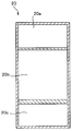
第1浄水カートリッジ20aの水処理剤の一部に第2浄水カートリッジ20bと連通する貫通孔20a’が形成されている。この貫通孔20a’が設けられていることにより、第1浄水カートリッジ20aと第2浄水カートリッジ20bとの双方にて処理される水と、第2浄水カートリッジ20bだけで処理される水との2種類の水が、浄水吐水口11bから排出される。すなわち、水処理部を通水する際の通水量が、各水処理部によって異なる。
しかして、容器本体10に貯水された水は、浄水吐水口11bから飲水する際には、第1浄水カートリッジ20a及び第2浄水カートリッジ20bの両水処理剤を通して処理された水と、第1浄水カートリッジ20aの貫通孔を通り、第2浄水カートリッジ20bの水処理剤だけで処理された水とが混合されることになる。この2種類の処理された水を飲水することによって、飲水に適した硬度の水を得ることができる。
図13は第2実施形態で用いる浄水カートリッジの変形例を模式的に表している。円板状の第2浄水カートリッジ20bの上に、円板状の第1浄水カートリッジ20aが同心軸上に重なっている。第1浄水カートリッジ20aと第2浄水カートリッジ20bの外径は等しく形成されている。この浄水カートリッジ20は、図示せぬ蓋体の内部に嵌合するようになっている。また、第1浄水カートリッジ20aは第2浄水カートリッジ20bと連通している貫通孔20a’を有している。浄水カートリッジ20の上方が図示せぬ浄水吐水口と連通している。第2浄水カートリッジ20bに収納される水処理剤として繊維状の活性炭が用いられる。また、第1浄水カートリッジ20aに収納される水処理剤としてイオン交換繊維を用いる。第1浄水カートリッジ20a及び第2浄水カートリッジ20bの水処理剤は、貯水容器に水処理剤が流出しないように、多孔性の不織布などのシート状物で覆うことが好ましい。また、第2浄水カートリッジ20bの下面には、水処理剤は通さず、水を通す下蓋体を設けるようにしても良い。
しかして、容器本体10に貯水された水は、浄水吐水口11bから飲水する際には、第2浄水カートリッジ20b及び第1浄水カートリッジ20aで処理された水と、第2浄水カートリッジ20bで処理されるだけで、第1浄水カートリッジ20aの貫通孔20a’を通過した水とが混合されていることになる。この2種類の処理された混合水を同時に飲水することによって、飲水に適した硬度の水を得ることができる。
なお、第2実施形態においては、振とうすることなく容器本体10を静置した状態で、浄水吐水口11bから水を吸引することによって容器本体10に貯水された水は万遍なく水処理剤を通って効率的に処理される。この吸引を効率的に行うため、容器本体10を軟質材量で作り、本体容器を握ることによって水を浄水吐水口へと押し出したり、或いは浄水吐水口をストロー形状にして吸いやすくしても良い。
1 携帯用簡易型浄水器
10 (カップ状の)容器本体
10a (リング状の)突起
10a’ 突起
10b (山形状の)突出部
11 蓋体
11a 溝
11b 浄水吐水口
11c 栓付きタブ
12 シールリング
20 浄水カートリッジ
20a~20c 第1~第3浄水カートリッジ
20a’ 貫通孔
21 カートリッジ本体(中空筒体)
21a リング状のフランジ部
21b 凹陥部
21c 係着孔
22 カートリッジ蓋
22b 係着爪
22b’ 垂直片
22b” 爪片
22c 通水孔
23 縦格子部
23a 第1開口(通水孔)
24 横格子部
24a 第2開口(通水孔)
25 第3開口(通水孔)
30 カートリッジホルダー
31 第1リング
31a,31b リング条
32 第2リング
33 連結杆
10 (カップ状の)容器本体
10a (リング状の)突起
10a’ 突起
10b (山形状の)突出部
11 蓋体
11a 溝
11b 浄水吐水口
11c 栓付きタブ
12 シールリング
20 浄水カートリッジ
20a~20c 第1~第3浄水カートリッジ
20a’ 貫通孔
21 カートリッジ本体(中空筒体)
21a リング状のフランジ部
21b 凹陥部
21c 係着孔
22 カートリッジ蓋
22b 係着爪
22b’ 垂直片
22b” 爪片
22c 通水孔
23 縦格子部
23a 第1開口(通水孔)
24 横格子部
24a 第2開口(通水孔)
25 第3開口(通水孔)
30 カートリッジホルダー
31 第1リング
31a,31b リング条
32 第2リング
33 連結杆
Claims (14)
- 貯水部を有する容器本体と、蓋体と、浄水カートリッジと、を備えた携帯用簡易型浄水器であって、
前記浄水カートリッジが2つ以上の水処理部を有し、前記水処理部はそれぞれ水処理剤を有し、被処理水が、前記水処理部を通水する際の通水量が、前記水処理部によって異なる携帯用簡易型浄水器。 - 前記容器本体を振とうして前記容器本体内を流動する水を浄化する請求項1に記載の携帯用簡易型浄水器。
- 前記水処理部は、第一水処理部と、第二水処理部を有し、前記第一水処理部と、前記第二水処理部はそれぞれ容器に収容され、各容器は通水孔を有し、前記通水孔はそれぞれの水処理部で大きさが異なる請求項2に記載の携帯用簡易型浄水器。
- 前記容器が合成樹脂製の多数の開口を有する成形容器からなる請求項3に記載の携帯用簡易型浄水器。
- 前記容器が多孔性のシート状物からなる請求項3に記載の携帯用簡易型浄水器。
- 前記水処理部は、第一水処理部と、第二水処理部を有し、前記第一水処理部と、前記第二水処理部はそれぞれ容器に収容され、前記第一水処理部の内部に前記第二水処理部を備えた、請求項2に記載の携帯用簡易型浄水器。
- 前記浄水カートリッジが、前記容器本体の内部に交換可能に収容固定されている請求項2~5いずれか1項に記載の携帯用簡易型浄水器。
- 前記容器本体は底部に突出部を有し、前記浄水カートリッジは底部に凹陥部を有し、前記突出部と前記凹陥部との嵌合時、前記容器本体の底部が前記浄水カートリッジを下方から位置決め支持してなる、請求項2~6のいずれか1項に記載の携帯用簡易型浄水器。
- 前記浄水カートリッジを固定保持するカートリッジホルダーを備え、前記容器本体が、前記カートリッジホルダーを保持するホルダー保持部を有し、前記カートリッジホルダーが前記浄水カートリッジを下方から挿入保持するカートリッジ保持部を有してなる、請求項7又は8に記載の携帯用簡易型浄水器。
- 前記蓋体は、浄水吐出口を有し、前記浄水カートリッジは、前記蓋体に着脱可能に接続され、前記水処理部は、第一水処理部と第二水処理部を有し、前記第一水処理部又は前記第二水処理部のいずれか一方は、もう一方の水処理部に連通する貫通孔を有している請求項1に記載の携帯用簡易型浄水器。
- 貯水部を有する容器本体と、その蓋体とを備えた携帯用簡易型浄水器に用いる浄水カートリッジであって、
前記浄水カートリッジが、2つ以上の水処理部を有し、前記水処理部はそれぞれ水処理剤を有し、被処理水が前記水処理部を通水する際の通水量が前記水処理部によって異なる浄水カートリッジ。 - 前記水処理部は、第一水処理部と、第二水処理部を有し、前記第一水処理部と、前記第二水処理部はそれぞれ容器に収容され、該容器は通水孔を有し、前記通水孔はそれぞれの水処理部で大きさが異なる請求項11に記載の浄水カートリッジ。
- 前記水処理部は、第一水処理部と、第二水処理部を有し、前記第一水処理部と、前記第二水処理部はそれぞれ容器に収容され、前記第一水処理部の内部に前記第二水処理部を備えた、請求項11に記載の浄水カートリッジ。
- 前記水処理部は、第一水処理部と第二水処理部を有し、前記第一水処理部又は前記第二水処理部のいずれか一方は、もう一方の水処理部に連通する貫通孔を有している請求項11に記載の浄水カートリッジ。
Priority Applications (2)
| Application Number | Priority Date | Filing Date | Title |
|---|---|---|---|
| JP2014537412A JP5910749B2 (ja) | 2013-08-01 | 2014-07-30 | 携帯用簡易型浄水器とその浄水カートリッジ |
| CN201480054425.9A CN105636909A (zh) | 2013-08-01 | 2014-07-30 | 携带用简易型净水器和其净水盒 |
Applications Claiming Priority (2)
| Application Number | Priority Date | Filing Date | Title |
|---|---|---|---|
| JP2013160755 | 2013-08-01 | ||
| JP2013-160755 | 2013-08-01 |
Publications (1)
| Publication Number | Publication Date |
|---|---|
| WO2015016245A1 true WO2015016245A1 (ja) | 2015-02-05 |
Family
ID=52431775
Family Applications (1)
| Application Number | Title | Priority Date | Filing Date |
|---|---|---|---|
| PCT/JP2014/070020 Ceased WO2015016245A1 (ja) | 2013-08-01 | 2014-07-30 | 携帯用簡易型浄水器とその浄水カートリッジ |
Country Status (3)
| Country | Link |
|---|---|
| JP (1) | JP5910749B2 (ja) |
| CN (1) | CN105636909A (ja) |
| WO (1) | WO2015016245A1 (ja) |
Cited By (2)
| Publication number | Priority date | Publication date | Assignee | Title |
|---|---|---|---|---|
| JP2015100120A (ja) * | 2015-01-13 | 2015-05-28 | 矢崎総業株式会社 | ハーネスのノイズフィルタ構造 |
| JP2020157287A (ja) * | 2019-03-26 | 2020-10-01 | 貢 坂東 | ポータブル水素水ボトル |
Families Citing this family (2)
| Publication number | Priority date | Publication date | Assignee | Title |
|---|---|---|---|---|
| CN109757944B (zh) * | 2018-12-30 | 2021-02-23 | 福建金源泉科技发展有限公司 | 一种便携式超滤摇摇净水杯 |
| KR102425414B1 (ko) * | 2020-01-30 | 2022-07-27 | 윤형건 | 정수 필터 및 이를 포함하는 물통 |
Citations (4)
| Publication number | Priority date | Publication date | Assignee | Title |
|---|---|---|---|---|
| JPS61115188U (ja) * | 1984-12-28 | 1986-07-21 | ||
| JPS6421793U (ja) * | 1987-07-29 | 1989-02-03 | ||
| JP3005774U (ja) * | 1994-06-29 | 1995-01-10 | 株式会社早川バルブ製作所 | 簡易ミネラルウオーター生成器 |
| JP3055577U (ja) * | 1998-07-06 | 1999-01-22 | 有限会社天美製作所 | 液体処理具 |
Family Cites Families (4)
| Publication number | Priority date | Publication date | Assignee | Title |
|---|---|---|---|---|
| JPS61115188A (ja) * | 1984-11-09 | 1986-06-02 | Toa Medical Electronics Co Ltd | 網状赤血球検査方法 |
| JPH0355577U (ja) * | 1989-10-02 | 1991-05-29 | ||
| JP2715371B2 (ja) * | 1995-12-28 | 1998-02-18 | クリタック株式会社 | 浄水装置 |
| EP1354857B1 (en) * | 2000-12-25 | 2008-02-20 | Mitsubishi Rayon Co., Ltd. | Pitcher type water purifier and purification cartridge for the water purifier |
-
2014
- 2014-07-30 JP JP2014537412A patent/JP5910749B2/ja not_active Expired - Fee Related
- 2014-07-30 WO PCT/JP2014/070020 patent/WO2015016245A1/ja not_active Ceased
- 2014-07-30 CN CN201480054425.9A patent/CN105636909A/zh active Pending
Patent Citations (4)
| Publication number | Priority date | Publication date | Assignee | Title |
|---|---|---|---|---|
| JPS61115188U (ja) * | 1984-12-28 | 1986-07-21 | ||
| JPS6421793U (ja) * | 1987-07-29 | 1989-02-03 | ||
| JP3005774U (ja) * | 1994-06-29 | 1995-01-10 | 株式会社早川バルブ製作所 | 簡易ミネラルウオーター生成器 |
| JP3055577U (ja) * | 1998-07-06 | 1999-01-22 | 有限会社天美製作所 | 液体処理具 |
Cited By (2)
| Publication number | Priority date | Publication date | Assignee | Title |
|---|---|---|---|---|
| JP2015100120A (ja) * | 2015-01-13 | 2015-05-28 | 矢崎総業株式会社 | ハーネスのノイズフィルタ構造 |
| JP2020157287A (ja) * | 2019-03-26 | 2020-10-01 | 貢 坂東 | ポータブル水素水ボトル |
Also Published As
| Publication number | Publication date |
|---|---|
| JPWO2015016245A1 (ja) | 2017-03-02 |
| CN105636909A (zh) | 2016-06-01 |
| JP5910749B2 (ja) | 2016-04-27 |
Similar Documents
| Publication | Publication Date | Title |
|---|---|---|
| US7507338B2 (en) | Universal water purifier unit assembly device | |
| US9550138B2 (en) | Gravity fluid/water filter system | |
| US7708958B2 (en) | System and containers for water filtration and item sanitization | |
| US5733448A (en) | Manually pressurized water filtering container | |
| TW536526B (en) | Pitcher type water purifier and purification cartridge for the water purifier | |
| US6238552B1 (en) | Universal insert for a water purifier | |
| US5536403A (en) | Liquid purification system with microfiltration means, disinfection means and adsorption means | |
| US20070102332A1 (en) | Multi-stage water purification device | |
| US20110303618A1 (en) | Reusable water filter systems and methods | |
| US9539526B2 (en) | Filter assembly and systems/methods of dispensing from and storing the filter assembly | |
| JP4863425B2 (ja) | 浄水カートリッジ及び浄水器 | |
| JP5910749B2 (ja) | 携帯用簡易型浄水器とその浄水カートリッジ | |
| CN104703924A (zh) | 净水盒和净水器 | |
| KR101181632B1 (ko) | 정수기의 정수탱크에 설치되는 살균 및 필터유닛 | |
| JP5927945B2 (ja) | 携帯用簡易型浄水器 | |
| JP2003164714A (ja) | 濾過装置 | |
| US20150197427A1 (en) | Water purifier | |
| KR101825089B1 (ko) | 휴대용 정수기 | |
| JPH10211954A (ja) | 水処理用カートリッジおよびこのカートリッジと飲料ボトルとの組合せ構造ならびにこのカートリッジを用いた水処理方法 | |
| JP2013158658A (ja) | 携帯用簡易型浄水器 | |
| RU2568730C1 (ru) | Индивидуальное средство для очистки жидкости | |
| JP2014188433A (ja) | 携帯用簡易浄水器 | |
| JP2010247137A (ja) | 浄水器及びその使用方法 | |
| US10556807B2 (en) | Device for treating water for household use | |
| JPH055994Y2 (ja) |
Legal Events
| Date | Code | Title | Description |
|---|---|---|---|
| ENP | Entry into the national phase |
Ref document number: 2014537412 Country of ref document: JP Kind code of ref document: A |
|
| 121 | Ep: the epo has been informed by wipo that ep was designated in this application |
Ref document number: 14831530 Country of ref document: EP Kind code of ref document: A1 |
|
| NENP | Non-entry into the national phase |
Ref country code: DE |
|
| 122 | Ep: pct application non-entry in european phase |
Ref document number: 14831530 Country of ref document: EP Kind code of ref document: A1 |