WO2015015847A1 - 電池容器用表面処理鋼板の製造方法 - Google Patents
電池容器用表面処理鋼板の製造方法 Download PDFInfo
- Publication number
- WO2015015847A1 WO2015015847A1 PCT/JP2014/061021 JP2014061021W WO2015015847A1 WO 2015015847 A1 WO2015015847 A1 WO 2015015847A1 JP 2014061021 W JP2014061021 W JP 2014061021W WO 2015015847 A1 WO2015015847 A1 WO 2015015847A1
- Authority
- WO
- WIPO (PCT)
- Prior art keywords
- iron
- battery
- steel sheet
- nickel
- nickel alloy
- Prior art date
- Legal status (The legal status is an assumption and is not a legal conclusion. Google has not performed a legal analysis and makes no representation as to the accuracy of the status listed.)
- Ceased
Links
Images




Classifications
-
- C—CHEMISTRY; METALLURGY
- C21—METALLURGY OF IRON
- C21D—MODIFYING THE PHYSICAL STRUCTURE OF FERROUS METALS; GENERAL DEVICES FOR HEAT TREATMENT OF FERROUS OR NON-FERROUS METALS OR ALLOYS; MAKING METAL MALLEABLE, e.g. BY DECARBURISATION OR TEMPERING
- C21D9/00—Heat treatment, e.g. annealing, hardening, quenching or tempering, adapted for particular articles; Furnaces therefor
- C21D9/46—Heat treatment, e.g. annealing, hardening, quenching or tempering, adapted for particular articles; Furnaces therefor for sheet metals
-
- B—PERFORMING OPERATIONS; TRANSPORTING
- B32—LAYERED PRODUCTS
- B32B—LAYERED PRODUCTS, i.e. PRODUCTS BUILT-UP OF STRATA OF FLAT OR NON-FLAT, e.g. CELLULAR OR HONEYCOMB, FORM
- B32B15/00—Layered products comprising a layer of metal
- B32B15/01—Layered products comprising a layer of metal all layers being exclusively metallic
- B32B15/011—Layered products comprising a layer of metal all layers being exclusively metallic all layers being formed of iron alloys or steels
-
- B—PERFORMING OPERATIONS; TRANSPORTING
- B32—LAYERED PRODUCTS
- B32B—LAYERED PRODUCTS, i.e. PRODUCTS BUILT-UP OF STRATA OF FLAT OR NON-FLAT, e.g. CELLULAR OR HONEYCOMB, FORM
- B32B15/00—Layered products comprising a layer of metal
- B32B15/01—Layered products comprising a layer of metal all layers being exclusively metallic
- B32B15/013—Layered products comprising a layer of metal all layers being exclusively metallic one layer being formed of an iron alloy or steel, another layer being formed of a metal other than iron or aluminium
- B32B15/015—Layered products comprising a layer of metal all layers being exclusively metallic one layer being formed of an iron alloy or steel, another layer being formed of a metal other than iron or aluminium the said other metal being copper or nickel or an alloy thereof
-
- C—CHEMISTRY; METALLURGY
- C21—METALLURGY OF IRON
- C21D—MODIFYING THE PHYSICAL STRUCTURE OF FERROUS METALS; GENERAL DEVICES FOR HEAT TREATMENT OF FERROUS OR NON-FERROUS METALS OR ALLOYS; MAKING METAL MALLEABLE, e.g. BY DECARBURISATION OR TEMPERING
- C21D1/00—General methods or devices for heat treatment, e.g. annealing, hardening, quenching or tempering
- C21D1/26—Methods of annealing
-
- C—CHEMISTRY; METALLURGY
- C21—METALLURGY OF IRON
- C21D—MODIFYING THE PHYSICAL STRUCTURE OF FERROUS METALS; GENERAL DEVICES FOR HEAT TREATMENT OF FERROUS OR NON-FERROUS METALS OR ALLOYS; MAKING METAL MALLEABLE, e.g. BY DECARBURISATION OR TEMPERING
- C21D6/00—Heat treatment of ferrous alloys
- C21D6/005—Heat treatment of ferrous alloys containing Mn
-
- C—CHEMISTRY; METALLURGY
- C21—METALLURGY OF IRON
- C21D—MODIFYING THE PHYSICAL STRUCTURE OF FERROUS METALS; GENERAL DEVICES FOR HEAT TREATMENT OF FERROUS OR NON-FERROUS METALS OR ALLOYS; MAKING METAL MALLEABLE, e.g. BY DECARBURISATION OR TEMPERING
- C21D6/00—Heat treatment of ferrous alloys
- C21D6/008—Heat treatment of ferrous alloys containing Si
-
- C—CHEMISTRY; METALLURGY
- C22—METALLURGY; FERROUS OR NON-FERROUS ALLOYS; TREATMENT OF ALLOYS OR NON-FERROUS METALS
- C22C—ALLOYS
- C22C38/00—Ferrous alloys, e.g. steel alloys
-
- C—CHEMISTRY; METALLURGY
- C22—METALLURGY; FERROUS OR NON-FERROUS ALLOYS; TREATMENT OF ALLOYS OR NON-FERROUS METALS
- C22C—ALLOYS
- C22C38/00—Ferrous alloys, e.g. steel alloys
- C22C38/002—Ferrous alloys, e.g. steel alloys containing In, Mg, or other elements not provided for in one single group C22C38/001 - C22C38/60
-
- C—CHEMISTRY; METALLURGY
- C22—METALLURGY; FERROUS OR NON-FERROUS ALLOYS; TREATMENT OF ALLOYS OR NON-FERROUS METALS
- C22C—ALLOYS
- C22C38/00—Ferrous alloys, e.g. steel alloys
- C22C38/02—Ferrous alloys, e.g. steel alloys containing silicon
-
- C—CHEMISTRY; METALLURGY
- C22—METALLURGY; FERROUS OR NON-FERROUS ALLOYS; TREATMENT OF ALLOYS OR NON-FERROUS METALS
- C22C—ALLOYS
- C22C38/00—Ferrous alloys, e.g. steel alloys
- C22C38/04—Ferrous alloys, e.g. steel alloys containing manganese
-
- C—CHEMISTRY; METALLURGY
- C22—METALLURGY; FERROUS OR NON-FERROUS ALLOYS; TREATMENT OF ALLOYS OR NON-FERROUS METALS
- C22C—ALLOYS
- C22C38/00—Ferrous alloys, e.g. steel alloys
- C22C38/06—Ferrous alloys, e.g. steel alloys containing aluminium
-
- C—CHEMISTRY; METALLURGY
- C22—METALLURGY; FERROUS OR NON-FERROUS ALLOYS; TREATMENT OF ALLOYS OR NON-FERROUS METALS
- C22F—CHANGING THE PHYSICAL STRUCTURE OF NON-FERROUS METALS AND NON-FERROUS ALLOYS
- C22F1/00—Changing the physical structure of non-ferrous metals or alloys by heat treatment or by hot or cold working
- C22F1/10—Changing the physical structure of non-ferrous metals or alloys by heat treatment or by hot or cold working of nickel or cobalt or alloys based thereon
-
- C—CHEMISTRY; METALLURGY
- C23—COATING METALLIC MATERIAL; COATING MATERIAL WITH METALLIC MATERIAL; CHEMICAL SURFACE TREATMENT; DIFFUSION TREATMENT OF METALLIC MATERIAL; COATING BY VACUUM EVAPORATION, BY SPUTTERING, BY ION IMPLANTATION OR BY CHEMICAL VAPOUR DEPOSITION, IN GENERAL; INHIBITING CORROSION OF METALLIC MATERIAL OR INCRUSTATION IN GENERAL
- C23C—COATING METALLIC MATERIAL; COATING MATERIAL WITH METALLIC MATERIAL; SURFACE TREATMENT OF METALLIC MATERIAL BY DIFFUSION INTO THE SURFACE, BY CHEMICAL CONVERSION OR SUBSTITUTION; COATING BY VACUUM EVAPORATION, BY SPUTTERING, BY ION IMPLANTATION OR BY CHEMICAL VAPOUR DEPOSITION, IN GENERAL
- C23C10/00—Solid state diffusion of only metal elements or silicon into metallic material surfaces
- C23C10/02—Pretreatment of the material to be coated
-
- C—CHEMISTRY; METALLURGY
- C23—COATING METALLIC MATERIAL; COATING MATERIAL WITH METALLIC MATERIAL; CHEMICAL SURFACE TREATMENT; DIFFUSION TREATMENT OF METALLIC MATERIAL; COATING BY VACUUM EVAPORATION, BY SPUTTERING, BY ION IMPLANTATION OR BY CHEMICAL VAPOUR DEPOSITION, IN GENERAL; INHIBITING CORROSION OF METALLIC MATERIAL OR INCRUSTATION IN GENERAL
- C23C—COATING METALLIC MATERIAL; COATING MATERIAL WITH METALLIC MATERIAL; SURFACE TREATMENT OF METALLIC MATERIAL BY DIFFUSION INTO THE SURFACE, BY CHEMICAL CONVERSION OR SUBSTITUTION; COATING BY VACUUM EVAPORATION, BY SPUTTERING, BY ION IMPLANTATION OR BY CHEMICAL VAPOUR DEPOSITION, IN GENERAL
- C23C10/00—Solid state diffusion of only metal elements or silicon into metallic material surfaces
- C23C10/28—Solid state diffusion of only metal elements or silicon into metallic material surfaces using solids, e.g. powders, pastes
-
- C—CHEMISTRY; METALLURGY
- C25—ELECTROLYTIC OR ELECTROPHORETIC PROCESSES; APPARATUS THEREFOR
- C25D—PROCESSES FOR THE ELECTROLYTIC OR ELECTROPHORETIC PRODUCTION OF COATINGS; ELECTROFORMING; APPARATUS THEREFOR
- C25D3/00—Electroplating: Baths therefor
- C25D3/02—Electroplating: Baths therefor from solutions
- C25D3/12—Electroplating: Baths therefor from solutions of nickel or cobalt
-
- C—CHEMISTRY; METALLURGY
- C25—ELECTROLYTIC OR ELECTROPHORETIC PROCESSES; APPARATUS THEREFOR
- C25D—PROCESSES FOR THE ELECTROLYTIC OR ELECTROPHORETIC PRODUCTION OF COATINGS; ELECTROFORMING; APPARATUS THEREFOR
- C25D3/00—Electroplating: Baths therefor
- C25D3/02—Electroplating: Baths therefor from solutions
- C25D3/56—Electroplating: Baths therefor from solutions of alloys
- C25D3/562—Electroplating: Baths therefor from solutions of alloys containing more than 50% by weight of iron or nickel or cobalt
-
- C—CHEMISTRY; METALLURGY
- C25—ELECTROLYTIC OR ELECTROPHORETIC PROCESSES; APPARATUS THEREFOR
- C25D—PROCESSES FOR THE ELECTROLYTIC OR ELECTROPHORETIC PRODUCTION OF COATINGS; ELECTROFORMING; APPARATUS THEREFOR
- C25D5/00—Electroplating characterised by the process; Pretreatment or after-treatment of workpieces
- C25D5/34—Pretreatment of metallic surfaces to be electroplated
- C25D5/36—Pretreatment of metallic surfaces to be electroplated of iron or steel
-
- C—CHEMISTRY; METALLURGY
- C25—ELECTROLYTIC OR ELECTROPHORETIC PROCESSES; APPARATUS THEREFOR
- C25D—PROCESSES FOR THE ELECTROLYTIC OR ELECTROPHORETIC PRODUCTION OF COATINGS; ELECTROFORMING; APPARATUS THEREFOR
- C25D5/00—Electroplating characterised by the process; Pretreatment or after-treatment of workpieces
- C25D5/48—After-treatment of electroplated surfaces
- C25D5/50—After-treatment of electroplated surfaces by heat-treatment
-
- H—ELECTRICITY
- H01—ELECTRIC ELEMENTS
- H01M—PROCESSES OR MEANS, e.g. BATTERIES, FOR THE DIRECT CONVERSION OF CHEMICAL ENERGY INTO ELECTRICAL ENERGY
- H01M50/00—Constructional details or processes of manufacture of the non-active parts of electrochemical cells other than fuel cells, e.g. hybrid cells
- H01M50/10—Primary casings; Jackets or wrappings
- H01M50/116—Primary casings; Jackets or wrappings characterised by the material
- H01M50/124—Primary casings; Jackets or wrappings characterised by the material having a layered structure
-
- H—ELECTRICITY
- H01—ELECTRIC ELEMENTS
- H01M—PROCESSES OR MEANS, e.g. BATTERIES, FOR THE DIRECT CONVERSION OF CHEMICAL ENERGY INTO ELECTRICAL ENERGY
- H01M50/00—Constructional details or processes of manufacture of the non-active parts of electrochemical cells other than fuel cells, e.g. hybrid cells
- H01M50/10—Primary casings; Jackets or wrappings
- H01M50/116—Primary casings; Jackets or wrappings characterised by the material
- H01M50/124—Primary casings; Jackets or wrappings characterised by the material having a layered structure
- H01M50/126—Primary casings; Jackets or wrappings characterised by the material having a layered structure comprising three or more layers
- H01M50/128—Primary casings; Jackets or wrappings characterised by the material having a layered structure comprising three or more layers with two or more layers of only inorganic material
-
- H—ELECTRICITY
- H01—ELECTRIC ELEMENTS
- H01M—PROCESSES OR MEANS, e.g. BATTERIES, FOR THE DIRECT CONVERSION OF CHEMICAL ENERGY INTO ELECTRICAL ENERGY
- H01M2220/00—Batteries for particular applications
- H01M2220/10—Batteries in stationary systems, e.g. emergency power source in plant
-
- H—ELECTRICITY
- H01—ELECTRIC ELEMENTS
- H01M—PROCESSES OR MEANS, e.g. BATTERIES, FOR THE DIRECT CONVERSION OF CHEMICAL ENERGY INTO ELECTRICAL ENERGY
- H01M2220/00—Batteries for particular applications
- H01M2220/30—Batteries in portable systems, e.g. mobile phone, laptop
-
- H—ELECTRICITY
- H01—ELECTRIC ELEMENTS
- H01M—PROCESSES OR MEANS, e.g. BATTERIES, FOR THE DIRECT CONVERSION OF CHEMICAL ENERGY INTO ELECTRICAL ENERGY
- H01M6/00—Primary cells; Manufacture thereof
- H01M6/04—Cells with aqueous electrolyte
-
- Y—GENERAL TAGGING OF NEW TECHNOLOGICAL DEVELOPMENTS; GENERAL TAGGING OF CROSS-SECTIONAL TECHNOLOGIES SPANNING OVER SEVERAL SECTIONS OF THE IPC; TECHNICAL SUBJECTS COVERED BY FORMER USPC CROSS-REFERENCE ART COLLECTIONS [XRACs] AND DIGESTS
- Y02—TECHNOLOGIES OR APPLICATIONS FOR MITIGATION OR ADAPTATION AGAINST CLIMATE CHANGE
- Y02E—REDUCTION OF GREENHOUSE GAS [GHG] EMISSIONS, RELATED TO ENERGY GENERATION, TRANSMISSION OR DISTRIBUTION
- Y02E60/00—Enabling technologies; Technologies with a potential or indirect contribution to GHG emissions mitigation
- Y02E60/10—Energy storage using batteries
Definitions
- the present invention relates to a method for producing a surface-treated steel sheet for battery containers.
- alkaline batteries that are primary batteries, nickel-hydrogen batteries that are secondary batteries, lithium ion batteries, and the like are frequently used as operating power sources.
- Such batteries are required to have longer life and higher performance in accordance with higher performance of the mounted devices, and battery containers filled with power generation elements composed of positive electrode active materials, negative electrode active materials, and the like are also used as batteries.
- power generation elements composed of positive electrode active materials, negative electrode active materials, and the like are also used as batteries.
- Patent Document 1 As such a battery container, for example, in Patent Document 1, after a nickel plating layer is formed on a steel plate, an iron-nickel alloy plating layer is formed and processed so that the iron-nickel alloy layer becomes the inner surface of the battery container.
- a molded battery container is disclosed.
- the object of the present invention is to suppress the elution of iron inside the battery when it is used as a battery container, thereby extending the life of the battery and improving battery characteristics such as discharge characteristics. It is providing the manufacturing method of the surface-treated steel plate for battery containers made.
- the present inventors formed an iron-nickel alloy plating layer and a nickel plating layer in this order on at least one surface of the steel sheet, and then formed the outermost layer by heat treatment.
- the inventors have found that the above object can be achieved by setting the content ratio of Fe atoms on the outermost surface to 12 to 55 atomic%, and have completed the present invention.
- the third step of forming an iron-nickel alloy layer having a content ratio of Fe atoms on the outermost surface of 12 to 55 atomic% on the outermost layer by thermal diffusion by performing heat treatment after forming the nickel plating layer A method for producing a surface-treated steel sheet for battery containers is provided.
- the iron-nickel alloy plating layer when the iron-nickel alloy plating layer is formed in the first step, it is preferable to form an iron-nickel alloy plating layer having a Fe atom content of 15 to 65 atomic%. . In the manufacturing method of the present invention, it is preferable to form a nickel plating layer having a thickness of 0.1 to 0.5 ⁇ m when the nickel plating layer is formed in the second step.
- the elution of iron inside the battery when used as a battery container, the elution of iron inside the battery can be suppressed, which can extend the life of the battery and improve battery characteristics such as discharge characteristics.
- the manufacturing method of the surface-treated steel plate for battery containers made can be provided.
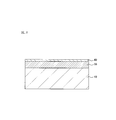
- FIG. 1 is a configuration diagram of a surface-treated steel sheet for battery containers according to the first embodiment.
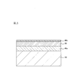
- FIG. 2 is a view for explaining a method of manufacturing the surface-treated steel sheet for battery containers according to the first embodiment.
- FIG. 3 is a diagram showing the results of measuring the Ni intensity and the Fe intensity with the high-frequency glow discharge optical emission spectrometer for the surface-treated steel sheet for battery containers according to the first embodiment.
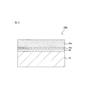
- FIG. 4 is a configuration diagram of the surface-treated steel sheet for battery containers according to the second embodiment.
- FIG. 5 is a view for explaining a method of manufacturing the surface-treated steel sheet for battery containers according to the second embodiment.
- FIG. 6 is a configuration diagram illustrating another example of the surface-treated steel sheet for battery containers according to the second embodiment.
- FIG. 7 is a diagram showing the results of measuring the Fe intensity and the Ni intensity with a high-frequency glow discharge emission spectroscopic analyzer for the surface-treated steel sheets for battery containers obtained in Examples and Comparative Examples.
- FIG. 1 is a diagram showing a configuration of a surface-treated steel sheet 100 for battery containers manufactured by the manufacturing method according to the present embodiment.
- nickel plating is performed, and then heat treatment such as continuous annealing or box annealing is performed, as shown in FIG.
- a surface-treated steel sheet for battery containers 100 in which an iron-nickel alloy layer 20 is formed on the steel sheet 10 is manufactured.
- the steel plate 10 that is the substrate of the surface-treated steel plate 100 for the battery container of the present embodiment is excellent in drawing workability, drawing ironing workability, and workability by drawing and bending back work (DTR).
- DTR drawing and bending back work
- low carbon aluminum killed steel carbon content 0.01 to 0.15% by weight
- ultra low carbon steel having a carbon content of 0.003% or less or ultra low carbon steel with Ti or Non-aging ultra-low carbon steel obtained by adding Nb or the like can be used.
- these steel hot-rolled plates are pickled to remove surface scale (oxide film), cold-rolled, and then subjected to electrolytic cleaning of rolling oil, or after the electrolytic cleaning What was annealed and temper-rolled is used as a substrate.
- the annealing may be either continuous annealing or box annealing, and is not particularly limited.
- the iron-nickel alloy layer 20 is a layer that is the outermost layer of the surface-treated steel sheet for battery containers 100. After iron-nickel alloy plating is performed on the steel sheet 10, nickel plating is performed. Thereafter, it is formed by further heat treatment such as continuous annealing or box annealing.
- an iron-nickel alloy plating layer 30 is formed on the steel plate 10 by performing iron-nickel alloy plating, and then the formed iron-nickel alloy plating layer 30 is formed.
- Surface treatment steel plate is obtained by forming nickel plating layer 40 by performing nickel plating on the top.
- heat treatment is performed on the surface-treated steel sheet shown in FIG. 2, and iron is diffused to the outermost surface by thermally diffusing each layer, thereby forming an iron-nickel alloy layer 20, and the surface for battery containers shown in FIG.
- a treated steel plate 100 is obtained.
- the iron-nickel alloy layer 20 formed in this way is such that the content ratio of Fe atoms on the outermost surface is controlled in the range of 12 to 55 atomic%.
- the present embodiment by controlling the content ratio of Fe atoms on the outermost surface of the formed iron-nickel alloy layer 20 to the above range, when the obtained surface-treated steel sheet for battery container 100 is used as a battery container, Due to the action of nickel present on the surface of the iron-nickel alloy layer 20, elution of iron into the electrolytic solution can be suppressed. Therefore, in this embodiment, when used as a battery container, by suppressing the elution of iron into the electrolyte, it is possible to prevent damage to the battery container due to the gas generated with the elution of iron, The battery life can be extended by improving the leakage resistance of the battery container.
- the hardness of the surface of the iron-nickel alloy layer 20 is made moderate by controlling the content ratio of Fe atoms on the outermost surface of the iron-nickel alloy layer 20 to the above range. Can do.
- processing such as drawing, ironing, DI or DTR forming is performed so that the iron-nickel alloy layer 20 becomes the inner surface of the battery container.
- fine and shallow cracks can be generated on the surface of the iron-nickel alloy layer 20.
- Such fine and shallow cracks can increase the contact area between the iron-nickel alloy layer 20 and the positive electrode mixture used in the battery, thereby reducing the internal resistance of the battery and reducing the discharge. Battery characteristics such as characteristics can be improved.
- the content ratio of Fe atoms on the outermost surface of the iron-nickel alloy layer 20 is too low, the hardness of the iron-nickel alloy layer 20 becomes too low, and the inner surface of the battery container is formed when being molded as a battery container. Since it cannot be cracked appropriately, the effect of reducing the internal resistance of the battery and improving the battery characteristics cannot be obtained sufficiently.
- the content ratio of Fe atoms on the outermost surface of the iron-nickel alloy layer 20 is too large, the content ratio of nickel on the outermost surface of the iron-nickel alloy layer 20 decreases, resulting in a decrease in corrosion resistance, and the resulting battery.
- iron is likely to elute into the electrolytic solution.
- the iron-nickel alloy layer 20 has a content ratio of Fe atoms on the outermost surface of 12 to 55 atomic%, preferably 12 to 53 atomic%, more preferably 15 to 50 atomic%. is there.
- the content ratio of Fe atoms on the outermost surface of the iron-nickel alloy layer 20 is controlled to the above range, as described above, when the obtained surface-treated steel sheet for battery container 100 is used as a battery container, the liquid leakage resistance In addition, battery characteristics can be improved.
- a method of measuring the content ratio of Fe atoms on the outermost surface of the iron-nickel alloy layer 20 for example, a method of measuring the surface of the iron-nickel alloy layer 20 with a scanning Auger electron spectrometer is used. Can do.
- the surface hardness of the iron-nickel alloy layer 20 is Vickers hardness (HV), preferably 210 to 250. If the Vickers hardness of the surface of the iron-nickel alloy layer 20 is too high, when the battery container is molded, the iron-nickel alloy layer 20 is deeply cracked, and the steel plate 10 is exposed, thereby the battery container. As a result, iron is eluted from the exposed portion of the steel plate 10 and the leakage resistance is reduced. On the other hand, if the Vickers hardness of the surface of the iron-nickel alloy layer 20 is too low, the inner surface of the battery container cannot be cracked properly when being molded as a battery container, so that the internal resistance of the battery is lowered and the battery characteristics are reduced. The effect of improving the quality cannot be obtained sufficiently.
- HV Vickers hardness
- the thickness of the iron-nickel alloy layer 20 is not particularly limited, but is preferably 0.6 to 3.0 ⁇ m. By setting the thickness of the iron-nickel alloy layer 20 in the above range, the leakage resistance and battery characteristics of the battery container are further improved when the obtained surface-treated steel sheet for battery container 100 is used as a battery container.
- the thickness of the iron-nickel alloy layer 20 can be measured, for example, by the following method. That is, with respect to the surface-treated steel sheet 100 for battery containers, the transition of Ni intensity is measured in the depth direction of the iron-nickel alloy layer 20 using a high-frequency glow discharge optical emission spectrometer, and nickel is present from the start of measurement. By detecting the depth until it stops, the thickness of the iron-nickel alloy layer 20 can be obtained.
- the region where the Ni strength is 1/10 or more of the maximum value is defined as nickel based on the maximum value of the Ni strength. Can be an area where there exists. Therefore, in the present embodiment, the Ni strength is measured in the depth direction for the surface-treated steel sheet 100 for battery containers, and the Ni strength is less than 1/10 of the maximum value of the Ni strength starting from the measurement start time. The measurement time up to this point is calculated, and the thickness of the iron-nickel alloy layer 20 can be obtained based on the calculated measurement time.
- FIG. 3 shows the transition of the Ni intensity and the Fe intensity in the depth direction of the iron-nickel alloy layer 20 of the surface-treated steel sheet 100 for battery containers, using a high-frequency glow discharge optical emission spectrometer. It is a graph which shows a result.
- the horizontal axis indicates the measurement time by the high-frequency glow discharge optical emission spectrometer
- the vertical axis indicates the measured Ni intensity or Fe intensity.
- the maximum value of the Ni intensity is a value at about 3 seconds, and when the Ni intensity becomes less than 1/10 of the maximum value (in FIG. 3).
- the time point indicated by “Ni strength 1/10”) can be calculated as a time point of about 46 seconds from the start of measurement.
- the iron-nickel alloy layer 20 can be calculated. Can be obtained.
- the surface-treated steel sheet 100 for battery containers is formed by sequentially forming an iron-nickel alloy plating layer 30 and a nickel plating layer 40 on the steel sheet 10 in this order, followed by heat treatment. This is manufactured by diffusing iron to the outermost surface, thereby forming the iron-nickel alloy layer 20 as the outermost layer.
- a steel plate for constituting the steel plate 10 is prepared, and an iron-nickel alloy plating layer 30 is formed on the steel plate 10 by performing iron-nickel alloy plating on the steel plate 10.
- the iron-nickel alloy plating can be performed, for example, by a method such as electrolytic plating or electroless plating. From the viewpoint of easily controlling the content ratio of Fe atoms on the outermost surface of the obtained iron-nickel alloy layer 20, It is preferable to carry out by electrolytic plating.
- a plating bath (iron-nickel plating) containing a buffering agent or the like in addition to the iron salt and nickel salt constituting the iron-nickel alloy layer 20 This is performed by plating the steel plate 10 using a bath.
- iron-nickel plating baths include watt baths and sulfamic acid baths, iron salts such as iron sulfate, nickel salts such as nickel sulfate and nickel chloride, and buffering agents such as boric acid and citric acid. A plating bath to which is added.
- the iron salt and nickel salt to be contained in the iron-nickel plating bath are not particularly limited, but the iron salt is preferably iron sulfate, iron chloride, iron sulfamate, or iron citrate, and the nickel salt is Nickel sulfate, nickel chloride, nickel carbonate, nickel acetate, nickel sulfamate and nickel methanesulfonate are preferred.
- the content ratio of Fe atoms and Ni atoms is not particularly limited, but the content ratio of Fe atoms is Preferably it is 15 to 65 atomic%, more preferably 20 to 60 atomic%.
- the content ratio of Ni atoms is preferably 35 to 85 atomic%, more preferably 40 to 80 atomic%.
- the thickness of the iron-nickel alloy plating layer 30 formed by iron-nickel alloy plating is not particularly limited, but is preferably 0.5 to 1.5 ⁇ m, more preferably 0.5 to 1.0 ⁇ m.
- the iron-nickel alloy plating layer 30 is excellent when heat treatment is performed after the nickel plating layer 40 is formed on the iron-nickel alloy plating layer 30.
- the content ratio of Fe atoms on the outermost surface of the obtained iron-nickel alloy layer 20 can be controlled within the above-described range.
- the pH of the iron-nickel plating bath is preferably 1.0 to 3.0, more preferably 1.5 to 2.9.
- the pH of the iron-nickel plating bath is preferably 1.0 to 3.0, more preferably 1.5 to 2.9.
- the bath temperature of the iron-nickel plating bath is preferably 40 to 80 ° C., more preferably 50 to 70 ° C.
- the current density when performing electrolytic plating with an iron-nickel plating bath is preferably 5 to 40 A / dm 2 , more preferably 5 to 30 A / dm 2 .
- the nickel plating layer 40 is formed on the iron-nickel alloy plating layer 30 by performing nickel plating on the iron-nickel alloy plating layer 30 formed by iron-nickel alloy plating,
- the surface-treated steel sheet shown in FIG. 2 is obtained.
- nickel plating for forming the nickel plating layer 40 well-known methods, such as a watt bath and a sulfamic acid bath, can be used.
- the thickness of the nickel plating layer 40 formed by nickel plating is not particularly limited, but is preferably 0.1 to 0.5 ⁇ m.
- the nickel plating layer 40 is sufficiently thermally diffused with the iron-nickel alloy plating layer 30 and the steel plate 10 when heat treatment is performed after the nickel plating layer 40 is formed.
- the content ratio of Fe atoms on the outermost surface of the obtained iron-nickel alloy layer 20 can be controlled within the above-described range.
- the heat treatment temperature when the nickel plating layer 40 is sufficiently thermally diffused by heat treatment can be lowered, or the heat treatment time can be shortened. Therefore, alteration of the steel sheet 10 due to heat can be prevented.
- the obtained surface-treated steel sheet is subjected to heat treatment.
- each layer constituting the surface-treated steel sheet is thermally diffused by heat treatment, thereby diffusing iron to the outermost surface, thereby forming an iron-nickel alloy layer 20 on the outermost layer as shown in FIG. Form.
- the heat treatment method is not particularly limited, and for example, methods such as continuous annealing and box annealing can be used.
- the heat treatment temperature is preferably 700 to 800 ° C. and the heat treatment time is preferably 10 seconds to 300 seconds.
- the heat treatment temperature is 450 to 650 ° C.
- heat treatment time 1 hour to 10 hours
- heat treatment atmosphere non-oxidizing atmosphere or reducing protective gas atmosphere is preferable.
- the heat treatment atmosphere is a reducing protective gas atmosphere
- a protective gas composed of 75% hydrogen-25% nitrogen generated by an ammonia cracking method called hydrogen enriched annealing with good heat transfer is used as the protective gas. It is preferable to use it.
- the iron-nickel alloy layer 20 formed by heat treatment has a content ratio of Fe atoms on the outermost surface of 12 to 55 atomic%, preferably 12 to 53 atomic%. More preferably, it is 15 to 50 atomic%.
- a method of setting the content ratio of Fe atoms on the outermost surface of the iron-nickel alloy layer 20 in the above range for example, a method of adjusting the content ratio of iron salt and nickel salt in the iron-nickel plating bath described above And a method of adjusting the thicknesses of the iron-nickel alloy plating layer 30 and the nickel plating layer 40.
- the surface-treated steel sheet 100 for battery containers according to this embodiment is manufactured.
- the iron-nickel alloy plating layer 30 and the nickel plating layer 40 are formed on the steel plate 10 in this order, and then subjected to heat treatment, whereby the content ratio of Fe atoms on the outermost surface.
- the iron-nickel alloy layer 20 having the above-mentioned range as the outermost layer, when the obtained surface-treated steel sheet for battery container 100 is used as a battery container, the leakage resistance and battery characteristics can be improved. it can.
- the content ratio of Fe atoms in the iron-nickel alloy layer 20 is the smallest on the outermost surface and gradually increases from the outermost surface toward the steel plate 10. . This is because the amount of iron that is thermally diffused when the iron contained in the iron-nickel alloy plating layer 30 and the steel plate 10 of the surface-treated steel sheet shown in FIG. This is because the amount of Fe atoms decreases as the distance from the outermost surface of the nickel plating layer 40 decreases toward the outermost surface of the nickel-plated layer 40.
- the surface-treated steel sheet 100 for battery containers according to the present embodiment is controlled such that the content ratio of Fe atoms gradually increases from the outermost surface toward the steel sheet 10 as a result.
- the proportion of Ni atoms contained in the nickel alloy layer 20 is the largest near the outermost surface and gradually decreases from the outermost surface toward the steel plate 10, thereby providing the following effects. .
- the surface-treated steel sheet for battery containers 100 of the present embodiment has the largest Ni atom ratio in the vicinity of the outermost surface of the iron-nickel alloy layer 20, and therefore when used as a battery container, The elution of iron can be effectively suppressed. Furthermore, in this case, the content ratio of Fe atoms in the iron-nickel alloy layer 20 can be increased while effectively suppressing the elution of iron from the outermost surface. The hardness of the entire 20 can be made moderate. Therefore, when the surface-treated steel sheet 100 for a battery container is formed as a battery container, fine cracks having a shallow depth can be generated on the surface, and as described above, battery characteristics such as discharge characteristics can be improved. .
- the surface-treated steel sheet for battery container 100 of the present embodiment is such that the proportion of Ni atoms contained in the iron-nickel alloy layer 20 gradually decreases from the outermost surface toward the steel sheet 10.
- the corrosion resistance can be improved. That is, first, the ratio of Ni atoms contained in the iron-nickel alloy layer 20 gradually decreases from the outermost surface toward the steel plate 10, so that the iron-nickel alloy layer 20 on the side closer to the steel plate 10 is used. The amount of nickel is reduced.
- nickel has a higher standard electrode potential than iron in the steel sheet 10, and is difficult to elute into the battery electrolyte.
- the iron-nickel alloy layer 20 is easily eluted into the electrolyte due to the small amount of nickel, and as a result, iron is preferentially eluted from the steel plate 10 inside the battery. Can be prevented, and the elution of iron from the steel sheet 10 can be suppressed.
- the surface-treated steel sheet 100 for a battery container according to the present embodiment can further improve the corrosion resistance inside the battery, suppress the generation of gas accompanying the elution of iron inside the battery, and the battery resulting from such a gas.
- the container can be prevented from being damaged or leaked.
- the surface-treated steel sheet for battery container 100 of the present embodiment is such that the proportion of Ni atoms contained in the iron-nickel alloy layer 20 gradually decreases from the outermost surface toward the steel sheet 10. When used as a container, it has excellent discharge characteristics and corrosion resistance.
- the surface-treated steel sheet 100 for battery containers is a battery that is planned to be stored and mounted for a long period of time, in particular, a storage battery for use in an emergency such as an earthquake disaster, or a remote control for electrical products. It can be suitably used as a battery container for batteries used in flashlights and the like.
- the battery container of a battery that is expected to be stored or mounted for a long time has particularly high storage characteristics based on the amount of gas generated inside the battery, for example, an LR6 type (AA type) alkaline manganese battery.
- the terminal voltage is reduced to 0.4 V below the end voltage over several days by discharging for a short time every day, and then gas is generated inside the battery under the condition of storing for 20 days in an environment at a temperature of 60 ° C.
- the amount is required to be less than 2 cc, the surface-treated steel sheet for battery container 100 of the present embodiment can sufficiently satisfy such characteristics.
- the surface-treated steel sheet 100 for battery containers of the present embodiment is excellent in discharge characteristics and corrosion resistance as described above, it exhibits high output characteristics even after long-term storage when used as a battery container for batteries. can do. Therefore, the surface-treated steel sheet 100 for battery containers of the present embodiment is a high output characteristic required for a battery used for emergency charging of, for example, a smartphone, for example, an LR6 type (AA type) alkaline manganese battery. In this case, the characteristics that the short-circuit current is 9 A or more under the condition of storage for 3 days in an environment at a temperature of 80 ° C. can be sufficiently satisfied.
- the surface-treated steel sheet 100 for battery containers as a method of measuring the transition of the content ratio of Ni atoms in the thickness direction from the outermost surface toward the steel sheet 10, for example, using a high-frequency glow discharge emission spectroscopic analyzer, And a method of measuring the transition of Ni strength from the iron-nickel alloy layer toward the steel plate 10.
- the battery container of this embodiment is obtained by processing and forming the above-described surface-treated steel sheet for battery container 100.
- the battery container can be obtained by forming the above-described surface-treated steel sheet for battery container 100 into a battery container shape by drawing, ironing, DI or DTR molding.
- the battery container surface-treated steel sheet 100 is formed such that the iron-nickel alloy layer 20 is on the battery container inner surface side.
- the battery container obtained in this way uses the surface-treated steel sheet for battery container 100 described above, battery characteristics such as liquid leakage resistance and discharge characteristics are improved, and thereby the battery life is long. In addition, it has excellent battery characteristics such as discharge characteristics. Therefore, it can be suitably used as a battery container such as a battery using an alkaline electrolyte such as an alkaline battery or a nickel metal hydride battery, or a lithium ion battery.
- a battery container such as a battery using an alkaline electrolyte such as an alkaline battery or a nickel metal hydride battery, or a lithium ion battery.
- the surface-treated steel sheet 100a for battery containers according to the second embodiment has a configuration as shown in FIG. 4, and an iron-nickel diffusion layer 50 is provided between the iron-nickel alloy layer 20a and the steel sheet 10. Except that it is different in that it has the same structure as the surface-treated steel sheet 100 for battery containers according to the first embodiment.
- the surface-treated steel sheet for battery containers according to the second embodiment is manufactured by the following method. That is, first, as shown in FIG. 5, a nickel plating layer 40a and an iron-nickel alloy plating layer 30 are formed in this order on the steel plate 10, and then a nickel plating layer is further formed on the iron-nickel alloy plating layer 30. A surface-treated steel sheet is obtained by forming 40b. Next, the surface-treated steel sheet shown in FIG. 5 is subjected to heat treatment, whereby each layer is thermally diffused to form the iron-nickel alloy layer 20a and the iron-nickel diffusion layer 50, thereby producing the surface-treated steel sheet for battery containers 100a. Is done.
- the nickel plating layer 40a formed on the steel plate 10 and the nickel plating layer 40b formed on the iron-nickel alloy plating layer 30 are each formed by a known method using a watt bath or a sulfamic acid bath. Can be formed.
- the iron-nickel alloy plating layer 30 can be formed by performing plating under the same conditions as the iron-nickel alloy plating in the first embodiment described above.
- the surface-treated steel sheet shown in FIG. 5 is subjected to heat treatment, whereby each layer is thermally diffused to form the iron-nickel alloy layer 20a and the iron-nickel diffusion layer 50.
- the iron-nickel alloy layer 20a is formed by thermally diffusing the iron-nickel alloy plating layer 30 with the nickel plating layer 40a and the nickel plating layer 40b.
- the steel plate 10 and the nickel plating layer 40a are formed by thermal diffusion.
- the nickel plating layer 40a is completely diffused by heat treatment, and as shown in FIG. The single nickel plating layer 40a is not left in 100a.
- the iron-nickel alloy layer 20a formed by heat treatment in this way has an Fe atom content ratio on the outermost surface of the surface-treated steel sheet 100 for battery containers according to the first embodiment described above. Similar to the nickel alloy layer 20.
- the method for controlling the content ratio of Fe atoms on the outermost surface of the iron-nickel alloy layer 20a is not particularly limited.
- the iron-nickel alloy plating is performed under the same conditions as in the first embodiment. The method of giving and the method of giving heat processing are mentioned.
- the heat treatment conditions are not particularly limited and can be the same as the heat treatment conditions in the first embodiment described above, but the heat treatment temperature and the heat treatment time are adjusted, and the single nickel plating layer 40a remains. The conditions are such that they will disappear.
- the thickness of the nickel plating layer 40a before the heat treatment is preferably 1.5 ⁇ m or less, more preferably 1.0 ⁇ m or less.
- a heat treatment temperature at a high temperature may be required to completely diffuse the nickel plating layer, or a long-time heat treatment may be required.
- the steel sheet may be altered by heat.
- the thickness of the nickel plating layer 40b before the heat treatment is preferably 0.1 to 0.5 ⁇ m, similarly to the nickel plating layer 40 in the first embodiment described above.
- the hardness of the iron-nickel alloy layer 20a formed by the heat treatment is the same as that of the iron-nickel alloy layer 20 of the surface-treated steel sheet for battery containers 100 according to the first embodiment described above. .
- the thickness of the iron-nickel alloy layer 20a formed by the heat treatment is not particularly limited, but is preferably 0.6 to 3.0 ⁇ m. By setting the thickness of the iron-nickel alloy layer 20a within the above range, when the surface-treated steel sheet 100a for battery container obtained is used as a battery container, the leakage resistance and battery characteristics are further improved.
- the thickness of the iron-nickel alloy layer 20a in the surface-treated steel sheet for battery containers 100a can be measured, for example, by the following method. That is, with respect to the surface-treated steel sheet 100a for a battery container, when the change in Ni intensity was measured in the depth direction of the iron-nickel alloy layer 20a using a high-frequency glow discharge emission spectroscopic analyzer, The depth until the intensity peak appears can be detected as the thickness of the iron-nickel alloy layer 20a.
- the Ni intensity measured by the high-frequency glow discharge emission spectroscopic analyzer is gradually increased in the depth direction from the outermost surface of the surface-treated steel sheet for battery container 100a. It shows a tendency that it decreases and then turns up from a certain depth to a peak.
- the iron-nickel alloy layer 20a of the surface-treated steel sheet 100a for battery containers is formed by thermally diffusing the nickel plating layer 40a and the nickel plating layer 40b as shown in FIG. ing. That is, in the iron-nickel alloy layer 20a, Ni derived from the nickel plating layer 40b tends to gradually decrease the Ni strength from the outermost surface in the depth direction. In addition, the nickel plating layer 40a Due to Ni derived from Ni, the Ni intensity that has been reduced starts to increase, and a peak appears.
- the surface-treated steel sheet for a battery container 100a is subjected to Ni intensity in the depth direction of the iron-nickel alloy layer 20a by using a high-frequency glow discharge optical emission spectrometer.
- the transition time is measured and the measurement time from when the Ni intensity decreases to when the Ni intensity increases and the peak appears is calculated from the starting point of the measurement, and the iron-nickel is calculated based on the calculated measurement time.
- the thickness of the alloy layer 20a can be obtained.
- the iron-nickel alloy layer 20a is formed by thermally diffusing the iron-nickel alloy plating layer 30 with the nickel plating layer 40a and the nickel plating layer 40b. Is usually thicker than the iron-nickel alloy plating layer 30.
- the thickness of the iron-nickel diffusion layer 50 is not particularly limited, but the thickness of the iron-nickel diffusion layer 50 is the same as that of the iron-nickel alloy layer 20a described above. It can be measured using a discharge emission spectrometer. Specifically, for the surface-treated steel sheet 100a for battery containers, using a high-frequency glow discharge emission spectroscopic analyzer, the transition of Ni intensity from the outermost surface toward the depth direction was measured, and after the Ni intensity decreased, The depth from the point when the Ni intensity increases and the peak appears until the Ni intensity becomes less than 1/10 of the maximum value can be detected as the thickness of the iron-nickel diffusion layer 50.
- the nickel plating layer 40a, the iron-nickel alloy plating layer 30, and the nickel plating layer 40b are formed in this order on the steel plate 10, and then heat diffusion is performed to form the formed iron-nickel alloy layer 20a.
- the thickness of the nickel plating layer 40a before the heat treatment and the conditions for the heat treatment are appropriately adjusted, so that the iron-nickel alloy layer 20a as in the surface-treated steel sheet for battery containers 100b shown in FIG. A single nickel plating layer 40a may be left between the iron-nickel diffusion layer 50 and the iron-nickel diffusion layer 50.
- the thickness of the iron-nickel alloy layer 20a can be measured, for example, by the following method. That is, with respect to the surface-treated steel sheet 100b for battery containers, the transition of Fe intensity was measured in the depth direction of the iron-nickel alloy layer 20a using a high-frequency glow discharge optical emission spectrometer, and iron was present from the start of measurement. By detecting the depth until it stops, the thickness of the iron-nickel alloy layer 20a can be obtained.
- the region where the Fe strength is 1/10 or more of the maximum value on the basis of the maximum value of the Fe strength when the Fe strength is measured for the surface-treated steel sheet for battery containers 100b is iron.
- the maximum value of the Fe intensity is measured by the high-frequency glow discharge emission spectroscopic analyzer in the depth direction of the surface-treated steel sheet for battery container 100b until reaching the steel sheet 10, and the Fe intensity and Ni intensity are measured. It shows the Fe strength when the fluctuation disappears.
- the thickness of the nickel plating layer 40a can also be measured using a high-frequency glow discharge emission spectroscopic analyzer. That is, with respect to the surface-treated steel sheet 100b for battery containers, the transition of the Fe intensity is measured in the depth direction using a high-frequency glow discharge optical emission spectrometer, and the Fe intensity is less than 1/10 of the maximum value. The region can be detected as the thickness of the nickel plating layer 40a.
- the surface-treated steel sheet 100b for a battery container in which the nickel plating layer 40a remains is formed as a battery container, the inner surface of the battery container is cracked deeply, and the crack reaches the steel sheet 10, and the steel sheet 10, nickel plating layer If the 40a and the iron-nickel diffusion layer 50 are exposed, the steel sheet 10 may be easily eluted into the electrolyte. That is, when the nickel plating layer 40a is left, there is a difference in standard electrode potential between iron in the steel plate 10 and nickel in the nickel plating layer 40a. A battery is formed by the nickel plating layer 40a, and iron is eluted from the steel plate 10, and this is diffused into the electrolytic solution, so that the elution of the steel plate 10 may proceed one after another.
- the nickel plating layer 40a is not left.
- a method for confirming whether or not the nickel plating layer 40a remains on the surface-treated steel sheet for battery container 100a for example, a method of measuring Fe intensity using a high-frequency glow discharge emission spectroscopic analyzer can be mentioned. . That is, when the transition of the Fe strength in the thickness direction from the outermost iron-nickel alloy layer 20a to the steel plate 10 is measured using a high-frequency glow discharge optical emission spectrometer, the Fe strength is the maximum of the Fe strength. When there is a region where the value is less than 1/10 of the value, it is determined that the nickel plating layer 40a remains, while there is a region where the Fe strength is less than 1/10 of the maximum value. If not, it can be determined that the nickel plating layer 40a does not remain.
- the Vickers hardness (HV) was measured using a diamond indenter with a micro hardness meter (manufactured by Akashi Seisakusho Co., Ltd., model number: MVK-G2) under the conditions of load: 10 gf and holding time: 10 seconds. By measuring, the surface hardness was measured. The surface hardness was measured for Examples 1 and 2 and Comparative Examples 1 to 7 among Examples and Comparative Examples described later.
- Short-circuit current is 9 A or more
- B Short-circuit current is 8 A or more and less than 9
- C Short-circuit current is 7 A or more and less than 8
- D Short-circuit current is less than 7 A
- a surface-treated steel sheet for battery containers is used. The superiority or inferiority of the discharge characteristics when used as a battery container can be evaluated. A short circuit current of 9 A or more (evaluation A) was accepted, and a short circuit current of less than 9 A (evaluation B to D) was rejected.
- the amount of generated gas is less than 2 cc B: The amount of generated gas is 2 cc or more and less than 2.5 cc C: The amount of generated gas is 2.5 cc or more and less than 3 cc D: The amount of generated gas is 3 cc or more
- the superiority or inferiority of the corrosion resistance when the surface-treated steel sheet for battery containers is used as a battery container can be evaluated.
- the amount of generated gas is less than 2 cc (Evaluation A), and the amount of generated gas is 2 cc or more (evaluation B to D) was rejected.
- Example 1 As a substrate, a steel sheet obtained by annealing a cold rolled sheet (thickness: 0.25 mm) of low carbon aluminum killed steel having the chemical composition shown below was prepared. C: 0.045 wt%, Mn: 0.23% wt, Si: 0.02 wt%, P: 0.012 wt%, S: 0.009 wt%, Al: 0.063 wt%, balance: Fe and inevitable impurities
- the prepared steel sheet was subjected to alkaline electrolytic degreasing and sulfuric acid immersion pickling, and then subjected to electrolytic plating under the following conditions.
- As a lower plating layer formed on the steel sheet an iron-nickel alloy having a thickness of 0.9 ⁇ m A plating layer was formed.
- the following bath composition is adjusted so that the composition of the formed iron-nickel alloy plating layer has a content ratio of Fe atoms of 30 atomic% and a content ratio of Ni atoms of 70%.
- Bath composition nickel sulfate 220 g / L, nickel chloride 45 g / L, iron sulfate 30 g / L, boric acid 30 g / L pH: 3.0 Bath temperature: 60 ° C Current density: 10 A / dm 2
- the iron-nickel alloy plating layer and the steel plate on which the nickel plating layer is formed are thermally diffused by continuous annealing at a temperature of 700 ° C. for 1 minute in a reducing atmosphere to thermally diffuse the iron-nickel alloy plating layer.
- an iron-nickel alloy layer was formed to obtain a surface-treated steel sheet for battery containers having the structure shown in FIG. And about the surface treatment steel plate for battery containers obtained in this way, according to the method mentioned above, the measurement of the content rate of the Fe atom of the outermost surface after heat processing, and the measurement of surface hardness were performed. The results are shown in Table 1.
- the surface-treated steel sheet for the battery container obtained above is punched to a blank diameter of 57 mm, subjected to several times of drawing so that the iron-nickel alloy layer is on the inner surface side of the battery container, and further removed by redrawing.
- a battery container was fabricated by molding into a cylindrical LR6 type battery (AA battery) container having a diameter of 13.8 mm and a height of 49.3 mm.
- an alkaline manganese battery was produced as follows. That is, manganese dioxide and graphite were sampled at a ratio of 10: 1, and potassium hydroxide (10 mol / L) was added and mixed to prepare a positive electrode mixture. Next, the positive electrode mixture was pressed in a mold to form a donut-shaped positive electrode mixture pellet with a predetermined size, and was press-inserted into the battery container obtained above. Next, a separator made of vinylon woven cloth is inserted along the inner periphery of the positive electrode mixture pellet inserted into the battery container, and a negative electrode gel made of potassium hydroxide and zinc particles saturated with zinc oxide is inserted. The battery container was filled.
- the alkaline manganese battery was produced by carrying out caulking process. And about the alkaline manganese battery obtained in this way, according to the method mentioned above, evaluation of the battery characteristic and evaluation of the gas generation amount were performed. The results are shown in Table 1.
- Example 2 A surface-treated steel sheet for battery containers was prepared in the same manner as in Example 1 except that the plating conditions were changed so that the composition of the iron-nickel alloy plating layer (lower plating layer) formed by electrolytic plating was as shown in Table 1. Measurement was made on the content of Fe atoms on the outermost surface after heat treatment, measurement of surface hardness, measurement of Fe strength and Ni strength. Thereafter, an alkaline manganese battery was produced in the same manner as in Example 1 and evaluated in the same manner. The results are shown in Table 1 and FIG.
- FIG. 7A is a graph showing the measurement results of Fe intensity and Ni intensity. Using a high-frequency glow discharge emission spectroscopic analyzer, measurement of the surface of the surface-treated steel sheet for battery containers was started at 0 sec. The results of measurement in the thickness direction from the iron-nickel alloy layer toward the steel sheet as time passes are shown.
- Comparative Example 1 Example except that a nickel plating layer (upper plating layer) having a thickness of 1.0 ⁇ m was formed by performing electrolytic plating under appropriately adjusted plating conditions as an upper plating layer without forming a lower plating layer.
- a surface-treated steel sheet for battery containers and an alkaline manganese battery were produced and evaluated in the same manner. The results are shown in Table 1 and FIG.
- Comparative Examples 2 and 3 A surface-treated steel sheet for a battery container and a surface-treated steel sheet for battery containers were prepared in the same manner as in Example 1 except that the plating conditions were changed so that the composition of the iron-nickel alloy plating layer (lower plating layer) formed by electrolytic plating was as shown in Table 1. An alkaline manganese battery was produced and evaluated in the same manner. The results are shown in Table 1.
- Comparative Examples 4 to 6 Except for forming an iron-nickel alloy plating layer having the composition and thickness shown in Table 1 by performing electrolytic plating under appropriately adjusted plating conditions as an upper plating layer without forming a lower plating layer.
- a surface-treated steel sheet for battery containers and an alkaline manganese battery were produced and evaluated in the same manner. The results are shown in Table 1 and FIG.
- Comparative Examples 7 and 8 By performing electrolytic plating under appropriately adjusted plating conditions, a nickel plating layer (lower plating layer) and an iron-nickel alloy plating layer (upper plating layer) having the composition and thickness shown in Table 1 are formed on the steel sheet.
- a surface-treated steel sheet for a battery container and an alkaline manganese battery were produced in the same manner as in Example 2 except for the formation and evaluated in the same manner. The results are shown in Table 1 and FIG.
- the content ratio of Fe atoms on the outermost surface is 12 to 55 atoms by heat treatment.
- the battery characteristics and the amount of gas generated were both evaluated excellently.
- the battery characteristics such as discharge characteristics were excellent, and the battery life was further improved. It has been confirmed that the battery can be suitably used as a battery container for a battery that is long and is expected to be stored and mounted for a long period of time.
- Example 2 even when the content ratio of Fe atoms on the outermost surface is as high as 48%, the evaluation result of the gas generation amount is good. As a result, it was possible to extend the battery life while improving the battery characteristics such as the discharge characteristics by increasing the content ratio of Fe atoms in the nickel alloy layer.
- the surface-treated steel sheet for the battery container of Example 2 clearly shows a decrease in Ni strength and an increase in Fe strength near the outermost surface (near 0 to 15 sec). I confirmed that I will continue. Therefore, the surface-treated steel sheet for battery containers of Example 2 has excellent corrosion resistance because the Ni atom content is particularly high on the outermost surface, and the Fe atom content is high inside the iron-nickel alloy layer.
- the hardness of the entire iron-nickel alloy layer can be made moderate, and when it is formed as a battery container, a fine and shallow crack is generated on the surface, thereby reducing discharge characteristics and the like. It was confirmed that the battery characteristics can be improved.
- Comparative Examples 2 and 3 in which the content ratio of Fe atoms on the outermost surface of the iron-nickel alloy layer is less than 12 atomic% or more than 55 atomic% at least the evaluation results of the battery characteristics and the gas generation amount are the same.
- the result was that battery characteristics such as discharge characteristics were inferior or battery life was apt to be shortened.
- Comparative Examples 4, 5, and 7 are used for batteries that are planned to be stored and installed for a long period of time, especially for storage batteries for emergency use such as an earthquake disaster, remote control for electric products, and flashlights. As a result, the battery life of the battery used did not reach a sufficient level.
- the surface-treated steel sheet for battery container of Comparative Example 1 has almost zero Fe strength at the outermost surface (near 0 sec), so that the Fe atoms are heated to the outermost surface. It was confirmed that it was not diffused.
- the surface-treated steel sheets for battery containers of Comparative Examples 6 and 8 have the configuration shown in FIG. It was confirmed that the Ni strength decreased and the Fe strength increased toward the steel plate.
- the surface-treated steel sheets for battery containers of Comparative Examples 6 and 8 are shown in FIG. 7A in the vicinity of the outermost surface (near 0 to 15 sec). It was confirmed that this is clearly different from the configuration shown in (a configuration in which the Ni strength decreases and the Fe strength increases).
Landscapes
- Chemical & Material Sciences (AREA)
- Engineering & Computer Science (AREA)
- Organic Chemistry (AREA)
- Metallurgy (AREA)
- Materials Engineering (AREA)
- Mechanical Engineering (AREA)
- Chemical Kinetics & Catalysis (AREA)
- Physics & Mathematics (AREA)
- Thermal Sciences (AREA)
- Crystallography & Structural Chemistry (AREA)
- Electrochemistry (AREA)
- General Chemical & Material Sciences (AREA)
- Inorganic Chemistry (AREA)
- Sealing Battery Cases Or Jackets (AREA)
- Electroplating Methods And Accessories (AREA)
Abstract
Description
本発明の製造方法において、前記第2工程で前記ニッケルめっき層を形成する際に、厚みが0.1~0.5μmであるニッケルめっき層を形成することが好ましい。
図1は、本実施形態に係る製造方法により製造される電池容器用表面処理鋼板100の構成を示す図である。本実施形態においては、鋼板10の少なくとも片面に鉄-ニッケル合金めっきを施した後、ニッケルめっきを施し、その後さらに連続焼鈍や箱型焼鈍などの熱処理を施すことで、図1に示すように、鋼板10上に鉄-ニッケル合金層20が形成された電池容器用表面処理鋼板100が製造される。
本実施形態の電池容器用表面処理鋼板100の基板となる鋼板10としては、絞り加工性、絞りしごき加工性、絞り加工と曲げ戻し加工による加工(DTR)の加工性に優れているものであればよく特に限定されないが、たとえば、低炭素アルミキルド鋼(炭素量0.01~0.15重量%)、炭素量が0.003重量%以下の極低炭素鋼、または極低炭素鋼にTiやNbなどを添加してなる非時効性極低炭素鋼を用いることができる。
鉄-ニッケル合金層20は、図1に示すように、電池容器用表面処理鋼板100の最表層となる層であり、鋼板10上に鉄-ニッケル合金めっきを施した後、ニッケルめっきを施し、その後さらに連続焼鈍や箱型焼鈍などの熱処理を施すことにより形成される。
次いで、本実施形態の電池容器用表面処理鋼板100の製造方法について、説明する。
本実施形態に係る電池容器用表面処理鋼板100は、図2に示すように、鋼板10上に鉄-ニッケル合金めっき層30およびニッケルめっき層40をこの順で形成した後、熱処理を施し、各層を熱拡散させることで、最表面まで鉄を拡散させ、これにより、最表層として鉄-ニッケル合金層20を形成することにより製造される。
本実施形態の電池容器は、上述した電池容器用表面処理鋼板100を加工成形することにより得られる。具体的には、電池容器は、上述した電池容器用表面処理鋼板100を、絞り、しごき、DIまたはDTR成形にて、電池容器形状に成形することにより得ることができる。なお、この際においては、電池容器用表面処理鋼板100の鉄-ニッケル合金層20が電池容器内面側となるように成形する。
次いで、本発明の第2実施形態について説明する。
第2実施形態に係る電池容器用表面処理鋼板100aは、図4に示すような構成を有しており、鉄-ニッケル合金層20aと鋼板10との間に、鉄-ニッケル拡散層50を設けたという点において異なる以外は、第1実施形態に係る電池容器用表面処理鋼板100と同様の構成を有する。
なお、各特性の評価方法は、以下のとおりである。
走査型オージェ電子分光分析装置(日本電子社製、型番:JAMP-9500F)を用いて、電池容器用表面処理鋼板の表面を測定することによりFe原子の含有割合(原子%)を得た。なお、熱処理後の最表面のFe原子の含有割合の測定は、後述する実施例および比較例のうち、実施例1,2および比較例1~7について行った。
について行った。
電池容器用表面処理鋼板について、微小硬度計(株式会社明石製作所製、型番:MVK-G2)により、ダイヤモンド圧子を用いて、荷重:10gf、保持時間:10秒の条件でビッカース硬度(HV)を測定することにより、表面硬度の測定を行った。なお、表面硬度の測定は、後述する実施例および比較例のうち、実施例1,2および比較例1~7について行った。
電池容器用表面処理鋼板について、高周波グロー放電発光分光分析装置(Rigaku社製、型番:GDS-3860)を用いて、最表面から鋼板に向かう厚み方向におけるFe強度およびNi強度の推移を測定した。なお、Fe強度およびNi強度の測定は、後述する実施例および比較例のうち、実施例2および比較例1,6,8についてのみ行った。
電池容器用表面処理鋼板を用いて製造したアルカリマンガン電池を、温度80℃の環境で3日間保管した後、電池に電流計を接続して閉回路を設け、この際に両端子間に流れる電流(短絡電流)を測定し、得られた電流値に基づいて、以下の基準にて電池特性の評価を行った。なお、電池特性の評価は、後述する実施例および比較例のうち、実施例1,2および比較例1~7について行った。
A:短絡電流が9A以上
B:短絡電流が8A以上、9A未満
C:短絡電流が7A以上、8A未満
D:短絡電流が7A未満
なお、電池特性の評価においては、電池容器用表面処理鋼板を電池容器として用いた際の放電特性の優劣を評価することができ、短絡電流が9A以上(評価A)を合格とし、短絡電流が9A未満(評価B~D)を不合格とした。
まず、電池容器用表面処理鋼板を用いて製造したアルカリマンガン電池に対して、電気抵抗値が3.9Ωである外部負荷を接続し、1日に1時間放電するという操作を数日間繰り返すことによって、アルカリマンガン電池の電圧を0.4Vまで低下させた。その後、該アルカリマンガン電池を温度60℃の環境で20日間保管した後、水中で破壊し、その際に水中で発生したガスの量を測定し、以下の基準にて評価を行った。なお、ガス発生量の評価は、後述する実施例および比較例のうち、実施例1,2および比較例1~7について行った。
A:発生したガスの量が2cc未満
B:発生したガスの量が2cc以上、2.5cc未満
C:発生したガスの量が2.5cc以上、3cc未満
D:発生したガスの量が3cc以上
なお、ガス発生量の評価においては、電池容器用表面処理鋼板を電池容器として用いた際の耐食性の優劣(すなわち、電池容器の耐食性に基づく電池寿命の長短)を評価することができ、電池容器用表面処理鋼板を、長期間にわたる保管や搭載が予定されている電池の電池容器として用いる場合を想定し、発生したガスの量が2cc未満(評価A)を合格とし、発生したガスの量が2cc以上(評価B~D)を不合格とした。
基体として、下記に示す化学組成を有する低炭素アルミキルド鋼の冷間圧延板(厚さ0.25mm)を焼鈍して得られた鋼板を準備した。
C:0.045重量%、Mn:0.23重量%、Si:0.02重量%、P:0.012重量%、S:0.009重量%、Al:0.063重量%、残部:Feおよび不可避的不純物
浴組成:硫酸ニッケル220g/L、塩化ニッケル45g/L、硫酸鉄30g/L、ホウ酸30g/L
pH:3.0
浴温:60℃
電流密度:10A/dm2
浴組成:硫酸ニッケル250g/L、塩化ニッケル45g/L、ホウ酸30g/L
pH:4.2
浴温:60℃
電流密度:10A/dm2
そして、このようにして得られた電池容器用表面処理鋼板について、上述した方法にしたがって、熱処理後の最表面のFe原子の含有割合の測定、表面硬度の測定を行った。結果を表1に示す。
そして、このようにして得られたアルカリマンガン電池について、上述した方法にしたがって、電池特性の評価、ガス発生量の評価を行った。結果を表1に示す。
電解めっきにより形成した鉄-ニッケル合金めっき層(下層めっき層)の組成が表1に示すものとなるようにめっき条件を変更した以外は、実施例1と同様にして電池容器用表面処理鋼板を作製し、熱処理後の最表面のFe原子の含有割合の測定、表面硬度の測定、Fe強度およびNi強度の測定を行った。その後、実施例1と同様にしてアルカリマンガン電池を作製し、同様に評価を行った。結果を表1および図7(A)に示す。
下層めっき層を形成することなく、上層めっき層として、適宜調整しためっき条件にて電解めっきを行うことで、厚さ1.0μmのニッケルめっき層(上層めっき層)を形成した以外は、実施例2と同様にして電池容器用表面処理鋼板およびアルカリマンガン電池を作製し、同様にして評価を行った。結果を表1および図7(B)に示す。
電解めっきにより形成した鉄-ニッケル合金めっき層(下層めっき層)の組成が表1に示すものとなるようにめっき条件を変更した以外は、実施例1と同様にして電池容器用表面処理鋼板およびアルカリマンガン電池を作製し、同様にして評価を行った。結果を表1に示す。
下層めっき層を形成することなく、上層めっき層として、適宜調整しためっき条件にて電解めっきを行うことで、組成および厚みを表1に示すものとした鉄-ニッケル合金めっき層を形成した以外は、実施例2と同様にして電池容器用表面処理鋼板およびアルカリマンガン電池を作製し、同様にして評価を行った。結果を表1および図7(C)に示す。
適宜調整しためっき条件にて電解めっきを行うことで、鋼板上に、組成および厚みを表1に示すものとしたニッケルめっき層(下層めっき層)および鉄-ニッケル合金めっき層(上層めっき層)を形成した以外は、実施例2と同様にして電池容器用表面処理鋼板およびアルカリマンガン電池を作製し、同様にして評価を行った。結果を表1および図7(D)に示す。

10…鋼板
20、20a…鉄-ニッケル合金層
30…鉄-ニッケル合金めっき層
40、40a、40b…ニッケルめっき層
50…鉄-ニッケル拡散層
Claims (3)
- 鋼板の少なくとも一方の面に、鉄-ニッケル合金めっき層を形成する第1工程と、
前記鉄-ニッケル合金めっき層上に、ニッケルめっき層を形成する第2工程と、
前記ニッケルめっき層を形成した後に熱処理を施すことで、熱拡散により、最表面におけるFe原子の含有割合が12~55原子%である鉄-ニッケル合金層を、最表層に形成する第3工程と、を有することを特徴とする電池容器用表面処理鋼板の製造方法。 - 前記第1工程において、前記鉄-ニッケル合金めっき層を形成する際に、Fe原子の含有割合が15~65原子%である鉄-ニッケル合金めっき層を形成することを特徴とする請求項1に記載の電池容器用表面処理鋼板の製造方法。
- 前記第2工程において、前記ニッケルめっき層を形成する際に、厚みが0.1~0.5μmであるニッケルめっき層を形成することを特徴とする請求項1または2に記載の電池容器用表面処理鋼板の製造方法。
Priority Applications (2)
| Application Number | Priority Date | Filing Date | Title |
|---|---|---|---|
| US14/908,473 US10030283B2 (en) | 2013-07-31 | 2014-04-18 | Method for producing surface-treated steel sheet for battery containers |
| CN201480043047.4A CN105431958B (zh) | 2013-07-31 | 2014-04-18 | 电池容器用表面处理钢板的制造方法 |
Applications Claiming Priority (2)
| Application Number | Priority Date | Filing Date | Title |
|---|---|---|---|
| JP2013-158574 | 2013-07-31 | ||
| JP2013158574A JP6200719B2 (ja) | 2013-07-31 | 2013-07-31 | 電池容器用表面処理鋼板の製造方法 |
Publications (1)
| Publication Number | Publication Date |
|---|---|
| WO2015015847A1 true WO2015015847A1 (ja) | 2015-02-05 |
Family
ID=52431396
Family Applications (1)
| Application Number | Title | Priority Date | Filing Date |
|---|---|---|---|
| PCT/JP2014/061021 Ceased WO2015015847A1 (ja) | 2013-07-31 | 2014-04-18 | 電池容器用表面処理鋼板の製造方法 |
Country Status (4)
| Country | Link |
|---|---|
| US (1) | US10030283B2 (ja) |
| JP (1) | JP6200719B2 (ja) |
| CN (1) | CN105431958B (ja) |
| WO (1) | WO2015015847A1 (ja) |
Families Citing this family (6)
| Publication number | Priority date | Publication date | Assignee | Title |
|---|---|---|---|---|
| WO2016013572A1 (ja) * | 2014-07-22 | 2016-01-28 | 新日鐵住金株式会社 | 蓄電デバイス容器用鋼箔、蓄電デバイス用容器及び蓄電デバイス、並びに蓄電デバイス容器用鋼箔の製造方法 |
| CN108291323B (zh) | 2015-12-03 | 2021-02-23 | 东洋钢钣株式会社 | 电池罐用镀镍热处理钢板 |
| KR102428145B1 (ko) | 2018-04-13 | 2022-08-02 | 닛폰세이테츠 가부시키가이샤 | Ni 확산 도금 강판 및 Ni 확산 도금 강판의 제조 방법 |
| KR102416183B1 (ko) * | 2018-04-13 | 2022-07-05 | 닛폰세이테츠 가부시키가이샤 | Ni 확산 도금 강판 및 Ni 확산 도금 강판의 제조 방법 |
| KR102477435B1 (ko) * | 2020-12-09 | 2022-12-15 | 주식회사 티씨씨스틸 | 가공성이 우수한 니켈 도금 열처리 강판 및 이의 제조방법 |
| DE102021118765A1 (de) * | 2021-07-20 | 2023-01-26 | Kamax Holding Gmbh & Co. Kg | Bauteil mit integrierter Nickeldiffusionsschicht |
Citations (6)
| Publication number | Priority date | Publication date | Assignee | Title |
|---|---|---|---|---|
| JPH062104A (ja) * | 1992-06-22 | 1994-01-11 | Toyo Kohan Co Ltd | 高耐食性ニッケルめっき鋼帯およびその製造法 |
| JP2002208382A (ja) * | 2001-01-09 | 2002-07-26 | Nippon Steel Corp | アルカリマンガン電池正極缶用Niメッキ鋼板 |
| JP2002298793A (ja) * | 2001-03-29 | 2002-10-11 | Toshiba Battery Co Ltd | 電池容器及び電池 |
| JP2007335205A (ja) * | 2006-06-14 | 2007-12-27 | Jfe Steel Kk | 耐漏液性能及び重負荷放電性能に優れた電池缶形成用鋼板、その製造方法、電池缶およびアルカリ乾電池 |
| JP2008041527A (ja) * | 2006-08-09 | 2008-02-21 | Matsushita Electric Ind Co Ltd | 電池缶及びそれを用いた電池 |
| WO2010143374A1 (ja) * | 2009-06-09 | 2010-12-16 | 東洋鋼鈑株式会社 | Niめっき鋼板及びそのNiめっき鋼板を用いた電池缶の製造方法 |
Family Cites Families (2)
| Publication number | Priority date | Publication date | Assignee | Title |
|---|---|---|---|---|
| JP4130989B2 (ja) | 1998-08-10 | 2008-08-13 | 東芝電池株式会社 | アルカリ乾電池 |
| CN101922031B (zh) * | 2010-08-04 | 2012-05-30 | 四川长虹电器股份有限公司 | 双镀层钢带及电镀工艺 |
-
2013
- 2013-07-31 JP JP2013158574A patent/JP6200719B2/ja active Active
-
2014
- 2014-04-18 CN CN201480043047.4A patent/CN105431958B/zh active Active
- 2014-04-18 WO PCT/JP2014/061021 patent/WO2015015847A1/ja not_active Ceased
- 2014-04-18 US US14/908,473 patent/US10030283B2/en active Active
Patent Citations (6)
| Publication number | Priority date | Publication date | Assignee | Title |
|---|---|---|---|---|
| JPH062104A (ja) * | 1992-06-22 | 1994-01-11 | Toyo Kohan Co Ltd | 高耐食性ニッケルめっき鋼帯およびその製造法 |
| JP2002208382A (ja) * | 2001-01-09 | 2002-07-26 | Nippon Steel Corp | アルカリマンガン電池正極缶用Niメッキ鋼板 |
| JP2002298793A (ja) * | 2001-03-29 | 2002-10-11 | Toshiba Battery Co Ltd | 電池容器及び電池 |
| JP2007335205A (ja) * | 2006-06-14 | 2007-12-27 | Jfe Steel Kk | 耐漏液性能及び重負荷放電性能に優れた電池缶形成用鋼板、その製造方法、電池缶およびアルカリ乾電池 |
| JP2008041527A (ja) * | 2006-08-09 | 2008-02-21 | Matsushita Electric Ind Co Ltd | 電池缶及びそれを用いた電池 |
| WO2010143374A1 (ja) * | 2009-06-09 | 2010-12-16 | 東洋鋼鈑株式会社 | Niめっき鋼板及びそのNiめっき鋼板を用いた電池缶の製造方法 |
Also Published As
| Publication number | Publication date |
|---|---|
| CN105431958A (zh) | 2016-03-23 |
| CN105431958B (zh) | 2018-07-06 |
| US10030283B2 (en) | 2018-07-24 |
| JP6200719B2 (ja) | 2017-09-20 |
| JP2015032347A (ja) | 2015-02-16 |
| US20160168657A1 (en) | 2016-06-16 |
Similar Documents
| Publication | Publication Date | Title |
|---|---|---|
| JP6152455B2 (ja) | 電池容器用表面処理鋼板、電池容器および電池 | |
| JP6117099B2 (ja) | 電池容器用表面処理鋼板およびその製造方法、電池容器および電池 | |
| JP7187469B2 (ja) | 表面処理鋼板およびその製造方法 | |
| JP6200719B2 (ja) | 電池容器用表面処理鋼板の製造方法 | |
| US9887396B2 (en) | Surface-treated steel sheet for battery containers, battery container, and battery | |
| CN110462102A (zh) | 表面处理金属板、电池容器以及电池 | |
| JP6033304B2 (ja) | 電池容器用表面処理鋼板、電池容器および電池 | |
| WO2014007025A1 (ja) | 電池容器用表面処理鋼板およびその製造方法、電池容器および電池 | |
| KR102513977B1 (ko) | 전지 용기용 표면 처리 강판의 제조 방법 및 전지 용기용 표면 처리 강판 | |
| JP2007335205A (ja) | 耐漏液性能及び重負荷放電性能に優れた電池缶形成用鋼板、その製造方法、電池缶およびアルカリ乾電池 | |
| KR20230113603A (ko) | 표면 처리 강판 |
Legal Events
| Date | Code | Title | Description |
|---|---|---|---|
| WWE | Wipo information: entry into national phase |
Ref document number: 201480043047.4 Country of ref document: CN |
|
| 121 | Ep: the epo has been informed by wipo that ep was designated in this application |
Ref document number: 14832887 Country of ref document: EP Kind code of ref document: A1 |
|
| WWE | Wipo information: entry into national phase |
Ref document number: 14908473 Country of ref document: US |
|
| NENP | Non-entry into the national phase |
Ref country code: DE |
|
| 122 | Ep: pct application non-entry in european phase |
Ref document number: 14832887 Country of ref document: EP Kind code of ref document: A1 |