WO2015015683A1 - 熱交換器 - Google Patents
熱交換器 Download PDFInfo
- Publication number
- WO2015015683A1 WO2015015683A1 PCT/JP2014/002943 JP2014002943W WO2015015683A1 WO 2015015683 A1 WO2015015683 A1 WO 2015015683A1 JP 2014002943 W JP2014002943 W JP 2014002943W WO 2015015683 A1 WO2015015683 A1 WO 2015015683A1
- Authority
- WO
- WIPO (PCT)
- Prior art keywords
- plate
- refrigerant
- heat medium
- cooling water
- heat
- Prior art date
- Legal status (The legal status is an assumption and is not a legal conclusion. Google has not performed a legal analysis and makes no representation as to the accuracy of the status listed.)
- Ceased
Links
Images



Classifications
-
- F—MECHANICAL ENGINEERING; LIGHTING; HEATING; WEAPONS; BLASTING
- F28—HEAT EXCHANGE IN GENERAL
- F28D—HEAT-EXCHANGE APPARATUS, NOT PROVIDED FOR IN ANOTHER SUBCLASS, IN WHICH THE HEAT-EXCHANGE MEDIA DO NOT COME INTO DIRECT CONTACT
- F28D9/00—Heat-exchange apparatus having stationary plate-like or laminated conduit assemblies for both heat-exchange media, the media being in contact with different sides of a conduit wall
- F28D9/0031—Heat-exchange apparatus having stationary plate-like or laminated conduit assemblies for both heat-exchange media, the media being in contact with different sides of a conduit wall the conduits for one heat-exchange medium being formed by paired plates touching each other
- F28D9/0043—Heat-exchange apparatus having stationary plate-like or laminated conduit assemblies for both heat-exchange media, the media being in contact with different sides of a conduit wall the conduits for one heat-exchange medium being formed by paired plates touching each other the plates having openings therein for circulation of at least one heat-exchange medium from one conduit to another
- F28D9/005—Heat-exchange apparatus having stationary plate-like or laminated conduit assemblies for both heat-exchange media, the media being in contact with different sides of a conduit wall the conduits for one heat-exchange medium being formed by paired plates touching each other the plates having openings therein for circulation of at least one heat-exchange medium from one conduit to another the plates having openings therein for both heat-exchange media
-
- F—MECHANICAL ENGINEERING; LIGHTING; HEATING; WEAPONS; BLASTING
- F28—HEAT EXCHANGE IN GENERAL
- F28F—DETAILS OF HEAT-EXCHANGE AND HEAT-TRANSFER APPARATUS, OF GENERAL APPLICATION
- F28F3/00—Plate-like or laminated elements; Assemblies of plate-like or laminated elements
- F28F3/02—Elements or assemblies thereof with means for increasing heat-transfer area, e.g. with fins, with recesses, with corrugations
- F28F3/025—Elements or assemblies thereof with means for increasing heat-transfer area, e.g. with fins, with recesses, with corrugations the means being corrugated, plate-like elements
- F28F3/027—Elements or assemblies thereof with means for increasing heat-transfer area, e.g. with fins, with recesses, with corrugations the means being corrugated, plate-like elements with openings, e.g. louvered corrugated fins; Assemblies of corrugated strips
-
- F—MECHANICAL ENGINEERING; LIGHTING; HEATING; WEAPONS; BLASTING
- F28—HEAT EXCHANGE IN GENERAL
- F28F—DETAILS OF HEAT-EXCHANGE AND HEAT-TRANSFER APPARATUS, OF GENERAL APPLICATION
- F28F3/00—Plate-like or laminated elements; Assemblies of plate-like or laminated elements
- F28F3/02—Elements or assemblies thereof with means for increasing heat-transfer area, e.g. with fins, with recesses, with corrugations
- F28F3/04—Elements or assemblies thereof with means for increasing heat-transfer area, e.g. with fins, with recesses, with corrugations the means being integral with the element
- F28F3/042—Elements or assemblies thereof with means for increasing heat-transfer area, e.g. with fins, with recesses, with corrugations the means being integral with the element in the form of local deformations of the element
- F28F3/044—Elements or assemblies thereof with means for increasing heat-transfer area, e.g. with fins, with recesses, with corrugations the means being integral with the element in the form of local deformations of the element the deformations being pontual, e.g. dimples
-
- F—MECHANICAL ENGINEERING; LIGHTING; HEATING; WEAPONS; BLASTING
- F28—HEAT EXCHANGE IN GENERAL
- F28F—DETAILS OF HEAT-EXCHANGE AND HEAT-TRANSFER APPARATUS, OF GENERAL APPLICATION
- F28F9/00—Casings; Header boxes; Auxiliary supports for elements; Auxiliary members within casings
- F28F9/02—Header boxes; End plates
- F28F9/0246—Arrangements for connecting header boxes with flow lines
- F28F9/0251—Massive connectors, e.g. blocks; Plate-like connectors
-
- F—MECHANICAL ENGINEERING; LIGHTING; HEATING; WEAPONS; BLASTING
- F28—HEAT EXCHANGE IN GENERAL
- F28F—DETAILS OF HEAT-EXCHANGE AND HEAT-TRANSFER APPARATUS, OF GENERAL APPLICATION
- F28F2275/00—Fastening; Joining
- F28F2275/04—Fastening; Joining by brazing
Definitions
- This disclosure relates to a heat exchanger that exchanges heat between a refrigerant and a heat medium having a pressure lower than that of the refrigerant.
- Patent Document 1 describes a water / refrigerant heat exchanger that exchanges heat between refrigerant and water.
- a plurality of substantially flat plate-like heat transfer plates are overlapped at an interval to alternately form a refrigerant channel and a water channel between the heat transfer plates.
- the refrigerant is at a higher pressure than water.
- the state of the outlet refrigerant of the water / refrigerant heat exchanger tends to be unstable compared to the state of the outlet refrigerant of the air / refrigerant heat exchanger. That is, the outlet refrigerant of the water / refrigerant heat exchanger is likely to be in a mixed state of the gas-liquid two-phase state and the single-phase state as compared with the outlet refrigerant of the air / refrigerant heat exchanger.
- the water / refrigerant heat exchanger needs to have a structure that can secure pressure resistance against the refrigerant pressure.
- An object of the present disclosure is to improve heat exchange performance between a refrigerant and a heat medium in a heat exchanger that exchanges heat between the refrigerant and a heat medium having a pressure lower than that of the refrigerant, and to secure pressure resistance against the pressure of the refrigerant.
- the heat exchanger includes a heat exchange unit that exchanges heat between the refrigerant and a heat medium having a pressure lower than that of the refrigerant.
- the heat exchange part is formed by laminating and joining a large number of plate members. Between a large number of plate-like members, a plurality of refrigerant channels through which a refrigerant flows and a plurality of heat medium channels through which a heat medium flows are formed.
- the plurality of refrigerant channels and the plurality of heat medium channels are arranged side by side in the stacking direction of a large number of plate-like members.
- the plurality of heat medium flow paths are provided with an inner wall that joins adjacent plate members and crosses the heat medium flow paths in the stacking direction.
- the first outermost heat medium channel located on the most end side in the laminating direction of the plate-like member is located on the most end side in the laminating direction of the plate-like members among the many plate-like members It is formed between the first end plate member positioned and the one end side plate member adjacent to the first end plate member among the many plate members.
- the inner wall provided in the first outermost heat medium flow path is a part other than the second outermost heat medium flow path located on the other end side in the stacking direction of the plate-like members among the plurality of heat medium flow paths. It has a site
- the first endmost heat medium flow path is formed between the first endmost plate-like member and the one end side plate-like member, the first endmost heat medium flow path is included in the heat exchange section. It will be formed at the most end portion in the laminating direction of the plate-like members.
- the heat medium flow path is arranged on one end side in the laminating direction of the plate-shaped member relative to the refrigerant flow path, the heat medium flow path is located on one end side in the laminating direction of the plate-shaped member relative to the refrigerant flow path. Compared with the case where it is not arranged, the heat exchange performance between the refrigerant and the heat medium can be improved.
- the inner wall provided in the first outermost heat medium flow path has a portion having a larger plate thickness than the inner walls provided in the other heat medium flow paths,
- part which forms 1 endmost heat-medium flow path can be made stronger than the site
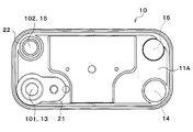
- the heat exchanger 10 shown in FIGS. 1 and 2 constitutes a refrigeration cycle of a vehicle air conditioner.
- the heat exchanger 10 is a condenser that condenses the high-pressure side refrigerant by exchanging heat between the high-pressure side refrigerant of the refrigeration cycle and cooling water (a heat medium having a pressure lower than that of the high-pressure side refrigerant), or cooling with the low-pressure side refrigerant of the refrigeration cycle.
- This is an evaporator that exchanges heat with water (a heat medium having a pressure lower than that of the low-pressure side refrigerant) to evaporate the low-pressure side refrigerant.
- cooling water for example, a liquid containing at least ethylene glycol, dimethylpolysiloxane or nanofluid, or an antifreeze liquid can be used.
- ethylene glycol antifreeze (LLC) is used as the cooling water.
- the heat exchanger 10 is integrally formed by laminating and joining a large number of plate-like members 11.
- the laminating direction of the plate-like member 11 (vertical direction in the example of FIG. 1) is referred to as the plate laminating direction
- one end side in the plate laminating direction (the upper end side in the example of FIG. 1) is referred to as one end side of the plate laminating direction
- the other end side in the plate stacking direction (the lower end side in the example of FIG. 1) is referred to as the other end side in the plate stacking direction.
- the plate-like member 11 is an elongated, substantially rectangular plate material.
- a specific material for example, a double-sided clad material in which a brazing material is clad on both surfaces of an aluminum core material is used.
- an overhanging portion 111 is formed that protrudes in a substantially plate lamination direction (in other words, a direction substantially orthogonal to the plate surface of the plate-like member 11).
- Many plate-like members 11 are joined to each other by brazing in a state where the plate-like members 11 are laminated with each other.
- the multiple plate-like members 11 are arranged so that the protruding tips of the overhanging portions 111 face the same side (substantially downward in the example of FIG. 1).
- a large number of plate-like members 11 form a heat exchanging portion 12, a refrigerant first tank space 13, a refrigerant second tank space 14, a cooling water first tank space 15, and a cooling water second tank space 16. Yes.
- the heat exchange unit 12 includes a plurality of refrigerant channels 121 and a plurality of cooling water channels 122.
- the plurality of refrigerant channels 121 and the plurality of heat medium channels are formed between a large number of plate-like members 11.
- the longitudinal directions of the refrigerant flow path 121 and the cooling water flow path 122 coincide with the longitudinal direction of the plate-like member 11.
- the refrigerant channel 121 and the cooling water channel 122 are alternately stacked one by one in the plate stacking direction (in parallel).
- the plate-like member 11 serves as a partition wall that partitions the coolant channel 121 and the cooling water channel 122. Heat exchange between the refrigerant flowing through the refrigerant flow path 121 and the cooling water flowing through the cooling water flow path 122 is performed via the plate-like member 11.
- the cooling water flows through the flow path 122A located closest to one end in the plate stacking direction among the refrigerant flow path 121 and the cooling water flow path 122 formed in the heat exchange section 12.
- the first outermost cooling water passage 122A (first outermost heat medium passage) located closest to one end in the plate stacking direction is a large number of sheets constituting the heat exchange unit 12.
- the plate-like member 11 is formed between the first endmost plate-like member 11 ⁇ / b> A located closest to one end side in the plate stacking direction and the one end-side plate-like member 11 ⁇ / b> B adjacent to the first endmost plate-like member 11. .
- the first outermost coolant channel 122A is disposed closer to the one end side in the plate stacking direction than the first outermost coolant channel 121A located closest to the one end side in the plate stacking direction among the plurality of refrigerant channels 121. Become.
- the heat exchange performance between the refrigerant and the cooling water can be improved as compared with the case where the first endmost cooling water flow path 122A is not disposed at one end side in the plate stacking direction with respect to the first endmost refrigerant flow path 121.
- the cooling water flows through the flow path 122B located at the other end side in the plate stacking direction among the refrigerant flow path 121 and the cooling water flow path 122 formed in the heat exchange section 12.
- the second outermost cooling water passage 122B (second outermost heat medium passage) located closest to the other end side in the plate stacking direction is a large number constituting the heat exchange unit 12. Formed between the second outermost plate member 11C located closest to the other end side in the plate stacking direction of the plate members 11 and the other end plate member 11D adjacent to the second outermost plate member 11C. Has been.
- the second endmost cooling water flow path 122B is disposed on the other end side in the plate stacking direction with respect to the second endmost refrigerant flow path 121B located closest to the other end side in the plate stacking direction among the plurality of refrigerant flow paths 121. It will be.
- the heat exchange performance between the refrigerant and the cooling water can be improved as compared with the case where the second endmost cooling water flow path 122B is not disposed on the other end side in the plate stacking direction with respect to the second most end refrigerant flow path 121B.
- the first tank space for refrigerant 13 and the first tank space for cooling water 15 are arranged on one side (left side in the example of FIG. 1) of the refrigerant flow path 121 and the cooling water flow path 122 with respect to the heat exchange unit 12.
- the second tank space for refrigerant 14 and the second tank space for cooling water 16 are arranged on the other side (right side in the example of FIG. 1) of the refrigerant flow path 121 and the cooling water flow path 122 with respect to the heat exchange unit 12.
- the first tank space for refrigerant 13 and the second tank space for refrigerant 14 distribute and collect the refrigerant with respect to the plurality of refrigerant flow paths 121.
- the first tank space for cooling water 15 and the second tank space for cooling water 16 distribute and collect the cooling water to the plurality of cooling water flow paths 122.
- the first tank space 13 for refrigerant, the second tank space 14 for refrigerant, the first tank space 15 for cooling water, and the second tank space 16 for cooling water are at the four corners of the plate-like member 11 (in the example of FIG. It is comprised by the communicating hole formed in the four corners.
- the first joint 21 and the first cooling water pipe 22 are attached to the first endmost plate member 11A.
- the first joint 21 is a member for joining refrigerant pipes, and forms the refrigerant inlet 101 of the heat exchanger 10.
- the first cooling water pipe 22 forms the cooling water outlet 102 of the heat exchanger 10.
- a second joint 23 and a second cooling water pipe 24 are attached to the second endmost plate member 11B.
- the second joint 23 is a member for joining refrigerant pipes and forms the refrigerant outlet 103 of the heat exchanger 10.
- the second cooling water pipe 24 forms the cooling water inlet 104 of the heat exchanger 10.
- the refrigerant inlet 101 and the refrigerant outlet 103 communicate with the first refrigerant tank space 13.
- the cooling water outlet 102 and the cooling water inlet 104 communicate with the first tank space 15 for cooling water.
- the first tank space 13 for refrigerant is partitioned into two spaces in the plate stacking direction. Therefore, as shown by the solid line arrow in FIG. 1, the refrigerant flowing from the refrigerant inlet 101 passes through the refrigerant flow paths 121 and 121A on one end side in the plate stacking direction from the refrigerant first tank space 13 side to the refrigerant second tank space 14. After flowing toward the side, the refrigerant flow paths 121 and 121B on the other end side in the plate stacking direction flow from the refrigerant second tank space 14 side toward the refrigerant first tank space 13 side and flow out from the refrigerant outlet 103. . That is, the heat exchanger 10 is configured such that the refrigerant flow makes a U-turn once.
- the first tank space 15 for cooling water is divided into two spaces in the plate stacking direction. Therefore, as shown by the one-dot chain line arrow in FIG. 1, the cooling water flowing from the cooling water inlet 104 passes through the cooling water flow paths 122 and 122B on the other end side in the plate stacking direction from the cooling water first tank space 15 side. After flowing toward the second tank space 16 side, the cooling water flow paths 122 and 122A on one end side in the plate stacking direction flow from the second tank space 16 side for cooling water toward the first tank space 15 side for cooling water. And flows out from the cooling water outlet 102. That is, the heat exchanger 10 is configured so that the flow of the cooling water makes a U-turn once.
- the heat exchanger 10 is configured such that the refrigerant flow and the cooling water flow are in opposite directions (opposite flow).
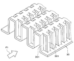
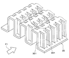
- the offset fins 30 shown in FIG. 3 are arranged between the plate-like members 11.
- the offset fins 30 are inner fins that are interposed between the plate-like members 11 and promote heat exchange between the refrigerant and the heat medium.
- the offset fin 30 is a plate-like member in which a cut and raised portion 301 that is partially cut and raised is formed. A large number of cut-and-raised portions 301 are formed in a direction F1 (that is, the longitudinal direction of the plate-like member 11) parallel to the flow direction of the refrigerant and the cooling water.
- cut-and-raised portions 301 adjacent to each other in the direction F1 parallel to the flow direction of the refrigerant and the cooling water are offset from each other.
- the large number of cut-and-raised parts 301 are staggered in a direction F1 parallel to the flow direction of the refrigerant and the cooling water.
- the offset fin 30 As a specific material of the offset fin 30, for example, a double-sided clad material in which a brazing material is clad on both sides of an aluminum core is used.
- the offset fins 30 are joined to both adjacent plate-like members 11 by brazing.
- the offset fin 30 constitutes an inner wall that joins the adjacent plate-like members 11 and crosses the coolant channel 121 and the cooling water channel 122 in the plate stacking direction.
- the offset fins 30 provided in the first outermost cooling water channel 122A are more than the offset fins 30 provided in the other cooling water channels 122 except for the second outermost cooling water channel 122B among the plurality of cooling water channels 122. It has a part with a large plate thickness.
- the offset fins 30 provided in the first outermost cooling water channel 122A are offset fins 30 provided in other cooling water channels 122 excluding the second outermost cooling water channel 122B among the plurality of cooling water channels 122. It is formed with the board
- the strength of the part forming the first endmost cooling water flow path 122A in the heat exchange unit 12 can be made stronger than the part forming the other cooling water flow path 122. For this reason, the pressure resistance with respect to a refrigerant pressure is securable.
- the offset fins 30 provided in the second outermost cooling water channel 122B are more than the offset fins 30 provided in the cooling water channels 122 other than the first outermost cooling water channel 122A among the plurality of cooling water channels 122. It has a part with a large plate thickness.
- the offset fins 30 provided in the second outermost cooling water channel 122B are compared with the offset fins 30 provided in other cooling water channels 122 other than the first outermost cooling water channel 122A among the plurality of cooling water channels 122. And it is formed with the board
- the strength of the part forming the second endmost cooling water flow path 122B in the heat exchange unit 12 can be made stronger than the part forming the other cooling water flow path 122. For this reason, the pressure resistance with respect to a refrigerant pressure is securable.
- the first endmost cooling water flow path 122A is formed between the first endmost plate-like member 11A and the one end side plate-like member 11B, the first endmost cooling water flow path 122A In the exchange part 12, it will form in the site
- the cooling water flow path 122A is arranged at one end side in the plate stacking direction from the refrigerant flow path 121, compared with the case where the cooling water flow path 122A is not arranged at one end side in the plate stacking direction from the refrigerant flow path 121.
- the heat exchange performance between the refrigerant and the cooling water can be improved.
- the offset fin 30 provided in the first endmost cooling water flow path 122A has a portion having a larger plate thickness than the offset fin 30 provided in the other cooling water flow path 122, the heat exchange unit 12 Among them, the strength of the portion forming the first outermost cooling water flow channel 122A can be made stronger than the portion forming the other cooling water flow channel 122. For this reason, the pressure resistance with respect to a refrigerant pressure is securable.
- the offset fins 30 are provided in the first endmost cooling water flow path 122A, the distribution of cooling water can be improved.
- the 2nd most end cooling water flow path 122B is formed between the 2nd most end plate-like member 11B and the other end side plate-like member 11B, the 2nd most end cooling water flow path 122B It will be formed in the heat exchange part 12 in the site
- the cooling water flow path 122B is disposed on the other end side in the plate stacking direction from the refrigerant flow path 121, the cooling water flow path 122B is not disposed on the other end side in the plate stacking direction from the refrigerant flow path 121. In comparison, the heat exchange performance between the refrigerant and the cooling water can be improved.
- the offset fin 30 provided in the second endmost cooling water flow path 122B has a portion having a larger plate thickness than the offset fins 30 provided in the other cooling water flow paths 122.
- the strength of the portion forming the second endmost cooling water flow passage 122B can be made stronger than the portion forming the other cooling water flow passage 122. For this reason, the pressure
- the offset fins 30 are provided in the second endmost cooling water flow path 122B, the distribution of cooling water can be improved.
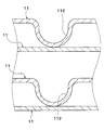
- the rib 112 is formed in a groove shape extending in a direction inclined with respect to the longitudinal direction of the plate-like member 11.
- the ribs 112 are driven out from both ends of the plate stacking direction toward the center. That is, the rib 112 is driven out from the one end side in the plate stacking direction toward the other end side in the portion on the one end side in the plate stacking direction of the heat exchange unit 12. At the other end of the heat exchanging portion 12 in the plate stacking direction, the rib 112 is driven out from the other end in the plate stacking direction toward the one end.
- the rib 112 provided in the first outermost cooling water channel 122A is thicker than the ribs 112 provided in the other cooling water channels 122 other than the second outermost cooling water channel 122B among the plurality of cooling water channels 122. It has a large part.
- the first endmost plate-like member 11A that forms the first endmost cooling water flow path 122A is formed with the other cooling water flow paths 122 other than the second endmost cooling water flow path 122B among the plurality of cooling water flow paths 122.
- the plate member 11 having a plate thickness larger than that of the plate-like member 11, the plate thickness of the rib 112 provided in the first outermost cooling water channel 122 ⁇ / b> A is set to the second outermost cooling water channel 122. It is larger than the plate thickness of the rib 112 provided in the other cooling water flow paths 122 excluding the cooling water flow path 122B.
- the strength of the part forming the first endmost cooling water flow path 122A in the heat exchange unit 12 can be made stronger than the part forming the other cooling water flow path 122. For this reason, the pressure resistance with respect to a refrigerant pressure is securable.
- the rib 112 provided in the second outermost cooling water flow path 122B is thicker than the rib 112 provided in the other cooling water flow paths 122 other than the first outermost cooling water flow path 122A among the plurality of cooling water flow paths 122. It has a large part.
- the second endmost plate-like member 11B that forms the second endmost cooling water flow path 122B is formed into a plate shape that forms the other cooling water flow paths 122 excluding the most end cooling water flow path 122A among the plurality of cooling water flow paths 122.
- the plate thickness of the rib 112 provided in the second endmost cooling water channel 122 ⁇ / b> B is changed to the endmost cooling water channel 122 ⁇ / b> A among the plurality of cooling water channels 122. It is made larger than the plate
- the strength of the part forming the second endmost cooling water flow path 122B in the heat exchange unit 12 can be made stronger than the part forming the other cooling water flow path 122. For this reason, the pressure resistance with respect to a refrigerant pressure is securable.
- the inner wall is constituted by the ribs 112 formed by stamping on the plate-like member 11. Therefore, since the inner wall can be formed without using a member separate from the plate-like member 11, the configuration can be simplified.
- the rib 112 has a circular planar shape.
- a portion of the offset fin 30 corresponding to the rib 112 is cut out to form a through hole.
- the cut-and-raised portion 301 is formed on the entire offset fin 30, but in reality, a region surrounded by a two-dot chain line in FIG. 7 (part corresponding to the rib 112).
- the through hole is formed by cutting out the hole.
- the rib 112 of the plate-like member 11 is arranged in a portion where the through-hole is formed (the portion that is hollowed out) in the offset fin 30, and the rib 112 and the offset fin 30. Interference with is avoided.
- the offset fin 30 and the rib 112 constitute an inner wall. According to this, as compared with the case where only one of the offset fin 30 and the rib 112 is provided, the pressure resistance against the refrigerant pressure can be further ensured. Furthermore, the distribution of cooling water can be improved by the offset fins 30.
- the refrigerant flow paths 121 and the cooling water flow paths 122 are alternately stacked one by one in the plate stacking direction.
- a plurality of refrigerant flow paths 121 and cooling water flow paths 122 are provided in the plate stacking direction.
- the layers may be alternately stacked.
- a refrigerant flow path through which the refrigerant flows may be formed outside the heat exchange unit 12.
- a refrigerant flow path through which the refrigerant flowing into the heat exchange unit 12 flows may be formed on one end side in the plate stack direction with respect to the heat exchange unit 12.
- a refrigerant channel through which the refrigerant that has flowed out of the heat exchange unit 12 flows may be formed on the other end side in the plate stack direction than the heat exchange unit 12.
- the heat exchanger 10 is configured such that the refrigerant flow and the cooling water flow make a U-turn once, but the refrigerant flow and the cooling water flow are configured not to make a U-turn.
- the refrigerant flow and the cooling water flow may be U-turned a plurality of times.
- the heat exchanger 10 is configured such that the refrigerant flow and the cooling water flow are in opposite directions (opposite flow), but the refrigerant flow and the cooling water flow are the same. You may be comprised so that it may become a direction (parallel flow).
- cooling water is used as the heat medium, but various media such as oil may be used as the heat medium.
- Nanofluid may be used as the heat medium.
- a nanofluid is a fluid in which nanoparticles having a particle size of the order of nanometers are mixed.
- antifreeze liquid ethylene glycol
- the effect of improving the thermal conductivity in a specific temperature range the effect of increasing the heat capacity of the heat medium, the effect of preventing the corrosion of metal pipes and the deterioration of rubber pipes, and the heat medium at an extremely low temperature
- liquidity of can be acquired.
- Such an effect varies depending on the particle configuration, particle shape, blending ratio, and additional substance of the nanoparticles.
- the thermal conductivity can be improved, it is possible to obtain the same cooling efficiency even with a small amount of heat medium as compared with the cooling water using ethylene glycol.
- the amount of heat stored in the heat medium itself can be increased.
- the aspect ratio of the nanoparticles is preferably 50 or more. This is because sufficient thermal conductivity can be obtained.
- the aspect ratio is a shape index representing the length ⁇ width of the nanoparticles, in other words, the ratio of the long side to the short side.
- Nanoparticles containing any of Au, Ag, Cu and C can be used. Specifically, Au nanoparticle, Ag nanowire, CNT (carbon nanotube), graphene, graphite core-shell nanoparticle (a structure such as a carbon nanotube surrounding the above atom is included as a constituent atom of the nanoparticle. Particles), Au nanoparticle-containing CNTs, and the like can be used.
Landscapes
- Engineering & Computer Science (AREA)
- Physics & Mathematics (AREA)
- Thermal Sciences (AREA)
- Mechanical Engineering (AREA)
- General Engineering & Computer Science (AREA)
- Heat-Exchange Devices With Radiators And Conduit Assemblies (AREA)
Abstract
熱交換器は、冷媒と、前記冷媒よりも低圧の熱媒体とを熱交換させる熱交換部(12)を備える。多数枚の板状部材(11)同士の間には、前記冷媒が流れる複数の冷媒流路(121)、および前記熱媒体が流れる複数の熱媒体流路(122)が形成される。前記複数の熱媒体流路(122)には、隣り合う前記板状部材(11)同士を接合し、かつ前記熱媒体流路(122)を前記積層方向に横断する内部壁(30、112)が設けられている。前記複数の熱媒体流路(122)のうち前記積層方向において最も一端側に位置する第1最端熱媒体流路(122A)に設けられた前記内部壁は、前記複数の熱媒体流路(122)のうち前記積層方向において最も他端側に位置する第2最端熱媒体流路(122B)を除く他の前記熱媒体流路(122)に設けられた前記内部壁(30、112)よりも板厚の大きい部位を有している。
Description
本出願は、2013年7月31日に出願された日本出願番号2013-158936号に基づくもので、ここにその記載内容を援用する。
本開示は、冷媒と、冷媒よりも低圧の熱媒体とを熱交換する熱交換器に関する。
特許文献1には、冷媒と水とを熱交換させる水/冷媒熱交換器が記載されている。複数の略平板状の伝熱プレートを間隔をおいて重ね合わせることにより伝熱プレート間に冷媒流路と水流路とを交互に形成している。一般的に、この種の水/冷媒熱交換器においては、冷媒は水よりも高圧になっている。
上記水/冷媒熱交換器と、水と空気とを熱交換させる水/空気熱交換器とを用いて、冷媒と空気と熱交換させる熱交換システムを構成する場合、水/冷媒熱交換器における冷媒と水との温度差は、冷媒と空気との温度差と比較して小さくなる。
そのため、この熱交換システムにおける水/冷媒熱交換器では、冷媒と空気とを熱交換させる空気/冷媒熱交換器を用いる場合と比較して、冷媒を確実に熱交換させるのが困難になる。その結果、水/冷媒熱交換器の出口冷媒の状態が、空気/冷媒熱交換器の出口冷媒の状態と比較して不安定になりやすい。すなわち、水/冷媒熱交換器の出口冷媒は、空気/冷媒熱交換器の出口冷媒と比較して、気液2相状態と単相状態とが入り混じった状態になりやすい。
また、上記水/冷媒熱交換器においては、冷媒の圧力に対する耐圧性を確保できる構造にする必要がある。
本開示は、冷媒と、冷媒よりも低圧の熱媒体とを熱交換する熱交換器において、冷媒と熱媒体との熱交換性能を向上させるとともに、冷媒の圧力に対する耐圧性を確保することを目的とする。
本開示の一形態では、熱交換器は、冷媒と、冷媒よりも低圧の熱媒体とを熱交換させる熱交換部を備える。熱交換部は、多数枚の板状部材が互いに積層されて接合されることによって形成されている。多数枚の板状部材同士の間には、冷媒が流れる複数の冷媒流路、および熱媒体が流れる複数の熱媒体流路が形成される。複数の冷媒流路および複数の熱媒体流路は、多数枚の板状部材の積層方向に並んで配置されている。複数の熱媒体流路には、隣り合う板状部材同士を接合し、かつ熱媒体流路を積層方向に横断する内部壁が設けられている。複数の熱媒体流路のうち板状部材の積層方向において最も一端側に位置する第1最端熱媒体流路は、多数枚の板状部材のうち板状部材の積層方向において最も一端側に位置する第1最端板状部材と、多数枚の板状部材のうち第1最端板状部材に隣接する一端側板状部材との間に形成されている。第1最端熱媒体流路に設けられた内部壁は、複数の熱媒体流路のうち板状部材の積層方向において最も他端側に位置する第2最端熱媒体流路を除く他の熱媒体流路に設けられた内部壁よりも板厚の大きい部位を有している。
これによると、第1最端熱媒体流路は第1最端板状部材と一端側板状部材との間に形成されているので、第1最端熱媒体流路は、熱交換部のうち板状部材の積層方向において最も一端側の部位に形成されることとなる。
したがって、冷媒流路よりも板状部材の積層方向における一端側に熱媒体流路が配置されることとなるので、冷媒流路よりも板状部材の積層方向における一端側に熱媒体流路が配置されない場合と比較して、冷媒と熱媒体との熱交換性能を向上できる。
さらに、第1最端熱媒体流路に設けられた内部壁は、他の熱媒体流路に設けられた内部壁よりも板厚の大きい部位を有しているので、熱交換部のうち第1最端熱媒体流路を形成する部位の強度を、他の熱媒体冷却水流路を形成する部位よりも強くできる。このため、冷媒圧力に対する耐圧性を確保できる。
以下、実施形態について図に基づいて説明する。なお、以下の各実施形態相互において、互いに同一もしくは均等である部分には、図中、同一符号を付してある。
(第1実施形態)
図1、図2に示す熱交換器10は、車両用空調装置の冷凍サイクルを構成している。熱交換器10は、冷凍サイクルの高圧側冷媒と冷却水(高圧側冷媒よりも低圧の熱媒体)とを熱交換して高圧側冷媒を凝縮させる凝縮器、または冷凍サイクルの低圧側冷媒と冷却水(低圧側冷媒よりも低圧の熱媒体)とを熱交換して低圧側冷媒を蒸発させる蒸発器である。
図1、図2に示す熱交換器10は、車両用空調装置の冷凍サイクルを構成している。熱交換器10は、冷凍サイクルの高圧側冷媒と冷却水(高圧側冷媒よりも低圧の熱媒体)とを熱交換して高圧側冷媒を凝縮させる凝縮器、または冷凍サイクルの低圧側冷媒と冷却水(低圧側冷媒よりも低圧の熱媒体)とを熱交換して低圧側冷媒を蒸発させる蒸発器である。
冷却水としては、例えば、少なくともエチレングリコール、ジメチルポリシロキサンもしくはナノ流体を含む液体、または不凍液体等を用いることができる。本実施形態では、冷却水として、エチレングリコール系の不凍液(LLC)が用いられている。
熱交換器10は、多数の板状部材11が積層されて接合されることによって一体的に形成されている。以下では、板状部材11の積層方向(図1の例では上下方向)を板積層方向と言い、板積層方向の一端側(図1の例では上端側)を板積層方向一端側と言い、板積層方向の他端側(図1の例では下端側)を板積層方向他端側と言う。
板状部材11は細長の略矩形状の板材であり、具体的材質としては、例えば、アルミニウム心材の両面にろう材をクラッドした両面クラッド材が用いられる。
略矩形状の板状部材11の外周縁部には、略板積層方向(換言すれば、板状部材11の板面と略直交する方向)に突出する張出部111が形成されている。多数の板状部材11は、互いに積層された状態で張出部111同士がろう付けにより接合されている。
多数の板状部材11は、張出部111の突出先端が互いに同じ側(図1の例では略下方側)を向くように配置されている。
多数の板状部材11は、熱交換部12、冷媒用第1タンク空間13、冷媒用第2タンク空間14、冷却水用第1タンク空間15および冷却水用第2タンク空間16を形成している。熱交換部12は、複数の冷媒流路121および複数の冷却水流路122で構成されている。
複数の冷媒流路121および複数の熱媒体流路は、多数枚の板状部材11同士の間に形成されている。冷媒流路121および冷却水流路122の長手方向は、板状部材11の長手方向と一致している。
冷媒流路121および冷却水流路122は板積層方向に1本ずつ交互に積層配置(並列配置)されている。板状部材11は、冷媒流路121と冷却水流路122とを仕切る隔壁の役割を果たしている。冷媒流路121を流れる冷媒と、冷却水流路122を流れる冷却水との熱交換は、板状部材11を介して行われる。
熱交換部12に形成される冷媒流路121および冷却水流路122のうち最も板積層方向一端側に位置する流路122Aには、冷却水が流れるようになっている。
換言すれば、複数の冷却水流路122のうち最も板積層方向一端側に位置する第1最端冷却水流路122A(第1最端熱媒体流路)は、熱交換部12を構成する多数枚の板状部材11のうち最も板積層方向一端側に位置する第1最端板状部材11Aと、第1最端板状部材11に隣接する一端側板状部材11Bとの間に形成されている。
したがって、複数の冷媒流路121のうち最も板積層方向一端側に位置する第1最端冷媒流路121Aよりも板積層方向一端側に、第1最端冷却水流路122Aが配置されることとなる。
そのため、第1最端冷媒流路121よりも板積層方向一端側に第1最端冷却水流路122Aが配置されない場合と比較して、冷媒と冷却水との熱交換性能を向上できる。
熱交換部12に形成される冷媒流路121および冷却水流路122のうち最も板積層方向他端側に位置する流路122Bには、冷却水が流れるようになっている。
換言すれば、複数の冷却水流路122のうち最も板積層方向他端側に位置する第2最端冷却水流路122B(第2最端熱媒体流路)は、熱交換部12を構成する多数枚の板状部材11のうち最も板積層方向他端側に位置する第2最端板状部材11Cと、第2最端板状部材11Cに隣接する他端側板状部材11Dとの間に形成されている。
したがって、複数の冷媒流路121のうち最も板積層方向他端側に位置する第2最端冷媒流路121Bよりも板積層方向他端側に、第2最端冷却水流路122Bが配置されることとなる。
そのため、第2最端冷媒流路121Bよりも板積層方向他端側に第2最端冷却水流路122Bが配置されない場合と比較して、冷媒と冷却水との熱交換性能を向上できる。
冷媒用第1タンク空間13および冷却水用第1タンク空間15は、熱交換部12に対して、冷媒流路121および冷却水流路122の一方側(図1の例では左方側)に配置されている。冷媒用第2タンク空間14および冷却水用第2タンク空間16は、熱交換部12に対して、冷媒流路121および冷却水流路122の他方側(図1の例では右方側)に配置されている。
冷媒用第1タンク空間13および冷媒用第2タンク空間14は、複数の冷媒流路121に対して冷媒の分配および集合を行う。冷却水用第1タンク空間15および冷却水用第2タンク空間16は、複数の冷却水流路122に対して冷却水の分配および集合を行う。
冷媒用第1タンク空間13、冷媒用第2タンク空間14、冷却水用第1タンク空間15および冷却水用第2タンク空間16は、板状部材11の四隅(図2の例では上下左右の四隅)に形成された連通孔によって構成されている。
第1最端板状部材11Aには、第1ジョイント21および第1冷却水パイプ22が取り付けられている。第1ジョイント21は、冷媒配管を接合するための部材であり、熱交換器10の冷媒入口101を形成している。第1冷却水パイプ22は、熱交換器10の冷却水出口102を形成している。
第2最端板状部材11Bには、第2ジョイント23および第2冷却水パイプ24が取り付けられている。第2ジョイント23は、冷媒配管を接合するための部材であり、熱交換器10の冷媒出口103を形成している。第2冷却水パイプ24は、熱交換器10の冷却水入口104を形成している。
冷媒入口101および冷媒出口103は冷媒用第1タンク空間13に連通している。冷却水出口102および冷却水入口104は冷却水用第1タンク空間15に連通している。
冷媒用第1タンク空間13は板積層方向に2つの空間に仕切られている。したがって、図1の実線矢印に示すように、冷媒入口101から流入した冷媒は、板積層方向一端側の冷媒流路121、121Aを冷媒用第1タンク空間13側から冷媒用第2タンク空間14側へ向かって流れた後、板積層方向他端側の冷媒流路121、121Bを冷媒用第2タンク空間14側から冷媒用第1タンク空間13側へ向かって流れて冷媒出口103から流出する。すなわち、熱交換器10は、冷媒の流れが1回Uターンするように構成されている。
同様に、冷却水用第1タンク空間15は板積層方向に2つの空間に仕切られている。したがって、図1の一点鎖線矢印に示すように、冷却水入口104から流入した冷却水は、板積層方向他端側の冷却水流路122、122Bを冷却水用第1タンク空間15側から冷却水用第2タンク空間16側へ向かって流れた後、板積層方向一端側の冷却水流路122、122Aを冷却水用第2タンク空間16側から冷却水用第1タンク空間15側へ向かって流れて冷却水出口102から流出する。すなわち、熱交換器10は、冷却水の流れが1回Uターンするように構成されている。
熱交換器10は、冷媒の流れと冷却水の流れとが互いに反対方向(対向流)になるように構成されている。
板状部材11同士の間には、図3に示すオフセットフィン30が配置されている。オフセットフィン30は、板状部材11同士の間に介在し、冷媒と熱媒体との間での熱交換を促進させるインナーフィンである。
オフセットフィン30は、部分的に切り起こされた切り起こし部301が形成された板状の部材である。切り起こし部301は、冷媒および冷却水の流れ方向と平行な方向F1(すなわち、板状部材11の長手方向)に多数個形成されている。
冷媒および冷却水の流れ方向と平行な方向F1に隣り合う切り起こし部301同士は、互いにオフセットされている。図3の例では、多数個の切り起こし部301は、冷媒および冷却水の流れ方向と平行な方向F1に千鳥配置されている。
オフセットフィン30の具体的材質としては、例えば、アルミニウム心材の両面にろう材をクラッドした両面クラッド材が用いられる。オフセットフィン30は、隣り合う両方の板状部材11にろう付けにより接合されている。
したがって、オフセットフィン30は、隣り合う板状部材11同士を接合し、かつ冷媒流路121および冷却水流路122を板積層方向に横断する内部壁を構成している。
第1最端冷却水流路122Aに設けられたオフセットフィン30は、複数の冷却水流路122のうち第2最端冷却水流路122Bを除く他の冷却水流路122に設けられたオフセットフィン30よりも板厚の大きい部位を有している。
例えば、第1最端冷却水流路122Aに設けられたオフセットフィン30は、複数の冷却水流路122のうち第2最端冷却水流路122Bを除く他の冷却水流路122に設けられたオフセットフィン30と比較して板厚の大きい板材で形成されている。
これにより、熱交換部12のうち第1最端冷却水流路122Aを形成する部位の強度を、他の冷却水流路122を形成する部位よりも強くできる。このため、冷媒圧力に対する耐圧性を確保できる。
第2最端冷却水流路122Bに設けられたオフセットフィン30は、複数の冷却水流路122のうち第1最端冷却水流路122Aを除く他の冷却水流路122に設けられたオフセットフィン30よりも板厚の大きい部位を有している。
第2最端冷却水流路122Bに設けられたオフセットフィン30は、複数の冷却水流路122のうち第1最端冷却水流路122Aを除く他の冷却水流路122に設けられたオフセットフィン30と比較して板厚の大きい板材で形成されている。
これにより、熱交換部12のうち第2最端冷却水流路122Bを形成する部位の強度を、他の冷却水流路122を形成する部位よりも強くできる。このため、冷媒圧力に対する耐圧性を確保できる。
本実施形態によると、第1最端冷却水流路122Aは第1最端板状部材11Aと一端側板状部材11Bとの間に形成されているので、第1最端冷却水流路122Aは、熱交換部12のうち最も板積層方向一端側の部位に形成されることとなる。
したがって、冷媒流路121よりも板積層方向一端側に冷却水流路122Aが配置されることとなるので、冷媒流路121よりも板積層方向一端側に冷却水流路122Aが配置されない場合と比較して、冷媒と冷却水との熱交換性能を向上できる。
さらに、第1最端冷却水流路122Aに設けられたオフセットフィン30は、他の冷却水流路122に設けられたオフセットフィン30よりも板厚の大きい部位を有しているので、熱交換部12のうち第1最端冷却水流路122Aを形成する部位の強度を、他の冷却水流路122を形成する部位よりも強くできる。このため、冷媒圧力に対する耐圧性を確保できる。
本実施形態によると、第1最端冷却水流路122Aにオフセットフィン30が設けられているので、冷却水の分配性を向上できる。
本実施形態によると、第2最端冷却水流路122Bは第2最端板状部材11Bと他端側板状部材11Bとの間に形成されているので、第2最端冷却水流路122Bは、熱交換部12のうち最も板積層方向他端側の部位に形成されることとなる。
したがって、冷媒流路121よりも板積層方向他端側に冷却水流路122Bが配置されることとなるので、冷媒流路121よりも板積層方向他端側に冷却水流路122Bが配置されない場合と比較して、冷媒と冷却水との熱交換性能を向上できる。
さらに、第2最端冷却水流路122Bに設けられたオフセットフィン30は、他の冷却水流路122に設けられたオフセットフィン30よりも板厚の大きい部位を有しているので、熱交換部12のうち第2最端冷却水流路122Bを形成する部位の強度を、他の冷却水流路122を形成する部位よりも強くできる。このため、冷媒圧力に対する耐圧性を一層確保できる。
本実施形態によると、第2最端冷却水流路122Bにオフセットフィン30が設けられているので、冷却水の分配性を向上できる。
(第2実施形態)
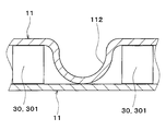
上記第1実施形態では、隣り合う板状部材11同士を接合し、かつ冷媒流路121および冷却水流路122を板積層方向に横断する内部壁をオフセットフィン30によって構成しているが、本実施形態では、図4、図5に示すように、板状部材11に打ち出し成形されたリブ112によって内部壁を構成している。
上記第1実施形態では、隣り合う板状部材11同士を接合し、かつ冷媒流路121および冷却水流路122を板積層方向に横断する内部壁をオフセットフィン30によって構成しているが、本実施形態では、図4、図5に示すように、板状部材11に打ち出し成形されたリブ112によって内部壁を構成している。
図4の例では、リブ112は、板状部材11の長手方向に対して傾いた方向に延びる溝状に形成されている。
リブ112は、板積層方向両端側から中央側に向かって打ち出されている。すなわち、熱交換部12のうち板積層方向一端側の部位では、リブ112は板積層方向一端側から他端側に向かって打ち出されている。熱交換部12のうち板積層方向他端の部位では、リブ112は板積層方向他端側から一端側に向かって打ち出されている。
第1最端冷却水流路122Aに設けられたリブ112は、複数の冷却水流路122のうち第2最端冷却水流路122Bを除く他の冷却水流路122に設けられたリブ112よりも板厚の大きい部位を有している。
例えば、第1最端冷却水流路122Aを形成する第1最端板状部材11Aを、複数の冷却水流路122のうち第2最端冷却水流路122Bを除く他の冷却水流路122を形成する板状部材11と比較して板厚の大きい板材で形成することによって、第1最端冷却水流路122Aに設けられたリブ112の板厚を、複数の冷却水流路122のうち第2最端冷却水流路122Bを除く他の冷却水流路122に設けられたリブ112の板厚よりも大きくしている。
これにより、熱交換部12のうち第1最端冷却水流路122Aを形成する部位の強度を、他の冷却水流路122を形成する部位よりも強くできる。このため、冷媒圧力に対する耐圧性を確保できる。
第2最端冷却水流路122Bに設けられたリブ112は、複数の冷却水流路122のうち第1最端冷却水流路122Aを除く他の冷却水流路122に設けられたリブ112よりも板厚の大きい部位を有している。
例えば、第2最端冷却水流路122Bを形成する第2最端板状部材11Bを、複数の冷却水流路122のうち最一端冷却水流路122Aを除く他の冷却水流路122を形成する板状部材11と比較して板厚の大きい板材で形成することによって、第2最端冷却水流路122Bに設けられたリブ112の板厚を、複数の冷却水流路122のうち最一端冷却水流路122Aを除く他の冷却水流路122に設けられたリブ112の板厚よりも大きくしている。
これにより、熱交換部12のうち第2最端冷却水流路122Bを形成する部位の強度を、他の冷却水流路122を形成する部位よりも強くできる。このため、冷媒圧力に対する耐圧性を確保できる。
本実施形態では、板状部材11に打ち出し成形されたリブ112によって内部壁を構成している。そのため、板状部材11とは別個の部材を用いることなく内部壁を形成することができるので、構成を簡素化できる。
(第3実施形態)
本実施形態では、図6~図8に示すように、上記第1実施形態のオフセットフィン30と、上記第2実施形態のリブ112とを組み合わせている。
本実施形態では、図6~図8に示すように、上記第1実施形態のオフセットフィン30と、上記第2実施形態のリブ112とを組み合わせている。
本実施形態では、図6に示すように、リブ112は平面形状が円形状に形成されている。オフセットフィン30のうちリブ112に対応する部位は、くり抜かれて貫通孔が形成されている。図7では、図示の都合上、オフセットフィン30の全体に切り起こし部301が形成されているが、実際には、図7中、2点鎖線で囲まれた領域(リブ112に対応する部位)がくり抜かれて貫通孔が形成されている。
これにより、図8に示すように、オフセットフィン30のうち貫通孔が形成されている部位(くり抜かれた部位)に板状部材11のリブ112が配置されることとなり、リブ112とオフセットフィン30との干渉が回避される。
本実施形態によると、オフセットフィン30およびリブ112の両方が設けられているので、冷媒圧力に対する耐圧性を一層確保できる。
本実施形態では、オフセットフィン30およびリブ112によって内部壁を構成している。これによると、オフセットフィン30およびリブ112のいずれか一方のみが設けられている場合と比較して、冷媒圧力に対する耐圧性を一層確保できる。さらに、オフセットフィン30によって冷却水の分配性を向上できる。
(他の実施形態)
上記実施形態を例えば以下のように種々変形可能である。
上記実施形態を例えば以下のように種々変形可能である。
上記実施形態では、冷媒流路121および冷却水流路122は板積層方向に1本ずつ交互に積層配置されているが、例えば、冷媒流路121および冷却水流路122は板積層方向に複数本ずつ交互に積層配置されていてもよい。
上記実施形態において、熱交換部12の外部に、冷媒が流れる冷媒流路が形成されていてもよい。例えば、熱交換部12よりも板積方向一端側に、熱交換部12に流入する冷媒が流れる冷媒流路が形成されていてもよい。同様に、熱交換部12よりも板積方向他端側に、熱交換部12から流出した冷媒が流れる冷媒流路が形成されていてもよい。
上記実施形態では、熱交換器10は、冷媒の流れおよび冷却水の流れが1回Uターンするように構成されているが、冷媒の流れおよび冷却水の流れがUターンしないように構成されていてもよいし、冷媒の流れおよび冷却水の流れが複数回Uターンするように構成されてもよい。
上記実施形態では、熱交換器10は、冷媒の流れと冷却水の流れとが互いに反対方向(対向流)になるように構成されているが、冷媒の流れと冷却水の流れとが互いに同じ方向(平行流)になるように構成されていてもよい。
上記実施形態では、熱媒体として冷却水を用いているが、油などの各種媒体を熱媒体として用いてもよい。
熱媒体として、ナノ流体を用いてもよい。ナノ流体とは、粒子径がナノメートルオーダーのナノ粒子が混入された流体のことである。ナノ粒子を熱媒体に混入させることで、エチレングリコールを用いた冷却水(いわゆる不凍液)のように凝固点を低下させる作用効果に加えて、次のような作用効果を得ることができる。
すなわち、特定の温度帯での熱伝導率を向上させる作用効果、熱媒体の熱容量を増加させる作用効果、金属配管の防食効果やゴム配管の劣化を防止する作用効果、および極低温での熱媒体の流動性を高める作用効果を得ることができる。
このような作用効果は、ナノ粒子の粒子構成、粒子形状、配合比率、付加物質によって様々に変化する。
これによると、熱伝導率を向上させることができるので、エチレングリコールを用いた冷却水と比較して少ない量の熱媒体であっても同等の冷却効率を得ることが可能になる。
また、熱媒体の熱容量を増加させることができるので、熱媒体自体の蓄冷熱量(顕熱による蓄冷熱)を増加させることができる。
蓄冷熱量を増加させることにより、冷凍サイクルの圧縮機を作動させない状態であっても、ある程度の時間は蓄冷熱を利用した機器の冷却、加熱の温調が実施できるため、車両用空調装置の省動力化が可能になる。
ナノ粒子のアスペクト比は50以上であるのが好ましい。十分な熱伝導率を得ることができるからである。なお、アスペクト比は、ナノ粒子の縦×横、言い換えれば長辺と短辺の比率を表す形状指標である。
ナノ粒子としては、Au、Ag、CuおよびCのいずれかを含むものを用いることができる。具体的には、ナノ粒子の構成原子として、Auナノ粒子、Agナノワイヤー、CNT(カーボンナノチューブ)、グラフェン、グラファイトコアシェル型ナノ粒子(上記原子を囲むようにカーボンナノチューブ等の構造体があるような粒子体)、およびAuナノ粒子含有CNTなどを用いることができる。
Claims (6)
- 冷媒と、前記冷媒よりも低圧の熱媒体とを熱交換させる熱交換部(12)を備え、
前記熱交換部(12)は、多数枚の板状部材(11)が互いに積層されて接合されることによって形成されており、
前記多数枚の板状部材(11)同士の間には、前記冷媒が流れる複数の冷媒流路(121)、および前記熱媒体が流れる複数の熱媒体流路(122)が形成され、
前記複数の冷媒流路(121)および前記複数の熱媒体流路(122)は、前記多数枚の板状部材(11)の積層方向に並んで配置されており、
前記複数の熱媒体流路(122)には、隣り合う前記板状部材(11)同士を接合し、かつ前記熱媒体流路(122)を前記積層方向に横断する内部壁(30、112)が設けられており、
前記複数の熱媒体流路(122)のうち前記積層方向において最も一端側に位置する第1最端熱媒体流路(122A)は、前記多数枚の板状部材(11)のうち最も前記一端側に位置する第1最端板状部材(11A)と、前記多数枚の板状部材(11)のうち前記第1最端板状部材(11A)に隣接する一端側板状部材(11B)との間に形成されており、
前記第1最端熱媒体流路(122A)に設けられた前記内部壁(30、112)は、前記複数の熱媒体流路(122)のうち前記積層方向において最も他端側に位置する第2最端熱媒体流路(122B)を除く他の前記熱媒体流路(122)に設けられた前記内部壁(30、112)よりも板厚の大きい部位を有している熱交換器。 - 前記内部壁は、前記板状部材(11)同士の間に介在し、前記冷媒と前記熱媒体との間での熱交換を促進させるインナーフィン(30)であり、
前記インナーフィン(30)は、部分的に切り起こされた切り起こし部(301)が前記熱媒体の流れ方向に多数形成され、前記熱媒体の流れ方向に隣り合う前記切り起こし部(301)同士が互いにオフセットされているオフセットフィンである請求項1に記載の熱交換器。 - 前記内部壁は、前記板状部材(11)に打ち出し成形されたリブ(112)である請求項1に記載の熱交換器。
- 前記内部壁は、前記板状部材(11)同士の間に介在し、前記冷媒と前記熱媒体との間での熱交換を促進させるインナーフィン(30)、および隣り合う前記板状部材(11)のうち前記一端側の板状部材(11)に打ち出し成形されたリブ(112)であり、
前記インナーフィン(30)は、部分的に切り起こされた切り起こし部(301)が前記熱媒体の流れ方向に多数形成され、前記熱媒体の流れ方向に隣り合う前記切り起こし部(301)同士が互いにオフセットされているオフセットフィンである請求項1に記載の熱交換器。 - 前記第2最端熱媒体流路(122B)は、前記熱交換部(12)を構成する前記多数枚の板状部材(11)のうち最も前記他端側に位置する第2最端板状部材(11C)と、前記第2最端板状部材(11C)に隣接する他端側板状部材(11D)との間に形成されており、
前記第2最端熱媒体流路(122B)に設けられた前記内部壁(30、112)は、前記複数の熱媒体流路(122)のうち前記第1最端熱媒体流路(122A)を除く他の前記熱媒体流路(122)に設けられた前記内部壁(30、112)よりも板厚の大きい部位を有している請求項1ないし4のいずれか1つに記載の熱交換器。 - 前記熱媒体は、エチレングリコール系の不凍液である請求項1ないし5のいずれか1つに記載の熱交換器。
Applications Claiming Priority (2)
| Application Number | Priority Date | Filing Date | Title |
|---|---|---|---|
| JP2013158936A JP6102612B2 (ja) | 2013-07-31 | 2013-07-31 | 熱交換器 |
| JP2013-158936 | 2013-07-31 |
Publications (1)
| Publication Number | Publication Date |
|---|---|
| WO2015015683A1 true WO2015015683A1 (ja) | 2015-02-05 |
Family
ID=52431249
Family Applications (1)
| Application Number | Title | Priority Date | Filing Date |
|---|---|---|---|
| PCT/JP2014/002943 Ceased WO2015015683A1 (ja) | 2013-07-31 | 2014-06-03 | 熱交換器 |
Country Status (2)
| Country | Link |
|---|---|
| JP (1) | JP6102612B2 (ja) |
| WO (1) | WO2015015683A1 (ja) |
Citations (4)
| Publication number | Priority date | Publication date | Assignee | Title |
|---|---|---|---|---|
| JPH06201287A (ja) * | 1993-01-06 | 1994-07-19 | Ishikawajima Harima Heavy Ind Co Ltd | プレートフィン型熱交換器 |
| JP2000002494A (ja) * | 1998-06-18 | 2000-01-07 | Mitsubishi Electric Corp | プレート式熱交換器および冷凍サイクル装置 |
| JP2007183071A (ja) * | 2006-01-10 | 2007-07-19 | Tokyo Bureizu Kk | 高耐圧コンパクト熱交換器およびその製造法 |
| WO2012105888A1 (en) * | 2011-02-04 | 2012-08-09 | Alfa Laval Corporate Ab | A plate heat exchanger |
Family Cites Families (2)
| Publication number | Priority date | Publication date | Assignee | Title |
|---|---|---|---|---|
| JP2984480B2 (ja) * | 1992-10-09 | 1999-11-29 | 三菱重工業株式会社 | 積層型熱交換器 |
| US7343965B2 (en) * | 2004-01-20 | 2008-03-18 | Modine Manufacturing Company | Brazed plate high pressure heat exchanger |
-
2013
- 2013-07-31 JP JP2013158936A patent/JP6102612B2/ja active Active
-
2014
- 2014-06-03 WO PCT/JP2014/002943 patent/WO2015015683A1/ja not_active Ceased
Patent Citations (4)
| Publication number | Priority date | Publication date | Assignee | Title |
|---|---|---|---|---|
| JPH06201287A (ja) * | 1993-01-06 | 1994-07-19 | Ishikawajima Harima Heavy Ind Co Ltd | プレートフィン型熱交換器 |
| JP2000002494A (ja) * | 1998-06-18 | 2000-01-07 | Mitsubishi Electric Corp | プレート式熱交換器および冷凍サイクル装置 |
| JP2007183071A (ja) * | 2006-01-10 | 2007-07-19 | Tokyo Bureizu Kk | 高耐圧コンパクト熱交換器およびその製造法 |
| WO2012105888A1 (en) * | 2011-02-04 | 2012-08-09 | Alfa Laval Corporate Ab | A plate heat exchanger |
Also Published As
| Publication number | Publication date |
|---|---|
| JP6102612B2 (ja) | 2017-03-29 |
| JP2015031412A (ja) | 2015-02-16 |
Similar Documents
| Publication | Publication Date | Title |
|---|---|---|
| JP6504367B2 (ja) | 熱交換器 | |
| CN203464829U (zh) | 热交换器用联管箱及具有该热交换器用联管箱的热交换器 | |
| WO2014132602A1 (ja) | 積層型熱交換器 | |
| WO2015178005A1 (ja) | 積層型熱交換器 | |
| JP2019215154A (ja) | 空調回路のための冷媒供給源を伴うコンデンサ | |
| JP6578964B2 (ja) | 積層型熱交換器 | |
| JP6528283B2 (ja) | 熱交換器 | |
| JP6183100B2 (ja) | 蓄冷熱交換器 | |
| JP2015059669A (ja) | 積層型熱交換器 | |
| WO2015046275A1 (ja) | 熱交換器及びそれを用いた空気調和機 | |
| CN105229394B (zh) | 制冷剂蒸发器 | |
| US7121331B2 (en) | Heat exchanger | |
| JP2006132805A (ja) | プレート型熱交換器 | |
| JP6578980B2 (ja) | 積層型熱交換器 | |
| WO2016136266A1 (ja) | 冷媒蒸発器 | |
| JP6102612B2 (ja) | 熱交換器 | |
| CN113574332B (zh) | 热交换器 | |
| KR101427931B1 (ko) | 판형 열교환기 | |
| JP2018040513A (ja) | 熱交換器用チューブ及び熱交換器 | |
| WO2017195588A1 (ja) | 積層型熱交換器 | |
| JP6354868B1 (ja) | 水熱交換器 | |
| JP2017045857A (ja) | 冷却器 | |
| JP6281422B2 (ja) | 積層型熱交換器 | |
| JP6613996B2 (ja) | 冷媒蒸発器 | |
| JP2011242089A (ja) | 積層型熱交換器 |
Legal Events
| Date | Code | Title | Description |
|---|---|---|---|
| 121 | Ep: the epo has been informed by wipo that ep was designated in this application |
Ref document number: 14831982 Country of ref document: EP Kind code of ref document: A1 |
|
| NENP | Non-entry into the national phase |
Ref country code: DE |
|
| 122 | Ep: pct application non-entry in european phase |
Ref document number: 14831982 Country of ref document: EP Kind code of ref document: A1 |