WO2015012345A1 - ボイラ用給水予熱システム及びボイラ用給水予熱方法 - Google Patents
ボイラ用給水予熱システム及びボイラ用給水予熱方法 Download PDFInfo
- Publication number
- WO2015012345A1 WO2015012345A1 PCT/JP2014/069541 JP2014069541W WO2015012345A1 WO 2015012345 A1 WO2015012345 A1 WO 2015012345A1 JP 2014069541 W JP2014069541 W JP 2014069541W WO 2015012345 A1 WO2015012345 A1 WO 2015012345A1
- Authority
- WO
- WIPO (PCT)
- Prior art keywords
- boiler
- water
- feed water
- heat
- boiler feed
- Prior art date
- Legal status (The legal status is an assumption and is not a legal conclusion. Google has not performed a legal analysis and makes no representation as to the accuracy of the status listed.)
- Ceased
Links
Images

Classifications
-
- F—MECHANICAL ENGINEERING; LIGHTING; HEATING; WEAPONS; BLASTING
- F22—STEAM GENERATION
- F22D—PREHEATING, OR ACCUMULATING PREHEATED, FEED-WATER FOR STEAM GENERATION; FEED-WATER SUPPLY FOR STEAM GENERATION; CONTROLLING WATER LEVEL FOR STEAM GENERATION; AUXILIARY DEVICES FOR PROMOTING WATER CIRCULATION WITHIN STEAM BOILERS
- F22D1/00—Feed-water heaters, i.e. economisers or like preheaters
- F22D1/02—Feed-water heaters, i.e. economisers or like preheaters with water tubes arranged in the boiler furnaces, fire tubes or flue ways
-
- F—MECHANICAL ENGINEERING; LIGHTING; HEATING; WEAPONS; BLASTING
- F01—MACHINES OR ENGINES IN GENERAL; ENGINE PLANTS IN GENERAL; STEAM ENGINES
- F01K—STEAM ENGINE PLANTS; STEAM ACCUMULATORS; ENGINE PLANTS NOT OTHERWISE PROVIDED FOR; ENGINES USING SPECIAL WORKING FLUIDS OR CYCLES
- F01K23/00—Plants characterised by more than one engine delivering power external to the plant, the engines being driven by different fluids
- F01K23/02—Plants characterised by more than one engine delivering power external to the plant, the engines being driven by different fluids the engine cycles being thermally coupled
- F01K23/04—Plants characterised by more than one engine delivering power external to the plant, the engines being driven by different fluids the engine cycles being thermally coupled condensation heat from one cycle heating the fluid in another cycle
-
- F—MECHANICAL ENGINEERING; LIGHTING; HEATING; WEAPONS; BLASTING
- F22—STEAM GENERATION
- F22D—PREHEATING, OR ACCUMULATING PREHEATED, FEED-WATER FOR STEAM GENERATION; FEED-WATER SUPPLY FOR STEAM GENERATION; CONTROLLING WATER LEVEL FOR STEAM GENERATION; AUXILIARY DEVICES FOR PROMOTING WATER CIRCULATION WITHIN STEAM BOILERS
- F22D1/00—Feed-water heaters, i.e. economisers or like preheaters
- F22D1/16—Feed-water heaters, i.e. economisers or like preheaters with water tubes arranged otherwise than in the boiler furnace, fire tubes, or flue ways
- F22D1/18—Feed-water heaters, i.e. economisers or like preheaters with water tubes arranged otherwise than in the boiler furnace, fire tubes, or flue ways and heated indirectly
-
- F—MECHANICAL ENGINEERING; LIGHTING; HEATING; WEAPONS; BLASTING
- F22—STEAM GENERATION
- F22D—PREHEATING, OR ACCUMULATING PREHEATED, FEED-WATER FOR STEAM GENERATION; FEED-WATER SUPPLY FOR STEAM GENERATION; CONTROLLING WATER LEVEL FOR STEAM GENERATION; AUXILIARY DEVICES FOR PROMOTING WATER CIRCULATION WITHIN STEAM BOILERS
- F22D1/00—Feed-water heaters, i.e. economisers or like preheaters
- F22D1/32—Feed-water heaters, i.e. economisers or like preheaters arranged to be heated by steam, e.g. bled from turbines
-
- F—MECHANICAL ENGINEERING; LIGHTING; HEATING; WEAPONS; BLASTING
- F22—STEAM GENERATION
- F22D—PREHEATING, OR ACCUMULATING PREHEATED, FEED-WATER FOR STEAM GENERATION; FEED-WATER SUPPLY FOR STEAM GENERATION; CONTROLLING WATER LEVEL FOR STEAM GENERATION; AUXILIARY DEVICES FOR PROMOTING WATER CIRCULATION WITHIN STEAM BOILERS
- F22D11/00—Feed-water supply not provided for in other main groups
Definitions
- the present invention relates to a boiler feed water preheating system and a boiler feed water preheating method.
- the feed water is preheated (preheated) using the exhaust gas (high temperature gas) of the gas turbine and then steamed (vaporized).
- a water supply method is used. That is, in this water supply method, the water supply is heated (preheated) with combustion exhaust gas by using a heat exchanger. In a boiler system using such a water supply method, the preheated water is steamed in the boiler body.
- the water supply method mentioned above is one measure for improving the energy efficiency (boiler efficiency) of a boiler system.
- the effective energy is a thermodynamic concept called exergy, and is generally known as energy that can be extracted from a certain system as dynamic work.
- the effective energy in the present invention means energy (work amount) that can be recovered as dynamic work (power such as electricity) in the total energy of the heat source of the boiler.
- An object of the present invention is to provide a boiler feed water preheating system and a boiler feed water preheating method in which the amount of collected effective energy is higher than that in the past.
- a first aspect of the boiler feed water preheating system of the present invention is a boiler feed water preheating system for preheating water (boiler feed water) supplied to a boiler by a predetermined preheating means, wherein the preheating means is a predetermined one.
- This is a heat cycle in which the heat of the waste heat source in the boiler is transferred to the boiler feed water to be preheated and electric power is generated.
- the preheating unit performs heat exchange between the waste heat source and the boiler supply water in addition to the thermal cycle.
- An auxiliary heat exchanger for preheating boiler feed water is provided.
- the waste heat source is drain hot water obtained by using the steam generated by the boiler for a predetermined use.
- the heat medium is a low boiling point heat medium having a boiling point lower than that of water.
- the waste heat source is combustion exhaust gas generated in a combustor of the boiler.
- the heat medium is a high boiling point heat medium having a boiling point higher than that of water.
- the aspect which concerns on the boiler feed water preheating method of this invention is a boiler feed water preheating method which preheats the water (boiler feed water) supplied to a boiler, Comprising: In the said boiler, using a predetermined
- the waste heat source and the boiler feed water are simply heat-exchanged to provide boiler feed water. It is possible to provide a boiler feed water preheating system and a boiler feed water preheating method in which the amount of recovered effective energy (exergy) is higher than that of the conventional technology for preheating the boiler.
- the boiler feed water preheating system preheats water (boiler supply water W2) supplied to the boiler using the drain hot water W1, and is constituted of a Rankine cycle R and an auxiliary heat exchanger H. ing.
- the drain hot water W1 is obtained as a result of using steam generated in a boiler for a predetermined application, and is, for example, hot water of about 100 to 130 ° C.
- the drain hot water W1 is condensed water that is recovered by condensing steam by driving the steam turbine.
- the boiler supply water W2 is water supplied to the boiler as described above, and is, for example, about 20 to 50 ° C., preferably about 30 ° C., depending on the system configuration of the boiler.
- Rankine cycle R is a heat cycle using a heat medium M (low boiling point heat medium) having a boiling point lower than that of water, and as shown in FIG. 1, a first heat exchanger r1, a second heat exchanger r2, a pump r3, A turbine r4 and a generator r5 are provided.
- the heat medium M include benzene, chlorofluorocarbons, and silicone oil.
- the first heat exchanger r1 is a device for exchanging heat between the liquid heat medium M supplied from the pump r3 and the drain hot water W1.
- the liquid heat medium M is heated in the first heat exchanger r1 to change into a gaseous state and is supplied to the turbine r4. That is, the first heat exchanger r1 functions as a vaporizer when viewed with respect to the heat medium M, and functions as a cooler when viewed with respect to the drain hot water W1.
- the second heat exchanger r2 is a device that exchanges heat between the heat medium M collected from the turbine r4 and the boiler feed water W2.
- the heat medium M is cooled in the second heat exchanger r2 to be in a completely condensed liquid state and supplied to the pump r3. That is, the second heat exchanger r2 functions as a condenser when viewed with respect to the heat medium M, and functions as a heater when viewed with respect to the boiler feed water W2.
- the pump r3 is provided between the first heat exchanger r1 and the second heat exchanger r2 as illustrated in order to circulate the heat medium M in the Rankine cycle R.
- the turbine r4 is a power source that rotates using the gaseous heat medium M supplied from the first heat exchanger r1 as a driving medium.
- the first heat exchanger r1 and the second heat exchanger r2 It is provided between. That is, the gaseous heat medium M supplied to the turbine r4 is a compressed gas vaporized by the first heat exchanger r1, and causes the turbine r4 to generate rotational power.
- the generator r5 has a rotating shaft that is axially coupled to the turbine r4, and generates AC power P when rotated by the turbine r4.
- the heat medium M in the liquid state is supplied from the second heat exchanger r2 to the first heat exchanger r1 via the pump r3, and the heat medium M in the gaseous state is supplied to the first heat exchanger. It is supplied from r1 to the second heat exchanger r2 via the turbine r4.
- the heat medium M circulates through the second heat exchanger r2, the pump r3, the first heat exchanger r1, and the turbine r4 while repeating the state change between liquid and gas.
- Rankine cycle R moves the heat of the drain hot water W1 to the boiler feed water W2 through the heat medium M to heat (heats up) the boiler feed water W2, and the turbine r4 by the heat medium M.
- the Rankine cycle R in the present embodiment has both a heat transport function and a power generation function.
- the auxiliary heat exchanger H is a device for exchanging heat between the drain hot water W1 passing through the first heat exchanger r1 and the boiler feed water W2 passing through the second heat exchanger r2.
- the temperature of the drain hot water W1 supplied from the first heat exchanger r1 to the auxiliary heat exchanger H is higher than the temperature of the boiler supply water W2 supplied from the second heat exchanger r2 to the auxiliary heat exchanger H. is there. Therefore, the boiler feed water W2 is further heated (heated up) in the auxiliary heat exchanger H.
- the boiler feed water W2 that passes through the auxiliary heat exchanger H is warm water that is primarily preheated by the Rankine cycle R and secondarily preheated by the auxiliary heat exchanger H, and is supplied to the boiler as preheated water. Supplied.
- the drain hot water W1 that has passed through the auxiliary heat exchanger H is primarily cooled by the Rankine cycle R, and further supplied to the wastewater treatment apparatus in a state of being secondarily cooled by the auxiliary heat exchanger H.
- the drain hot water W1 is supplied to the wastewater treatment apparatus after first passing through the first heat exchanger r1 and further passing through the auxiliary heat exchanger H.
- the boiler feed water W2 is supplied to the boiler as preheated water after first passing through the second heat exchanger r2 and further passing through the auxiliary heat exchanger H.
- the drain hot water W1 is cooled to, for example, 80 to 90 ° C. by heat exchange with the liquid heat medium M in the first heat exchanger r1, while the boiler feed water W2 is cooled in the second heat exchanger r2.
- it is heated (preheated) to near 40 ° C. by heat exchange with the heat medium M in a gaseous state.
- the drain hot water W1 is cooled to, for example, near 50 ° C. by heat exchange with the boiler supply water W2 in the auxiliary heat exchanger H, while the boiler supply water W2 is cooled with the drain hot water W1 in the auxiliary heat exchanger H. It is heated (preheated) to, for example, close to 65 ° C. by heat exchange. That is, when the heat of the drain warm water W1 is transferred to the boiler feed water W2 by the Rankine cycle R and the auxiliary heat exchanger H, the boiler feed water W2 is heated (preheated) to, for example, close to 65 ° C.
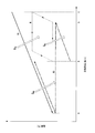
- FIG. 2 is a characteristic diagram showing a mutual heat exchange state in the drain hot water W1, the boiler feed water W2, and the heat medium M in relation to the exchange heat quantity (horizontal axis) and the temperature (vertical axis).
- the solid line indicates the heat exchange state of the drain hot water W1
- the alternate long and short dash line indicates the heat exchange state of the boiler supply water W2
- the broken line indicates the heat exchange state of the heat medium M.
- the BD region on the horizontal axis shows the heat exchange process between the boiler feed water W2 and the gaseous heat medium M in the second heat exchanger r2, and the total amount of heat QBD is the heat in the gaseous state. It moves from the medium M to the boiler feed water W2. That is, in this BD region, the boiler feed water W2 is heated from about 30 ° C. (initial temperature) to nearly 40 ° C., while the gaseous heat medium M is sequentially changed from gas to liquid at a predetermined condensation temperature. To do.
- the DC region on the horizontal axis indicates a heat exchange process in which the gaseous heat medium M is cooled to near the condensation temperature by the turbine r4.
- the B-C region on the horizontal axis shows the heat exchange process between the drain hot water W1 and the liquid heat medium M in the first heat exchanger r1, and the total amount of heat QBC is the liquid heat from the drain hot water W1.
- the AB region on the horizontal axis shows the heat exchange process between the drain hot water W1 and the boiler feed water W2 in the auxiliary heat exchanger H, and the total amount of heat Q AB is changed from the drain hot water W1 to the boiler feed water W2.
- the boiler feed water W2 that has been heated to nearly 40 ° C. by the second heat exchanger r2 is further heated to nearly 65 ° C. by the drain hot water W1, while the first heat exchanger r1
- the drain hot water W1 cooled to 80 to 90 ° C is cooled to close to 50 ° C.
- the Rankine cycle R power is generated by the heat medium M acting dynamically on the turbine r4 as a drive medium, and the generator r5 is rotated by the power of the turbine r4, whereby AC power is generated. P is generated. That is, in the boiler feed water preheating system of the present invention, the Rankine cycle R is provided to generate AC power P in addition to preheating the boiler feed water W2.
- the Rankine cycle R is Naturally, a larger effective energy can be obtained than when the boiler feed water W2 is heated to 65 ° C. (preheated) using only the auxiliary heat exchanger H.
- the Rankine cycle R is configured to heat (heat up) the boiler feed water W2 using the drain hot water W1, but the present invention is not limited to this.
- waste heat generated in the boiler in addition to the drain hot water W1.
- the combustion exhaust gas generated in the combustor is a waste heat source having a higher temperature (several hundred degrees Celsius) than the drain hot water W1, and may be used instead of the boiler feed water W2.
- the Rankine cycle is configured to heat (heat up) the boiler feed water W2 using combustion exhaust gas
- the auxiliary heat exchanger H uses the boiler hot water W1 as in the above embodiment. It is conceivable to heat (heat up) the feed water W2.
- the Rankine cycle R is configured using the heating medium M (low boiling point heating medium) whose boiling point is lower than that of water, but the present invention is not limited to this.
- a heat medium other than the heat medium exemplified as the low boiling point heat medium may be used, and further, a high boiling point heat medium having a boiling point higher than that of water may be used instead of the low boiling point heat medium.
- a high boiling point heating medium can be used because the temperature of the combustion exhaust gas is several hundred degrees C. which is considerably higher than the boiling point of water.
- a plurality of Rankine cycles are provided from the upstream side to the downstream side of the combustion exhaust gas and boiler feed water W2, and a high boiling point heat medium is used in the upstream side, that is, the Rankine cycle in which the temperature of the combustion exhaust gas is relatively high.
- a low boiling point heating medium can be used.
- Rankine cycle efficiency is defined as 1- (TC / TH), where the maximum temperature of the heating medium M is “TH” and the condensation temperature of the heating medium M is “TC”. The higher the is, the better the cycle efficiency.
- the auxiliary heat exchanger H that preheats the boiler feed water W2 is provided, but the present invention is not limited to this. You may delete the auxiliary heat exchanger H as needed.
- the boiler feed water W2 is the target of heating (preheating), but the present invention is not limited to this.
- the combustion air supplied to the boiler combustor may be subject to heating (preheating).
- the drain hot water W1 supplied from the auxiliary heat exchanger H to the waste water treatment device is used as the boiler feed water W2. May be reused as In this case, the entire boiler supply water W2 may be covered with the drain hot water W1, or a part of the boiler supply water W2 may be covered with the drain hot water W1. Thus, by reusing the drain hot water W1 as the boiler supply water W2, the amount of heat retained in the drain hot water W1 can be used effectively. When a part of the boiler feed water W2 is covered with the drain hot water W1, it is desirable that the temperature of the boiler feed water W2 is mixed at the same temperature as the drain hot water W1 during the heating of the boiler feed water W2.
- the present invention provides a boiler feed water preheating system and a boiler feed water preheating method in which the amount of collected effective energy (exergy) is higher than that of the prior art.
Landscapes
- Engineering & Computer Science (AREA)
- Mechanical Engineering (AREA)
- General Engineering & Computer Science (AREA)
- Physics & Mathematics (AREA)
- Thermal Sciences (AREA)
- Water Supply & Treatment (AREA)
- Chemical & Material Sciences (AREA)
- Combustion & Propulsion (AREA)
- Heat-Pump Type And Storage Water Heaters (AREA)
- Engine Equipment That Uses Special Cycles (AREA)
- Air Supply (AREA)
Abstract
Description
本願は、2013年7月26日に、日本に出願された特願2013-155754号に基づき優先権を主張し、その内容をここに援用する。
なお、上記有効エネルギは、エクセルギとも呼ばれる熱力学的な概念であり、ある系から力学的な仕事として取り出せるエネルギとして一般に知られている。本願発明における有効エネルギは、ボイラの熱源が有する総エネルギのうち力学的な仕事(電気等の動力)として回収できるエネルギ(仕事量)を意味する。
(1)上記実施形態では、ドレン温水W1を用いてボイラ供給水W2を加熱(昇温)するようにランキンサイクルRを構成したが、本発明はこれに限定されない。ボイラで発生する廃熱には、ドレン温水W1の他に様々なものがある。例えば燃焼器で発生する燃焼排ガスは、ドレン温水W1よりも高温(数百℃)な廃熱源であり、ボイラ供給水W2に代えて用いることが考えられる。
r1 第1熱交換器
r2 第2熱交換器
r3 ポンプ
r4 タービン
r5 発電機
H 補助熱交換器
W1 ドレン温水
W2 ボイラ供給水
M 熱媒(低沸点熱媒)
Claims (7)
- ボイラに供給される水(ボイラ供給水)を所定の予熱手段で予熱するボイラ用給水予熱システムであって、
前記予熱手段は、所定の熱媒を用いることにより、前記ボイラにおける廃熱源の熱を前記ボイラ供給水に移動させて予熱すると共に電力を発生させる熱サイクルであるボイラ用給水予熱システム。 - 前記予熱手段は、前記熱サイクルに加えて、前記廃熱源と前記ボイラ供給水とを熱交換させて前記ボイラ供給水を予熱する補助熱交換器を備える請求項1に記載のボイラ用給水予熱システム。
- 前記廃熱源は、前記ボイラが発生した水蒸気を所定用途に使用して得られるドレン温水である請求項1または2に記載のボイラ用給水予熱システム。
- 前記熱媒は、沸点が水よりも低い低沸点熱媒である請求項3に記載のボイラ用給水予熱システム。
- 前記廃熱源は、前記ボイラの燃焼器で発生した燃焼排ガスである請求項1または2に記載のボイラ用給水予熱システム。
- 前記熱媒は、沸点が水よりも高い高沸点熱媒である請求項5に記載のボイラ用給水予熱システム。
- ボイラに供給される水(ボイラ供給水)を予熱するボイラ用給水予熱方法であって、
所定の熱サイクルを用いることにより、前記ボイラにおける廃熱源の熱を前記ボイラ供給水に移動させて予熱すると共に電力を発生させるボイラ用給水予熱方法。
Priority Applications (5)
| Application Number | Priority Date | Filing Date | Title |
|---|---|---|---|
| SG11201600425QA SG11201600425QA (en) | 2013-07-26 | 2014-07-24 | Boiler water supply preheater system and boiler water supply preheating method |
| CN201480040723.2A CN105408591B (zh) | 2013-07-26 | 2014-07-24 | 锅炉用给水预热系统以及锅炉用给水预热方法 |
| DE112014003454.1T DE112014003454B4 (de) | 2013-07-26 | 2014-07-24 | Vorheiz-System einer Kesselwasser-Zufuhr |
| MYPI2016700197A MY183364A (en) | 2013-07-26 | 2014-07-24 | Boiler water supply preheater system and boiler water supply preheating method |
| US15/000,333 US9857074B2 (en) | 2013-07-26 | 2016-01-19 | Boiler water supply preheater system and boiler water supply preheating method |
Applications Claiming Priority (2)
| Application Number | Priority Date | Filing Date | Title |
|---|---|---|---|
| JP2013155754A JP2015025422A (ja) | 2013-07-26 | 2013-07-26 | ボイラ用給水予熱システム及びボイラ用給水予熱方法 |
| JP2013-155754 | 2013-07-26 |
Related Child Applications (1)
| Application Number | Title | Priority Date | Filing Date |
|---|---|---|---|
| US15/000,333 Continuation US9857074B2 (en) | 2013-07-26 | 2016-01-19 | Boiler water supply preheater system and boiler water supply preheating method |
Publications (1)
| Publication Number | Publication Date |
|---|---|
| WO2015012345A1 true WO2015012345A1 (ja) | 2015-01-29 |
Family
ID=52393379
Family Applications (1)
| Application Number | Title | Priority Date | Filing Date |
|---|---|---|---|
| PCT/JP2014/069541 Ceased WO2015012345A1 (ja) | 2013-07-26 | 2014-07-24 | ボイラ用給水予熱システム及びボイラ用給水予熱方法 |
Country Status (7)
| Country | Link |
|---|---|
| US (1) | US9857074B2 (ja) |
| JP (1) | JP2015025422A (ja) |
| CN (1) | CN105408591B (ja) |
| DE (1) | DE112014003454B4 (ja) |
| MY (1) | MY183364A (ja) |
| SG (1) | SG11201600425QA (ja) |
| WO (1) | WO2015012345A1 (ja) |
Families Citing this family (1)
| Publication number | Priority date | Publication date | Assignee | Title |
|---|---|---|---|---|
| JP2015025422A (ja) | 2013-07-26 | 2015-02-05 | 株式会社Ihi | ボイラ用給水予熱システム及びボイラ用給水予熱方法 |
Citations (7)
| Publication number | Priority date | Publication date | Assignee | Title |
|---|---|---|---|---|
| JPS6487811A (en) * | 1987-09-30 | 1989-03-31 | Hitachi Ltd | Heat and electricity supply plant |
| JPH06241006A (ja) * | 1993-02-18 | 1994-08-30 | Toshiba Corp | 複合発電設備 |
| JPH1030407A (ja) * | 1996-07-18 | 1998-02-03 | Toshiba Corp | コンバインドサイクル発電プラント |
| JP2000045713A (ja) * | 1998-07-27 | 2000-02-15 | Toshiba Corp | コンバインドサイクル発電プラント |
| JP2011214451A (ja) * | 2010-03-31 | 2011-10-27 | Jfe Engineering Corp | 太陽熱利用廃棄物発電装置 |
| JP2012198018A (ja) * | 2010-02-19 | 2012-10-18 | Ihi Corp | 排熱回収システム、エネルギ供給システム及び排熱回収方法 |
| JP2013011272A (ja) * | 2011-06-03 | 2013-01-17 | Toda Kogyo Corp | 発電システム |
Family Cites Families (12)
| Publication number | Priority date | Publication date | Assignee | Title |
|---|---|---|---|---|
| DE4335216C2 (de) * | 1993-05-10 | 2003-04-24 | Saar En Gmbh | Dampfkraftanlage zur Erzeugung elektrischer Energie |
| JPH0893412A (ja) | 1994-09-27 | 1996-04-09 | Mitsui Eng & Shipbuild Co Ltd | 排熱回収ボイラ |
| US6230480B1 (en) * | 1998-08-31 | 2001-05-15 | Rollins, Iii William Scott | High power density combined cycle power plant |
| JP2003336504A (ja) | 2002-05-17 | 2003-11-28 | Ebara Corp | 発電装置 |
| GB201006497D0 (en) * | 2010-04-19 | 2010-06-02 | Dow Corning | Solar thermal power plant |
| US9091182B2 (en) * | 2010-12-20 | 2015-07-28 | Invensys Systems, Inc. | Feedwater heater control system for improved rankine cycle power plant efficiency |
| US9316122B2 (en) * | 2010-12-20 | 2016-04-19 | Invensys Systems, Inc. | Feedwater heater control system for improved Rankine cycle power plant efficiency |
| KR101434908B1 (ko) * | 2013-05-23 | 2014-08-29 | 포스코에너지 주식회사 | 중저온 폐열을 활용한 난방 열원 또는 전기 생산 시스템, 및 그 제어방법 |
| US9617874B2 (en) * | 2013-06-17 | 2017-04-11 | General Electric Technology Gmbh | Steam power plant turbine and control method for operating at low load |
| JP2015025422A (ja) | 2013-07-26 | 2015-02-05 | 株式会社Ihi | ボイラ用給水予熱システム及びボイラ用給水予熱方法 |
| JP6432768B2 (ja) * | 2013-11-01 | 2018-12-05 | パナソニックIpマネジメント株式会社 | 排熱回収装置、加熱システム、蒸気ボイラー及び脱臭システム |
| US20150369084A1 (en) * | 2014-06-24 | 2015-12-24 | Joel M. Levin | System for preheating boiler feedwater and cooling condenser water |
-
2013
- 2013-07-26 JP JP2013155754A patent/JP2015025422A/ja active Pending
-
2014
- 2014-07-24 SG SG11201600425QA patent/SG11201600425QA/en unknown
- 2014-07-24 WO PCT/JP2014/069541 patent/WO2015012345A1/ja not_active Ceased
- 2014-07-24 MY MYPI2016700197A patent/MY183364A/en unknown
- 2014-07-24 DE DE112014003454.1T patent/DE112014003454B4/de not_active Expired - Fee Related
- 2014-07-24 CN CN201480040723.2A patent/CN105408591B/zh not_active Expired - Fee Related
-
2016
- 2016-01-19 US US15/000,333 patent/US9857074B2/en not_active Expired - Fee Related
Patent Citations (7)
| Publication number | Priority date | Publication date | Assignee | Title |
|---|---|---|---|---|
| JPS6487811A (en) * | 1987-09-30 | 1989-03-31 | Hitachi Ltd | Heat and electricity supply plant |
| JPH06241006A (ja) * | 1993-02-18 | 1994-08-30 | Toshiba Corp | 複合発電設備 |
| JPH1030407A (ja) * | 1996-07-18 | 1998-02-03 | Toshiba Corp | コンバインドサイクル発電プラント |
| JP2000045713A (ja) * | 1998-07-27 | 2000-02-15 | Toshiba Corp | コンバインドサイクル発電プラント |
| JP2012198018A (ja) * | 2010-02-19 | 2012-10-18 | Ihi Corp | 排熱回収システム、エネルギ供給システム及び排熱回収方法 |
| JP2011214451A (ja) * | 2010-03-31 | 2011-10-27 | Jfe Engineering Corp | 太陽熱利用廃棄物発電装置 |
| JP2013011272A (ja) * | 2011-06-03 | 2013-01-17 | Toda Kogyo Corp | 発電システム |
Also Published As
| Publication number | Publication date |
|---|---|
| DE112014003454T5 (de) | 2016-05-04 |
| CN105408591A (zh) | 2016-03-16 |
| US20160138797A1 (en) | 2016-05-19 |
| JP2015025422A (ja) | 2015-02-05 |
| SG11201600425QA (en) | 2016-02-26 |
| DE112014003454B4 (de) | 2020-06-18 |
| CN105408591B (zh) | 2017-09-29 |
| MY183364A (en) | 2021-02-18 |
| US9857074B2 (en) | 2018-01-02 |
Similar Documents
| Publication | Publication Date | Title |
|---|---|---|
| JP7173245B2 (ja) | 発電システム | |
| CN103089341B (zh) | 发电设备 | |
| RU2529767C2 (ru) | Способ для генерации пара с высоким кпд | |
| CN102792021B (zh) | 利用由使用太阳能产生的蒸汽和/或热水发电的装置和方法 | |
| US20100263380A1 (en) | Cascaded organic rankine cycle (orc) system using waste heat from a reciprocating engine | |
| RU2570131C2 (ru) | Способ работы тепловой электрической станции | |
| CN102084093A (zh) | 用于使热动力循环运行的方法以及热动力循环 | |
| US20170363002A1 (en) | Co2 power generation system | |
| CN105387729B (zh) | 物料冷却余热发电系统 | |
| JP4738222B2 (ja) | 動力システム | |
| JP7290520B2 (ja) | Orc発電システム | |
| CN104975897A (zh) | 基于导热油冷却燃气内燃机缸壁回收烟气余热的发电系统 | |
| WO2015012345A1 (ja) | ボイラ用給水予熱システム及びボイラ用給水予熱方法 | |
| JP2004020140A (ja) | 空気加熱装置及び火力発電設備 | |
| KR20170141515A (ko) | 직접 연소 타입의 초임계 이산화탄소 발전 시스템 | |
| RU2560622C1 (ru) | Способ утилизации низкопотенциальной теплоты системы маслоснабжения подшипников паровой турбины тепловой электрической станции | |
| JP2017504761A (ja) | 発電機からの廃熱を利用した熱発電プラント | |
| JP6776190B2 (ja) | 熱エネルギー回収装置及び熱エネルギー回収方法 | |
| JP2011106475A (ja) | 動力システム | |
| RU2560624C1 (ru) | Способ утилизации теплоты тепловой электрической станции | |
| RU2560615C1 (ru) | Способ работы тепловой электрической станции | |
| JP2014177922A (ja) | バイナリー発電システム | |
| RU2560621C1 (ru) | Способ работы тепловой электрической станции | |
| RU2560611C1 (ru) | Способ работы тепловой электрической станции | |
| JP6057219B2 (ja) | バイナリー発電システム |
Legal Events
| Date | Code | Title | Description |
|---|---|---|---|
| WWE | Wipo information: entry into national phase |
Ref document number: 201480040723.2 Country of ref document: CN |
|
| 121 | Ep: the epo has been informed by wipo that ep was designated in this application |
Ref document number: 14828942 Country of ref document: EP Kind code of ref document: A1 |
|
| WWE | Wipo information: entry into national phase |
Ref document number: 112014003454 Country of ref document: DE |
|
| WWE | Wipo information: entry into national phase |
Ref document number: IDP00201601019 Country of ref document: ID |
|
| 122 | Ep: pct application non-entry in european phase |
Ref document number: 14828942 Country of ref document: EP Kind code of ref document: A1 |