WO2015012263A1 - 炭素数3以下の飽和炭化水素の吸着方法、分離方法、及び分離装置 - Google Patents
炭素数3以下の飽和炭化水素の吸着方法、分離方法、及び分離装置 Download PDFInfo
- Publication number
- WO2015012263A1 WO2015012263A1 PCT/JP2014/069315 JP2014069315W WO2015012263A1 WO 2015012263 A1 WO2015012263 A1 WO 2015012263A1 JP 2014069315 W JP2014069315 W JP 2014069315W WO 2015012263 A1 WO2015012263 A1 WO 2015012263A1
- Authority
- WO
- WIPO (PCT)
- Prior art keywords
- metal complex
- saturated hydrocarbon
- ligand
- group
- adsorption
- Prior art date
- Legal status (The legal status is an assumption and is not a legal conclusion. Google has not performed a legal analysis and makes no representation as to the accuracy of the status listed.)
- Ceased
Links
Images


Classifications
-
- C—CHEMISTRY; METALLURGY
- C07—ORGANIC CHEMISTRY
- C07C—ACYCLIC OR CARBOCYCLIC COMPOUNDS
- C07C7/00—Purification; Separation; Use of additives
- C07C7/12—Purification; Separation; Use of additives by adsorption, i.e. purification or separation of hydrocarbons with the aid of solids, e.g. with ion-exchangers
-
- B—PERFORMING OPERATIONS; TRANSPORTING
- B01—PHYSICAL OR CHEMICAL PROCESSES OR APPARATUS IN GENERAL
- B01D—SEPARATION
- B01D53/00—Separation of gases or vapours; Recovering vapours of volatile solvents from gases; Chemical or biological purification of waste gases, e.g. engine exhaust gases, smoke, fumes, flue gases, aerosols
- B01D53/02—Separation of gases or vapours; Recovering vapours of volatile solvents from gases; Chemical or biological purification of waste gases, e.g. engine exhaust gases, smoke, fumes, flue gases, aerosols by adsorption, e.g. preparative gas chromatography
-
- B—PERFORMING OPERATIONS; TRANSPORTING
- B01—PHYSICAL OR CHEMICAL PROCESSES OR APPARATUS IN GENERAL
- B01J—CHEMICAL OR PHYSICAL PROCESSES, e.g. CATALYSIS OR COLLOID CHEMISTRY; THEIR RELEVANT APPARATUS
- B01J20/00—Solid sorbent compositions or filter aid compositions; Sorbents for chromatography; Processes for preparing, regenerating or reactivating thereof
- B01J20/22—Solid sorbent compositions or filter aid compositions; Sorbents for chromatography; Processes for preparing, regenerating or reactivating thereof comprising organic material
- B01J20/223—Solid sorbent compositions or filter aid compositions; Sorbents for chromatography; Processes for preparing, regenerating or reactivating thereof comprising organic material containing metals, e.g. organo-metallic compounds, coordination complexes
- B01J20/226—Coordination polymers, e.g. metal-organic frameworks [MOF], zeolitic imidazolate frameworks [ZIF]
-
- B—PERFORMING OPERATIONS; TRANSPORTING
- B01—PHYSICAL OR CHEMICAL PROCESSES OR APPARATUS IN GENERAL
- B01J—CHEMICAL OR PHYSICAL PROCESSES, e.g. CATALYSIS OR COLLOID CHEMISTRY; THEIR RELEVANT APPARATUS
- B01J20/00—Solid sorbent compositions or filter aid compositions; Sorbents for chromatography; Processes for preparing, regenerating or reactivating thereof
- B01J20/30—Processes for preparing, regenerating, or reactivating
- B01J20/34—Regenerating or reactivating
- B01J20/3491—Regenerating or reactivating by pressure treatment
-
- C—CHEMISTRY; METALLURGY
- C07—ORGANIC CHEMISTRY
- C07D—HETEROCYCLIC COMPOUNDS
- C07D487/00—Heterocyclic compounds containing nitrogen atoms as the only ring hetero atoms in the condensed system, not provided for by groups C07D451/00 - C07D477/00
- C07D487/02—Heterocyclic compounds containing nitrogen atoms as the only ring hetero atoms in the condensed system, not provided for by groups C07D451/00 - C07D477/00 in which the condensed system contains two hetero rings
- C07D487/08—Bridged systems
-
- C—CHEMISTRY; METALLURGY
- C07—ORGANIC CHEMISTRY
- C07D—HETEROCYCLIC COMPOUNDS
- C07D487/00—Heterocyclic compounds containing nitrogen atoms as the only ring hetero atoms in the condensed system, not provided for by groups C07D451/00 - C07D477/00
- C07D487/12—Heterocyclic compounds containing nitrogen atoms as the only ring hetero atoms in the condensed system, not provided for by groups C07D451/00 - C07D477/00 in which the condensed system contains three hetero rings
- C07D487/18—Bridged systems
-
- B—PERFORMING OPERATIONS; TRANSPORTING
- B01—PHYSICAL OR CHEMICAL PROCESSES OR APPARATUS IN GENERAL
- B01D—SEPARATION
- B01D2253/00—Adsorbents used in seperation treatment of gases and vapours
- B01D2253/10—Inorganic adsorbents
- B01D2253/112—Metals or metal compounds not provided for in B01D2253/104 or B01D2253/106
- B01D2253/1122—Metals
-
- B—PERFORMING OPERATIONS; TRANSPORTING
- B01—PHYSICAL OR CHEMICAL PROCESSES OR APPARATUS IN GENERAL
- B01D—SEPARATION
- B01D2253/00—Adsorbents used in seperation treatment of gases and vapours
- B01D2253/20—Organic adsorbents
-
- B—PERFORMING OPERATIONS; TRANSPORTING
- B01—PHYSICAL OR CHEMICAL PROCESSES OR APPARATUS IN GENERAL
- B01D—SEPARATION
- B01D2257/00—Components to be removed
- B01D2257/70—Organic compounds not provided for in groups B01D2257/00 - B01D2257/602
- B01D2257/702—Hydrocarbons
- B01D2257/7022—Aliphatic hydrocarbons
Definitions
- the present invention relates to a selective adsorption method for saturated hydrocarbons having 3 or less carbon atoms, a separation method using the same, and a separation apparatus for performing the separation method.
- a method using activated carbon or zeolite generally known as an adsorbent is known, but saturated hydrocarbons, particularly saturated hydrocarbons having 3 or less carbon atoms are used. It is difficult to adsorb highly selectively, and no practical adsorption method capable of adsorbing such saturated hydrocarbons with high selectivity has been provided.
- Non-patent Document 1 Japanese Patent Application Laidiol et al. , J. Am. Chem. Soc. 2010, 132, p. In 17704-17706 (Non-patent Document 1), it has been found that, in a specific porous metal complex, the affinity for a saturated hydrocarbon is higher than the affinity for an unsaturated hydrocarbon.
- a practically excessively low pressure for example, less than 1 kPa at 25 ° C.
- 8832-8840 (Non-patent Document 2) describes a relatively high pressure as a pressure for recovering propane, there is a problem that in this case, it is necessary to excessively raise the temperature.
- the present invention has been made in view of the above-described problems of the prior art, and selectively selects saturated hydrocarbons in a mixture even if they are hydrocarbons having 3 or less carbon atoms such as propylene and propane. Gas adsorbed in a temperature and pressure range (for example, 1 kPa or more at 25 ° C.) that can be used without requiring an excessive temperature rise or an excessively low pressure in practice. It is an object of the present invention to provide a saturated hydrocarbon adsorption method, a separation method using the same, and a separation apparatus for performing the separation method.
- the saturated hydrocarbon adsorption method of the present invention has the following formula (1):
- P is a saturated hydrocarbon group which may have a substituent other than R a ;
- R a is a functional group having a coordination property to a metal ion;
- m is an integer of 2 or more, a plurality of R a may be the same or different from each other.
- first ligand represented by the formula (hereinafter also referred to as “first ligand”) and a metal ion, a saturated hydrocarbon having 3 or less carbon atoms, an unsaturated hydrocarbon
- P of the first ligand may be substituted with a saturated hydrocarbon group having 1 to 8 carbon atoms, and has 3 to 12 carbon atoms having a cyclic structure.
- the saturated hydrocarbon group is preferable.
- R a of the first ligand is “—CO 2 ⁇ ”, “—CS 2 ⁇ ”, “—C ( ⁇ O) S ⁇ ”.
- the metal ions are preferably ions of at least one metal selected from the group consisting of chromium, manganese, iron, cobalt, nickel, copper, and zinc. .
- the metal complex further includes a second ligand that satisfies the condition that it is a “heterocyclic compound containing 2 to 4 heteroatoms”. It is preferable to include. Furthermore, the second ligand is more preferably a heterocyclic compound containing 2 or more and 4 or less heteroatoms and no double bond.
- the metal complex is represented by the following formula (2):
- Q is an R a substituent other than may have an unsaturated hydrocarbon group; R a and m R a and each of the first in the ligand independently It is synonymous with m.
- the 3rd ligand represented by these is further included.
- the molar ratio represented by [first ligand]: [third ligand] is 100: 0 to 5:95. It is preferable that it is the range of these.
- the metal complex is represented by the following formula (3):
- a first ligand A represented by: A second ligand B which is a heterocyclic compound containing 2 to 4 heteroatoms and no double bond; Following formula (4):
- Q 1 is a halogen atom or an unsaturated hydrocarbon group having 12 or less carbon atoms which may be substituted by a saturated hydrocarbon group having 1 to 8 carbon atoms; m 1 is 1 to 2; Is an integer.
- the hydrocarbon separation method of the present invention is a hydrocarbon separation method including a step of separating the saturated hydrocarbon and the unsaturated hydrocarbon using the saturated hydrocarbon adsorption method of the present invention.
- a desorption step of changing the pressure to a second predetermined pressure and desorbing the saturated hydrocarbon adsorbed on the metal complex is included.
- the separation apparatus of the present invention comprises a separation means comprising a metal complex containing a ligand represented by the above formula (1) and a metal ion, An introduction means for introducing a mixture containing a saturated hydrocarbon having 3 or less carbon atoms and an unsaturated hydrocarbon into the separation means,
- the hydrocarbon separation apparatus separates the saturated hydrocarbon from the unsaturated hydrocarbon by selectively adsorbing the saturated hydrocarbon to the metal complex by bringing the mixture into contact with the metal complex.
- “selectively adsorbing saturated hydrocarbons to a metal complex” means saturation when saturated hydrocarbons and unsaturated hydrocarbons are adsorbed to metal complexes under the same temperature and pressure conditions. It means that the amount of adsorption of hydrocarbons is greater than the amount of adsorption of unsaturated hydrocarbons.
- the amount of adsorption can be measured by a volumetric method using, for example, an automatic specific surface area / pore distribution measuring apparatus (BELSORP-miniII manufactured by Nippon Bell Co., Ltd.), and the temperature (adsorption temperature) condition at that time is as follows: It is preferably 173 to 373 K, and the pressure (adsorption pressure) condition is preferably 3 kPa to 3 MPa.
- the unsaturated hydrocarbon at that time preferably has the same carbon number as that of the saturated hydrocarbon.
- saturated hydrocarbons in a mixture can be selectively adsorbed even if they are hydrocarbons having 3 or less carbon atoms such as propylene and propane, and practically.
- Saturated hydrocarbon adsorption method capable of recovering gas (hydrocarbon) adsorbed in a temperature and pressure range (for example, 1 kPa or more at 25 ° C.) that can be used without requiring excessive temperature rise or excessive pressure reduction It is possible to provide a separation method using the same, and a separation apparatus for performing the separation method.
- FIG. 4 is a graph showing a powder X-ray diffraction pattern of the metal complex obtained in Synthesis Example 1.
- 5 is a graph showing a powder X-ray diffraction pattern of the metal complex obtained in Synthesis Example 2.
- 6 is a graph showing a powder X-ray diffraction pattern of the metal complex obtained in Synthesis Example 3.
- 6 is a graph showing a powder X-ray diffraction pattern of the metal complex obtained in Synthesis Example 4.
- 6 is a graph showing a powder X-ray diffraction pattern of the metal complex obtained in Synthesis Example 5.
- 10 is a graph showing a powder X-ray diffraction pattern of the metal complex obtained in Synthesis Example 6.
- 10 is a graph showing a powder X-ray diffraction pattern of the metal complex obtained in Synthesis Example 7.
- 10 is a graph showing a powder X-ray diffraction pattern of the metal complex obtained in Synthesis Example 8.
- 10 is a graph showing a powder X-ray diffraction pattern of the metal complex obtained in Synthesis Example 9.
- 6 is a graph showing a powder X-ray diffraction pattern of the metal complex obtained in Comparative Synthesis Example 1. It is a graph which shows the adsorption / desorption isotherm of propane and propylene measured in Example 1 using the metal complex obtained in Synthesis Example 1.
- FIG. 6 is a graph showing adsorption / desorption isotherms of propane and propylene measured in Example 7 using the metal complex obtained in Synthesis Example 7.
- FIG. It is a graph which shows the adsorption / desorption isotherm of propane and propylene measured in Example 8 using the metal complex obtained in Synthesis Example 8.
- 10 is a graph showing a powder X-ray diffraction pattern of the metal complex obtained in Synthesis Example 10.
- Example 10 is a graph showing a powder X-ray diffraction pattern of the metal complex obtained in Synthesis Example 11. It is a graph which shows the adsorption-and-desorption isotherm of the propane and propylene which were measured in Example 10 using the metal complex obtained in the synthesis example 10. It is a graph which shows the adsorption / desorption isotherm of propane and propylene measured in Example 11 using the metal complex obtained in Synthesis Example 11. It is a graph which shows the breakthrough curve of the mixed gas of the propane, propylene, and nitrogen which were measured in Example 12 using the metal complex obtained by the synthesis example 3.
- a saturated hydrocarbon having 3 or less carbon atoms and a non-carbon having 3 or less carbon atoms are added to the metal complex containing the ligand represented by the formula (1) and a metal ion.
- the saturated hydrocarbon is brought into contact with a mixture containing a saturated hydrocarbon (in this specification, it may be referred to as “a mixture containing a saturated hydrocarbon having 3 or less carbon atoms and an unsaturated hydrocarbon”).
- a method for adsorbing saturated hydrocarbons that is selectively adsorbed on the metal complex is selectively adsorbed on the metal complex.
- a plurality of things “may be the same as or different from each other” means that a plurality of things “may be the same or all may be different, Only may be the same ".
- P in the first ligand is a group formed by removing m hydrogen atoms from a saturated hydrocarbon compound that may have a substituent other than Ra , and is an acyclic hydrocarbon group. Alternatively, it may be a cyclic hydrocarbon group.
- P in such a first ligand is preferably a saturated hydrocarbon group having 12 or less carbon atoms which may be substituted with a halogen atom or a saturated hydrocarbon group having 1 to 8 carbon atoms. Further, it is more preferably a saturated hydrocarbon group having 3 to 12 carbon atoms having a cyclic structure, which may be substituted by a saturated hydrocarbon group having 1 to 8 carbon atoms, and a saturated hydrocarbon having 1 to 3 carbon atoms. It is more preferably a saturated hydrocarbon group having 5 to 10 carbon atoms having a cyclic structure which may be substituted with a group.
- saturated hydrocarbon compound in which m hydrogen atoms are removed to form P include methane, ethane, propane, butane, pentane, hexane, heptane, octane, nonane, decane, cyclopropane, cyclobutane, and cyclopentane.
- the metal complex obtained can be expected to have a relatively higher affinity for saturated hydrocarbons
- heptane, octane, cyclopentane, cyclohexane, cycloheptane, decalin, [2.2.2] -bicyclo Octane and adamantane are preferred, cyclohexane, decalin, [2.2.2] -bicyclooctane and adamantane are more preferred, and cyclohexane and adamantane are even more preferred.
- R a of the first ligand may be a functional group having a coordination property to a metal ion, and includes “—CO 2 ⁇ ”, “—CS 2 ⁇ ”, “—C ( ⁇ O) S ⁇ . , “—C ( ⁇ O) N (R A ) ⁇ ”, “—SO 3 ⁇ ”, “—PO 4 (R A ) ⁇ ”, “—C ⁇ N”, “—S ⁇ ”, “— Examples thereof include a group represented by any one selected from the group consisting of “O ⁇ ”, “—N (R A ) ⁇ ”, “pyridyl group” and “imidazole group”.
- M of the first ligand may be an integer of 1 to 4, but a low-dimensional metal complex (the description of the low-dimensional metal complex will be described later) can be easily obtained. Since expression can be expected, it is preferably an integer of 1 to 2, more preferably 1. When m is an integer of 2 or more, a plurality of Ra may be the same or different from each other.
- P of the first ligand may have a substituent other than Ra , and when the number of substituents is 2 or more, these substituents are the same as each other. May be different.
- substituent other than R a include a halogen atom and a saturated hydrocarbon group having 1 to 8 carbon atoms which may be substituted with a halogen atom.
- Such a saturated hydrocarbon group is preferably a saturated hydrocarbon group having 1 to 6 carbon atoms which may be substituted with a halogen atom, and more preferably one having 1 to 3 carbon atoms which may be substituted with a halogen atom.
- halogen atom examples include a fluorine atom, a chlorine atom, a bromine atom, and an iodine atom. Among them, a fluorine atom and a chlorine atom are preferable, and a fluorine atom is more preferable.
- a substituent other than the R a is, which may be linear or branched or cyclic, cyclic In some cases, it may be monocyclic or polycyclic.
- the saturated hydrocarbon group having 1 to 6 carbon atoms includes a methyl group, an ethyl group, an n-propyl group, an isopropyl group, an n-butyl group, an isobutyl group, and a sec-butyl group.
- Isopropyl group, n-butyl group, isobutyl group, n-pentyl group, n-hexyl group, cyclopropyl group, cyclobutyl group, cyclopentyl group, cyclohexyl group are preferred, methyl group, ethyl group, n-propyl group, isopropyl group Group, cyclopentyl group, and cyclohexyl group are more preferable, methyl group, ethyl group, n-propyl group, and isopropyl group are more preferable, and methyl group is particularly preferable.
- one of the first ligands may be contained alone or in combination of two or more, and in the case of containing in combination of two or more, the first P of one ligand is a saturated hydrocarbon group having 3 to 10 carbon atoms having a cyclic structure (PI) and a saturated hydrocarbon group having a cyclic structure having more carbon atoms than PI and having 12 or less carbon atoms ( More preferred is a combination with PII).
- the molar ratio represented by [PI]: [PII] is more preferably 25:75 to 99: 1, particularly preferably 50:50 to 98: 2, and 75:25 to 95: 5 is particularly preferred.
- the metal ion contained in the metal complex may be an ion of an arbitrary metal element, but is preferably an ion of a metal element selected from Groups 2 to 13 of the periodic table.
- metal complexes As such metal ions, the synthesis of metal complexes is relatively easy, so magnesium, aluminum, calcium, scandium, titanium, vanadium, chromium, manganese, iron, cobalt, nickel, copper, zinc, strontium, yttrium. More preferred is an ion of at least one metal selected from the group consisting of niobium, molybdenum, ruthenium, rhodium, cadmium, barium, lanthanum, tantalum and tungsten. As said metal complex, 1 type in the said metal ion may be included independently, or 2 or more types may be included in combination.
- metal ions since the metal salt as a raw material is relatively inexpensive, the group consisting of magnesium, aluminum, calcium, titanium, vanadium, chromium, manganese, iron, cobalt, nickel, copper, and zinc At least one metal ion selected from is more preferable, and since the synthesis of the metal complex is relatively easy, at least one selected from the group consisting of chromium, manganese, iron, cobalt, nickel, copper and zinc Metal ions are particularly preferred. Furthermore, as such a metal ion, since the synthesis of a metal complex is very easy, a copper or zinc ion is particularly preferred, and a copper ion is particularly preferred.
- the metal ions are usually 1 to 7 valent cations.
- the cation is preferably divalent to hexavalent, more preferably divalent to tetravalent, and even more preferably divalent to trivalent since it is necessary to form a metal complex with a plurality of ligands. And particularly preferably divalent.
- the metal complex used in the present invention includes “a heteroatom having 2 to 4 atoms (for example, at least one atom selected from the group consisting of N, O and S). It is preferable to further include a second ligand that is a heterocyclic compound containing, and it is preferable that the second ligand does not include a double bond.
- the second ligand may be a monocyclic group, a condensed ring group, or a group in which monocyclic groups are linked.
- triethylenediamine that is, 1, 4-diazabicyclo [2.2.2] octane
- piperazine 2,5-dimethylpiperazine, 3,3′-bipiperidine, 4,4′-bipiperidine, 1,3-di- (4-piperidyl) propane, hexa
- Examples include methylenetetramine, 1,4-dioxane, and 1,4-dithiane. One of these may be used alone, or two or more may be used in combination.
- Such a second ligand is at least one compound selected from the group consisting of triethylenediamine, piperazine, 4,4′-bipiperidine and hexamethylenetetramine because the stability of the metal complex is further increased. It is preferable that triethylenediamine, hexamethylenetetramine or piperazine is more preferable, and triethylenediamine is more preferable.
- the metal complex used in the present invention may further include a third ligand represented by the formula (2) in addition to the first ligand.
- the absolute difference between the number of carbon atoms in the P structure of the first ligand and the number of carbon atoms in the Q structure of the third ligand is preferably an integer of 0 to 6, more preferably an integer of 0 to 4, and further preferably an integer of 0 to 2.
- Q of the third ligand is a group formed by removing m hydrogen atoms from an unsaturated hydrocarbon compound which may have a substituent other than Ra , and is an acyclic hydrocarbon group. Or a cyclic hydrocarbon group.
- Q of such a third ligand is preferably an unsaturated hydrocarbon group having 12 or less carbon atoms, which may be substituted by a halogen atom or a saturated hydrocarbon group having 1 to 8 carbon atoms. .
- a C 3-12 unsaturated hydrocarbon group having a cyclic structure which may be substituted by a halogen atom or a C 1-8 saturated hydrocarbon group, and a fluorine atom or a carbon number
- an unsaturated hydrocarbon group having 5 to 10 carbon atoms having a cyclic structure which may be substituted by 1 to 3 saturated hydrocarbon groups.
- the unsaturated hydrocarbon compound in which m hydrogen atoms are removed to form Q include butene, pentene, hexene, heptene, octene, cyclopropene, cyclobutene, cyclopentene, cyclohexene, cycloheptene, cyclooctene, and cyclopentadiene.
- 1,2,3,4-tetrahydronaphthalene benzene, naphthalene, anthracene, etc., preferably cyclopentene, cyclohexene, cycloheptene, cyclopentadiene, benzene, naphthalene, more preferably cyclohexene, benzene, naphthalene. More preferably, it is benzene.
- Q of the third ligand may have a substituent other than Ra , and preferred examples thereof include a halogen atom (more preferably a fluorine atom) or P of the first ligand. Are the same as those of the preferred examples of the substituent other than Ra .
- 1 type in the said 3rd ligand may be included independently, or 2 or more types may be included in combination.
- the selectivity of saturated hydrocarbons during hydrocarbon adsorption is further improved, or a more suitable pressure is adsorbed. Since it can be applied to gas recovery, it is preferable that the following relationships are satisfied.
- the molar ratio represented by [metal ion]: [first ligand] is 1.0: 0.
- the range is preferably 5 to 1.0: 4.0, more preferably 1.0: 0.8 to 1.0: 3.0, and 1.0: 1.0 to 1 More preferably, it is in the range of 0.0: 2.0.
- the said metal complex further contains the said 3rd ligand in addition to the said 1st ligand, about the said metal ion, the said 1st ligand, and the said 3rd ligand, [
- the molar ratio represented by [metal ion]: [first ligand + third ligand] is preferably in the range of 1.0: 0.5 to 1.0: 4.0, The range is more preferably 1.0: 0.8 to 1.0: 3.0, and still more preferably 1.0: 1.0 to 1.0: 2.0.
- the ratio of the third ligand in the metal complex is such that the molar ratio represented by [first ligand]: [third ligand] is in the range of 100: 0 to 5:95. Preferably, it is in the range of 100: 0 to 20:80, more preferably in the range of 100: 0 to 50:50. Further, considering that selective adsorption characteristics of saturated hydrocarbons are further increased, the molar ratio represented by [first ligand]: [third ligand] is 85:15 to 50:50. Is particularly preferably in the range of 80:20 to 50:50, and particularly preferably in the range of 80:20 to 60:40.
- the metal complex further contains the second ligand in addition to the first ligand, the metal ion and the second ligand contained in the metal complex ]:
- the molar ratio represented by [second ligand] is preferably in the range of 1.0: 0.2 to 1.0: 3.0, and 1.0: 0.3 to 1 More preferably, it is in the range of 0.0: 2.0, and more preferably in the range of 1.0: 0.5 to 1.0: 1.0.
- the selectivity of saturated hydrocarbons at the time of hydrocarbon adsorption can be further improved, or more suitable pressure can be applied to recovering the adsorbed gas, so that the metal complex has ionic bonds and coordination.
- It is preferably a metal complex that forms an integrated structure having one-dimensional (linear) or two-dimensional (planar) dimensionality by being connected by a bond, and forms a one-dimensional integrated structure. More preferred is a metal complex.
- a one-dimensional integrated structure is such that the metal complex has a divalent metal ion, the first ligand having one functional group coordinated to the metal ion, and a heteroatom.
- such a one-dimensional integrated structure has a structure in which the metal complex includes a divalent metal ion, the first ligand having one functional group coordinated to the metal ion, and a heterogeneous structure.
- auxiliary ligands other than said 1st ligand, said 2nd ligand, and said 3rd ligand.
- auxiliary ligands include triethylamine, water, N, N-dimethylformamide, N, N-diethylformamide, N, N-dimethylacetamide, N-methyl-2-pyrrolidone, dimethyl sulfoxide, acetone, Examples include pyridine, tetrahydrofuran, diethyl ether, dimethoxyethane, and methyl ethyl ether, and water, N, N-dimethylformamide, and N, N-diethylformamide are preferable.
- These auxiliary ligands may be one kind or two or more kinds.
- the metal complex used in the present invention preferably has a regular structure and a flexible structure because the separation efficiency between unsaturated hydrocarbons and saturated hydrocarbons can be further increased.
- the regular structure here means that at least one peak derived from the unit cell is observed at 15 ° (2 ⁇ ) or less, preferably 12 ° or less, more preferably 10 ° or less by measurement of powder X-ray diffraction.
- the ordered structure is characterized, and the peak is preferably 3 ° (2 ⁇ ) or more, more preferably 4 ° or more.
- the flexible structure here is characterized in that the structure is changed by an external stimulus (for example, adsorption of guest molecules).
- the powder X-ray diffraction pattern of the metal complex having a flexible structure changes with the adsorption of small molecules.
- the metal complex having a flexible structure changes its structure again when the adsorbed small molecules are desorbed, and usually recovers the structure before adsorbing the small molecules.
- the metal complex includes a first ligand A represented by the formula (3), A second ligand B which is a heterocyclic compound containing 2 to 4 heteroatoms and no double bond; A third ligand C represented by the formula (4); Ions of at least one metal selected from the group consisting of chromium, manganese, iron, cobalt, nickel, copper and zinc; It is preferable that it is a metal complex containing.
- P 1 of the ligand A is a saturated hydrocarbon having 12 or less carbon atoms which may be substituted with a halogen atom or a saturated hydrocarbon group having 1 to 8 carbon atoms in the P of the first ligand.
- a group formed by removing m hydrogen atoms from a compound, and a preferable example is as described in the first ligand.
- m 1 of the ligand A is an integer of 1 to 2 out of m of the first ligand, and a low-dimensional compound is easily obtained and better selective adsorption characteristics are exhibited. , Preferably 1.
- the metal ion contained in the metal complex is an ion of at least one metal selected from the group consisting of chromium, manganese, iron, cobalt, nickel, copper and zinc among the above metal ions.
- a metal ion since the synthesis of a metal complex is very easy, a copper or zinc ion is particularly preferred, and a copper ion is particularly preferred.
- the preferable example of the said ligand B is synonymous with the preferable example of said 2nd ligand.
- Q 1 of the ligand C is an unsaturated carbon atom having 12 or less carbon atoms which may be substituted with a halogen atom or a saturated hydrocarbon group having 1 to 8 carbon atoms in the Q of the third ligand.
- a group obtained by removing m hydrogen atoms from a hydrogen compound, and a preferable example is as described in the third ligand.
- the method for producing the metal complex used in the present invention is not particularly limited, but the ligand or a precursor thereof (the precursor of the first ligand and the second ligand as necessary).
- a ligand and / or a precursor of a third ligand) are reacted in a solvent with a metal salt comprising the metal ion (and, if necessary, a counter ion and crystal water) or a hydrate thereof. It is preferable to manufacture by.
- solvents such as water, methanol, ethanol, 2-propanol, tetrahydrofuran, acetone, acetonitrile, N, N-dimethylacetamide, N, N-diethylacetamide, chloroform and the like can be used. May further add another auxiliary ligand.
- the functional groups in the precursor of the first ligand and the precursor of the third ligand include “—CO 2 A”, “—CS 2 A”, “—C ( ⁇ O)”. “SA”, “—C ( ⁇ O) N (R A ) A”, “—SO 2 A”, “—PO 4 (R A ) A”, “—C ⁇ N”, “—SA”, “— Examples are groups represented by any one selected from the group consisting of “OA” and “—N (R A ) A”.
- A is a hydrogen atom, an alkali metal atom or an ammonium ion which may be substituted with an alkyl group, preferably a hydrogen atom.
- the molar ratio of the precursor of the first ligand, the second ligand, the precursor of the third ligand, and the metal salt to be reacted is the same as that of each metal salt. It is necessary to adjust according to the coordination ability of the ligand.
- the preferred ratio of the precursor of the first ligand and the precursor of the third ligand to be reacted is the ratio of the first ligand contained in the metal complex to be produced to the above-mentioned It is also necessary to adjust based on the ratio with the third ligand. Further, the yield of the ligand or the precursor thereof to be reacted may be improved by making the ligand or the precursor thereof in excess of the stoichiometric ratio compared to the metal salt. In some cases, the amount of ligand used excessively can be reduced by carrying out the reaction at a high concentration.
- the metal salt is preferably fluoride, chloride, bromide, nitrate, sulfate, perchlorate, acetate, tetrafluoroborate, tetraphenylborate, hexafluorophosphate, hexafluorosilicic acid. Salts, hydrates thereof, or combinations thereof. Nitrate, sulfate, perchlorate, acetate, tetrafluoroborate are preferred because they are highly available and the coordinating power of the counter anion is preferably low enough not to interfere with the intended reaction. , Hexafluorophosphates or hydrates thereof, more preferably nitrates, sulfates, acetates or hydrates thereof.
- the reaction temperature at the time of reacting the ligand or the precursor thereof with the metal salt is preferably 0 ° C. or higher and 200 ° C. or lower, more preferably 10 ° C. or higher and 150 ° C. or lower, further preferably 10 ° C. or higher and 100 ° C. or lower, 20 degreeC or more and 60 degrees C or less are especially preferable.
- the reaction is preferably carried out under a pressure of 0.01 to 10 MPa, more preferably carried out under a pressure of 0.05 to 1 MPa, further preferably carried out under a pressure of 0.08 to 0.12 MPa. Usually, it is performed under normal pressure.
- the reaction time is usually 1 minute to 1 week, preferably 5 minutes to 120 hours.
- reaction vessel used for such a reaction an open vessel or a closed vessel such as an autoclave can be used.
- the reaction vessel can be heated by using a liquid or gaseous heat medium, or by irradiating microwaves or ultrasonic waves.
- the generated metal complex is precipitated in the reaction solution as a precipitate.
- the precipitated metal complex can be washed with the same type of solvent used for the reaction or a solvent that is more volatile than the solvent used for the reaction. preferable.
- the obtained metal complex is porous, since the solvent may be adsorbed in the pores, it is preferable to dry the metal complex in order to remove these. As such drying, vacuum drying under room temperature or heating conditions is preferable.
- the precursor of the first ligand (and the precursor of the third ligand as necessary) and the metal salt It is also possible to adopt a stepwise synthesis method in which an intermediate is synthesized in advance, and then the second ligand is added to the intermediate to obtain the metal complex.
- the saturated hydrocarbon is selectively brought into contact with the metal complex by contacting the metal complex with a mixture containing a saturated hydrocarbon having 3 or less carbon atoms and an unsaturated hydrocarbon. Adsorbed.
- metal complexes may be one kind or may contain two or more kinds.
- the saturated hydrocarbon is ethane, propane, or cyclopropane, and ethane or propane is preferable.
- unsaturated hydrocarbons include ethylene, propylene, cyclopropene, and acetylene, with ethylene and propylene being preferred.
- the saturated hydrocarbon and saturated hydrocarbon to be brought into contact with the metal complex are a mixture containing a saturated hydrocarbon having 3 or less carbon atoms and an unsaturated hydrocarbon, and the mixture is preferably a gas.
- carbon number of saturated hydrocarbon and unsaturated hydrocarbon is the same, or there are many carbon numbers of saturated hydrocarbon. Specific examples include a mixture of ethane and ethylene, a mixture of propane and ethylene, and a mixture of propane and propylene, more preferably a mixture of propane and propylene.
- the hydrocarbon separation method of the present invention is a hydrocarbon separation method including a step of separating the saturated hydrocarbon and the unsaturated hydrocarbon using the saturated hydrocarbon adsorption method of the present invention.
- the saturated hydrocarbon or unsaturated hydrocarbon obtained by separation by the separation method of the present invention may have a composition ratio different from that of the mixture before the separation, but either one of the separated obtained products is 80 mol% or more. It is preferably 90 mol% or more, more preferably 95% or more, and particularly preferably 98% or more.
- the metal complex can be used as it is or in a powder form by appropriate pulverization, but it may be molded by an appropriate molding means and used as a molded body.
- the type of molding agent and the type of the molding agent are selected so that the hydrocarbon gas adsorption characteristics and the hydrocarbon gas desorption characteristics after adsorption are not significantly impaired. It is preferable to determine the amount used.
- An example of such a molding means is press molding.
- the shape of the molded body when used as an adsorbent is desirably a shape that can maintain the strength required for the adsorbent.
- rate is improved, it is preferable that the surface area of a molded article is large.
- specific processes for separating the unsaturated hydrocarbon and the saturated hydrocarbon using the metal complex described above include, for example, a pressure swing adsorption method (pressure swing adsorption method) and a temperature swing adsorption.
- Method temperature fluctuation adsorption method: Temperature Swing Adsorption
- permeation separation method membrane separation
- the metal complex is brought into contact with a mixture of the unsaturated hydrocarbon and the saturated hydrocarbon under a first predetermined pressure (adsorption pressure), and the saturated hydrocarbon is selected as the metal complex.
- adsorption pressure a first predetermined pressure
- the saturated hydrocarbon is selected as the metal complex.
- the pressure in the space where the metal complex is arranged (for example, in the adsorption tank) is raised or reduced to a desired adsorption pressure in advance, and then the mixture is subjected to the adsorption pressure under the adsorption pressure.
- saturated hydrocarbons are adsorbed and concentrated on the metal complex with high selectivity, and the hydrocarbon depletion and unsaturated hydrocarbons are discharged from the space.
- the pressure is changed to a second predetermined pressure (desorption pressure) to desorb hydrocarbons adsorbed on the metal complex. More preferably, the method further includes a step.
- a desorption process regeneration process
- the pressure in the space where the metal complex that selectively adsorbs one of the hydrocarbons is reduced to a desired desorption pressure, and is adsorbed by the metal complex.
- the saturated hydrocarbon concentrate is discharged from the space by desorbing from the metal complex.
- the unsaturated hydrocarbons in the space may be replaced with saturated hydrocarbons by feeding a small amount of saturated hydrocarbons before changing the pressure to the second predetermined pressure (desorption pressure).
- the purity of the obtained saturated hydrocarbon or unsaturated hydrocarbon is low, and a device for obtaining the higher purity saturated hydrocarbon or unsaturated hydrocarbon is necessary.
- the adsorption step and the desorption step are repeated twice or more.
- the adsorption conditions in the pressure swing adsorption method are determined depending on the object to be separated and the metal complex used, and the adsorption temperature is preferably 173 to 373K, more preferably 223 to 353K. More preferably, it is 253 to 353K, and more preferably 273 to 333K.
- the adsorption pressure varies depending on the working temperature and the metal complex used, but is preferably 3 kPa to 3 MPa, more preferably 10 kPa to 2 MPa. More preferably, it is 30 kPa to 2 MPa, and particularly preferably 100 kPa to 2 MPa.
- the adsorption pressure is a pressure at which the difference between the adsorption amount of one hydrocarbon and the adsorption amount of the other hydrocarbon is increased, preferably 2 times or more, more preferably 5 times or more, and still more preferably. A pressure of 10 times or more is employed.
- the desorption pressure a pressure at which the saturated hydrocarbon adsorption amount is 50% or less of the saturated adsorption amount is employed, preferably 20% or less, more preferably 10% or less, and even more preferably 5%. The following pressure is employed.
- the desorption conditions of the adsorbed components in the pressure swing adsorption method are determined by the separation object and the metal complex used.
- the desorption pressure varies depending on the object to be separated, the operating temperature, and the metal complex to be used. However, if the gas recovery pressure is too low, a recompression load is required for storage or use of the gas. It is preferable to recover by pressure.
- Such pressure is preferably 2 kPa or more, and more preferably 5 kPa or more. More preferably, it is 10 kPa to 2 MPa, and particularly preferably 20 kPa to 1.5 MPa. According to the method for adsorbing saturated hydrocarbons of the present invention, the gas adsorbed in the pressure region that can be used without requiring excessive pressure reduction in practice can be recovered.
- the desorption temperature is preferably 223 to 373K. Although it is not always necessary to positively increase the temperature in the desorption step, it is preferable to compensate for the latent heat necessary for desorption, and it may be preferable to perform temperature control and heat retention.
- Such a separation apparatus includes separation means including the metal complex described above, and introduction means for introducing a mixture containing a saturated hydrocarbon having 3 or less carbon atoms and an unsaturated hydrocarbon into the separation means, An apparatus for separating the saturated hydrocarbon and the unsaturated hydrocarbon by selectively adsorbing the saturated hydrocarbon to the metal complex by bringing the mixture into contact with the metal complex.
- the hydrocarbon separation apparatus preferably further comprises pressure control means for controlling the pressure of the space in which the metal complex is disposed in the separation means, and the pressure control means provides a first predetermined pressure. It is preferable that the adsorbing step described above can be performed by bringing the mixture into contact with the metal complex and selectively adsorbing one of the hydrocarbons to the metal complex.
- the pressure is changed to the second predetermined pressure by the pressure control means, and the saturated hydrocarbon adsorbed on the metal complex is removed. It is preferable that the above-described desorption step can be performed by separating them.
- FIG. 1 shows a preferred embodiment of this hydrocarbon separation apparatus.
- an adsorption tank (separation means) 1 filled with the above-described metal complex is disposed, and an inlet pipe P1 having a valve V1 at one end thereof is disposed.
- the compressor 2 (introducing means) is connected, and the compressor 2 is connected to a feed gas P2 having a valve V2 (the mixture) and a purge gas introducing pipe P3 having a valve V3.
- a decompressor 3 pressure control means
- a product gas having a valve V5 is connected to the decompressor 3.
- Hydrogen) discharge pipe P5 and purge gas discharge pipe P6 having valve V6 are connected.
- a control means 4 for example, PLC
- the compressor 2 the decompressor 3
- the valves V1 to V6 so that their operations can be controlled.
- the separation apparatus of the present invention further includes a temperature control means capable of controlling the temperature.
- the following control is performed. That is, first, purge gas is introduced into the adsorption tank 1 by the compressor 2, and then the pressure in the adsorption tank 1 is reduced by the decompressor 3 so as to become the first predetermined pressure (adsorption pressure). Next, the raw material gas is introduced into the adsorption tank 1 by the compressor 2 under the pressure, and the saturated hydrocarbon is selectively adsorbed and concentrated on the metal complex, and the hydrocarbon depletion and unsaturated hydrocarbon are concentrated. Is discharged as the first product gas.
- the pressure in the adsorption tank 1 is reduced to the second predetermined pressure (desorption pressure) by the decompressor 3 so that the saturated hydrocarbon concentrate adsorbed on the metal complex is desorbed from the metal complex. Separated and discharged as a second product gas.
- the present invention is not limited to the above-described embodiment.
- one of the compressor and the decompressor serves as both the introduction unit and the pressure control unit, Either one may be sufficient.
- adsorption tank filled with the metal complex a plurality of adsorption tanks (adsorption towers) may be connected in parallel or in series.
- Measurement of adsorption / desorption isotherm Measurement was performed by a volumetric method using an automatic specific surface area / pore distribution measuring device. At this time, the sample was dried at 373 K and 5 Pa for 16 hours prior to measurement to remove adsorbed water and the like. Details of the measurement conditions are shown below. ⁇ Measurement conditions> Apparatus: BELSORP-miniII manufactured by Nippon Bell Co., Ltd. Pressure program: 5 kPa or less ⁇ 120 kPa ⁇ 10 kPa or less Equilibrium waiting time: 300 seconds.
- [Cu 2 (chc) 4 ], [Cu 2 (bza) 4 ], [Cu 2 (adc) 4 (H 2 O) 2 ], [Cu 2 (Fbza) 4 ] and the like used in the following synthesis examples [Cu 2 (F5bza) 4 ] is the following document: J. et al. Chem. Soc. 1965, p. 6466-6477 According to the method described in 1. Structural formulas of [Cu 2 (chc) 4 ], [Cu 2 (bza) 4 ], [Cu 2 (Fbza) 4 ], and [Cu 2 (F5bza) 4 ] are shown below.
- Solution B was added to Solution A, and the mixture was stirred at 298 K for 10 minutes, 0.056 g (0.5 mmol) of 1,4-diazabicyclo [2.2.2] octane was added, and the mixture was stirred at 298 K for 24 hours.
- the deposited metal complex was collected by suction filtration, washed with chloroform, and further dried at 298 K and 5 Pa for 2 hours to obtain 0.3129 g (yield 83%) of the desired metal complex.
- the powder X-ray diffraction pattern of the obtained metal complex is shown in FIG. From the results shown in FIG. 3, it was confirmed that the obtained metal complex had an ordered structure.
- Solution B was added to Solution A, and the mixture was stirred at 298 K for 10 minutes, 0.056 g (0.5 mmol) of 1,4-diazabicyclo [2.2.2] octane was added, and the mixture was stirred at 298 K for 24 hours.
- the precipitated metal complex was collected by suction filtration, washed with chloroform, and further dried at 298 K and 5 Pa for 2 hours to obtain 0.2913 g (yield 78%) of the target metal complex.
- the powder X-ray diffraction pattern of the obtained metal complex is shown in FIG. From the results shown in FIG. 4, it was confirmed that the obtained metal complex had an ordered structure.
- FIG. 5 shows a powder X-ray diffraction pattern of the obtained metal complex. From the results shown in FIG. 5, it was confirmed that the obtained metal complex had an ordered structure.
- Solution B was added to Solution A, and the mixture was stirred at 298 K for 10 minutes, 0.056 g (0.5 mmol) of 1,4-diazabicyclo [2.2.2] octane was added, and the mixture was stirred at 298 K for 24 hours.
- the deposited metal complex was collected by suction filtration, washed with chloroform, and further dried at 298 K and 5 Pa for 2 hours to obtain 0.1933 g (yield 53%) of the desired metal complex.
- the powder X-ray diffraction pattern of the obtained metal complex is shown in FIG. From the results shown in FIG. 6, it was confirmed that the obtained metal complex had an ordered structure.
- FIG. 7 shows a powder X-ray diffraction pattern of the obtained metal complex. From the results shown in FIG. 7, it was confirmed that the obtained metal complex had an ordered structure.
- Solution B was added to Solution A, and the mixture was stirred at 298 K for 10 minutes, 0.046 g (0.413 mmol) of 1,4-diazabicyclo [2.2.2] octane was added, and the mixture was stirred at 298 K for 24 hours.
- the precipitated metal complex was collected by suction filtration, washed with chloroform, and further dried at 298 K and 5 Pa for 2 hours to obtain 0.2259 g (yield 70%) of the target metal complex.
- the powder X-ray diffraction pattern of the obtained metal complex is shown in FIG. From the results shown in FIG. 8, it was confirmed that the obtained metal complex had an ordered structure.
- Solution B was added to Solution A, and the mixture was stirred at 298 K for 10 minutes, 0.045 g (0.4 mmol) of 1,4-diazabicyclo [2.2.2] octane was added, and the mixture was stirred at 298 K for 24 hours.
- the precipitated metal complex was collected by suction filtration, washed with chloroform, and further dried at 298 K and 5 Pa for 2 hours to obtain 0.2632 g (yield 85%) of the target metal complex.
- the powder X-ray diffraction pattern of the obtained metal complex is shown in FIG. From the results shown in FIG. 9, it was confirmed that the obtained metal complex had an ordered structure.
- Solution B was added to Solution A, and the mixture was stirred at 298 K for 10 minutes, 0.045 g (0.4 mmol) of 1,4-diazabicyclo [2.2.2] octane was added, and the mixture was stirred at 298 K for 24 hours.
- the precipitated metal complex was collected by suction filtration, washed with chloroform, and further dried at 298 K and 5 Pa for 2 hours to obtain 0.2425 g (yield 79%) of the target metal complex.
- the powder X-ray diffraction pattern of the obtained metal complex is shown in FIG. From the results shown in FIG. 10, it was confirmed that the obtained metal complex had an ordered structure.
- Solution B was added to Solution A, and the mixture was stirred at 298 K for 10 minutes, and then 0.14 g (1.0 mmol) of 1,4-diazabicyclo [2.2.2] octane was added and stirred at 298 K for 24 hours.
- the precipitated metal complex was collected by suction filtration, washed with a solution of chloroform: methanol 5: 1, and further dried at 298K and 5 Pa for 2 hours to obtain 0.6391 g (yield 84%) of the target metal complex. Obtained.
- the powder X-ray diffraction pattern of the obtained metal complex is shown in FIG. From the results shown in FIG. 21, it was confirmed that the obtained metal complex had an ordered structure.
- the precipitated metal complex was collected by suction filtration, washed with dehydrated acetone, and further dried at 298 K and 5 Pa for 2 hours to obtain 0.350 g (yield 86%) of the desired metal complex.
- the powder X-ray diffraction pattern of the obtained metal complex is shown in FIG. From the results shown in FIG. 22, it was confirmed that the obtained metal complex had an ordered structure.
- Example 1 For the metal complex obtained in Synthesis Example 1, the adsorption and desorption isotherms of propane and propylene at 298 K were measured by the capacitance method. The results are shown in FIG. 12. In the range of 200 to 400 kPa, the propane adsorption amount exceeded the propylene adsorption amount, and the value of propane adsorption amount / propylene adsorption amount was about 3 times at the maximum. It was confirmed that there is sex. Moreover, it was confirmed that the adsorbed propane can be recovered at the pressure by reducing the pressure to 70 kPa.
- Example 2 For the metal complex obtained in Synthesis Example 2, the adsorption and desorption isotherms of propane and propylene at 273 K were measured by the capacitance method. The results are shown in FIG. 13. In the range of 40 to 90 kPa, the propane adsorption amount exceeded the propylene adsorption amount, and the value of propane adsorption amount / propylene adsorption amount was about 4 times at the maximum. It was confirmed that there is sex. Moreover, it was confirmed that the adsorbed propane can be recovered at the pressure by reducing the pressure to 17 kPa.
- Example 3 For the metal complex obtained in Synthesis Example 3, the adsorption and desorption isotherms of propane and propylene at 273 K and 303 K were measured by the capacitance method, respectively. The results are shown in FIGS. In the measurement at 273 K, the propane adsorption amount exceeded the propylene adsorption amount in the range of 20 to 30 kPa. In the measurement at 303K, the propane adsorption amount exceeded the propylene adsorption amount in the range of 80 to 120 kPa, and the value of propane adsorption amount / propylene adsorption amount was about 25 times at maximum. It was confirmed that there is. Moreover, it was confirmed that the adsorbed propane can be recovered at the pressure by reducing the pressure to 13 kPa.
- Example 4 When the adsorption and desorption isotherms of propane and propylene at 298K were measured by the volumetric method for the metal complex obtained in Synthesis Example 4, the propane adsorption amount exceeded the propylene adsorption amount in a certain pressure range, and the adsorption property was selective. It is confirmed that there is. Moreover, it is confirmed that the adsorbed propane can be recovered at 1 kPa or more by reducing the pressure.
- Example 5 When the adsorption and desorption isotherms of propane and propylene at 298K were measured by the volumetric method for the metal complex obtained in Synthesis Example 5, the propane adsorption amount exceeded the propylene adsorption amount in a certain pressure range, and the adsorption property was selective. It is confirmed that there is. Moreover, it is confirmed that the adsorbed propane can be recovered at 1 kPa or more by reducing the pressure.
- Example 6 For the metal complex obtained in Synthesis Example 6, the adsorption and desorption isotherms of propane and propylene at 273 K were measured by the capacitance method. The results are shown in FIG. 16. In the range of 60 to 120 kPa, the propane adsorption amount exceeded the propylene adsorption amount, and the value of propane adsorption amount / propylene adsorption amount was about 4 times at the maximum. It was confirmed that there is sex. Moreover, it was confirmed that the adsorbed propane can be recovered at the pressure by reducing the pressure to 30 kPa.
- Example 7 For the metal complex obtained in Synthesis Example 7, the adsorption and desorption isotherms of propane and propylene at 273 K were measured by the capacitance method. The results are shown in FIG. 17. In the range of 42 to 60 kPa, the propane adsorption amount exceeded the propylene adsorption amount, and the value of propane adsorption amount / propylene adsorption amount was about 20 times at the maximum. It was confirmed that there is sex. Moreover, it was confirmed that the adsorbed propane can be recovered at the pressure by reducing the pressure to 25 kPa.
- Example 8 For the metal complex obtained in Synthesis Example 8, the adsorption and desorption isotherms of propane and propylene at 273 K were measured by the capacitance method. The results are shown in FIG. 18. In the range of 35 to 55 kPa, the propane adsorption amount exceeded the propylene adsorption amount, and the value of propane adsorption amount / propylene adsorption amount was about 23 times at the maximum. It was confirmed that there is sex. Moreover, it was confirmed that the adsorbed propane can be recovered at the pressure by reducing the pressure to 25 kPa.
- Example 9 For the metal complex obtained in Synthesis Example 9, the adsorption and desorption isotherms of propane and propylene at 273 K were measured by the capacitance method. The results are shown in FIG. 19. In the range of 32 to 50 kPa, the propane adsorption amount exceeded the propylene adsorption amount, and the value of propane adsorption amount / propylene adsorption amount was about 35 times at the maximum. It was confirmed that there is sex. Moreover, it was confirmed that the adsorbed propane can be recovered at the pressure by reducing the pressure to 24 kPa.
- Example 10 For the metal complex obtained in Synthesis Example 10, the adsorption and desorption isotherms of propane and propylene at 273 K were measured by the capacitance method. The results are shown in FIG. 23. In the range of 20 to 60 kPa, the propane adsorption amount exceeded the propylene adsorption amount, and the value of propane adsorption amount / propylene adsorption amount was about 28 times at the maximum. It was confirmed that there is sex. Moreover, it was confirmed that the adsorbed propane can be recovered at the pressure by reducing the pressure to 5 kPa.
- Example 11 For the metal complex obtained in Synthesis Example 11, the adsorption and desorption isotherms of propane and propylene at 273 K were measured by the capacitance method. The results are shown in FIG. 24. In the range of 80 to 120 kPa, the propane adsorption amount exceeded the propylene adsorption amount, and the value of the propane adsorption amount / propylene adsorption amount was about 5 times at the maximum. It was confirmed that there is sex. Moreover, it was confirmed that the adsorbed propane can be recovered at the pressure by reducing the pressure to 20 kPa.
- a gas chromatograph detector: TCD, carrier gas: Ar
- a gas chromatograph detector: TCD, carrier gas: Ar
- Comparative Example 1 For the metal complex obtained in Comparative Synthesis Example 1, the adsorption and desorption isotherms of propane and propylene at 273 K were measured by the volumetric method. The results are shown in FIG. 20, and no significant difference was observed in the adsorption characteristics.
- a saturated hydrocarbon (even a minor component) in a mixture is selected even if it is a hydrocarbon having 3 or less carbon atoms such as propylene and propane and having the same carbon number.
- Gas adsorbed in a temperature and pressure region for example, 1 kPa or more at 25 ° C.
- a saturated hydrocarbon adsorption method capable of recovering (hydrogen), a separation method using the same, and a separation apparatus for performing the separation method.
- the present invention is very useful as a technique for reducing the size of an apparatus for separating saturated hydrocarbons having 3 or less carbon atoms and saving energy for separation.
- SYMBOLS 1 Adsorption tank (separation means), 2 ... Compressor (introduction means), 3 ... Decompression machine (pressure control means), 4 ... Control means, V1-V6 ... Valve, P1-P6 ... Piping.
Landscapes
- Chemical & Material Sciences (AREA)
- Organic Chemistry (AREA)
- Analytical Chemistry (AREA)
- Chemical Kinetics & Catalysis (AREA)
- Engineering & Computer Science (AREA)
- Oil, Petroleum & Natural Gas (AREA)
- Inorganic Chemistry (AREA)
- Water Supply & Treatment (AREA)
- General Chemical & Material Sciences (AREA)
- Solid-Sorbent Or Filter-Aiding Compositions (AREA)
- Organic Low-Molecular-Weight Compounds And Preparation Thereof (AREA)
Abstract
下記式(1)で表される配位子と金属イオンとを含む金属錯体に、炭素数が3以下の飽和炭化水素と不飽和炭化水素とを含む混合物を接触せしめることにより前記飽和炭化水素を前記金属錯体に選択的に吸着させる、飽和炭化水素の吸着方法。(式(1)中、PはRa以外の置換基を有していてもよい飽和炭化水素基であり;Raは金属イオンに配位性のある官能基であり;mは1~4の整数であり;mが2以上の整数である場合、複数あるRaは互いに同一であっても異なっていてもよい。)
Description
本発明は、炭素数が3以下の飽和炭化水素の選択的吸着方法、それを利用した分離方法、並びに分離方法を実施する分離装置に関する。
吸着特性の違いを利用した分離方法としては、吸着剤として一般的に知られている活性炭やゼオライトを用いる方法が知られているが、飽和炭化水素、特に炭素数が3以下の飽和炭化水素を高選択的に吸着することは困難であり、このような飽和炭化水素を高選択的に吸着することができる実用的な吸着方法は提供されてこなかった。
近年、新たな吸着剤として多孔性金属錯体が検討されており、例えば、J.Gascon et al., J. Am. Chem. Soc.,2010,132,P.17704-17706(非特許文献1)では、特定の多孔性金属錯体において、飽和炭化水素に対する親和性が不飽和炭化水素に対する親和性に比して高いことが見出されている。しかしながら、このような従来の多孔性金属錯体を吸着剤として用いた場合、吸着されたプロパンを回収して吸着剤を再生するためには、実用上過度の低圧化(例えば、25℃で1kPa未満)を要するという問題があった。他方、例えば、J.Gascon et al., Chem. Eur. J.,2011,17,P.8832-8840(非特許文献2)には、プロパンを回収する圧力として比較的高い圧力が記載されているものの、この場合には過度に昇温する必要があるという問題があった。
J.Gascon et al., J. Am. Chem. Soc.,2010,132,P.17704-17706
J.Gascon et al., Chem. Eur. J.,2011,17,P.8832-8840
本発明は、前記従来技術の有する課題に鑑みてなされたものであり、プロピレンとプロパンなどの炭素数が3以下でかつ同じ炭素数の炭化水素であっても混合物中の飽和炭化水素を選択的に吸着することが可能であり、かつ、実用上過度の昇温又は過度の低圧化を要しないで用いることができる温度及び圧力領域(例えば、25℃で1kPa以上)において吸着した気体(炭化水素)を回収することができる飽和炭化水素の吸着方法、それを利用した分離方法、並びに分離方法を実施する分離装置を提供することを目的とする。
本発明者らは、前記目的を達成すべく鋭意研究を重ねた結果、本発明をなすに至った。
すなわち、本発明の飽和炭化水素の吸着方法は、下記式(1):
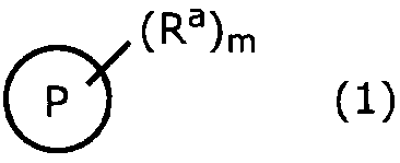
(式(1)中、PはRa以外の置換基を有していてもよい飽和炭化水素基であり;Raは金属イオンに配位性のある官能基であり;mは1~4の整数であり;mが2以上の整数である場合、複数あるRaは互いに同一であっても異なっていてもよい。)
で表される配位子(以下、「第一の配位子」と記すこともある。)と金属イオンとを含む金属錯体に、炭素数が3以下の飽和炭化水素と不飽和炭化水素とを含む混合物を接触せしめることにより前記飽和炭化水素を前記金属錯体に選択的に吸着させる、飽和炭化水素の吸着方法である。
で表される配位子(以下、「第一の配位子」と記すこともある。)と金属イオンとを含む金属錯体に、炭素数が3以下の飽和炭化水素と不飽和炭化水素とを含む混合物を接触せしめることにより前記飽和炭化水素を前記金属錯体に選択的に吸着させる、飽和炭化水素の吸着方法である。
本発明の飽和炭化水素の吸着方法においては、前記第一の配位子のPが、炭素数1~8の飽和炭化水素基によって置換されていてもよい、環状構造を有する炭素数3~12の飽和炭化水素基であることが好ましい。
また、本発明の飽和炭化水素の吸着方法においては、前記第一の配位子のRaが、「-CO2
-」、「-CS2
-」、「-C(=O)S-」及び「-C(=O)NRA-」からなる群から選択されるいずれかで表される基(ここで、RAは水素原子又は炭素数4以下のアルキル基である。)であることが好ましい。
また、本発明の飽和炭化水素の吸着方法においては、前記金属イオンが、クロム、マンガン、鉄、コバルト、ニッケル、銅及び亜鉛からなる群から選択される少なくとも一つの金属のイオンであることが好ましい。
また、本発明の飽和炭化水素の吸着方法においては、前記金属錯体が、「2原子以上4原子以下のヘテロ原子を含む複素環式化合物である」という条件を満たす第二の配位子をさらに含むことが好ましい。さらに、前記第二の配位子としては、2原子以上4原子以下のヘテロ原子を含み、かつ、二重結合を含まない複素環式化合物であることがより好ましい。
また、本発明の飽和炭化水素の吸着方法においては、前記金属錯体が、下記式(2):
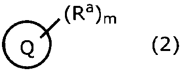
(式(2)中、QはRa以外の置換基を有していてもよい不飽和炭化水素基であり;Ra及びmはそれぞれ独立に前記第一の配位子中のRa及びmと同義である。)
で表される第三の配位子をさらに含むことが好ましい。また、本発明の飽和炭化水素の吸着方法においては、前記金属錯体において、[第一の配位子]:[第三の配位子]で表されるmol比が100:0~5:95の範囲であることが好ましい。
で表される第三の配位子をさらに含むことが好ましい。また、本発明の飽和炭化水素の吸着方法においては、前記金属錯体において、[第一の配位子]:[第三の配位子]で表されるmol比が100:0~5:95の範囲であることが好ましい。
さらに本発明においては、前記金属錯体が、下記式(3):
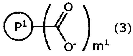
(式(3)中、P1は、ハロゲン原子又は炭素数1~8の飽和炭化水素基によって置換されていてもよい炭素数12以下の飽和炭化水素基であり、m1は1~2の整数である。)
で表される第一の配位子Aと、
2原子以上4原子以下のヘテロ原子を含み、かつ、二重結合を含まない複素環式化合物である第二の配位子Bと、
下記式(4):
で表される第一の配位子Aと、
2原子以上4原子以下のヘテロ原子を含み、かつ、二重結合を含まない複素環式化合物である第二の配位子Bと、
下記式(4):
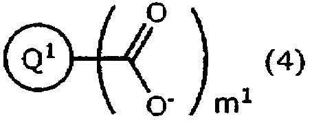
(式(4)中、Q1は、ハロゲン原子又は炭素数1~8の飽和炭化水素基によって置換されていてもよい炭素数12以下の不飽和炭化水素基であり;m1は1~2の整数である。)
で表される第三の配位子Cと、
クロム、マンガン、鉄、コバルト、ニッケル、銅及び亜鉛からなる群から選択される少なくとも一つの金属のイオンと、
を含む金属錯体であることが好ましい。
で表される第三の配位子Cと、
クロム、マンガン、鉄、コバルト、ニッケル、銅及び亜鉛からなる群から選択される少なくとも一つの金属のイオンと、
を含む金属錯体であることが好ましい。
本発明の炭化水素の分離方法は、前記本発明の飽和炭化水素の吸着方法を利用して前記飽和炭化水素と前記不飽和炭化水素とを分離する工程を有する、炭化水素の分離方法である。
このような本発明の炭化水素の分離方法においては、前記金属錯体に、第1の所定圧力の下で前記混合物を接触せしめ、前記飽和炭化水素を前記金属錯体に選択的に吸着させる吸着工程と、前記吸着工程の後に、圧力を第2の所定圧力に変化させ、前記金属錯体に吸着している前記飽和炭化水素を脱離させる脱離工程とを含むことが好ましい。
本発明の分離装置は、上記式(1)で表される配位子と金属イオンとを含む金属錯体を備える分離手段と、
前記分離手段に炭素数が3以下の飽和炭化水素と不飽和炭化水素とを含む混合物を導入する導入手段と
を備えており、
前記金属錯体に、前記混合物を接触せしめることにより前記飽和炭化水素を前記金属錯体に選択的に吸着させ、前記飽和炭化水素と前記不飽和炭化水素とを分離する、炭化水素の分離装置である。
前記分離手段に炭素数が3以下の飽和炭化水素と不飽和炭化水素とを含む混合物を導入する導入手段と
を備えており、
前記金属錯体に、前記混合物を接触せしめることにより前記飽和炭化水素を前記金属錯体に選択的に吸着させ、前記飽和炭化水素と前記不飽和炭化水素とを分離する、炭化水素の分離装置である。
なお、本発明において、「飽和炭化水素を金属錯体に選択的に吸着」するとは、同温、同圧の条件において飽和炭化水素及び不飽和炭化水素をそれぞれ金属錯体に吸着させた場合に、飽和炭化水素の吸着量が不飽和炭化水素の吸着量よりも多くなることをいう。前記吸着量は、例えば、自動比表面積/細孔分布測定装置(日本ベル株式会社製BELSORP-miniII)を用いて容量法により測定することができ、その際の温度(吸着温度)条件としては、173~373Kであることが好ましく、圧力(吸着圧力)条件としては、3kPa~3MPaであることが好ましい。また、その際の前記不飽和炭化水素としては、前記飽和炭化水素の炭素数と同じ炭素数であることが好ましい。
本発明によれば、プロピレンとプロパンなどの炭素数が3以下でかつ同じ炭素数の炭化水素であっても混合物中の飽和炭化水素を選択的に吸着することが可能であり、かつ、実用上過度の昇温又は過度の低圧化を要しないで用いることができる温度及び圧力領域(例えば、25℃で1kPa以上)において吸着した気体(炭化水素)を回収することができる飽和炭化水素の吸着方法、それを利用した分離方法、並びに分離方法を実施する分離装置を提供することが可能となる。
以下、本発明をその好適な実施形態に即して詳細に説明する。先ず、本発明の飽和炭化水素の吸着方法について説明する。
本発明の飽和炭化水素の吸着方法は、前記式(1)で表される配位子と金属イオンとを含む金属錯体に、炭素数が3以下の飽和炭化水素と炭素数が3以下の不飽和炭化水素とを含む混合物(本明細書において、「炭素数が3以下の飽和炭化水素と不飽和炭化水素とを含む混合物」と記すこともある。)を接触せしめることにより前記飽和炭化水素を前記金属錯体に選択的に吸着させる、飽和炭化水素の吸着方法である。
なお、本明細書において、複数あるものが「互いに同一であっても異なっていてもよい」とは、複数あるものが「すべて同一であってもよいし、すべて異なっていてもよく、一部のみが同一であってもよい」ことを意味する。
前記第一の配位子のPは、Ra以外の置換基を有していてもよい飽和炭化水素化合物からm個の水素原子を除いてなる基であり、非環式炭化水素基であっても環式炭化水素基であってもよい。このような第一の配位子のPとしては、ハロゲン原子又は炭素数1~8の飽和炭化水素基によって置換されていてもよい、炭素数12以下の飽和炭化水素基であることが好ましい。また、炭素数1~8の飽和炭化水素基によって置換されていてもよい、環状構造を有する炭素数3~12の飽和炭化水素基であることがより好ましく、炭素数1~3の飽和炭化水素基によって置換されていてもよい、環状構造を有する炭素数5~10の飽和炭化水素基であることがさらに好ましい。
前記m個の水素原子が除かれてPとなる飽和炭化水素化合物の具体例としては、メタン、エタン、プロパン、ブタン、ペンタン、ヘキサン、ヘプタン、オクタン、ノナン、デカン、シクロプロパン、シクロブタン、シクロペンタン、シクロヘキサン、シクロヘプタン、シクロオクタン、デカリン、[2.2.2]-ビシクロオクタン、キュバン、アダマンタンなどが挙げられる。中でも、得られる金属錯体が飽和炭化水素に対して相対的により高い親和性を示すことが期待できることから、ヘプタン、オクタン、シクロペンタン、シクロヘキサン、シクロヘプタン、デカリン、[2.2.2]-ビシクロオクタン、アダマンタンが好ましく、シクロヘキサン、デカリン、[2.2.2]-ビシクロオクタン、アダマンタンがより好ましく、シクロヘキサン、アダマンタンがさらに好ましい。
前記第一の配位子のRaは、金属イオンに配位性のある官能基であればよく、「-CO2
-」、「-CS2
-」、「-C(=O)S-」、「-C(=O)N(RA)-」、「-SO3
-」、「-PO4(RA)-」、「-C≡N」、「-S-」、「-O-」、「-N(RA)-」、「ピリジル基」及び「イミダゾール基」からなる群から選択されるいずれかで表される基が例示される。中でも、得られる金属錯体が秩序だった構造を形成しやすいことから、「-CO2
-」、「-CS2
-」、「-C(=O)S-」及び「-C(=O)N(RA)-」からなる群から選択されるいずれかで表される基が好ましく、「-CO2
-」又は「-C(=O)N(RA)-」で表される基がより好ましく、「-CO2
-」で表される基が特に好ましい。ここで、RAは、水素原子又は炭素数4以下のアルキル基である。
前記第一の配位子のmは、1~4の整数であればよいが、低次元の金属錯体(低次元の金属錯体の説明は後述)が得られやすくより良好な選択的吸着特性の発現が期待できることから、好ましくは1~2の整数であり、より好ましくは1である。なお、mが2以上の整数である場合には、複数あるRaは互いに同一であっても異なっていてもよい。
前記第一の配位子のPは、前記Ra以外の置換基を有していてもよく、該置換基の数が2以上である場合には、これら置換基は、互いに同一であっても異なっていてもよい。前記Ra以外の置換基としては、ハロゲン原子、ハロゲン原子で置換されていてもよい炭素数1~8の飽和炭化水素基が挙げられる。このような飽和炭化水素基として好ましくはハロゲン原子で置換されていてもよい炭素数1~6の飽和炭化水素基であり、より好ましくはハロゲン原子で置換されていてもよい炭素数1~3の飽和炭化水素基であり、さらに好ましくは置換されていない炭素数1~3の飽和炭化水素基である。前記ハロゲン原子としては、フッ素原子、塩素原子、臭素原子、ヨウ素原子が挙げられ、中でもフッ素原子、塩素原子が好ましく、フッ素原子がより好ましい。
前記Ra以外の置換基がハロゲン原子で置換されていてもよい飽和炭化水素基である場合、前記Ra以外の置換基は、直鎖状、分岐鎖状又は環状のいずれでもよく、環状である場合、単環式又は多環式のいずれでもよい。前記Ra以外の置換基のうち、前記炭素数1~6の飽和炭化水素基としては、メチル基、エチル基、n-プロピル基、イソプロピル基、n-ブチル基、イソブチル基、sec-ブチル基、tert-ブチル基、n-ペンチル基、イソペンチル基、ネオペンチル基、tert-ペンチル基、1-メチルブチル基、n-へキシル基、2-メチルペンチル基、3-メチルペンチル基、2,2-ジメチルブチル基、2,3-ジメチルブチル基、シクロプロピル基、シクロブチル基、シクロペンチル基、シクロヘキシル基が挙げられる。
前記PがRa以外の置換基を有する場合、前記第一の配位子の前駆体の合成がより容易となるので、前記Ra以外の置換基はメチル基、エチル基、n-プロピル基、イソプロピル基、n-ブチル基、イソブチル基、n-ペンチル基、n-へキシル基、シクロプロピル基、シクロブチル基、シクロペンチル基、シクロヘキシル基が好ましく、メチル基、エチル基、n-プロピル基、イソプロピル基、シクロペンチル基、シクロヘキシル基がより好ましく、メチル基、エチル基、n-プロピル基、イソプロピル基がさらに好ましく、メチル基が特に好ましい。
前記金属錯体としては、前記第1の配位子のうちの1種を単独で含んでいても2種以上を組み合わせて含んでいてもよく、2種以上を組み合わせて含む場合には、前記第一の配位子のPが、環状構造を有する炭素数3~10の飽和炭化水素基(PI)と環状構造を有する炭素数がPIの炭素数よりも多くかつ12以下の飽和炭化水素基(PII)との組み合わせであることがより好ましい。また、[PI]:[PII]で表されるmol比が25:75~99:1であることがさらに好ましく、50:50~98:2であることが特に好ましく、75:25~95:5であることがとりわけ好ましい。
前記金属錯体に含まれる金属イオンは、任意の金属元素のイオンでよいが、好ましくは周期表第2族から第13族から選ばれる金属元素のイオンである。
このような金属イオンとしては、金属錯体の合成が比較的容易であることから、マグネシウム、アルミニウム、カルシウム、スカンジウム、チタン、バナジウム、クロム、マンガン、鉄、コバルト、ニッケル、銅、亜鉛、ストロンチウム、イットリウム、ニオブ、モリブデン、ルテニウム、ロジウム、カドミウム、バリウム、ランタン、タンタル及びタングステンからなる群から選択される少なくとも一つの金属のイオンがより好ましい。前記金属錯体としては、前記金属イオンのうちの1種を単独で含んでいても2種以上を組み合わせて含んでいてもよい。
また、このような金属イオンとしては、原料となる金属塩が比較的安価であることから、マグネシウム、アルミニウム、カルシウム、チタン、バナジウム、クロム、マンガン、鉄、コバルト、ニッケル、銅及び亜鉛からなる群から選択される少なくとも一つの金属のイオンがさらに好ましく、金属錯体の合成が比較的容易であることから、クロム、マンガン、鉄、コバルト、ニッケル、銅及び亜鉛からなる群から選択される少なくとも一つの金属のイオンが特に好ましい。さらに、このような金属イオンとしては、金属錯体の合成がきわめて容易であることから、銅又は亜鉛のイオンが殊更好ましく、銅のイオンがとりわけ好ましい。
前記金属イオンは、通常、1~7価の陽イオンである。そして、この陽イオンは、複数の配位子と共に金属錯体を形成する必要があることから、好ましくは2~6価であり、より好ましくは2~4価であり、さらに好ましくは2~3価であり、特に好ましくは2価である。
本発明で用いる前記金属錯体は、前記第一の配位子に加えて、「2原子以上4原子以下のヘテロ原子(例えば、N、O及びSからなる群より選ばれる少なくとも1種類の原子)を含む複素環式化合物である」第二の配位子をさらに含むことが好ましく、前記第二の配位子としては、二重結合を含まないことが好ましい。
前記第二の配位子は、単環基であっても縮環基であっても、単環基が連結された基であってもよく、具体例としては、トリエチレンジアミン(すなわち、1,4-ジアザビシクロ[2.2.2]オクタン)、ピペラジン、2,5-ジメチルピペラジン、3,3’-ビピペリジン、4,4’-ビピペリジン、1,3-ジ-(4-ピペリジル)プロパン、ヘキサメチレンテトラミン、1,4-ジオキサン、1,4-ジチアンが挙げられ、これらのうちの1種を単独で用いても2種以上を組み合わせて用いてもよい。このような第二の配位子としては、金属錯体の安定性がより高まるので、トリエチレンジアミン、ピペラジン、4,4’-ビピペリジン及びヘキサメチレンテトラミンからなる群から選択される少なくとも一つの化合物であることが好ましく、トリエチレンジアミン、ヘキサメチレンテトラミン又はピペラジンがより好ましく、トリエチレンジアミンがさらに好ましい。
また、本発明で用いる前記金属錯体は、前記第一の配位子に加えて、前記式(2)で表される第三の配位子をさらに含んでいてもよい。
このような第三の配位子を含む場合、前記第一の配位子のPの構造中の炭素数と、前記第三の配位子のQの構造中の炭素数との差の絶対値が0~6の整数であることが好ましく、0~4の整数であることがより好ましく、0~2の整数であることがさらに好ましい。
前記第三の配位子のQは、Ra以外の置換基を有していてもよい不飽和炭化水素化合物からm個の水素原子を除いてなる基であり、非環式炭化水素基であっても環式炭化水素基であってもよい。このような第三の配位子のQとしては、ハロゲン原子又は炭素数1~8の飽和炭化水素基によって置換されていてもよい、炭素数12以下の不飽和炭化水素基であることが好ましい。また、ハロゲン原子又は炭素数1~8の飽和炭化水素基によって置換されていてもよい、環状構造を有する炭素数3~12の不飽和炭化水素基であることがより好ましく、フッ素原子又は炭素数1~3の飽和炭化水素基によって置換されていてもよい、環状構造を有する炭素数5~10の不飽和炭化水素基であることがさらに好ましい。
前記m個の水素原子が除かれてQとなる不飽和炭化水素化合物の具体例としては、ブテン、ペンテン、ヘキセン、ヘプテン、オクテン、シクロプロペン、シクロブテン、シクロペンテン、シクロヘキセン、シクロヘプテン、シクロオクテン、シクロペンタジエン、1,2,3,4-テトラヒドロナフタレン、ベンゼン、ナフタレン、アントラセンなどが挙げられ、好ましくはシクロペンテン、シクロヘキセン、シクロヘプテン、シクロペンタジエン、ベンゼン、ナフタレンであり、より好ましくは、シクロヘキセン、ベンゼン、ナフタレンであり、さらに好ましくは、ベンゼンである。
前記第三の配位子のQは、前記Ra以外の置換基を有していてもよく、その好ましい例は、ハロゲン原子(より好ましくはフッ素原子)又は前記第一の配位子のPにおける、Ra以外の置換基の好ましい例と同義である。また、前記金属錯体としては、前記第三の配位子のうちの1種を単独で含んでいても2種以上を組み合わせて含んでいてもよい。
本発明において、前記金属錯体に含まれる前記金属イオン及び前記各配位子との量比に関しては、炭化水素吸着時の飽和炭化水素の選択性がより向上したり、より好適な圧力を吸着した気体の回収に適用できたりするので、それぞれ以下に示す関係を満たしていることが好ましい。
すなわち、先ず、前記金属錯体に含まれる前記金属イオンと前記第一の配位子について、[金属イオン]:[第一の配位子]で表されるmol比は、1.0:0.5~1.0:4.0の範囲であることが好ましく、1.0:0.8~1.0:3.0の範囲であることがより好ましく、1.0:1.0~1.0:2.0の範囲であることがさらに好ましい。
また、前記金属錯体が前記第一の配位子に加えて前記第三の配位子をさらに含む場合、前記金属イオンと前記第一の配位子及び前記第三の配位子について、[金属イオン]:[第一の配位子+第三の配位子]で表されるmol比は、1.0:0.5~1.0:4.0の範囲であることが好ましく、1.0:0.8~1.0:3.0の範囲であることがより好ましく、1.0:1.0~1.0:2.0の範囲であることがさらに好ましい。
前記金属錯体における前記第三の配位子の割合は、[第一の配位子]:[第三の配位子]で表されるmol比が、100:0~5:95の範囲であることが好ましく、100:0~20:80の範囲であることがより好ましく、100:0~50:50の範囲であることがさらに好ましい。また、飽和炭化水素の選択的吸着特性がより高まることも鑑みると、[第一の配位子]:[第三の配位子]で表されるmol比は、85:15~50:50の範囲であることが特に好ましく、80:20~50:50の範囲であることが殊更好ましく、80:20~60:40の範囲であることがとりわけ好ましい。
また、前記金属錯体が前記第一の配位子に加えて前記第二の配位子をさらに含む場合、前記金属錯体に含まれる前記金属イオンと前記第二の配位子について、[金属イオン]:[第二の配位子]で表されるmol比は、1.0:0.2~1.0:3.0の範囲であることが好ましく、1.0:0.3~1.0:2.0の範囲であることがより好ましく、1.0:0.5~1.0:1.0の範囲であることがさらに好ましい。
また、本発明においては、炭化水素吸着時の飽和炭化水素の選択性がより向上したり、より好適な圧力を吸着した気体の回収に適用できたりするので、前記金属錯体がイオン結合及び配位結合で連結されることで1次元(直鎖状)又は2次元(面状)の次元性をもつ集積構造を形成している金属錯体であることが好ましく、1次元の集積構造を形成している金属錯体であることがさらに好ましい。例えば、このような1次元の集積構造は、前記金属錯体が、2価の金属イオンと、金属イオンに配位性のある官能基を1つ有する前記第一の配位子と、ヘテロ原子が2原子である前記第二の配位子とからなる場合、[金属イオン]:[第一の配位子]:[第二の配位子]で表されるmol比が、2:4:1となるときに得ることができる傾向にある。また、例えば、このような1次元の集積構造は、前記金属錯体が、2価の金属イオンと、金属イオンに配位性のある官能基を1つ有する前記第一の配位子と、ヘテロ原子が2原子である前記第二の配位子と、金属イオンに配位性のある官能基を1つ有する前記第三の配位子とからなる場合、[金属イオン]:([第一の配位子]+[第三の配位子]):[第二の配位子]で表されるmol比が、2:4:1となるときに得ることができる傾向にある。
本発明においては、前述の金属錯体を形成するために、前記第一の配位子、前記第二の配位子及び前記第三の配位子以外の補助配位子をさらに有していてもよい。このような補助配位子としては、例えば、トリエチルアミン、水、N,N-ジメチルホルムアミド、N,N-ジエチルホルムアミド、N,N-ジメチルアセトアミド、N-メチル-2-ピロリドン、ジメチルスルホキシド、アセトン、ピリジン、テトラヒドロフラン、ジエチルエーテル、ジメトキシエタン、メチルエチルエーテルが挙げられ、好ましくは水、N,N-ジメチルホルムアミド、N,N-ジエチルホルムアミドである。これらの補助配位子は、一種でも二種以上でもよい。
本発明において用いる金属錯体としては、不飽和炭化水素と飽和炭化水素との分離効率をより高めることができるので、規則構造及び柔軟構造を有することが好ましい。ここでいう規則構造とは、粉末X線回折の測定により単位格子に由来するピークが15°(2θ)以下、好ましくは12°以下、より好ましくは10°以下に1つ以上観測されることを特徴とする規則構造であり、前記ピークが3°(2θ)以上であることが好ましく、4°以上であることがより好ましい。また、ここでいう柔軟構造とは、外部刺激(例えばゲスト分子の吸着)により構造が変化することを特徴とする。本発明において柔軟構造を有する金属錯体は小分子の吸着に伴い粉末X線回折パターンが変化する。また、柔軟構造を有する金属錯体は、吸着した小分子が脱離することで再び構造が変化し、通常、小分子を吸着する前の構造を回復する。
本発明においては、前記金属錯体が、前記式(3)で表される第一の配位子Aと、
2原子以上4原子以下のヘテロ原子を含み、かつ、二重結合を含まない複素環式化合物である第二の配位子Bと、
前記式(4)で表される第三の配位子Cと、
クロム、マンガン、鉄、コバルト、ニッケル、銅及び亜鉛からなる群から選択される少なくとも一つの金属のイオンと、
を含む金属錯体であることが好ましい。
2原子以上4原子以下のヘテロ原子を含み、かつ、二重結合を含まない複素環式化合物である第二の配位子Bと、
前記式(4)で表される第三の配位子Cと、
クロム、マンガン、鉄、コバルト、ニッケル、銅及び亜鉛からなる群から選択される少なくとも一つの金属のイオンと、
を含む金属錯体であることが好ましい。
前記配位子AのP1は、前記第一の配位子のPのうち、ハロゲン原子又は炭素数1~8の飽和炭化水素基によって置換されていてもよい炭素数12以下の飽和炭化水素化合物からm個の水素原子を除いてなる基であり、好ましい例としては前記第一の配位子において述べたとおりである。また、前記配位子Aのm1は、前記第一の配位子のmのうち、1~2の整数であり、低次元化合物が得られやすくより良好な選択的吸着特性が発現するので、好ましくは1である。
前記金属錯体に含まれる金属イオンは、前述の金属イオンのうち、クロム、マンガン、鉄、コバルト、ニッケル、銅及び亜鉛からなる群から選択される少なくとも一つの金属のイオンである。このような金属イオンとしては、金属錯体の合成がきわめて容易であることから、銅又は亜鉛のイオンが殊更好ましく、銅のイオンがとりわけ好ましい。
また、前記配位子Bの好ましい例は、前記第二の配位子の好ましい例と同義である。前記配位子CのQ1は、前記第三の配位子のQのうち、ハロゲン原子又は炭素数1~8の飽和炭化水素基によって置換されていてもよい炭素数12以下の不飽和炭化水素化合物からm個の水素原子を除いてなる基であり、好ましい例としては前記第三の配位子において述べたとおりである。
本発明で用いる金属錯体において、前記金属イオン、前記第一の配位子、並びに、必要に応じて前記第二の配位子及び/又は前記第三の配位子の好ましい組み合わせを表1~表7に示す。


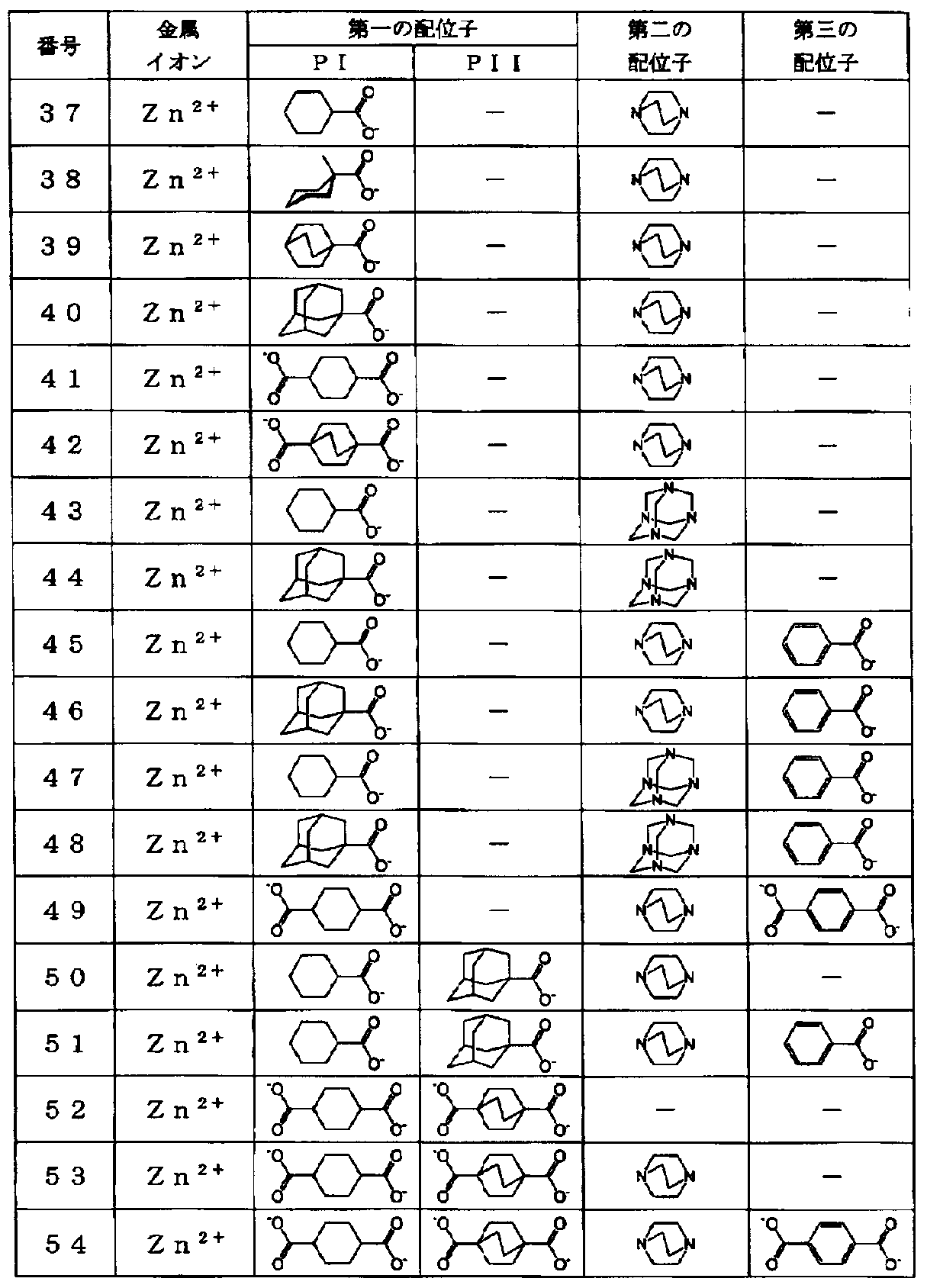
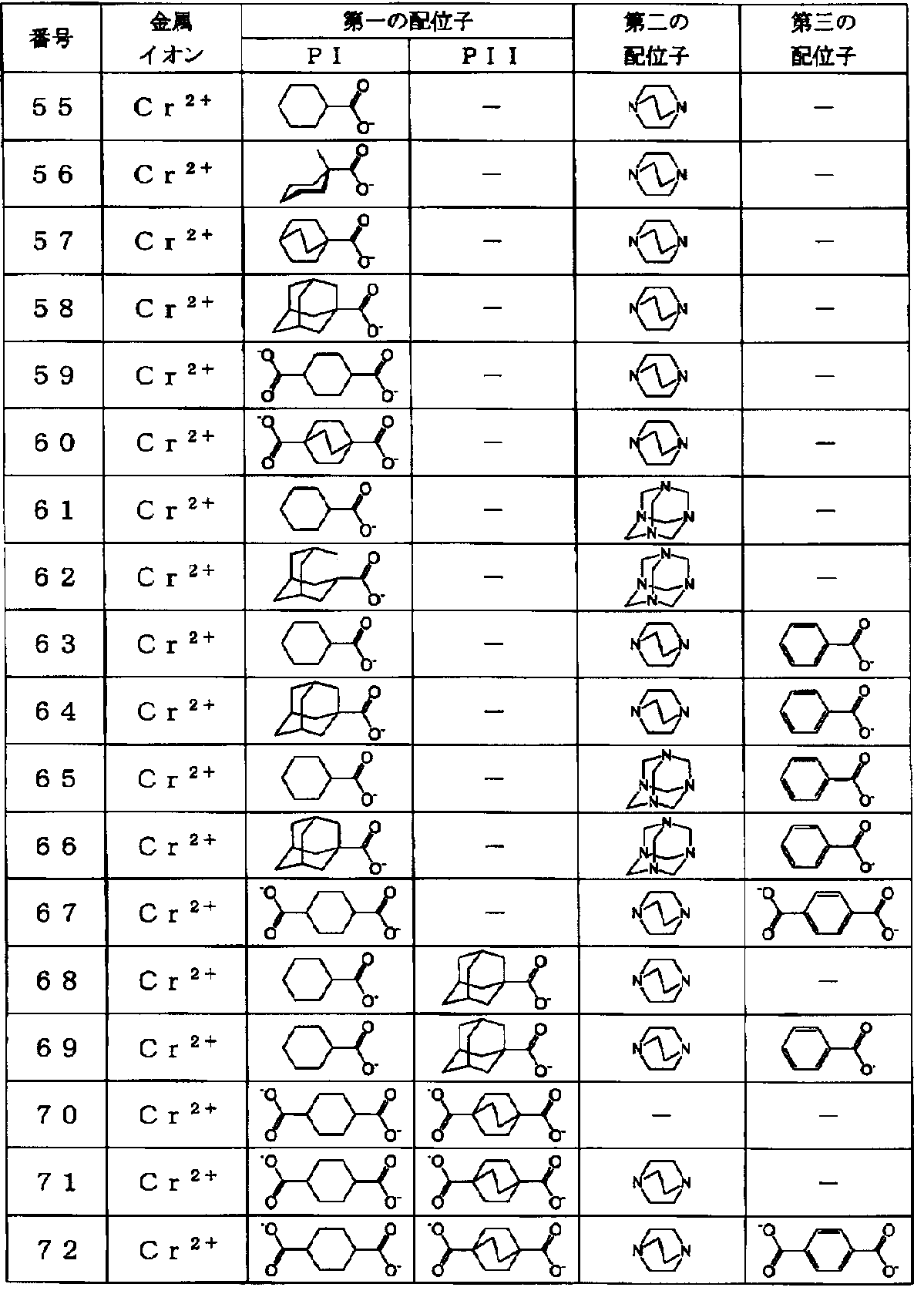
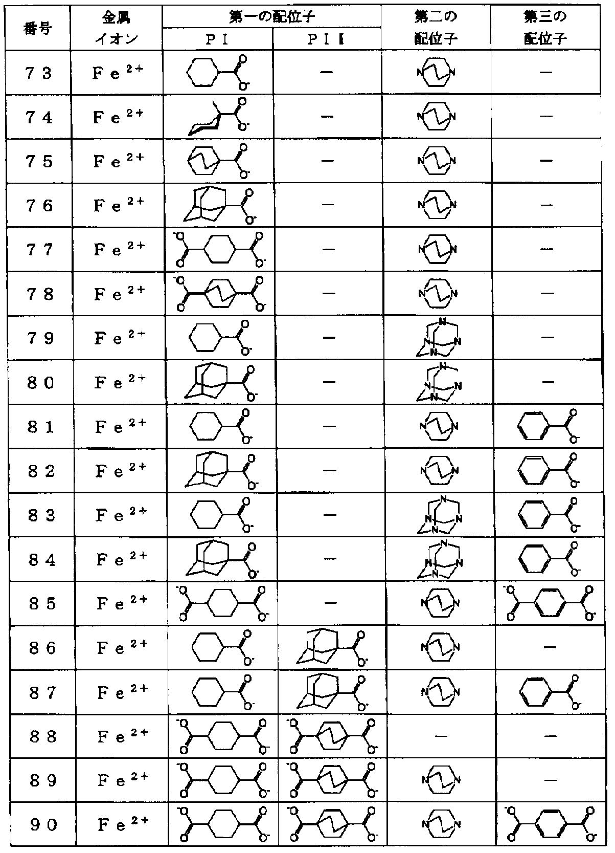

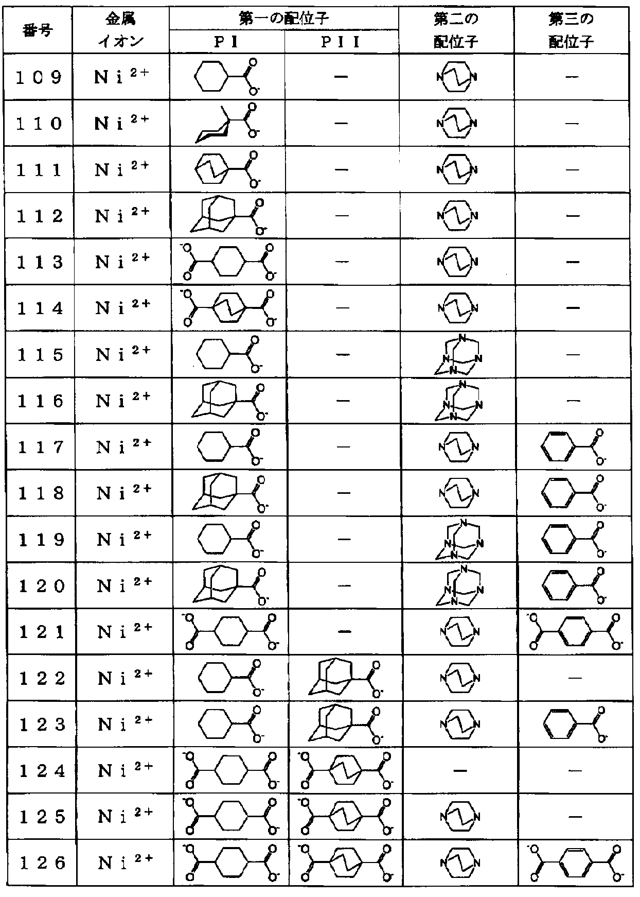
また、本発明において用いる金属錯体の製造方法としては、特に限定はないが、前記配位子又はそれらの前駆体(前記第一の配位子の前駆体と、必要に応じて前記第二の配位子及び/又は第三の配位子の前駆体)を、前記金属イオン(並びに必要に応じて、カウンターイオン及び結晶水)からなる金属塩又はその水和物と溶媒中で反応せしめることにより製造することが好ましい。ここで用いる溶媒としては、水、メタノール、エタノール、2-プロパノール、テトラヒドロフラン、アセトン、アセトニトリル、N,N-ジメチルアセトアミド、N,N-ジエチルアセトアミド、クロロホルム等の溶媒を使用でき、また、前記溶媒とは別の前記補助配位子をさらに加えてもよい。
なお、前記第一の配位子の前駆体と前記第三の配位子の前駆体における官能基としては、「-CO2A」、「-CS2A」、「-C(=O)SA」、「-C(=O)N(RA)A」、「-SO2A」、「-PO4(RA)A」、「-C≡N」、「-SA」、「-OA」及び「-N(RA)A」からなる群から選択されるいずれかで表される基が例示される。ここで、Aは、水素原子、アルカリ金属原子又はアルキル基で置換されていてもよいアンモニウムイオンであり、好ましくは水素原子である。
前記金属錯体の製造において、反応せしめる、前記第一の配位子の前駆体、前記第二の配位子、前記第三の配位子の前駆体及び前記金属塩のモル比は、各配位子の配位能力の強弱に従って調節する必要がある。
また、反応せしめる、前記第一の配位子の前駆体と前記第三の配位子の前駆体との好ましい比は、製造しようとする金属錯体に含まれる前記第一の配位子と前記第三の配位子との比に基づいても調節する必要がある。さらに、反応せしめる配位子又はそれらの前駆体は、金属塩に比して量論比より過剰にすることで、収率を向上させられる場合がある。また、高濃度で反応を実施することで、過剰に用いる配位子量を削減することができる場合もある。
前記金属塩として好ましくは、弗化物、塩化物、臭化物、硝酸塩、硫酸塩、過塩素酸塩、酢酸塩、テトラフルオロホウ酸塩、テトラフェニルホウ酸塩、ヘキサフルオロリン酸塩、ヘキサフルオロケイ酸塩、これらの水和物又はそれらの組み合わせが挙げられる。入手性がよく、かつカウンターアニオンの配位力が目的とする反応の妨げにならない程度に低いことが好ましいことから、好ましくは硝酸塩、硫酸塩、過塩素酸塩、酢酸塩、テトラフルオロホウ酸塩、ヘキサフルオロリン酸塩又はそれらの水和物であり、より好ましくは硝酸塩、硫酸塩、酢酸塩又はそれらの水和物である。
前記配位子又はそれらの前駆体を前記金属塩と反応せしめる際の反応温度は0℃以上200℃以下が好ましく、10℃以上150℃以下がより好ましく、10℃以上100℃以下がさらに好ましく、20℃以上60℃以下が特に好ましい。係る反応は、0.01~10MPaの圧力下で行うことが好ましく、0.05~1MPaの圧力下で行うことがより好ましく、0.08~0.12MPaの圧力下で行うことがさらに好ましく、通常、常圧下で行われる。反応時間は、通常1分~1週間、好ましくは5分~120時間である。
このような反応に用いる反応容器としては、開放型容器でも、オートクレーブなどの密閉型容器でも使用可能である。反応容器の加熱は、液体又は気体の熱媒を用いたり、マイクロ波や超音波を照射したりすることによって行うことができる。
また、前記反応において溶媒として適切なものを選択すると、生成した金属錯体は沈殿物として反応溶液中に析出する。析出した金属錯体を濾過などにより捕集した後、反応に用いた溶媒と同じ種類の溶媒、又は反応に用いた溶媒よりも揮発性が高い溶媒を用いて、析出した金属錯体を洗浄することが好ましい。さらに、得られた金属錯体が多孔性となっている場合は、細孔部に溶媒が吸着していることがあるため、これらを除去するために、金属錯体を乾燥することが好ましい。係る乾燥としては、室温又は加熱条件下での減圧乾燥が好ましい。
なお、前記第二の配位子を有する金属錯体を得る場合は、前記第一の配位子の前駆体(及び必要に応じて前記第三の配位子の前駆体)と前記金属塩とで予め中間体を合成し、次いで、その中間体に前記第二の配位子を加えて前記金属錯体を得るといった、段階的な合成方法を採用することもできる。
本発明の吸着方法においては、前述の金属錯体に、炭素数が3以下の飽和炭化水素と不飽和炭化水素とを含む混合物を接触せしめることにより、前記飽和炭化水素を前記金属錯体に選択的に吸着させるものである。係る金属錯体は、一種でも、二種以上を含んでいてもよい。
ここでいう飽和炭化水素は、エタン、プロパン、シクロプロパンであり、エタン及びプロパンが好ましい。また不飽和炭化水素は、エチレン、プロピレン、シクロプロペン、アセチレンが挙げられるが、エチレン及びプロピレンが好ましい。本発明において前記金属錯体に接触させる飽和炭化水素と飽和炭化水素は、炭素数が3以下の飽和炭化水素と不飽和炭化水素とを含む混合物であり、かかる混合物が気体であることが好ましい。また、飽和炭化水素及び不飽和炭化水素の炭素数は、同一又は飽和炭化水素の炭素数が多いことが好ましい。具体例としては、エタン及びエチレンの混合物、プロパン及びエチレンの混合物、並びにプロパン及びプロピレンの混合物が挙げられ、より好ましくプロパン及びプロピレンの混合物である。
本発明の吸着方法を用いることで、前記の飽和炭化水素と不飽和炭化水素との混合物を分離することも可能である。次に、本発明の炭化水素の分離方法について説明する。
本発明の炭化水素の分離方法は、前記本発明の飽和炭化水素の吸着方法を利用して前記飽和炭化水素と前記不飽和炭化水素とを分離する工程を有する、炭化水素の分離方法である。
本発明の分離方法により分離して得られる飽和炭化水素又は不飽和炭化水素は、組成比が分離前の混合物と異なっていればよいが、分離取得物は、いずれか一方が80mol%以上であることが好ましく、90mol%以上であることがより好ましく、95%以上であることがさらに好ましく、98%以上であることが特に好ましい。
本発明の分離方法において、前記金属錯体をそのまま、あるいは適当に粉砕することで粉末状にして用いることもできるが、適切な成型手段により成型して成型体として用いてもよい。なお、この成型において成型剤を用いる場合には、成型後に得られる吸着剤の炭化水素ガス吸着特性及び吸着後の炭化水素ガス脱離特性が著しく損なわれないようにして、成型剤の種類及びその使用量を定めることが好ましい。このような成型手段としてはプレス成型が例示される。吸着剤として用いる場合の成型体の形状は、吸着剤に要求される強度を維持できるような形状であることが望ましい。また、炭化水素ガス吸着速度を向上するので、成型品の表面積が大きいことが好ましい。
本発明において前述の金属錯体を用いて前記不飽和炭化水素と前記飽和炭化水素とを分離する具体的プロセスとしては、例えば、圧力スイング吸着法(圧力変動吸着法:Pressure Swing Adsorption)や温度スイング吸着法(温度変動吸着法:Temperature Swing Adsorption)や透過分離法(膜分離)が挙げられ、圧力スイング吸着法が好ましい。
圧力スイング吸着法においては、前記金属錯体に、第1の所定圧力(吸着圧力)の下で前記不飽和炭化水素と飽和炭化水素との混合物を接触せしめ、前記飽和炭化水素を前記金属錯体に選択的に吸着させる吸着工程を含むことが好ましい。このような吸着工程においては、前記金属錯体が配置された空間(例えば、吸着槽内)の圧力を事前に所望の吸着圧力まで上昇又は低減させた後、前記混合物をその吸着圧力の下で前記空間に導入し、飽和炭化水素が高選択的に前記金属錯体に吸着されて濃縮され、その炭化水素の減損分と不飽和炭化水素が前記空間から排出される。
また、このような圧力スイング吸着法においては、前記吸着工程の後に、圧力を第2の所定圧力(脱離圧力)に変化させ、前記金属錯体に吸着している炭化水素を脱離させる脱離工程を更に含むことがより好ましい。このような脱離工程(再生工程)においては、一方の炭化水素を選択的に吸着している金属錯体が配置された空間の圧力を所望の脱離圧力まで低減し、金属錯体に吸着されている前記飽和炭化水素の濃縮分を前記金属錯体から脱離せしめることによって前記空間から排出される。
圧力を第2の所定圧力(脱離圧力)に変化させる前に、少量の飽和炭化水素をフィードすることで、前記空間の不飽和炭化水素を飽和炭化水素に置換してもよい。
なお、このような圧力スイング吸着法では、得られる飽和炭化水素又は不飽和炭化水素の純度が低く、より高純度の前記飽和炭化水素又は前記不飽和炭化水素を得るための工夫が必要な場合には、二段以上とすることができ、その場合は前記吸着工程と前記脱離工程とが二回以上繰り返して行われることになる。
前記の圧力スイング吸着法における吸着条件は、分離対象及び用いる金属錯体によって決定されるが、吸着温度は173~373Kが好ましく、223~353Kがより好ましい。さらに好ましくは253~353Kであり、より好ましくは273~333Kである。吸着圧力は実施温度及び用いる金属錯体によって異なるが、3kPa~3MPaが好ましく、10kPa~2MPaがより好ましい。さらに好ましくは30kPa~2MPaであり、特に好ましくは100kPa~2MPaである。
また、前記吸着圧力としては、一方の炭化水素の吸着量と他方の炭化水素の吸着量との差が大きくなる圧力が採用され、好ましくは2倍以上、より好ましくは5倍以上、さらに好ましくは10倍以上になる圧力が採用される。他方、前記脱離圧力としては、飽和炭化水素の吸着量が、飽和吸着量に対し50%以下になる圧力が採用され、好ましくは20%以下、より好ましくは10%以下、さらに好ましくは5%以下になる圧力が採用される。
前記の圧力スイング吸着法における吸着成分の脱離条件は分離対象及び用いる金属錯体によって決定される。脱離圧力は分離対象、実施温度及び用いる金属錯体によって異なるが、気体の回収圧力が過度に低い場合、気体の貯蔵或いは利用のためには再圧縮の負荷が必要となることから、比較的高い圧力で回収することが好ましい。このような圧力としては、2kPa以上であることが好ましく、5kPa以上であることがより好ましい。さらに好ましくは10kPa~2MPaであり、特に好ましくは20kPa~1.5MPaである。本発明の飽和炭化水素の吸着方法によれば、このように実用上過度の低圧化を要しないで用いることができる圧力領域において吸着した気体を回収することができる。
また、脱離温度は223~373Kが好ましい。脱離工程では必ずしも積極的に昇温する必要はないが、脱離に必要な潜熱を補うことは好ましく、温調及び保温の実施は好ましい場合もある。
次に、本発明の分離方法を実施するのに好適な本発明の炭化水素の分離装置について説明する。かかる分離装置は、前述の金属錯体を備える分離手段と、前記分離手段に炭素数が3以下の飽和炭化水素と不飽和炭化水素とを含む混合物を導入する導入手段と、を備えており、前記金属錯体に前記混合物を接触せしめることにより前記飽和炭化水素を前記金属錯体に選択的に吸着させ、前記飽和炭化水素と前記不飽和炭化水素とを分離する装置である。
また、この炭化水素の分離装置においては、前記分離手段において前記金属錯体が配置された空間の圧力を制御する圧力制御手段を更に備えていることが好ましく、前記圧力制御手段により第1の所定圧力の下で前記混合物を前記金属錯体に接触せしめ、一方の炭化水素を前記金属錯体に選択的に吸着させることにより、前述の吸着工程が実施できるようになっていることが好ましい。
さらに、その場合、飽和炭化水素を前記金属錯体に選択的に吸着させた後に、前記圧力制御手段により圧力を第2の所定圧力に変化させ、前記金属錯体に吸着している飽和炭化水素を脱離させることにより、前述の脱離工程が実施できるようになっていることが好ましい。
図1に、この炭化水素の分離装置の好適な一実施形態を示す。
図1に示す分離装置(圧力スイング吸着装置の一例)においては、前述の金属錯体が充填された吸着槽(分離手段)1が配置されており、その一端にバルブV1を有する導入管P1を介して圧縮機2(導入手段)が接続され、さらに圧縮機2にはバルブV2を有する原料ガス(前記混合物)の導入管P2とバルブV3を有するパージガスの導入管P3とが接続されている。また、吸着槽1の他端には、バルブV4を有する排出管P4を介して減圧機3(圧力制御手段)が接続され、さらに減圧機3にはバルブV5を有する製品ガス(分離された炭化水素)の排出管P5とバルブV6を有するパージガスの排出管P6とが接続されている。さらに、圧縮機2、減圧機3、バルブV1~V6には制御手段4(例えば、PLC)が電気的に接続されており、それらの動作を制御することができるように構成されている。また、本発明の分離装置は、温度を制御できる温度制御手段を更に備えていることが好ましい。
図1に示す分離装置を用いて炭化水素を分離する場合、例えば以下のように制御される。すなわち、先ず、吸着槽1内に圧縮機2によりパージガスが導入された後、減圧機3により吸着槽1内の圧力が前記第1の所定圧力(吸着圧力)となるように減圧される。次いで、その圧力の下で吸着槽1内に圧縮機2により原料ガスが導入され、飽和炭化水素が選択的に前記金属錯体に吸着されて濃縮し、その炭化水素の減損分と不飽和炭化水素が第一の製品ガスとして排出される。
次に、減圧機3により吸着槽1内の圧力を前記第2の所定圧力(脱離圧力)まで減圧し、それにより前記金属錯体に吸着されていた飽和炭化水素の濃縮分が金属錯体から脱離して第二の製品ガスとして排出される。
以上、炭化水素の分離装置の好適な一実施形態について説明したが、上記実施形態に限定されるものではなく、例えば、圧縮機と減圧機の一方が導入手段と圧力制御手段とを兼ねる場合はいずれか一方のみでもよい。また、金属錯体が充填された吸着槽として、複数の吸着槽(吸着塔)が並列又は直列に接続されていてもよい。
以下、本発明を実施例によって具体的に説明するが、本発明はこれらに限定されるものではない。以下の実施例及び比較例における分析及び評価はそれぞれ次のようにして行った。
(1)粉末X線回折パターンの測定
粉末X線装置を用いて、回折角(2θ)=3~40°の範囲を走査速度2°/分で走査し、対称反射法で測定した。測定条件の詳細を以下に示す。
<測定条件>
装置:株式会社リガク製RINT-UltimaIII
X線源:CuKα(λ=1.5418Å) 40kV 40mA
ゴニオメーター:水平ゴニオメーター
検出器:シンチレーションカウンター
ステップ幅:0.02°
スリット:発散スリット=1mm
発散縦制限スリット=10mm
受光スリット=開放
散乱スリット=開放。
粉末X線装置を用いて、回折角(2θ)=3~40°の範囲を走査速度2°/分で走査し、対称反射法で測定した。測定条件の詳細を以下に示す。
<測定条件>
装置:株式会社リガク製RINT-UltimaIII
X線源:CuKα(λ=1.5418Å) 40kV 40mA
ゴニオメーター:水平ゴニオメーター
検出器:シンチレーションカウンター
ステップ幅:0.02°
スリット:発散スリット=1mm
発散縦制限スリット=10mm
受光スリット=開放
散乱スリット=開放。
(2)元素分析
炭素、水素及び窒素については、炭素・水素・窒素同時測定装置を用いて定量した。測定条件の詳細を以下に示す。
炭素、水素及び窒素については、炭素・水素・窒素同時測定装置を用いて定量した。測定条件の詳細を以下に示す。
<測定条件>
≪炭素・水素・窒素≫
装置:株式会社ジェイ・サイエンス・ラボ製MICRO CORDER JM10
燃焼温度:950℃
燃焼時間:4分。
≪炭素・水素・窒素≫
装置:株式会社ジェイ・サイエンス・ラボ製MICRO CORDER JM10
燃焼温度:950℃
燃焼時間:4分。
(3)吸脱着等温線の測定
自動比表面積/細孔分布測定装置を用いて容量法で測定を行った。このとき、測定に先立って試料を373K、5Paで16時間乾燥し、吸着水などを除去した。測定条件の詳細を以下に示す。
<測定条件>
装置:日本ベル株式会社製BELSORP-miniII
圧力プログラム:5kPa以下→120kPa→10kPa以下
平衡待ち時間:300秒。
自動比表面積/細孔分布測定装置を用いて容量法で測定を行った。このとき、測定に先立って試料を373K、5Paで16時間乾燥し、吸着水などを除去した。測定条件の詳細を以下に示す。
<測定条件>
装置:日本ベル株式会社製BELSORP-miniII
圧力プログラム:5kPa以下→120kPa→10kPa以下
平衡待ち時間:300秒。
また、以下の合成例で用いる[Cu2(chc)4]、[Cu2(bza)4]、[Cu2(adc)4(H2O)2]、[Cu2(Fbza)4]及び[Cu2(F5bza)4]は、以下の文献:
J.Chem.Soc.,1965,P.6466-6477
に記載の方法に準拠して合成した。[Cu2(chc)4],[Cu2(bza)4]、[Cu2(Fbza)4]及び[Cu2(F5bza)4]の構造式を以下に示す。
J.Chem.Soc.,1965,P.6466-6477
に記載の方法に準拠して合成した。[Cu2(chc)4],[Cu2(bza)4]、[Cu2(Fbza)4]及び[Cu2(F5bza)4]の構造式を以下に示す。
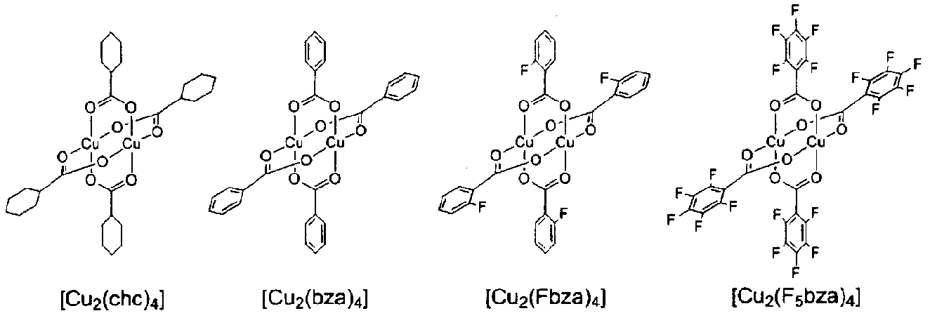
また、以下の合成例で用いる[Cu2(adc)4(H2O)2]の構造式を以下に示す。

(合成例1)
大気下、[Cu2(chc)4]0.250g(0.395mmol)にメタノール50mLに加え298Kで30分間攪拌した後、この溶液に1,4-ジアザビシクロ[2.2.2]オクタン0.047g(0.415mmol)を加えた。その後、298Kで24時間攪拌した。析出した金属錯体を吸引濾過により回収した後、メタノールで洗浄し、さらに298K、5Paで2時間乾燥し、目的の金属錯体0.2454g(収率83%)を得た。得られた金属錯体の粉末X線回折パターンを図2に示す。図2に示した結果から、得られた金属錯体は規則構造を有することが確認された。また、元素分析を行った結果、その組成比(モル比)は、銅イオン:シクロヘキサンカルボキシレートイオン:1,4-ジアザビシクロ[2.2.2]オクタン=2:4:1であった。
実測値 C:52.68,H:7.41,N:3.25(%)
理論値 C:54.60,H:7.55,N:3.75(%)。
大気下、[Cu2(chc)4]0.250g(0.395mmol)にメタノール50mLに加え298Kで30分間攪拌した後、この溶液に1,4-ジアザビシクロ[2.2.2]オクタン0.047g(0.415mmol)を加えた。その後、298Kで24時間攪拌した。析出した金属錯体を吸引濾過により回収した後、メタノールで洗浄し、さらに298K、5Paで2時間乾燥し、目的の金属錯体0.2454g(収率83%)を得た。得られた金属錯体の粉末X線回折パターンを図2に示す。図2に示した結果から、得られた金属錯体は規則構造を有することが確認された。また、元素分析を行った結果、その組成比(モル比)は、銅イオン:シクロヘキサンカルボキシレートイオン:1,4-ジアザビシクロ[2.2.2]オクタン=2:4:1であった。
実測値 C:52.68,H:7.41,N:3.25(%)
理論値 C:54.60,H:7.55,N:3.75(%)。
なお、合成例1において得られた金属錯体の構造(一次元構造)は、以下の構造式に示す構造であると考えられる。

(合成例2)
大気下、[Cu2(chc)4]0.284g(0.45mmol)にクロロホルム:メタノールが5:1である溶液70mLを加え298Kで5分間攪拌して溶解させ、これを溶液Aとした。続いて、[Cu2(bza)4]0.030g(0.05mmol)にクロロホルム:メタノールが5:1である溶液10mLを加え298Kで5分間攪拌して溶解させ、これを溶液Bとした。溶液Bを溶液Aに加え、298Kで10分間攪拌した後1,4-ジアザビシクロ[2.2.2]オクタン0.056g(0.5mmol)を加え、298Kで24時間攪拌した。析出した金属錯体を吸引濾過により回収した後、クロロホルムで洗浄し、さらに298K、5Paで2時間乾燥し、目的の金属錯体0.3129g(収率83%)を得た。得られた金属錯体の粉末X線回折パターンを図3に示す。図3に示した結果から、得られた金属錯体は規則構造を有することが確認された。また、元素分析を行った結果、その組成比(モル比)は、銅イオン:シクロヘキサンカルボキシレートイオン:ベンゼンカルボキシレートイオン:1,4-ジアザビシクロ[2.2.2]オクタン=2:3.6:0.4:1であった。
実測値 C:54.47,H:7.04,N:3.61(%)
理論値 C:54.78,H:7.25,N:3.76(%)。
大気下、[Cu2(chc)4]0.284g(0.45mmol)にクロロホルム:メタノールが5:1である溶液70mLを加え298Kで5分間攪拌して溶解させ、これを溶液Aとした。続いて、[Cu2(bza)4]0.030g(0.05mmol)にクロロホルム:メタノールが5:1である溶液10mLを加え298Kで5分間攪拌して溶解させ、これを溶液Bとした。溶液Bを溶液Aに加え、298Kで10分間攪拌した後1,4-ジアザビシクロ[2.2.2]オクタン0.056g(0.5mmol)を加え、298Kで24時間攪拌した。析出した金属錯体を吸引濾過により回収した後、クロロホルムで洗浄し、さらに298K、5Paで2時間乾燥し、目的の金属錯体0.3129g(収率83%)を得た。得られた金属錯体の粉末X線回折パターンを図3に示す。図3に示した結果から、得られた金属錯体は規則構造を有することが確認された。また、元素分析を行った結果、その組成比(モル比)は、銅イオン:シクロヘキサンカルボキシレートイオン:ベンゼンカルボキシレートイオン:1,4-ジアザビシクロ[2.2.2]オクタン=2:3.6:0.4:1であった。
実測値 C:54.47,H:7.04,N:3.61(%)
理論値 C:54.78,H:7.25,N:3.76(%)。
(合成例3)
大気下、[Cu2(chc)4]0.253g(0.4mmol)にクロロホルム:メタノールが5:1である溶液60mLを加え298Kで5分間攪拌して溶解させ、これを溶液Aとした。続いて、[Cu2(bza)4]0.061g(0.1mmol)にクロロホルム:メタノールが5:1である溶液15mLを加え298Kで5分間攪拌して溶解させ、これを溶液Bとした。溶液Bを溶液Aに加え、298Kで10分間攪拌した後1,4-ジアザビシクロ[2.2.2]オクタン0.056g(0.5mmol)を加え、298Kで24時間攪拌した。析出した金属錯体を吸引濾過により回収した後、クロロホルムで洗浄し、さらに298K、5Paで2時間乾燥し、目的の金属錯体0.2913g(収率78%)を得た。得られた金属錯体の粉末X線回折パターンを図4に示す。図4に示した結果から、得られた金属錯体は規則構造を有することが確認された。また、元素分析を行った結果、その組成比(モル比)は、銅イオン:シクロヘキサンカルボキシレートイオン:ベンゼンカルボキシレートイオン:1,4-ジアザビシクロ[2.2.2]オクタン=2:3.2:0.8:1であった。
実測値 C:54.63,H:6.89,N:3.68(%)
理論値 C:54.96,H:6.94,N:3.77(%)。
大気下、[Cu2(chc)4]0.253g(0.4mmol)にクロロホルム:メタノールが5:1である溶液60mLを加え298Kで5分間攪拌して溶解させ、これを溶液Aとした。続いて、[Cu2(bza)4]0.061g(0.1mmol)にクロロホルム:メタノールが5:1である溶液15mLを加え298Kで5分間攪拌して溶解させ、これを溶液Bとした。溶液Bを溶液Aに加え、298Kで10分間攪拌した後1,4-ジアザビシクロ[2.2.2]オクタン0.056g(0.5mmol)を加え、298Kで24時間攪拌した。析出した金属錯体を吸引濾過により回収した後、クロロホルムで洗浄し、さらに298K、5Paで2時間乾燥し、目的の金属錯体0.2913g(収率78%)を得た。得られた金属錯体の粉末X線回折パターンを図4に示す。図4に示した結果から、得られた金属錯体は規則構造を有することが確認された。また、元素分析を行った結果、その組成比(モル比)は、銅イオン:シクロヘキサンカルボキシレートイオン:ベンゼンカルボキシレートイオン:1,4-ジアザビシクロ[2.2.2]オクタン=2:3.2:0.8:1であった。
実測値 C:54.63,H:6.89,N:3.68(%)
理論値 C:54.96,H:6.94,N:3.77(%)。
(合成例4)
大気下、[Cu2(chc)4]0.158g(0.250mmol)にクロロホルム:メタノールが5:1である溶液35mLを加え298Kで5分間攪拌して溶解させ、これを溶液Aとした。続いて、[Cu2(bza)4]0.153g(0.250mmol)にクロロホルム:メタノールが5:1である溶液30mLを加え298Kで5分間攪拌して溶解させ、これを溶液Bとした。溶液Bを溶液Aに加え、298Kで10分間攪拌した後1,4-ジアザビシクロ[2.2.2]オクタン0.056g(0.5mmol)を加え、298Kで24時間攪拌した。析出した金属錯体を吸引濾過により回収した後、クロロホルムで洗浄し、さらに298K、5Paで2時間乾燥し、目的の金属錯体0.2737g(収率74%)を得た。得られた金属錯体の粉末X線回折パターンを図5に示す。図5に示した結果から、得られた金属錯体は規則構造を有することが確認された。また、元素分析を行った結果、その組成比(モル比)は、銅イオン:シクロヘキサンカルボキシレートイオン:ベンゼンカルボキシレートイオン:1,4-ジアザビシクロ[2.2.2]オクタン=2:2:2:1であった。
実測値 C:54.66,H:5.86,N:3.74(%)
理論値 C:55.50,H:6.03,N:3.81(%)。
大気下、[Cu2(chc)4]0.158g(0.250mmol)にクロロホルム:メタノールが5:1である溶液35mLを加え298Kで5分間攪拌して溶解させ、これを溶液Aとした。続いて、[Cu2(bza)4]0.153g(0.250mmol)にクロロホルム:メタノールが5:1である溶液30mLを加え298Kで5分間攪拌して溶解させ、これを溶液Bとした。溶液Bを溶液Aに加え、298Kで10分間攪拌した後1,4-ジアザビシクロ[2.2.2]オクタン0.056g(0.5mmol)を加え、298Kで24時間攪拌した。析出した金属錯体を吸引濾過により回収した後、クロロホルムで洗浄し、さらに298K、5Paで2時間乾燥し、目的の金属錯体0.2737g(収率74%)を得た。得られた金属錯体の粉末X線回折パターンを図5に示す。図5に示した結果から、得られた金属錯体は規則構造を有することが確認された。また、元素分析を行った結果、その組成比(モル比)は、銅イオン:シクロヘキサンカルボキシレートイオン:ベンゼンカルボキシレートイオン:1,4-ジアザビシクロ[2.2.2]オクタン=2:2:2:1であった。
実測値 C:54.66,H:5.86,N:3.74(%)
理論値 C:55.50,H:6.03,N:3.81(%)。
(合成例5)
大気下、[Cu2(chc)4]0.063g(0.1mmol)にクロロホルム:メタノールが5:1である溶液15mLを加え298Kで5分間攪拌して溶解させ、これを溶液Aとした。続いて、[Cu2(bza)4]0.245g(0.4mmol)にクロロホルム:メタノールが5:1である溶液60mLを加え298Kで5分間攪拌して溶解させ、これを溶液Bとした。溶液Bを溶液Aに加え、298Kで10分間攪拌した後1,4-ジアザビシクロ[2.2.2]オクタン0.056g(0.5mmol)を加え、298Kで24時間攪拌した。析出した金属錯体を吸引濾過により回収した後、クロロホルムで洗浄し、さらに298K、5Paで2時間乾燥し、目的の金属錯体0.1933g(収率53%)を得た。得られた金属錯体の粉末X線回折パターンを図6に示す。図6に示した結果から、得られた金属錯体は規則構造を有することが確認された。また、元素分析を行った結果、その組成比(モル比)は、銅イオン:シクロヘキサンカルボキシレートイオン:ベンゼンカルボキシレートイオン:1,4-ジアザビシクロ[2.2.2]オクタン=2:0.8:3.2:1であった。
実測値 C:55.86,H:5.01,N:3.83(%)
理論値 C:56.05,H:5.09,N:3.85(%)。
大気下、[Cu2(chc)4]0.063g(0.1mmol)にクロロホルム:メタノールが5:1である溶液15mLを加え298Kで5分間攪拌して溶解させ、これを溶液Aとした。続いて、[Cu2(bza)4]0.245g(0.4mmol)にクロロホルム:メタノールが5:1である溶液60mLを加え298Kで5分間攪拌して溶解させ、これを溶液Bとした。溶液Bを溶液Aに加え、298Kで10分間攪拌した後1,4-ジアザビシクロ[2.2.2]オクタン0.056g(0.5mmol)を加え、298Kで24時間攪拌した。析出した金属錯体を吸引濾過により回収した後、クロロホルムで洗浄し、さらに298K、5Paで2時間乾燥し、目的の金属錯体0.1933g(収率53%)を得た。得られた金属錯体の粉末X線回折パターンを図6に示す。図6に示した結果から、得られた金属錯体は規則構造を有することが確認された。また、元素分析を行った結果、その組成比(モル比)は、銅イオン:シクロヘキサンカルボキシレートイオン:ベンゼンカルボキシレートイオン:1,4-ジアザビシクロ[2.2.2]オクタン=2:0.8:3.2:1であった。
実測値 C:55.86,H:5.01,N:3.83(%)
理論値 C:56.05,H:5.09,N:3.85(%)。
(合成例6)
大気下、[Cu2(chc)4]0.191g(0.3mmol)にクロロホルム:メタノールが5:1である溶液42mLを加え298Kで5分間攪拌して溶解させ、これを溶液Aとした。続いて、[Cu2(adc)4(H2O)2]0.088g(0.1mmol)にクロロホルム:メタノールが40:1である溶液16mLを加え298Kで5分間攪拌して溶解させ、これを溶液Bとした。溶液Bを溶液Aに加え、298Kで10分間攪拌した後1,4-ジアザビシクロ[2.2.2]オクタン0.045g(0.4mmol)を加え、298Kで24時間攪拌した。析出した金属錯体を吸引濾過により回収した後、クロロホルムで洗浄し、さらに298K、5Paで2時間乾燥し、目的の金属錯体0.2491g(収率77%)を得た。得られた金属錯体の粉末X線回折パターンを図7に示す。図7に示した結果から、得られた金属錯体は規則構造を有することが確認された。また、元素分析を行った結果、その組成比(モル比)は、銅イオン:シクロヘキサンカルボキシレートイオン:アダマンタンカルボキシレートイオン:1,4-ジアザビシクロ[2.2.2]オクタン=2:3:1:1であった。
実測値 C:56.91,H:7.68,N:3.39(%)
理論値 C:57.05,H:7.56,N:3.50(%)。
大気下、[Cu2(chc)4]0.191g(0.3mmol)にクロロホルム:メタノールが5:1である溶液42mLを加え298Kで5分間攪拌して溶解させ、これを溶液Aとした。続いて、[Cu2(adc)4(H2O)2]0.088g(0.1mmol)にクロロホルム:メタノールが40:1である溶液16mLを加え298Kで5分間攪拌して溶解させ、これを溶液Bとした。溶液Bを溶液Aに加え、298Kで10分間攪拌した後1,4-ジアザビシクロ[2.2.2]オクタン0.045g(0.4mmol)を加え、298Kで24時間攪拌した。析出した金属錯体を吸引濾過により回収した後、クロロホルムで洗浄し、さらに298K、5Paで2時間乾燥し、目的の金属錯体0.2491g(収率77%)を得た。得られた金属錯体の粉末X線回折パターンを図7に示す。図7に示した結果から、得られた金属錯体は規則構造を有することが確認された。また、元素分析を行った結果、その組成比(モル比)は、銅イオン:シクロヘキサンカルボキシレートイオン:アダマンタンカルボキシレートイオン:1,4-ジアザビシクロ[2.2.2]オクタン=2:3:1:1であった。
実測値 C:56.91,H:7.68,N:3.39(%)
理論値 C:57.05,H:7.56,N:3.50(%)。
(合成例7)
大気下、[Cu2(chc)4]0.211g(0.33mmol)にクロロホルム:メタノールが5:1である溶液54mLを加え298Kで5分間攪拌して溶解させ、これを溶液Aとした。続いて、[Cu2(adc)4(H2O)2]0.073g(0.083mmol)にクロロホルム:メタノールが40:1である溶液16mLを加え298Kで5分間攪拌して溶解させ、これを溶液Bとした。溶液Bを溶液Aに加え、298Kで10分間攪拌した後1,4-ジアザビシクロ[2.2.2]オクタン0.046g(0.413mmol)を加え、298Kで24時間攪拌した。析出した金属錯体を吸引濾過により回収した後、クロロホルムで洗浄し、さらに298K、5Paで2時間乾燥し、目的の金属錯体0.2259g(収率70%)を得た。得られた金属錯体の粉末X線回折パターンを図8に示す。図8に示した結果から、得られた金属錯体は規則構造を有することが確認された。また、元素分析を行った結果、その組成比(モル比)は、銅イオン:シクロヘキサンカルボキシレートイオン:アダマンタンカルボキシレートイオン:1,4-ジアザビシクロ[2.2.2]オクタン=2:3.4:0.6:1であった。
実測値 C:56.23,H:7.60,N:3.65(%)
理論値 C:56.11,H:7.55,N:3.60(%)。
大気下、[Cu2(chc)4]0.211g(0.33mmol)にクロロホルム:メタノールが5:1である溶液54mLを加え298Kで5分間攪拌して溶解させ、これを溶液Aとした。続いて、[Cu2(adc)4(H2O)2]0.073g(0.083mmol)にクロロホルム:メタノールが40:1である溶液16mLを加え298Kで5分間攪拌して溶解させ、これを溶液Bとした。溶液Bを溶液Aに加え、298Kで10分間攪拌した後1,4-ジアザビシクロ[2.2.2]オクタン0.046g(0.413mmol)を加え、298Kで24時間攪拌した。析出した金属錯体を吸引濾過により回収した後、クロロホルムで洗浄し、さらに298K、5Paで2時間乾燥し、目的の金属錯体0.2259g(収率70%)を得た。得られた金属錯体の粉末X線回折パターンを図8に示す。図8に示した結果から、得られた金属錯体は規則構造を有することが確認された。また、元素分析を行った結果、その組成比(モル比)は、銅イオン:シクロヘキサンカルボキシレートイオン:アダマンタンカルボキシレートイオン:1,4-ジアザビシクロ[2.2.2]オクタン=2:3.4:0.6:1であった。
実測値 C:56.23,H:7.60,N:3.65(%)
理論値 C:56.11,H:7.55,N:3.60(%)。
(合成例8)
大気下、[Cu2(chc)4]0.222g(0.35mmol)にクロロホルム:メタノールが5:1である溶液48mLを加え298Kで5分間攪拌して溶解させ、これを溶液Aとした。続いて、[Cu2(adc)4(H2O)2]0.044g(0.05mmol)にクロロホルム:メタノールが40:1である溶液8mLを加え298Kで5分間攪拌して溶解させ、これを溶液Bとした。溶液Bを溶液Aに加え、298Kで10分間攪拌した後1,4-ジアザビシクロ[2.2.2]オクタン0.045g(0.4mmol)を加え、298Kで24時間攪拌した。析出した金属錯体を吸引濾過により回収した後、クロロホルムで洗浄し、さらに298K、5Paで2時間乾燥し、目的の金属錯体0.2632g(収率85%)を得た。得られた金属錯体の粉末X線回折パターンを図9に示す。図9に示した結果から、得られた金属錯体は規則構造を有することが確認された。また、元素分析を行った結果、その組成比(モル比)は、銅イオン:シクロヘキサンカルボキシレートイオン:アダマンタンカルボキシレートイオン:1,4-ジアザビシクロ[2.2.2]オクタン=2:3.6:0.4:1であった。
実測値 C:55.45,H:7.59,N:3.59(%)
理論値 C:55.62,H:7.55,N:3.64(%)。
大気下、[Cu2(chc)4]0.222g(0.35mmol)にクロロホルム:メタノールが5:1である溶液48mLを加え298Kで5分間攪拌して溶解させ、これを溶液Aとした。続いて、[Cu2(adc)4(H2O)2]0.044g(0.05mmol)にクロロホルム:メタノールが40:1である溶液8mLを加え298Kで5分間攪拌して溶解させ、これを溶液Bとした。溶液Bを溶液Aに加え、298Kで10分間攪拌した後1,4-ジアザビシクロ[2.2.2]オクタン0.045g(0.4mmol)を加え、298Kで24時間攪拌した。析出した金属錯体を吸引濾過により回収した後、クロロホルムで洗浄し、さらに298K、5Paで2時間乾燥し、目的の金属錯体0.2632g(収率85%)を得た。得られた金属錯体の粉末X線回折パターンを図9に示す。図9に示した結果から、得られた金属錯体は規則構造を有することが確認された。また、元素分析を行った結果、その組成比(モル比)は、銅イオン:シクロヘキサンカルボキシレートイオン:アダマンタンカルボキシレートイオン:1,4-ジアザビシクロ[2.2.2]オクタン=2:3.6:0.4:1であった。
実測値 C:55.45,H:7.59,N:3.59(%)
理論値 C:55.62,H:7.55,N:3.64(%)。
(合成例9)
大気下、[Cu2(chc)4]0.238g(0.375mmol)にクロロホルム:メタノールが5:1である溶液54mLを加え298Kで5分間攪拌して溶解させ、これを溶液Aとした。続いて、[Cu2(adc)4(H2O)2]0.022g(0.025mmol)にクロロホルム:メタノールが40:1である溶液4mLを加え298Kで5分間攪拌して溶解させ、これを溶液Bとした。溶液Bを溶液Aに加え、298Kで10分間攪拌した後1,4-ジアザビシクロ[2.2.2]オクタン0.045g(0.4mmol)を加え、298Kで24時間攪拌した。析出した金属錯体を吸引濾過により回収した後、クロロホルムで洗浄し、さらに298K、5Paで2時間乾燥し、目的の金属錯体0.2425g(収率79%)を得た。得られた金属錯体の粉末X線回折パターンを図10に示す。図10に示した結果から、得られた金属錯体は規則構造を有することが確認された。また、元素分析を行った結果、その組成比(モル比)は、銅イオン:シクロヘキサンカルボキシレートイオン:アダマンタンカルボキシレートイオン:1,4-ジアザビシクロ[2.2.2]オクタン=2:3.8:0.2:1であった。
実測値 C:54.72,H:7.51,N:3.51(%)
理論値 C:55.12,H:7.55,N:3.69(%)。
大気下、[Cu2(chc)4]0.238g(0.375mmol)にクロロホルム:メタノールが5:1である溶液54mLを加え298Kで5分間攪拌して溶解させ、これを溶液Aとした。続いて、[Cu2(adc)4(H2O)2]0.022g(0.025mmol)にクロロホルム:メタノールが40:1である溶液4mLを加え298Kで5分間攪拌して溶解させ、これを溶液Bとした。溶液Bを溶液Aに加え、298Kで10分間攪拌した後1,4-ジアザビシクロ[2.2.2]オクタン0.045g(0.4mmol)を加え、298Kで24時間攪拌した。析出した金属錯体を吸引濾過により回収した後、クロロホルムで洗浄し、さらに298K、5Paで2時間乾燥し、目的の金属錯体0.2425g(収率79%)を得た。得られた金属錯体の粉末X線回折パターンを図10に示す。図10に示した結果から、得られた金属錯体は規則構造を有することが確認された。また、元素分析を行った結果、その組成比(モル比)は、銅イオン:シクロヘキサンカルボキシレートイオン:アダマンタンカルボキシレートイオン:1,4-ジアザビシクロ[2.2.2]オクタン=2:3.8:0.2:1であった。
実測値 C:54.72,H:7.51,N:3.51(%)
理論値 C:55.12,H:7.55,N:3.69(%)。
(合成例10)
大気下、[Cu2(Fbza)4]0.137g(0.20mmol)にクロロホルム:メタノールが5:1である溶液28mLを加え298Kで5分間攪拌して溶解させ、これを溶液Aとした。続いて、[Cu2(chc)4]0.509g(0.80mmol)にクロロホルム:メタノールが5:1である溶液112mLを加え298Kで5分間攪拌して溶解させ、これを溶液Bとした。溶液Bを溶液Aに加え、298Kで10分間攪拌した後1,4-ジアザビシクロ[2.2.2]オクタン0.112g(1.0mmol)を加え、298Kで24時間攪拌した。析出した金属錯体を吸引濾過により回収した後、クロロホルム:メタノールが5:1である溶液で洗浄し、さらに298K、5Paで2時間乾燥し、目的の金属錯体0.6391g(収率84%)を得た。得られた金属錯体の粉末X線回折パターンを図21に示す。図21に示した結果から、得られた金属錯体は規則構造を有することが確認された。また、元素分析を行った結果、その組成比(モル比)は、銅イオン:シクロヘキサンカルボキシレートイオン:フルオロベンゼンカルボキシレートイオン:1,4-ジアザビシクロ[2.2.2]オクタン=2:3.2:0.8:1であった。
実測値 C:53.65,H:6.71,N:3.65(%)
理論値 C:53.91,H:6.71,N:3.70(%)。
大気下、[Cu2(Fbza)4]0.137g(0.20mmol)にクロロホルム:メタノールが5:1である溶液28mLを加え298Kで5分間攪拌して溶解させ、これを溶液Aとした。続いて、[Cu2(chc)4]0.509g(0.80mmol)にクロロホルム:メタノールが5:1である溶液112mLを加え298Kで5分間攪拌して溶解させ、これを溶液Bとした。溶液Bを溶液Aに加え、298Kで10分間攪拌した後1,4-ジアザビシクロ[2.2.2]オクタン0.112g(1.0mmol)を加え、298Kで24時間攪拌した。析出した金属錯体を吸引濾過により回収した後、クロロホルム:メタノールが5:1である溶液で洗浄し、さらに298K、5Paで2時間乾燥し、目的の金属錯体0.6391g(収率84%)を得た。得られた金属錯体の粉末X線回折パターンを図21に示す。図21に示した結果から、得られた金属錯体は規則構造を有することが確認された。また、元素分析を行った結果、その組成比(モル比)は、銅イオン:シクロヘキサンカルボキシレートイオン:フルオロベンゼンカルボキシレートイオン:1,4-ジアザビシクロ[2.2.2]オクタン=2:3.2:0.8:1であった。
実測値 C:53.65,H:6.71,N:3.65(%)
理論値 C:53.91,H:6.71,N:3.70(%)。
(合成例11)
大気下、[Cu2(chc)4]0.254g(0.40mmol)と[Cu2(F5bza)4]0.097g(0.10mmol)に脱水THF(テトラヒドロフラン)25mLを加え298Kで10分間攪拌して溶解させ、溶液Aとした。続いて、1,4-ジアザビシクロ[2.2.2]オクタン0.112g(0.50mmol)に脱水アセトン25mLを加え298Kで10分間攪拌して溶解させ、溶液Bとした。溶液Bを溶液Aに加え、298Kで24時間攪拌した。析出した金属錯体を吸引濾過により回収した後、脱水アセトンで洗浄し、さらに298K、5Paで2時間乾燥し、目的の金属錯体0.350g(収率86%)を得た。得られた金属錯体の粉末X線回折パターンを図22に示す。図22に示した結果から、得られた金属錯体は規則構造を有することが確認された。また、元素分析を行った結果、その組成比(モル比)は、銅イオン:シクロヘキサンカルボキシレートイオン:ペンタフルオロベンゼンカルボキシレートイオン:1,4-ジアザビシクロ[2.2.2]オクタン=2:3.2:0.8:1であった。
実測値 C:50.58,H:6.50,N:3.52(%)
理論値 C:50.10,H:5.84,N:3.44(%)。
大気下、[Cu2(chc)4]0.254g(0.40mmol)と[Cu2(F5bza)4]0.097g(0.10mmol)に脱水THF(テトラヒドロフラン)25mLを加え298Kで10分間攪拌して溶解させ、溶液Aとした。続いて、1,4-ジアザビシクロ[2.2.2]オクタン0.112g(0.50mmol)に脱水アセトン25mLを加え298Kで10分間攪拌して溶解させ、溶液Bとした。溶液Bを溶液Aに加え、298Kで24時間攪拌した。析出した金属錯体を吸引濾過により回収した後、脱水アセトンで洗浄し、さらに298K、5Paで2時間乾燥し、目的の金属錯体0.350g(収率86%)を得た。得られた金属錯体の粉末X線回折パターンを図22に示す。図22に示した結果から、得られた金属錯体は規則構造を有することが確認された。また、元素分析を行った結果、その組成比(モル比)は、銅イオン:シクロヘキサンカルボキシレートイオン:ペンタフルオロベンゼンカルボキシレートイオン:1,4-ジアザビシクロ[2.2.2]オクタン=2:3.2:0.8:1であった。
実測値 C:50.58,H:6.50,N:3.52(%)
理論値 C:50.10,H:5.84,N:3.44(%)。
(比較合成例1)
大気下、[Cu2(bza)4]0.245g(0.40mmol)にメタノール50mLを加え298Kで5分間攪拌して溶解させ、1,4-ジアザビシクロ[2.2.2]オクタン0.047g(0.42mmol)を加え、298Kで24時間攪拌した。析出した金属錯体を吸引濾過により回収した後、メタノールで洗浄し、さらに373K、5Paで3.5時間乾燥し、目的の金属錯体0.2484g(収率85%)を得た。得られた金属錯体の粉末X線回折パターンを図11に示す。図11に示した結果から、得られた金属錯体は規則構造を有することが確認された。また、元素分析を行った結果、その組成比(モル比)は、銅イオン:ベンゼンカルボキシレートイオン:1,4-ジアザビシクロ[2.2.2]オクタン=2:4:1であった。
実測値 C:56.07,H:4.53,N:3.77(%)
理論値 C:56.43,H:4.46,N:3.87(%)。
大気下、[Cu2(bza)4]0.245g(0.40mmol)にメタノール50mLを加え298Kで5分間攪拌して溶解させ、1,4-ジアザビシクロ[2.2.2]オクタン0.047g(0.42mmol)を加え、298Kで24時間攪拌した。析出した金属錯体を吸引濾過により回収した後、メタノールで洗浄し、さらに373K、5Paで3.5時間乾燥し、目的の金属錯体0.2484g(収率85%)を得た。得られた金属錯体の粉末X線回折パターンを図11に示す。図11に示した結果から、得られた金属錯体は規則構造を有することが確認された。また、元素分析を行った結果、その組成比(モル比)は、銅イオン:ベンゼンカルボキシレートイオン:1,4-ジアザビシクロ[2.2.2]オクタン=2:4:1であった。
実測値 C:56.07,H:4.53,N:3.77(%)
理論値 C:56.43,H:4.46,N:3.87(%)。
(実施例1)
合成例1で得られた金属錯体について、プロパン及びプロピレンの298Kにおける吸脱着等温線を容量法によりそれぞれ測定した。結果を図12に示すが、200~400kPaの範囲において、プロパン吸着量はプロピレン吸着量を上回り、プロパン吸着量/プロピレン吸着量の値は最大で3倍程度を示したことから、吸着特性に選択性があることが確認された。また、70kPaまで減圧することで、吸着したプロパンを該圧力で回収できることが確認された。
合成例1で得られた金属錯体について、プロパン及びプロピレンの298Kにおける吸脱着等温線を容量法によりそれぞれ測定した。結果を図12に示すが、200~400kPaの範囲において、プロパン吸着量はプロピレン吸着量を上回り、プロパン吸着量/プロピレン吸着量の値は最大で3倍程度を示したことから、吸着特性に選択性があることが確認された。また、70kPaまで減圧することで、吸着したプロパンを該圧力で回収できることが確認された。
(実施例2)
合成例2で得られた金属錯体について、プロパン及びプロピレンの273Kにおける吸脱着等温線を容量法によりそれぞれ測定した。結果を図13に示すが、40~90kPaの範囲において、プロパン吸着量はプロピレン吸着量を上回り、プロパン吸着量/プロピレン吸着量の値は最大で4倍程度を示したことから、吸着特性に選択性があることが確認された。また、17kPaまで減圧することで、吸着したプロパンを該圧力で回収できることが確認された。
合成例2で得られた金属錯体について、プロパン及びプロピレンの273Kにおける吸脱着等温線を容量法によりそれぞれ測定した。結果を図13に示すが、40~90kPaの範囲において、プロパン吸着量はプロピレン吸着量を上回り、プロパン吸着量/プロピレン吸着量の値は最大で4倍程度を示したことから、吸着特性に選択性があることが確認された。また、17kPaまで減圧することで、吸着したプロパンを該圧力で回収できることが確認された。
(実施例3)
合成例3で得られた金属錯体について、プロパン及びプロピレンの273K及び303Kにおける吸脱着等温線を容量法によりそれぞれ測定した。結果を図14、図15に示す。273Kでの測定においては、20~30kPaの範囲において、プロパン吸着量はプロピレン吸着量を上回った。303Kでの測定においては、80~120kPaの範囲において、プロパン吸着量はプロピレン吸着量を上回り、プロパン吸着量/プロピレン吸着量の値は最大で25倍程度を示したことから、吸着特性に選択性があることが確認された。また、13kPaまで減圧することで、吸着したプロパンを該圧力で回収できることが確認された。
合成例3で得られた金属錯体について、プロパン及びプロピレンの273K及び303Kにおける吸脱着等温線を容量法によりそれぞれ測定した。結果を図14、図15に示す。273Kでの測定においては、20~30kPaの範囲において、プロパン吸着量はプロピレン吸着量を上回った。303Kでの測定においては、80~120kPaの範囲において、プロパン吸着量はプロピレン吸着量を上回り、プロパン吸着量/プロピレン吸着量の値は最大で25倍程度を示したことから、吸着特性に選択性があることが確認された。また、13kPaまで減圧することで、吸着したプロパンを該圧力で回収できることが確認された。
(実施例4)
合成例4で得られた金属錯体について、プロパン及びプロピレンの298Kにおける吸脱着等温線を容量法によりそれぞれ測定すると、一定の圧力範囲においてプロパン吸着量はプロピレン吸着量を上回り、吸着特性に選択性があることが確認される。また、減圧することで、吸着したプロパンを1kPa以上で回収できることが確認される。
合成例4で得られた金属錯体について、プロパン及びプロピレンの298Kにおける吸脱着等温線を容量法によりそれぞれ測定すると、一定の圧力範囲においてプロパン吸着量はプロピレン吸着量を上回り、吸着特性に選択性があることが確認される。また、減圧することで、吸着したプロパンを1kPa以上で回収できることが確認される。
(実施例5)
合成例5で得られた金属錯体について、プロパン及びプロピレンの298Kにおける吸脱着等温線を容量法によりそれぞれ測定すると、一定の圧力範囲においてプロパン吸着量はプロピレン吸着量を上回り、吸着特性に選択性があることが確認される。また、減圧することで、吸着したプロパンを1kPa以上で回収できることが確認される。
合成例5で得られた金属錯体について、プロパン及びプロピレンの298Kにおける吸脱着等温線を容量法によりそれぞれ測定すると、一定の圧力範囲においてプロパン吸着量はプロピレン吸着量を上回り、吸着特性に選択性があることが確認される。また、減圧することで、吸着したプロパンを1kPa以上で回収できることが確認される。
(実施例6)
合成例6で得られた金属錯体について、プロパン及びプロピレンの273Kにおける吸脱着等温線を容量法によりそれぞれ測定した。結果を図16に示すが、60~120kPaの範囲において、プロパン吸着量はプロピレン吸着量を上回り、プロパン吸着量/プロピレン吸着量の値は最大で4倍程度を示したことから、吸着特性に選択性があることが確認された。また、30kPaまで減圧することで、吸着したプロパンを該圧力で回収できることが確認された。
合成例6で得られた金属錯体について、プロパン及びプロピレンの273Kにおける吸脱着等温線を容量法によりそれぞれ測定した。結果を図16に示すが、60~120kPaの範囲において、プロパン吸着量はプロピレン吸着量を上回り、プロパン吸着量/プロピレン吸着量の値は最大で4倍程度を示したことから、吸着特性に選択性があることが確認された。また、30kPaまで減圧することで、吸着したプロパンを該圧力で回収できることが確認された。
(実施例7)
合成例7で得られた金属錯体について、プロパン及びプロピレンの273Kにおける吸脱着等温線を容量法によりそれぞれ測定した。結果を図17に示すが、42~60kPaの範囲において、プロパン吸着量はプロピレン吸着量を上回り、プロパン吸着量/プロピレン吸着量の値は最大で20倍程度を示したことから、吸着特性に選択性があることが確認された。また、25kPaまで減圧することで、吸着したプロパンを該圧力で回収できることが確認された。
合成例7で得られた金属錯体について、プロパン及びプロピレンの273Kにおける吸脱着等温線を容量法によりそれぞれ測定した。結果を図17に示すが、42~60kPaの範囲において、プロパン吸着量はプロピレン吸着量を上回り、プロパン吸着量/プロピレン吸着量の値は最大で20倍程度を示したことから、吸着特性に選択性があることが確認された。また、25kPaまで減圧することで、吸着したプロパンを該圧力で回収できることが確認された。
(実施例8)
合成例8で得られた金属錯体について、プロパン及びプロピレンの273Kにおける吸脱着等温線を容量法によりそれぞれ測定した。結果を図18に示すが、35~55kPaの範囲において、プロパン吸着量はプロピレン吸着量を上回り、プロパン吸着量/プロピレン吸着量の値は最大で23倍程度を示したことから、吸着特性に選択性があることが確認された。また、25kPaまで減圧することで、吸着したプロパンを該圧力で回収できることが確認された。
合成例8で得られた金属錯体について、プロパン及びプロピレンの273Kにおける吸脱着等温線を容量法によりそれぞれ測定した。結果を図18に示すが、35~55kPaの範囲において、プロパン吸着量はプロピレン吸着量を上回り、プロパン吸着量/プロピレン吸着量の値は最大で23倍程度を示したことから、吸着特性に選択性があることが確認された。また、25kPaまで減圧することで、吸着したプロパンを該圧力で回収できることが確認された。
(実施例9)
合成例9で得られた金属錯体について、プロパン及びプロピレンの273Kにおける吸脱着等温線を容量法によりそれぞれ測定した。結果を図19に示すが、32~50kPaの範囲において、プロパン吸着量はプロピレン吸着量を上回り、プロパン吸着量/プロピレン吸着量の値は最大で35倍程度を示したことから、吸着特性に選択性があることが確認された。また、24kPaまで減圧することで、吸着したプロパンを該圧力で回収できることが確認された。
合成例9で得られた金属錯体について、プロパン及びプロピレンの273Kにおける吸脱着等温線を容量法によりそれぞれ測定した。結果を図19に示すが、32~50kPaの範囲において、プロパン吸着量はプロピレン吸着量を上回り、プロパン吸着量/プロピレン吸着量の値は最大で35倍程度を示したことから、吸着特性に選択性があることが確認された。また、24kPaまで減圧することで、吸着したプロパンを該圧力で回収できることが確認された。
(実施例10)
合成例10で得られた金属錯体について、プロパン及びプロピレンの273Kにおける吸脱着等温線を容量法によりそれぞれ測定した。結果を図23に示すが、20~60kPaの範囲において、プロパン吸着量はプロピレン吸着量を上回り、プロパン吸着量/プロピレン吸着量の値は最大で28倍程度を示したことから、吸着特性に選択性があることが確認された。また、5kPaまで減圧することで、吸着したプロパンを該圧力で回収できることが確認された。
合成例10で得られた金属錯体について、プロパン及びプロピレンの273Kにおける吸脱着等温線を容量法によりそれぞれ測定した。結果を図23に示すが、20~60kPaの範囲において、プロパン吸着量はプロピレン吸着量を上回り、プロパン吸着量/プロピレン吸着量の値は最大で28倍程度を示したことから、吸着特性に選択性があることが確認された。また、5kPaまで減圧することで、吸着したプロパンを該圧力で回収できることが確認された。
(実施例11)
合成例11で得られた金属錯体について、プロパン及びプロピレンの273Kにおける吸脱着等温線を容量法によりそれぞれ測定した。結果を図24に示すが、80~120kPaの範囲において、プロパン吸着量はプロピレン吸着量を上回り、プロパン吸着量/プロピレン吸着量の値は最大で5倍程度を示したことから、吸着特性に選択性があることが確認された。また、20kPaまで減圧することで、吸着したプロパンを該圧力で回収できることが確認された。
合成例11で得られた金属錯体について、プロパン及びプロピレンの273Kにおける吸脱着等温線を容量法によりそれぞれ測定した。結果を図24に示すが、80~120kPaの範囲において、プロパン吸着量はプロピレン吸着量を上回り、プロパン吸着量/プロピレン吸着量の値は最大で5倍程度を示したことから、吸着特性に選択性があることが確認された。また、20kPaまで減圧することで、吸着したプロパンを該圧力で回収できることが確認された。
(実施例12)
合成例3と同様にして得られた金属錯体を40℃で15時間減圧した後、内径16.5mmの筒に11.4gを充填した。筒内をアルゴン置換した後、容量比がプロパン:プロピレン:窒素=38:34:28である混合気体を18mL/分で導入し、278K、2.0×102kPaで分離性能を測定した。筒から流出する気体をガスクロマトグラフ装置(検出器:TCD、キャリアガス:Ar)で分析したところ、プロパン(C3)、プロピレン(C3’)及び窒素(N2)の流出ガスの濃度をそれぞれの導入ガスの濃度で除した値は成分ごとに時間依存性が異なり、図25に示す曲線が得られた。
合成例3と同様にして得られた金属錯体を40℃で15時間減圧した後、内径16.5mmの筒に11.4gを充填した。筒内をアルゴン置換した後、容量比がプロパン:プロピレン:窒素=38:34:28である混合気体を18mL/分で導入し、278K、2.0×102kPaで分離性能を測定した。筒から流出する気体をガスクロマトグラフ装置(検出器:TCD、キャリアガス:Ar)で分析したところ、プロパン(C3)、プロピレン(C3’)及び窒素(N2)の流出ガスの濃度をそれぞれの導入ガスの濃度で除した値は成分ごとに時間依存性が異なり、図25に示す曲線が得られた。
(実施例13)
導入する混合気体として、容量比がプロパン:プロピレン:窒素=15:60:25である混合気体を21mL/分で導入する以外は実施例12と同じ条件で分離性能を測定したところ、図26に示す曲線が得られた。
導入する混合気体として、容量比がプロパン:プロピレン:窒素=15:60:25である混合気体を21mL/分で導入する以外は実施例12と同じ条件で分離性能を測定したところ、図26に示す曲線が得られた。
(実施例14)
合成例3と同様にして得られた金属錯体を40℃で15時間減圧した後、内径16.5mmの筒に11.4gを充填した。筒内を窒素置換した後、容量比がプロパン:プロピレン=19:81である混合気体を12mL/分で導入し、303K、2.0×102kPaで分離性能を測定した。筒から流出する気体をガスクロマトグラフ装置(検出器:TCD、キャリアガス:Ar)で分析したところ、プロパン及びプロピレンの流出ガスの濃度をそれぞれの導入ガスの濃度で除した値は成分ごとに時間依存性が異なり、図27に示す曲線が得られた。
合成例3と同様にして得られた金属錯体を40℃で15時間減圧した後、内径16.5mmの筒に11.4gを充填した。筒内を窒素置換した後、容量比がプロパン:プロピレン=19:81である混合気体を12mL/分で導入し、303K、2.0×102kPaで分離性能を測定した。筒から流出する気体をガスクロマトグラフ装置(検出器:TCD、キャリアガス:Ar)で分析したところ、プロパン及びプロピレンの流出ガスの濃度をそれぞれの導入ガスの濃度で除した値は成分ごとに時間依存性が異なり、図27に示す曲線が得られた。
(実施例15)
導入する混合気体として、容量比がプロパン:プロピレン:窒素=79:21である混合気体を12mL/分で導入する以外は実施例14と同じ条件で分離性能を測定したところ、図28に示す曲線が得られた。
導入する混合気体として、容量比がプロパン:プロピレン:窒素=79:21である混合気体を12mL/分で導入する以外は実施例14と同じ条件で分離性能を測定したところ、図28に示す曲線が得られた。
(比較例1)
比較合成例1で得られた金属錯体について、プロパン及びプロピレンの273Kにおける吸脱着等温線を容量法によりそれぞれ測定した。結果を図20に示すが、吸着特性に有意な差が確認されなかった。
比較合成例1で得られた金属錯体について、プロパン及びプロピレンの273Kにおける吸脱着等温線を容量法によりそれぞれ測定した。結果を図20に示すが、吸着特性に有意な差が確認されなかった。
以上説明したように、本発明によれば、プロピレンとプロパンなどの炭素数が3以下でかつ同じ炭素数の炭化水素であっても混合物中の飽和炭化水素(マイナー成分であっても)を選択的に吸着することが可能であり、かつ、実用上過度の昇温又は過度の低圧化を要しないで用いることができる温度及び圧力領域(例えば、25℃で1kPa以上)において吸着した気体(炭化水素)を回収することができる飽和炭化水素の吸着方法、それを利用した分離方法、並びに分離方法を実施する分離装置を提供することが可能となる。
したがって、本発明は、炭素数が3以下の飽和炭化水素を分離するための装置の小型化や分離するためのエネルギーの省力化などのための技術として非常に有用である。
1…吸着槽(分離手段)、2…圧縮機(導入手段)、3…減圧機(圧力制御手段)、4…制御手段、V1~V6…バルブ、P1~P6…配管。
Claims (12)
- 下記式(1)で表される配位子(以下、「第一の配位子」と記すこともある。)と金属イオンとを含む金属錯体に、炭素数が3以下の飽和炭化水素と不飽和炭化水素とを含む混合物を接触せしめることにより前記飽和炭化水素を前記金属錯体に選択的に吸着させる、飽和炭化水素の吸着方法。

- 前記第一の配位子のPが、炭素数1~8の飽和炭化水素基によって置換されていてもよい、環状構造を有する炭素数3~12の飽和炭化水素基である、請求項1に記載の飽和炭化水素の吸着方法。
- 前記第一の配位子のRaが、「-CO2 -」、「-CS2 -」、「-C(=O)S-」及び「-C(=O)NRA-」からなる群から選択されるいずれかで表される基(ここで、RAは水素原子又は炭素数4以下のアルキル基である。)である、請求項1又は2に記載の飽和炭化水素の吸着方法。
- 前記金属イオンが、クロム、マンガン、鉄、コバルト、ニッケル、銅及び亜鉛からなる群から選択される少なくとも一つの金属のイオンである、請求項1~3のうちのいずれか一項に記載の飽和炭化水素の吸着方法。
- 前記金属錯体が、2原子以上4原子以下のヘテロ原子を含む複素環式化合物である第二の配位子をさらに含む、請求項1~4のうちのいずれか一項に記載の飽和炭化水素の吸着方法。
- 前記第二の配位子が、2原子以上4原子以下のヘテロ原子を含み、かつ、二重結合を含まない複素環式化合物である、請求項5に記載の飽和炭化水素の吸着方法。
- 前記金属錯体が、下記式(2)で表される第三の配位子をさらに含む、請求項1~6のうちのいずれか一項に記載の飽和炭化水素の吸着方法。
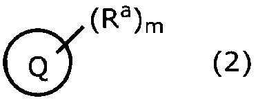
- 前記金属錯体において、[第一の配位子]:[第三の配位子]で表されるmol比が、100:0~5:95の範囲である、請求項1~7のうちのいずれか一項に記載の飽和炭化水素の吸着方法。
- 前記金属錯体が、
下記式(3)で表される第一の配位子Aと、
2原子以上4原子以下のヘテロ原子を含み、かつ、二重結合を含まない複素環式化合物である第二の配位子Bと、
下記式(4)で表される第三の配位子Cと、
クロム、マンガン、鉄、コバルト、ニッケル、銅及び亜鉛からなる群から選択される少なくとも一つの金属のイオンと、
を含む金属錯体である、請求項1~8のうちのいずれか一項に記載の飽和炭化水素の吸着方法。
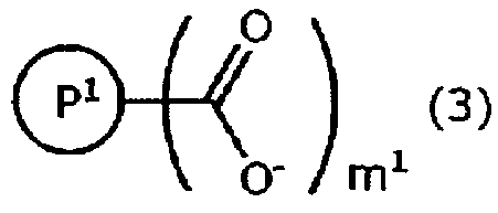

- 請求項1~9のうちのいずれか一項に記載の飽和炭化水素の吸着方法を利用して前記飽和炭化水素と前記不飽和炭化水素とを分離する工程を有する、炭化水素の分離方法。
- 前記金属錯体に、第1の所定圧力の下で前記混合物を接触せしめ、前記飽和炭化水素を前記金属錯体に選択的に吸着させる吸着工程と、
前記吸着工程の後に、圧力を第2の所定圧力に変化させ、前記金属錯体に吸着している前記飽和炭化水素を脱離させる脱離工程と
を含む、請求項10に記載の炭化水素の分離方法。 - 下記式(1)で表される配位子と金属イオンとを含む金属錯体を備える分離手段と、
前記分離手段に炭素数が3以下の飽和炭化水素と不飽和炭化水素とを含む混合物を導入する導入手段と
を備えており、
前記金属錯体に、前記混合物を接触せしめることにより前記飽和炭化水素を前記金属錯体に選択的に吸着させ、前記飽和炭化水素と前記不飽和炭化水素とを分離する、
炭化水素の分離装置。
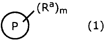
Applications Claiming Priority (2)
| Application Number | Priority Date | Filing Date | Title |
|---|---|---|---|
| JP2013-154993 | 2013-07-25 | ||
| JP2013154993 | 2013-07-25 |
Publications (1)
| Publication Number | Publication Date |
|---|---|
| WO2015012263A1 true WO2015012263A1 (ja) | 2015-01-29 |
Family
ID=52393298
Family Applications (1)
| Application Number | Title | Priority Date | Filing Date |
|---|---|---|---|
| PCT/JP2014/069315 Ceased WO2015012263A1 (ja) | 2013-07-25 | 2014-07-22 | 炭素数3以下の飽和炭化水素の吸着方法、分離方法、及び分離装置 |
Country Status (1)
| Country | Link |
|---|---|
| WO (1) | WO2015012263A1 (ja) |
Citations (6)
| Publication number | Priority date | Publication date | Assignee | Title |
|---|---|---|---|---|
| JPH09323016A (ja) * | 1996-06-07 | 1997-12-16 | Osaka Gas Co Ltd | ガス分離方法、ガス分離装置及びガス分離材 |
| JP2008178853A (ja) * | 2006-12-26 | 2008-08-07 | Nissan Motor Co Ltd | 炭化水素の脱水素触媒及び廃熱回収システム |
| JP2011524870A (ja) * | 2008-06-11 | 2011-09-08 | サントゥル ナシオナル ドゥ ラ ルシェルシュ シアンティ フィック セーエヌエールエス | 異なる不飽和度および/または不飽和数を有している複数の分子の混合物を分離するための、還元可能な多孔質の結晶の固体の混成物 |
| JP2011528687A (ja) * | 2008-07-21 | 2011-11-24 | ビーエーエスエフ ソシエタス・ヨーロピア | プロペンの工業的獲得法 |
| JP2013063951A (ja) * | 2011-08-26 | 2013-04-11 | Sumitomo Chemical Co Ltd | 不飽和炭化水素と飽和炭化水素との分離方法及び分離装置、並びに金属錯体 |
| WO2013069721A1 (ja) * | 2011-11-08 | 2013-05-16 | 株式会社クラレ | 金属錯体、並びにそれからなる吸着材、吸蔵材及び分離材 |
-
2014
- 2014-07-22 WO PCT/JP2014/069315 patent/WO2015012263A1/ja not_active Ceased
Patent Citations (6)
| Publication number | Priority date | Publication date | Assignee | Title |
|---|---|---|---|---|
| JPH09323016A (ja) * | 1996-06-07 | 1997-12-16 | Osaka Gas Co Ltd | ガス分離方法、ガス分離装置及びガス分離材 |
| JP2008178853A (ja) * | 2006-12-26 | 2008-08-07 | Nissan Motor Co Ltd | 炭化水素の脱水素触媒及び廃熱回収システム |
| JP2011524870A (ja) * | 2008-06-11 | 2011-09-08 | サントゥル ナシオナル ドゥ ラ ルシェルシュ シアンティ フィック セーエヌエールエス | 異なる不飽和度および/または不飽和数を有している複数の分子の混合物を分離するための、還元可能な多孔質の結晶の固体の混成物 |
| JP2011528687A (ja) * | 2008-07-21 | 2011-11-24 | ビーエーエスエフ ソシエタス・ヨーロピア | プロペンの工業的獲得法 |
| JP2013063951A (ja) * | 2011-08-26 | 2013-04-11 | Sumitomo Chemical Co Ltd | 不飽和炭化水素と飽和炭化水素との分離方法及び分離装置、並びに金属錯体 |
| WO2013069721A1 (ja) * | 2011-11-08 | 2013-05-16 | 株式会社クラレ | 金属錯体、並びにそれからなる吸着材、吸蔵材及び分離材 |
Non-Patent Citations (5)
Similar Documents
| Publication | Publication Date | Title |
|---|---|---|
| Vo et al. | Highly CO selective Cu (I)-doped MIL-100 (Fe) adsorbent with high CO/CO2 selectivity due to π complexation: Effects of Cu (I) loading and activation temperature | |
| Gutiérrez et al. | Deep eutectic solvents as both precursors and structure directing agents in the synthesis of nitrogen doped hierarchical carbons highly suitable for CO 2 capture | |
| Peng et al. | Efficient kinetic separation of propene and propane using two microporous metal organic frameworks | |
| Qian et al. | A novel anion-pillared metal–organic framework for highly efficient separation of acetylene from ethylene and carbon dioxide | |
| Yoon et al. | Highly selective adsorption of CO over CO2 in a Cu (I)-chelated porous organic polymer | |
| Huang et al. | Preparation and adsorption performance of GrO@ Cu-BTC for separation of CO2/CH4 | |
| Zhang et al. | A new honeycomb MOF for C 2 H 4 purification and C 3 H 6 enrichment by separating methanol to olefin products | |
| Khoshhal et al. | Study of the temperature and solvent content effects on the structure of Cu–BTC metal organic framework for hydrogen storage | |
| Vo et al. | A novel approach to prepare Cu (I) Zn@ MIL-100 (Fe) adsorbent with high CO adsorption capacity, CO/CO2 selectivity and stability via controlled host–guest redox reaction | |
| Vismara et al. | Amino-decorated bis (pyrazolate) metal–organic frameworks for carbon dioxide capture and green conversion into cyclic carbonates | |
| EP2325160B1 (en) | Metal complex and manufacturing method therefor | |
| CN114452938B (zh) | 一种烷烃优先吸附微孔材料及其制备方法和应用 | |
| Cheplakova et al. | Metal–organic frameworks based on octafluorobiphenyl-4, 4′-dicarboxylate: synthesis, crystal structure, and surface functionality | |
| JP2003342260A (ja) | 三次元型金属錯体、吸着材および分離材 | |
| Wang et al. | Novel hexaazatrinaphthalene-based covalent triazine frameworks as high-performance platforms for efficient carbon capture and storage | |
| Song et al. | Merging open metal sites and Lewis basic sites in a NbO-type metal–organic framework for improved C 2 H 2/CH 4 and CO 2/CH 4 separation | |
| Wan et al. | Hydrothermal synthesis of nitrogen-doped ordered mesoporous carbon via lysine-assisted self-assembly for efficient CO 2 capture | |
| Guo et al. | A pillared-layer metal–organic framework for efficient separation of C3H8/C2H6/CH4 in natural gas | |
| CN104395268B (zh) | 1,3-丁二烯分离材及使用该分离材的分离方法 | |
| JP2012031161A (ja) | 金属錯体、並びにそれからなる吸蔵材及び分離材 | |
| JP5478121B2 (ja) | 金属錯体及びその製造方法 | |
| CN111777769A (zh) | 一种用于高效分离混合气体的金属有机框架材料及其制法与应用 | |
| Liu et al. | Linker micro-regulation of a Hofmann-based metal–organic framework for efficient propylene/propane separation | |
| JP2013216622A (ja) | 金属錯体、該金属錯体の製造方法および吸着材 | |
| Lu et al. | A scalable pillar layered metal-organic framework for natural gas purification |
Legal Events
| Date | Code | Title | Description |
|---|---|---|---|
| 121 | Ep: the epo has been informed by wipo that ep was designated in this application |
Ref document number: 14829489 Country of ref document: EP Kind code of ref document: A1 |
|
| NENP | Non-entry into the national phase |
Ref country code: DE |
|
| NENP | Non-entry into the national phase |
Ref country code: JP |
|
| 122 | Ep: pct application non-entry in european phase |
Ref document number: 14829489 Country of ref document: EP Kind code of ref document: A1 |