WO2015012150A1 - マニピュレータシステム - Google Patents
マニピュレータシステム Download PDFInfo
- Publication number
- WO2015012150A1 WO2015012150A1 PCT/JP2014/068754 JP2014068754W WO2015012150A1 WO 2015012150 A1 WO2015012150 A1 WO 2015012150A1 JP 2014068754 W JP2014068754 W JP 2014068754W WO 2015012150 A1 WO2015012150 A1 WO 2015012150A1
- Authority
- WO
- WIPO (PCT)
- Prior art keywords
- treatment instrument
- unit
- bending
- compensation value
- channel
- Prior art date
- Legal status (The legal status is an assumption and is not a legal conclusion. Google has not performed a legal analysis and makes no representation as to the accuracy of the status listed.)
- Ceased
Links
Images


Classifications
-
- A—HUMAN NECESSITIES
- A61—MEDICAL OR VETERINARY SCIENCE; HYGIENE
- A61B—DIAGNOSIS; SURGERY; IDENTIFICATION
- A61B1/00—Instruments for performing medical examinations of the interior of cavities or tubes of the body by visual or photographical inspection, e.g. endoscopes; Illuminating arrangements therefor
- A61B1/00147—Holding or positioning arrangements
- A61B1/0016—Holding or positioning arrangements using motor drive units
-
- A—HUMAN NECESSITIES
- A61—MEDICAL OR VETERINARY SCIENCE; HYGIENE
- A61B—DIAGNOSIS; SURGERY; IDENTIFICATION
- A61B1/00—Instruments for performing medical examinations of the interior of cavities or tubes of the body by visual or photographical inspection, e.g. endoscopes; Illuminating arrangements therefor
- A61B1/00002—Operational features of endoscopes
- A61B1/00004—Operational features of endoscopes characterised by electronic signal processing
- A61B1/00006—Operational features of endoscopes characterised by electronic signal processing of control signals
-
- A—HUMAN NECESSITIES
- A61—MEDICAL OR VETERINARY SCIENCE; HYGIENE
- A61B—DIAGNOSIS; SURGERY; IDENTIFICATION
- A61B1/00—Instruments for performing medical examinations of the interior of cavities or tubes of the body by visual or photographical inspection, e.g. endoscopes; Illuminating arrangements therefor
- A61B1/00002—Operational features of endoscopes
- A61B1/00039—Operational features of endoscopes provided with input arrangements for the user
- A61B1/00042—Operational features of endoscopes provided with input arrangements for the user for mechanical operation
-
- A—HUMAN NECESSITIES
- A61—MEDICAL OR VETERINARY SCIENCE; HYGIENE
- A61B—DIAGNOSIS; SURGERY; IDENTIFICATION
- A61B1/00—Instruments for performing medical examinations of the interior of cavities or tubes of the body by visual or photographical inspection, e.g. endoscopes; Illuminating arrangements therefor
- A61B1/00002—Operational features of endoscopes
- A61B1/00057—Operational features of endoscopes provided with means for testing or calibration
-
- A—HUMAN NECESSITIES
- A61—MEDICAL OR VETERINARY SCIENCE; HYGIENE
- A61B—DIAGNOSIS; SURGERY; IDENTIFICATION
- A61B1/00—Instruments for performing medical examinations of the interior of cavities or tubes of the body by visual or photographical inspection, e.g. endoscopes; Illuminating arrangements therefor
- A61B1/00131—Accessories for endoscopes
- A61B1/00133—Drive units for endoscopic tools inserted through or with the endoscope
-
- A—HUMAN NECESSITIES
- A61—MEDICAL OR VETERINARY SCIENCE; HYGIENE
- A61B—DIAGNOSIS; SURGERY; IDENTIFICATION
- A61B1/00—Instruments for performing medical examinations of the interior of cavities or tubes of the body by visual or photographical inspection, e.g. endoscopes; Illuminating arrangements therefor
- A61B1/00131—Accessories for endoscopes
- A61B1/00135—Oversleeves mounted on the endoscope prior to insertion
-
- A—HUMAN NECESSITIES
- A61—MEDICAL OR VETERINARY SCIENCE; HYGIENE
- A61B—DIAGNOSIS; SURGERY; IDENTIFICATION
- A61B1/00—Instruments for performing medical examinations of the interior of cavities or tubes of the body by visual or photographical inspection, e.g. endoscopes; Illuminating arrangements therefor
- A61B1/00147—Holding or positioning arrangements
- A61B1/00149—Holding or positioning arrangements using articulated arms
-
- A—HUMAN NECESSITIES
- A61—MEDICAL OR VETERINARY SCIENCE; HYGIENE
- A61B—DIAGNOSIS; SURGERY; IDENTIFICATION
- A61B1/00—Instruments for performing medical examinations of the interior of cavities or tubes of the body by visual or photographical inspection, e.g. endoscopes; Illuminating arrangements therefor
- A61B1/005—Flexible endoscopes
- A61B1/0051—Flexible endoscopes with controlled bending of insertion part
-
- A—HUMAN NECESSITIES
- A61—MEDICAL OR VETERINARY SCIENCE; HYGIENE
- A61B—DIAGNOSIS; SURGERY; IDENTIFICATION
- A61B1/00—Instruments for performing medical examinations of the interior of cavities or tubes of the body by visual or photographical inspection, e.g. endoscopes; Illuminating arrangements therefor
- A61B1/005—Flexible endoscopes
- A61B1/009—Flexible endoscopes with bending or curvature detection of the insertion part
-
- A—HUMAN NECESSITIES
- A61—MEDICAL OR VETERINARY SCIENCE; HYGIENE
- A61B—DIAGNOSIS; SURGERY; IDENTIFICATION
- A61B34/00—Computer-aided surgery; Manipulators or robots specially adapted for use in surgery
- A61B34/30—Surgical robots
-
- A—HUMAN NECESSITIES
- A61—MEDICAL OR VETERINARY SCIENCE; HYGIENE
- A61B—DIAGNOSIS; SURGERY; IDENTIFICATION
- A61B34/00—Computer-aided surgery; Manipulators or robots specially adapted for use in surgery
- A61B34/30—Surgical robots
- A61B34/37—Leader-follower robots
-
- A—HUMAN NECESSITIES
- A61—MEDICAL OR VETERINARY SCIENCE; HYGIENE
- A61B—DIAGNOSIS; SURGERY; IDENTIFICATION
- A61B90/00—Instruments, implements or accessories specially adapted for surgery or diagnosis and not covered by any of the groups A61B1/00 - A61B50/00, e.g. for luxation treatment or for protecting wound edges
- A61B90/90—Identification means for patients or instruments, e.g. tags
- A61B90/94—Identification means for patients or instruments, e.g. tags coded with symbols, e.g. text
- A61B90/96—Identification means for patients or instruments, e.g. tags coded with symbols, e.g. text using barcodes
-
- A—HUMAN NECESSITIES
- A61—MEDICAL OR VETERINARY SCIENCE; HYGIENE
- A61B—DIAGNOSIS; SURGERY; IDENTIFICATION
- A61B90/00—Instruments, implements or accessories specially adapted for surgery or diagnosis and not covered by any of the groups A61B1/00 - A61B50/00, e.g. for luxation treatment or for protecting wound edges
- A61B90/90—Identification means for patients or instruments, e.g. tags
- A61B90/98—Identification means for patients or instruments, e.g. tags using electromagnetic means, e.g. transponders
-
- B—PERFORMING OPERATIONS; TRANSPORTING
- B25—HAND TOOLS; PORTABLE POWER-DRIVEN TOOLS; MANIPULATORS
- B25J—MANIPULATORS; CHAMBERS PROVIDED WITH MANIPULATION DEVICES
- B25J18/00—Arms
- B25J18/06—Arms flexible
-
- B—PERFORMING OPERATIONS; TRANSPORTING
- B25—HAND TOOLS; PORTABLE POWER-DRIVEN TOOLS; MANIPULATORS
- B25J—MANIPULATORS; CHAMBERS PROVIDED WITH MANIPULATION DEVICES
- B25J9/00—Program-controlled manipulators
- B25J9/16—Program controls
- B25J9/1679—Program controls characterised by the tasks executed
- B25J9/1689—Teleoperation
-
- A—HUMAN NECESSITIES
- A61—MEDICAL OR VETERINARY SCIENCE; HYGIENE
- A61B—DIAGNOSIS; SURGERY; IDENTIFICATION
- A61B34/00—Computer-aided surgery; Manipulators or robots specially adapted for use in surgery
- A61B34/30—Surgical robots
- A61B2034/301—Surgical robots for introducing or steering flexible instruments inserted into the body, e.g. catheters or endoscopes
Definitions
- the present invention relates to an elongated insertion portion having a plurality of channels penetrating in the longitudinal direction, a treatment instrument inserted into the channel of the insertion portion, and at least of the advancement / retraction and rotation of the treatment instrument within the channel
- a manipulator having a treatment instrument drive section for performing one operation; an operation input section for inputting an operation instruction to the treatment instrument by an operator; and the treatment instrument drive according to the operation instruction input to the operation input section
- a control unit that generates a control signal for driving the unit, a use channel detection unit that detects a channel in which the treatment instrument is inserted among the plurality of channels, and a channel detected by the use channel detection unit
- a compensation value setting unit that sets a compensation value for the control signal based on the control signal, and the control unit sets the control signal to the compensation value setting. Using the set the compensation value to correct by providing a manipulator system for transmitting a corrected said control signal to said surgical instrument drive unit.
- a treatment instrument identification unit that identifies the treatment instrument inserted in each channel
- the compensation value setting unit has a mechanical characteristic of the treatment instrument identified by the treatment instrument identification unit.
- each compensation value may be set based on the above. By doing so, the responsiveness of the treatment tool also depends on the mechanical characteristics of the treatment tool. Therefore, by reflecting the mechanical characteristics of the treatment instrument in the compensation value, it is possible to compensate for the reduction and variation in the responsiveness of the treatment instrument with higher accuracy.
- control unit performs feedforward control or feedback control on the treatment instrument drive unit
- compensation value setting unit uses a gain used by the control unit for the feedforward control or feedback control as the compensation value. Also good. By doing so, it is possible to compensate for a decrease and variation in the response of the bending portion using a simple control method.
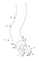
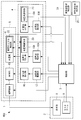
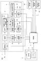
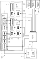
- the slave manipulator 1 includes a slave arm 4 disposed in the vicinity of an operating table 80 on which a patient P lies, an insertion portion 5 held at the distal end of the slave arm 4, and a treatment tool 6 inserted into the insertion portion 5. And. As shown in FIG. 2, an observation member 7 is provided at the distal end of the insertion portion 5, and the treatment tool 6 protruding from the visual field in front of the distal end of the insertion portion 5 and the distal end of the insertion portion 5 by the observation member 7. And is to be taken. The video acquired by the observation member 7 is displayed on the display unit 8 provided in the master input unit 2.
- Two attachment portions 11A and 11B and two treatment instrument drive portions 13A and 13B are provided.
- the two treatment instrument attachment portions 11A and 11B are collectively referred to as a treatment instrument attachment portion 11.
- the two treatment instrument drive units 13A and 13B are also collectively referred to as a treatment instrument drive unit 13.
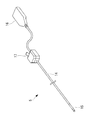
- the base end portions of the wires 15a and 15b are drawn from the base end of the flexible portion 14 and wound around a pulley 16a provided in the mounting unit 16, as shown in FIG.
- the attachment unit 16 is configured such that, when attached to the insertion portion attachment portion 10, each pulley 16 a and each motor 12 a included in the bending portion driving portion 12 are coaxially connected.
- the motor 12a rotates according to the bending control signal from the control unit 3
- the pulley 16a rotates forward or reverse, and the wires 15a and 15b are pushed and pulled to change the bending angle of the bending unit 15.
- Yes. 5 in order to simplify the drawing, only one motor 12a is shown, and only two wires 15a and 15b are wound around two pulleys 16 on the flexible part 14 side. ing.
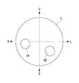
- the control unit 3 recognizes the channels 5A and 5B in which the treatment tool 6 is inserted based on the identification information of the channels 5A and 5B received from the used channel detection unit 22, and the FF corresponding to the recognized channels 5A and 5B. Select the gains K 1 and K 2 .
- the control unit 3 amplifies the advance / retreat control signal and the rotation control signal by multiplying the advance / retreat control signal and the rotation control signal generated from the operation signal by the FF gains K 1 and K 2 , respectively.
- the treatment instrument drive units 13A and 13B are feedforward controlled.
- the linear motion and the rotational motion applied to the proximal end portion of the main body 18 by the motors 13a and 13b are caused by friction generated between the treatment instrument 6 and the inner surfaces of the channels 5A and 5B, and the main body 18 in the channels 5A and 5B. Due to slackness or the like, it attenuates during transmission to the tip of the main body 18. As a result, the actual advance / retreat amount and rotation amount of the treatment section 19 are reduced with respect to the outputs of the motors 13a, 13b.
- the friction and slack vary depending on the inner diameter and inner material of the channels 5A and 5B. As a result, even if the same treatment tool 6 is used, the responsiveness of the operation of the treatment tool 6 varies depending on which channel 5A, 5B is used.
- the compensation value may be a friction compensation coefficient (offset signal) that the control unit 3 adds to these control signals in order to give an offset to the advance / retreat control signal and the rotation control signal.
- the friction compensation coefficient is set so that the sign is reversed at the folded portion where the direction of the operation of the treatment instrument 6 is switched in the reverse direction. Thereby, it is possible to reduce backlash that occurs particularly when the direction of operation is switched in the reverse direction (for example, when switching from left rotation to right rotation).
- control unit 3 recognizes that the first treatment instrument 6 has been inserted into the first channel 5A.
- Control unit 3 selects the FF gain K 1 that is set for the combination of the first channel 5A and the first treatment tool 6. Thereafter, when the operation to the treatment instrument 6 to the master arm 9 is input, the control unit 3, forward and backward control signal and the rotation control signal by multiplying the FF gain K 1, the treatment instrument drive unit these control signals amplified To 13A.
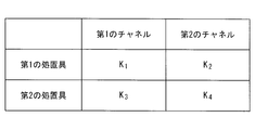
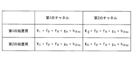
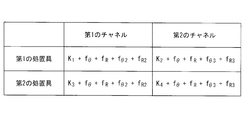
- the responsiveness of the operation of the treatment instrument 6 described above also varies depending on the combination of the channels 5A and 5B and the treatment instrument 6. That is, the friction generated between the treatment tool 6 and the inner surfaces of the channels 5A and 5B varies depending on the combination of the inner diameter and inner surface material of the channels 5A and 5B and the outer shape and material of the treatment tool 6. Furthermore, responsiveness differs for every treatment tool 6 according to mechanical characteristics, such as rigidity, which the main body 18 of the treatment tool 6 has. As a result, even if the channels 5A and 5B to be used are the same, if the treatment tools 6 inserted into the channels 5A and 5B are different, the responsiveness of the operation differs for each treatment tool 6.
- the FF gains K 1 , K 2 , K 3 , and K 4 are further set in accordance with the combination of the channels 5A and 5B and the treatment tool 6, thereby allowing the channels 5A and 5B to be treated. Variations in the responsiveness of the operation of different treatment tools 6 depending on the combination with the tool 6 are further compensated. Accordingly, there is an advantage that it is possible to always obtain good and the same responsiveness of the advance / retreat operation and the rotation operation of the treatment tool 6 regardless of which treatment tool 6 is used in any channel 5A, 5B.
- each wire 15a, 15b extends in parallel to each wire 15a, 15b to the proximal end side of the flexible portion 14, and includes a wire rod that is movable along with each wire 15a, 15b.
- the actual bending angle of the bending portion 15 may be detected based on the amount of movement of the wire.
- the wire corresponds to the sensor.
- the bending radius R (R1, R2) of each channel 5A, 5B is different between when the bending portion 15 is bent to the left side and when the bending portion 15 is bent to the right side.
- the function f ⁇ may be set for each bending direction of the bending portion 15, and the FF gain shown in FIG. 11 may be modified as the following equation.
- K is K 1 , K 2 , K 3 or K 4 .
- FF gain (left side) K + f ⁇ _LEFT + f R
- FF gain (right side) K + f ⁇ _RIGHT + f R
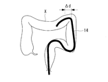
- the soft part shape detection unit 25 calculates a feature amount k indicating the entire bending amount of the soft part 14 according to the following procedure from the curved shape of the soft part 14 acquired by the endoscope insertion shape observation device.
- the soft part shape detection unit 25 divides the soft part 14 into minute sections ⁇ d in the longitudinal direction, and measures the bending radius r and the bending angle ⁇ for each minute section ⁇ d. To do.
- the soft part shape detection unit 25 holds a function that defines the relationship between the feature amount ⁇ k of the minute section ⁇ d, the bending radius r, and the bending angle ⁇ .
- the tubes constituting the channels 5 ⁇ / b> A and 5 ⁇ / b> B have a fixed radial position in the insertion portion 5. If the tube is movable in the radial direction inside the flexible portion 14 and the bending portion 15, even if the bending shapes of the flexible portion 14 and the bending portion 15 are the same, the optimum compensation value may be different. There is. This is because the friction and looseness generated in the main body 18 of the treatment instrument 6 may vary due to variations in the tube path.
- the positions of the treatment tool attachment portions 11A and 11B to which the attachment unit 20 is attached are different, and the routing shape of the treatment tool 6 for the outside of the body is different. Further, the routing shape differs for each treatment instrument 6 depending on the rigidity and length of the main body 18.
- the drawing shape for the external body is almost constant for each combination of the treatment instrument attachment portions 11A and 11B and the treatment instrument 6. Therefore, by measuring the bending angle ⁇ ex of the external body of each treatment instrument 6 when the attachment unit 20 is attached to each treatment instrument attachment section 11A, 11B, the treatment instrument 6 and the treatment instrument attachment sections 11A, 11B, A table in which the bending angle ⁇ ex is associated is acquired in advance.
- the extracorporeal part shape detection unit 26 can detect the bending angle ⁇ ex by referring to the table based on the identification information between the channels 5A and 5B and the treatment instrument 6 described above.
- the manipulator system 500 configured as described above will be described.
- the basic procedure is the same as in the first embodiment.
- the manipulator system 400 according to the present embodiment is different from the first to fourth embodiments in the method of setting the FF gain.
- variation in the responsiveness of the treatment tool 6 mentioned above further depends on the curved shape for the external part of the treatment tool 6.
- the FF gain K i + f ⁇ + f R + g k + h ⁇ ex further by setting even depending on the bending angle theta ex extracorporeal part, due to the difference of bending angle theta ex extracorporeal portion Variations in the responsiveness of the operation of the treatment instrument 6 to be performed are further compensated.
Landscapes
- Health & Medical Sciences (AREA)
- Life Sciences & Earth Sciences (AREA)
- Surgery (AREA)
- Engineering & Computer Science (AREA)
- Veterinary Medicine (AREA)
- Public Health (AREA)
- General Health & Medical Sciences (AREA)
- Animal Behavior & Ethology (AREA)
- Nuclear Medicine, Radiotherapy & Molecular Imaging (AREA)
- Molecular Biology (AREA)
- Biomedical Technology (AREA)
- Heart & Thoracic Surgery (AREA)
- Medical Informatics (AREA)
- Pathology (AREA)
- Physics & Mathematics (AREA)
- Radiology & Medical Imaging (AREA)
- Optics & Photonics (AREA)
- Biophysics (AREA)
- Robotics (AREA)
- Mechanical Engineering (AREA)
- Oral & Maxillofacial Surgery (AREA)
- Signal Processing (AREA)
- Electromagnetism (AREA)
- Manipulator (AREA)
- Endoscopes (AREA)
Priority Applications (3)
| Application Number | Priority Date | Filing Date | Title |
|---|---|---|---|
| CN201480041043.2A CN105392442B (zh) | 2013-07-26 | 2014-07-15 | 机械手系统 |
| EP14830359.7A EP3025675B1 (en) | 2013-07-26 | 2014-07-15 | Manipulator system |
| US15/001,509 US20160135662A1 (en) | 2013-07-26 | 2016-01-20 | Manipulator system |
Applications Claiming Priority (2)
| Application Number | Priority Date | Filing Date | Title |
|---|---|---|---|
| JP2013-155882 | 2013-07-26 | ||
| JP2013155882A JP6027947B2 (ja) | 2013-07-26 | 2013-07-26 | マニピュレータシステム |
Related Child Applications (1)
| Application Number | Title | Priority Date | Filing Date |
|---|---|---|---|
| US15/001,509 Continuation US20160135662A1 (en) | 2013-07-26 | 2016-01-20 | Manipulator system |
Publications (1)
| Publication Number | Publication Date |
|---|---|
| WO2015012150A1 true WO2015012150A1 (ja) | 2015-01-29 |
Family
ID=52393194
Family Applications (1)
| Application Number | Title | Priority Date | Filing Date |
|---|---|---|---|
| PCT/JP2014/068754 Ceased WO2015012150A1 (ja) | 2013-07-26 | 2014-07-15 | マニピュレータシステム |
Country Status (5)
| Country | Link |
|---|---|
| US (1) | US20160135662A1 (https=) |
| EP (1) | EP3025675B1 (https=) |
| JP (1) | JP6027947B2 (https=) |
| CN (1) | CN105392442B (https=) |
| WO (1) | WO2015012150A1 (https=) |
Cited By (1)
| Publication number | Priority date | Publication date | Assignee | Title |
|---|---|---|---|---|
| WO2017006377A1 (ja) * | 2015-07-09 | 2017-01-12 | 川崎重工業株式会社 | 手術用ロボット |
Families Citing this family (13)
| Publication number | Priority date | Publication date | Assignee | Title |
|---|---|---|---|---|
| JP6271027B2 (ja) * | 2015-02-26 | 2018-01-31 | オリンパス株式会社 | オーバーチューブおよび医療用マニピュレータシステム |
| US10939804B2 (en) | 2015-03-19 | 2021-03-09 | Endomaster Pte Ltd | Enhanced flexible robotic endoscopy apparatus |
| CN107529939B (zh) | 2015-04-07 | 2019-08-27 | 奥林巴斯株式会社 | 插拔装置、插入部的直接操作推测方法及非暂时性存储插入部的直接操作推测程序的存储介质 |
| US11013567B2 (en) | 2016-03-17 | 2021-05-25 | Intuitive Surgical Operations, Inc. | Systems and methods for instrument insertion control |
| JP6715949B2 (ja) * | 2016-12-05 | 2020-07-01 | オリンパス株式会社 | 軟性マニピュレータ |
| WO2018122993A1 (ja) | 2016-12-28 | 2018-07-05 | オリンパス株式会社 | 医療システム、医療用オーバーチューブ、及び医療デバイスアダプタ |
| US10426559B2 (en) * | 2017-06-30 | 2019-10-01 | Auris Health, Inc. | Systems and methods for medical instrument compression compensation |
| WO2019207674A1 (ja) * | 2018-04-25 | 2019-10-31 | オリンパス株式会社 | 駆動装置および医療用マニピュレータ |
| US11426059B2 (en) * | 2018-06-02 | 2022-08-30 | Ankon Medical Technologies (Shanghai) Co., Ltd. | Control system for capsule endoscope |
| GB2614476B (en) * | 2020-11-17 | 2025-02-26 | Prec Robotics Hong Kong Limited | Feeding device for tubular component |
| CN118986526A (zh) | 2021-02-17 | 2024-11-22 | 奥瑞斯健康公司 | 器械轴张紧系统和方法 |
| KR20240113752A (ko) * | 2021-09-27 | 2024-07-23 | 사이트렐리스 바이오시스템즈, 인크. | 피부 치료 시스템, 디바이스, 및 방법 |
| CN116077195A (zh) * | 2023-01-13 | 2023-05-09 | 深圳市爱博医疗机器人有限公司 | 一种柔性医疗器械递送系统 |
Citations (4)
| Publication number | Priority date | Publication date | Assignee | Title |
|---|---|---|---|---|
| JP2007089808A (ja) | 2005-09-28 | 2007-04-12 | Olympus Medical Systems Corp | 内視鏡システム |
| JP2008245840A (ja) * | 2007-03-29 | 2008-10-16 | Olympus Medical Systems Corp | 内視鏡装置 |
| JP2009000500A (ja) * | 2007-06-22 | 2009-01-08 | Olympus Medical Systems Corp | 医療装置 |
| JP2010214128A (ja) * | 2010-05-19 | 2010-09-30 | Olympus Medical Systems Corp | 処置具システム及びマニピュレータシステム |
Family Cites Families (12)
| Publication number | Priority date | Publication date | Assignee | Title |
|---|---|---|---|---|
| US10820949B2 (en) * | 1999-04-07 | 2020-11-03 | Intuitive Surgical Operations, Inc. | Medical robotic system with dynamically adjustable slave manipulator characteristics |
| JP3973504B2 (ja) * | 2002-07-15 | 2007-09-12 | 株式会社日立製作所 | 牽引位置決め装置 |
| US8753262B2 (en) * | 2003-07-29 | 2014-06-17 | Hoya Corporation | Internal treatment apparatus having circumferential side holes |
| JP4694280B2 (ja) * | 2005-06-16 | 2011-06-08 | Hoya株式会社 | 電子内視鏡用光源装置及び電子内視鏡装置 |
| US7918783B2 (en) * | 2006-03-22 | 2011-04-05 | Boston Scientific Scimed, Inc. | Endoscope working channel with multiple functionality |
| US9089256B2 (en) * | 2008-06-27 | 2015-07-28 | Intuitive Surgical Operations, Inc. | Medical robotic system providing an auxiliary view including range of motion limitations for articulatable instruments extending out of a distal end of an entry guide |
| JP4580973B2 (ja) * | 2007-11-29 | 2010-11-17 | オリンパスメディカルシステムズ株式会社 | 処置具システム |
| JP5295555B2 (ja) * | 2007-12-10 | 2013-09-18 | オリンパスメディカルシステムズ株式会社 | 内視鏡システム |
| JP4672031B2 (ja) * | 2008-01-31 | 2011-04-20 | オリンパスメディカルシステムズ株式会社 | 医療器具 |
| CN102770060B (zh) * | 2010-03-17 | 2015-03-25 | 奥林巴斯医疗株式会社 | 内窥镜系统 |
| JP5973727B2 (ja) * | 2011-12-28 | 2016-08-23 | オリンパス株式会社 | 立体内視鏡装置、立体内視鏡システムおよび立体内視鏡ロボット |
| JP6116426B2 (ja) * | 2013-07-25 | 2017-04-19 | オリンパス株式会社 | マニピュレータシステム |
-
2013
- 2013-07-26 JP JP2013155882A patent/JP6027947B2/ja active Active
-
2014
- 2014-07-15 CN CN201480041043.2A patent/CN105392442B/zh active Active
- 2014-07-15 WO PCT/JP2014/068754 patent/WO2015012150A1/ja not_active Ceased
- 2014-07-15 EP EP14830359.7A patent/EP3025675B1/en active Active
-
2016
- 2016-01-20 US US15/001,509 patent/US20160135662A1/en not_active Abandoned
Patent Citations (4)
| Publication number | Priority date | Publication date | Assignee | Title |
|---|---|---|---|---|
| JP2007089808A (ja) | 2005-09-28 | 2007-04-12 | Olympus Medical Systems Corp | 内視鏡システム |
| JP2008245840A (ja) * | 2007-03-29 | 2008-10-16 | Olympus Medical Systems Corp | 内視鏡装置 |
| JP2009000500A (ja) * | 2007-06-22 | 2009-01-08 | Olympus Medical Systems Corp | 医療装置 |
| JP2010214128A (ja) * | 2010-05-19 | 2010-09-30 | Olympus Medical Systems Corp | 処置具システム及びマニピュレータシステム |
Cited By (3)
| Publication number | Priority date | Publication date | Assignee | Title |
|---|---|---|---|---|
| WO2017006377A1 (ja) * | 2015-07-09 | 2017-01-12 | 川崎重工業株式会社 | 手術用ロボット |
| JPWO2017006377A1 (ja) * | 2015-07-09 | 2018-05-24 | 川崎重工業株式会社 | 手術用ロボット |
| US11198226B2 (en) | 2015-07-09 | 2021-12-14 | Kawasaki Jukogyo Kabushiki Kaisha | Surgical robot |
Also Published As
| Publication number | Publication date |
|---|---|
| JP2015024033A (ja) | 2015-02-05 |
| CN105392442A (zh) | 2016-03-09 |
| US20160135662A1 (en) | 2016-05-19 |
| EP3025675A4 (en) | 2017-05-17 |
| JP6027947B2 (ja) | 2016-11-16 |
| EP3025675A1 (en) | 2016-06-01 |
| CN105392442B (zh) | 2017-11-28 |
| EP3025675B1 (en) | 2018-10-03 |
Similar Documents
| Publication | Publication Date | Title |
|---|---|---|
| JP6027947B2 (ja) | マニピュレータシステム | |
| JP6116426B2 (ja) | マニピュレータシステム | |
| US12539400B2 (en) | Catheter with removable vision probe | |
| US12127797B2 (en) | Catheter sensor systems | |
| JP6037964B2 (ja) | マニピュレータシステム | |
| CN103874525B (zh) | 导管系统 | |
| JP5932172B2 (ja) | 内視鏡システム | |
| JP5443801B2 (ja) | 張力検出手段及びそれを用いたマニピュレータ | |
| JP6329528B2 (ja) | 処置具 | |
| JP2015160278A (ja) | 医療用システム及び処置具のキャリブレーション方法 | |
| EP2873362B1 (en) | Insertion device | |
| WO2019207674A1 (ja) | 駆動装置および医療用マニピュレータ |
Legal Events
| Date | Code | Title | Description |
|---|---|---|---|
| WWE | Wipo information: entry into national phase |
Ref document number: 201480041043.2 Country of ref document: CN |
|
| 121 | Ep: the epo has been informed by wipo that ep was designated in this application |
Ref document number: 14830359 Country of ref document: EP Kind code of ref document: A1 |
|
| NENP | Non-entry into the national phase |
Ref country code: DE |
|
| WWE | Wipo information: entry into national phase |
Ref document number: 2014830359 Country of ref document: EP |