WO2015011817A1 - 医療機器 - Google Patents
医療機器 Download PDFInfo
- Publication number
- WO2015011817A1 WO2015011817A1 PCT/JP2013/070201 JP2013070201W WO2015011817A1 WO 2015011817 A1 WO2015011817 A1 WO 2015011817A1 JP 2013070201 W JP2013070201 W JP 2013070201W WO 2015011817 A1 WO2015011817 A1 WO 2015011817A1
- Authority
- WO
- WIPO (PCT)
- Prior art keywords
- winding
- bending
- operation line
- main body
- unit
- Prior art date
- Legal status (The legal status is an assumption and is not a legal conclusion. Google has not performed a legal analysis and makes no representation as to the accuracy of the status listed.)
- Ceased
Links
Images






Classifications
-
- A—HUMAN NECESSITIES
- A61—MEDICAL OR VETERINARY SCIENCE; HYGIENE
- A61M—DEVICES FOR INTRODUCING MEDIA INTO, OR ONTO, THE BODY; DEVICES FOR TRANSDUCING BODY MEDIA OR FOR TAKING MEDIA FROM THE BODY; DEVICES FOR PRODUCING OR ENDING SLEEP OR STUPOR
- A61M25/00—Catheters; Hollow probes
- A61M25/01—Introducing, guiding, advancing, emplacing or holding catheters
- A61M25/0105—Steering means as part of the catheter or advancing means; Markers for positioning
- A61M25/0133—Tip steering devices
- A61M25/0136—Handles therefor
-
- A—HUMAN NECESSITIES
- A61—MEDICAL OR VETERINARY SCIENCE; HYGIENE
- A61M—DEVICES FOR INTRODUCING MEDIA INTO, OR ONTO, THE BODY; DEVICES FOR TRANSDUCING BODY MEDIA OR FOR TAKING MEDIA FROM THE BODY; DEVICES FOR PRODUCING OR ENDING SLEEP OR STUPOR
- A61M25/00—Catheters; Hollow probes
- A61M25/01—Introducing, guiding, advancing, emplacing or holding catheters
- A61M25/0105—Steering means as part of the catheter or advancing means; Markers for positioning
- A61M25/0133—Tip steering devices
- A61M25/0147—Tip steering devices with movable mechanical means, e.g. pull wires
Definitions
- the present invention relates to a medical device.
- distal end As a typical example, for example, a catheter is known.
- an operation line is fixed to the distal end portion of the catheter, and a control handle for pulling the operation line is provided at the proximal end portion of the catheter (hereinafter referred to as “proximal end portion”)
- proximal end portion A technique for bending an operation line by bending a control handle to bend the distal end portion is described.
- the control handle has a lever structure that is pivotally supported, and the lever structure is provided with a pulley.
- the proximal end portion of the operation line is hung on a pulley and folded back toward the distal end side of the catheter.
- the proximal end of the operation line is connected to a constant force spring provided in the control handle, and is pulled toward the distal end side of the catheter by the constant force spring.
- the pulling operation can be performed by rotating the lever structure around the axis.
- the catheter since the proximal end of the operation line is pulled by a constant force spring, it is considered that the operation line is maintained in a state without sagging.
- the catheter further includes a stop member that prevents the proximal end of the operation line from moving beyond a predetermined position toward the pulley. The stop member is considered to bend the distal end portion reliably by restricting the extension of the constant force spring during the traction operation.
- the present invention has been made in view of the above problems, and provides a medical device such as a catheter capable of adjusting the amount of sag of the operation line in a state where stress is not exerted on the operation line as much as possible.
- the present invention comprises a long and flexible main body, An operation line embedded in the main body and having a tip fixed to the tip of the main body, A hand operation part provided at a base end part of the main body part and connected to a base end part of the operation line; A bending operation unit provided in the hand operation unit for performing an operation of bending the main body unit by pulling the operation line; The amount of slack for performing an operation that is provided in the hand operation unit and that adjusts the amount by which the operation line can be drawn from the hand operation unit without changing the pulling amount of the operation line by the bending operation unit.
- An adjustment operation unit; A medical device is provided.
- the sag amount adjustment for performing the operation of adjusting the amount that the operation line can be drawn from the hand operation unit without changing the pulling amount of the operation line by the bending operation unit is performed on the hand operation unit.
- An operation unit is provided. Therefore, when the traction operation is not executed, the amount of sag of the operation line can be adjusted by adjusting the amount of operation line that can be drawn out from the hand operation unit by operating the sag amount adjustment operation unit.
- a tensile force such as a constant force spring in Patent Document 1 does not act on the operation line. For this reason, it is possible to adjust the amount of sag of the operation line in a state where stress is not applied to the operation line as much as possible.
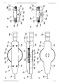
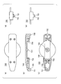
- FIG. 1 It is a figure which shows the hand operation part of the catheter which concerns on 1st Embodiment, Among these, (a) is a top view, (b) is a side view, (c) is a bottom view, (d) is a front view, (e ) Is a rear view. It is a sectional side view which shows the hand operation part of the catheter which concerns on 1st Embodiment. It is a figure which shows the lower case of a hand operation part, (a) is a top view, (b) is a sectional side view, (c) is a bottom view, (d) is a front view, (e) is a rear view. is there.
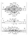
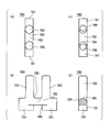
- FIG. 1 It is a figure which shows the upper case of a hand operation part, (a) is a top view, (b) is a sectional side view, (c) is a bottom view, (d) is a front view, (e) is a rear view. is there. It is a figure which shows the state which removed the upper case and the dial operation part (bending winding operation part) from the hand operation part, (a) is a top view, (b) is a side view, (c) is a side cross section FIG. It is a figure which shows the guide part of a hand operation part, among these, (a) is a top view, (b) is a front view, (c) is a bottom view, (d) is a sectional side view.
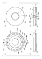
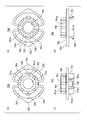
- FIG. 1 It is a figure which shows the winding reel (winding part for bending) of a hand operation part, (a) is a top view, (b) is a bottom view, (c) is a front view, (d) is a side view is there. It is a figure which shows the dial operation part of a hand operation part, among these, (a) is a top view, (b) is a bottom view, (c) is a side view. It is a figure which shows the limiter member of a hand operation part, (a) is a top view, (b) is a bottom view, (c) is a front view, (d) is a side view.
- FIG. 1 It is a figure which shows the sagging amount adjustment operation part of a hand operation part, among these, (a) is a top view, (b) is a front view, (c) is a side view. It is a schematic diagram which shows the path
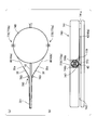
- FIG. It is II-II sectional drawing of FIG. It is a figure which shows the catheter which concerns on embodiment, Among these, (a) shows the state which bent the front-end
- FIG. 1 and 2 are views showing a hand operating portion 70 of the catheter 10 (FIG. 15) according to the first embodiment, in which FIG. 1 (a) is a plan view, FIG. 1 (b) is a side view, 1C is a bottom view, FIG. 1D is a front view, FIG. 1E is a rear view, and FIG. 2 is a side sectional view.
- 3A and 3B are views showing the lower case 710 of the hand operation unit 70, in which (a) is a plan view, (b) is a side sectional view, (c) is a bottom view, (d) is a front view, and (e). ) Is a rear view.
- FIGS. 4A and 4B are views showing the upper case 720 of the hand operating unit 70, in which (a) is a plan view, (b) is a side sectional view, (c) is a bottom view, (d) is a front view, and (e). ) Is a rear view.
- 5A and 5B are views showing a state in which the upper case 720 and the dial operation unit (which constitutes the bending operation unit 730) 760 are removed from the hand operation unit 70, in which (a) is a plan view and (b) is a side view. (C) is a sectional side view.
- FIGS. 6A and 6B are diagrams showing the guide portion 780 of the hand operation unit 70, in which (a) is a plan view, (b) is a front view, (c) is a bottom view, and (d) is a side sectional view.
- 7A and 7B are views showing a take-up reel 740 (which constitutes the bending operation unit 730) of the hand operation unit 70, in which (a) is a plan view, (b) is a bottom view, and (c) is a front view, (D) is a side view.
- FIG. 8 is a diagram showing the dial operation unit 760 of the hand operation unit 70, in which (a) is a plan view, (b) is a bottom view, and (c) is a side view.
- FIG. 9A and 9B are diagrams showing the limiter member 750 of the hand operation unit 70, in which (a) is a plan view, (b) is a bottom view, (c) is a front view, and (d) is a side view.
- 10A and 10B are diagrams showing a sag amount adjusting operation unit 770 of the hand operation unit 70, in which (a) is a plan view, (b) is a front view, and (c) is a side view.
- FIG. 11 is a schematic diagram showing a route of the operation line 40 in the hand operation unit 70, in which (a) is a plan view and (b) is a side view.
- FIGS. 12A and 12B are schematic diagrams for explaining the adjustment operation of the sag amount of the operation line 40 using the sag amount adjustment operation unit 770, in which (a) is a side view and (b) is a plan view. In FIGS. 12A and 12B, only one operation line 40 is shown for easy understanding.
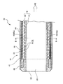
- FIG. 13 is a longitudinal sectional view showing an example of the catheter 10, and shows only the distal end portion of the catheter 10.
- 14 is a cross-sectional view taken along the line II-II in FIG. Fig.15 (a) and (b) are figures which show the catheter 10 which concerns on embodiment.
- FIG. 16 is a cross-sectional view showing the vicinity of the branch portion of the hollow tube 32 from the sheath 16.
- a medical device for example, the catheter 10) according to the present embodiment includes a long and flexible main body (sheath 16), and an operation line 40 embedded in the main body and having a distal end fixed to the distal end of the main body. And a hand operating section 70 provided at the base end of the main body and connected to the base end of the operation line 40.
- the medical device further includes a bending operation unit 730 provided in the hand operation unit 70 and a sag amount adjusting operation unit 770 provided in the hand operation unit 70.
- the bending operation unit 730 is for performing an operation of bending the main body by pulling the operation line 40.
- the slack amount adjusting operation unit 770 is for performing an operation of adjusting the amount of operation line 40 fed from the hand operation unit 70 without changing the pulling amount of the operation line 40 by the bending operation unit 730. Details will be described below.
- the catheter 10 is a suitable example that is an intravascular catheter used by being inserted into a blood vessel. More specifically, it is a preferred example that the catheter 10 is of a size that allows entry into any of the eight sub-regions of the liver.
- the catheter 10 has a sheath 16 as a long main body.
- the predetermined length region including the distal end (tip) DE of the catheter 10 (and the sheath 16) is referred to as the distal end portion 15 of the catheter 10 (and the sheath 16).
- the predetermined length region including the proximal end (proximal end) PE of the catheter 10 (and the sheath 16) is referred to as the proximal end (proximal end) 17 of the catheter 10 (and the sheath 16) (see FIG. 15).
- a main lumen 20 and a sub-lumen 30 are formed inside the sheath 16.
- the main lumen 20 and the sub-lumen 30 extend along the longitudinal direction (the left-right direction in FIG. 13) of the sheath 16 (the catheter 10).
- the main lumen 20 is disposed at the center of the transverse cross section (cross section orthogonal to the longitudinal direction) of the sheath 16, and the sub-lumen 30 is disposed around the main lumen 20. More specifically, in the cross section, the sub-lumens 30 are arranged at rotationally symmetric positions with respect to the center of the main lumen 20.
- the catheter 10 has, for example, a plurality of sub-lumens 30.
- Each sub-lumen 30 has a smaller diameter than the main lumen 20.
- the sub-lumens 30 and the main lumen 20 and the sub-lumen 30 are arranged separately from each other.
- the plurality of sub-lumens 30 are distributed around the main lumen 20.
- the number of sub-lumens 30 is two, and the sub-lumens 30 are arranged around the main lumen 20 at intervals of 180 degrees.
- the operation lines 40 are respectively inserted into the sub-lumens 30. That is, the catheter 10 has two operation lines 40a and 40b.
- the operation line 40 is movable relative to the sub-lumen 30 in the longitudinal direction of the sub-lumen 30 by sliding with respect to the peripheral wall of the sub-lumen 30. That is, the operation line 40 is slidable in the longitudinal direction of the sub-lumen 30.
- the operation wire 40 may be formed of a single wire, but may be a stranded wire formed by twisting a plurality of thin wires.
- the number of fine wires constituting one stranded wire is not particularly limited, but is preferably 3 or more.
- a suitable example of the number of thin wires is three or seven.
- the number of fine lines is 3, the three fine lines are arranged point-symmetrically in the cross section.
- the number of fine lines is seven, the seven fine lines are arranged point-symmetrically in a honeycomb shape in the cross section.
- the material of the wire constituting the operation wire 40 (or the fine wire constituting the stranded wire)
- Poly paraphenylene benzobisoxazole
- PBO polyether ether ketone
- PES polyphenylene sulfide
- PBT polybutylene terephthalate
- PI polyimide
- PTFE polytetrafluoroethylene
- Polymer fibers can be used.
- examples of the structure of the sublumen 30 include the following two structures.
- a preformed hollow tube 32 is embedded in an outer layer 60 (described later) along the longitudinal direction of the sheath 16, and the hollow tube 32 is The lumen is sublumen 30. That is, in these examples, the sub-lumen 30 is constituted by the lumen of the hollow tube 32 embedded in the sheath 16.
- the hollow tube 32 can be made of, for example, a thermoplastic resin.
- thermoplastic resin include low friction resins such as polytetrafluoroethylene (PTFE) and polyetheretherketone (PEEK).
- the sub-lumen 30 is formed by forming a long hollow along the longitudinal direction of the sheath 16 in the outer layer 60 (described later).
- the sheath 16 includes, for example, an inner layer 21, an outer layer 60 formed around the inner layer 21, and a coat layer 64 formed around the outer layer 60.
- the inner layer 21 is made of a tubular resin material.
- a main lumen 20 is formed at the center of the inner layer 21.
- the outer layer 60 is made of the same or different resin material as the inner layer 21.
- the sub-lumen 30 is formed inside the outer layer 60.
- the coat layer 64 constitutes the outermost layer of the catheter 10 and is made of a hydrophilic material.
- the coat layer 64 may be formed only in a region extending over a part of the distal end portion 15 of the sheath 16, or may be formed over the entire length of the sheath 16.
- the catheter 10 further includes a coil 50 wound around the inner layer 21.
- the coil 50 is configured by, for example, bending one or more wire rods 52 formed of an elastic body such as metal or resin in a spiral shape.
- the coil 50 is included in the outer layer 60, for example.
- the sublumen 30 is formed outside the coil 50 inside the outer layer 60.
- the catheter 10 may have a blade layer (not shown) instead of the coil 50.
- the blade layer is formed by knitting a wire in a mesh shape, and is disposed at the same position as the coil 50.
- a ring-shaped marker 66 made of a material that does not transmit radiation such as X-rays is provided.
- the marker 66 is made of a metal material such as platinum.
- the marker 66 is provided around the main lumen 20 and inside the outer layer 60.
- the radius of the main lumen 20 is about 200 to 300 ⁇ m
- the thickness of the inner layer 21 is about 10 to 30 ⁇ m
- the thickness of the outer layer 60 is about 50 to 150 ⁇ m
- the outer diameter of the coil 50 is 500 to 860 ⁇ m
- the inner diameter of the coil 50 is the diameter. It can be 420 to 660 ⁇ m.
- the radius (distance) from the axial center of the catheter 10 to the center of the sublumen 30 is about 300 to 450 ⁇ m
- the inner diameter (diameter) of the sublumen 30 is 40 to 100 ⁇ m.
- the thickness of the operation line 40 is about 30 to 60 ⁇ m.
- the outermost diameter (radius) of the catheter 10 is about 350 to 490 ⁇ m, that is, the outer diameter is less than 1 mm in diameter.
- the tip 41 of the operation line 40 is fixed to the distal end 15 of the sheath 16.
- a mode in which the tip 41 of the operation line 40 is fixed to the distal end 15 is not particularly limited.
- the tip 41 of the operating line 40 may be welded or fastened to the marker 66, welded to the distal end 15 of the sheath 16, or the distal end of the marker 66 or the sheath 16 with an adhesive. 15 may be adhered and fixed.
- the sublumen 30 is open at least on the proximal end 17 side of the catheter 10.
- the base end portion of each operation line 40 protrudes from the opening of the sub-lumen 30 toward the proximal end PE.
- the base end portion of each operation line 40 is connected to the bending operation portion 730 (FIG. 15) of the hand operation portion 70 provided at the proximal end portion 17 of the sheath 16.
- the bending operation unit 730 is a mechanism that bends the distal end portion 15 of the catheter 10 by the operator pulling the two operation lines 40 individually.
- the hand operation unit 70 includes a main body case 700, a bending operation portion 730 provided in the main body case 700, and a hub 790 attached to the rear end portion of the main body case 700. ,have.
- the distal end side (FIGS. 1 (a) to (c) and leftward in FIG. 2) of the catheter 10 (FIG. 1) is front (front), and the proximal end side (FIG. 1 (a) to FIG. (C), (right side in FIG. 2) is referred to as rear (rear).
- the upper side of FIGS. 1B, 1D, and 1E and FIG. Further, the upper side of FIG. 1A is considered to be right (right), and the lower side is considered to be left (left).
- the definition of these directions is only a specification for convenience of explanation, and does not specify the direction in the usage state of the hand operation unit 70.
- a passage hole 707 through which the base end portion of the sheath 16 passes from the outside to the inside of the body case 700 is formed at the front end portion of the main body case 700, and a part of the base end portion of the sheath 16 is formed through the passage hole 707. It is introduced into the main body case 700.
- the proximal end of the sheath 16 is introduced into the front end portion of the hub 790 and fixed to the front end portion (FIG. 2).
- the hub 790 is a cylindrical body in which a hollow 791 that penetrates the hub 790 forward and backward is formed.
- the inner diameter of the rear part of the hub 790 is larger than the inner diameter of the front part.
- the hollow 791 of the hub 790 communicates with the main lumen 20 of the sheath 16.
- An injector (syringe) (not shown) can be inserted into the hub 790 from behind. By injecting a liquid such as a chemical solution into the hub 790 with this injector, the liquid is supplied to the distal end of the sheath 16 via the main lumen 20, and the liquid is supplied from the distal end of the sheath 16 into the body cavity of the patient. can do.
- the bending operation part 730 is formed in a disk shape, for example.
- the bending operation unit 730 is pivotally supported by the main body case 700 so as to be rotatable with respect to the main body case 700 about a rotation axis orthogonal to the plate surface.
- the bending operation unit 730 has a dial operation unit 760 operated by an operator.
- the dial operation unit 760 is formed in a disc shape.
- the cylindrical peripheral surface 762 of the dial operation unit 760 is provided with, for example, a gear-shaped unevenness so that the operator can easily operate the side peripheral surface 762 with a finger.
- a portion where the bending operation unit 730 is disposed is formed in a disk shape in accordance with the outer shape of the bending operation unit 730, for example.
- a central portion of the main body case 700 in the front-rear direction is referred to as a disk-shaped portion 701.
- the disk-shaped part 701 and the bending operation part 730 are disposed, for example, in the center part of the main body case 700 in the front-rear direction.
- the disc-shaped part 701 bulges in an arc shape in the left-right direction as compared with the front part 702 and the rear part 703 of the main body case 700.
- openings 708 that communicate the inside and outside of the main body case 700 are formed in an arc shape on both the left and right sides of the disc-shaped portion 701, and the side peripheral surface of the dial operation portion 760 is formed through the opening 708. 762 is partially exposed to the outside of the main body case 700 in the circumferential direction. Accordingly, the operator can perform an operation of rotating the dial operation unit 760 around the rotation axis by placing a finger on the side peripheral surface 762 from both the left and right sides of the hand operation unit 70. By this operation, the distal end portion of the catheter 10 can be bent (details will be described later).
- the bending operation part 730 is rotatable with respect to the main body case 700 by being pivotally supported by the shaft part 713 of the main body case 700.
- the main body case 700 includes, for example, a lower case 710 constituting the lower half of the main body case 700 and an upper case 720 constituting the upper half of the main body case 700.
- the lower case 710 is formed in a flat semi-housing shape that opens upward.
- the upper case 720 is formed in a flat semi-casing shape that opens downward.
- the lower case 710 and the upper case 720 are assembled to each other so that the opening at the upper end of the lower case 710 and the opening at the lower end of the upper case 720 are aligned, and these are fixed by a fastening member 705 (FIG. 1A) such as a screw.
- the main body case 700 is configured by being fixed to each other (FIG. 1).
- a sheath disposition groove 715 for positioning the sheath 16 is formed at the bottom of the inner surface of the lower case 710 so as to extend in the front-rear direction.
- the lower case 710 has a shaft portion 713 that pivotally supports the bending operation portion 730.
- the shaft portion 713 is composed of a pair of left and right divided shaft portions 713a that are arranged apart from each other. In a plan view, the sheath disposition groove 715 passes between the pair of split shaft portions 713a.
- Each divided shaft portion 713a is a semicircular columnar body in a plan view, and stands upward from the inner bottom surface of the lower case 710.
- the shaft portion 713 including the pair of divided shaft portions 713a has a cylindrical outer shape as a whole.
- the opposing surfaces of the pair of split shaft portions 713a are parallel to each other.
- an insertion pin 723 that hangs downward from the inner top surface of the upper case 720 is formed at a position facing the shaft portion 713 in the upper case 720.
- the insertion pin 723 is fitted between the upper portions of the pair of split shaft portions 713a (see FIG. 2). Thereby, the distance between the pair of split shaft portions 713a is kept constant, and the diameter of the shaft portion 713 is kept constant.
- a sheath presser 721 that protrudes toward the lower case 710 is formed at the front end of the upper case 720 (FIG. 4).
- a notch-shaped portion 711 facing the sheath pressing portion 721 is formed at the front end portion of the lower case 710 (FIG. 3).
- the sheath pressing portion 721 is inserted into the notch-shaped portion 711, and the sheath pressing portion 721 partially presses and fixes the sheath 16 against the bottom of the notch-shaped portion 711 (FIG. 2).
- the passage hole 707 is configured by combining a notch-shaped portion 711 and a sheath pressing portion 721.
- the bottom of the notch-shaped portion 711 is formed to the same depth as the sheath disposition groove 715 (FIG. 5C).
- a hub holding recess 712 is formed at the rear end of the lower case 710 (FIG. 3).
- the hub holding recess 712 is disposed adjacent to the rear of the sheath placement groove 715.
- a hub holding recess 722 is formed at the rear end of the upper case 720 (FIG. 4).
- the hub 790 is fixed to the main body case 700 by sandwiching and holding the front portion 792 of the hub 790 by the hub holding recess 712 and the hub holding recess 722 (FIG. 2).
- the lower case 710 has a circular central portion in the front-rear direction, and notch-shaped portions 718 are formed symmetrically on both left and right sides of the central portion.
- the upper case 720 has a circular central portion in the front-rear direction, and notched portions 728 are formed symmetrically on the left and right sides of the central portion.
- the opening 708 (FIG. 1) is configured by combining the notch shape portion 718 and the notch shape portion 728.
- the hand operation unit 70 further includes a guide unit 780 disposed in front of the bending operation unit 730 in the main body case 700.
- the guide portion 780 includes a pair of left and right legs 781 fixed to the lower case 710, a beam-like portion 782 laid between the upper portions of the pair of legs 781, and each leg portion. And a pair of left and right columnar portions 783 standing above each of 781.
- the region surrounded by the pair of leg portions 781 and the beam-like portion 782 constitutes a passage gate 784 that allows the sheath 16 to pass through (see FIG. 2).
- Each of the pair of leg portions 781 is formed with an insertion hole 788 opening downward.
- a pair of left and right fixing pins 714 for fixing the guide part 780 are formed on the bottom surface of the lower case 710 so as to stand upward (FIG. 3).
- the corresponding fixing pins 714 are inserted into the respective insertion holes 788, and the upper end surfaces of the respective columnar portions 783 are in contact with the top surface of the upper case 720 (FIG. 2).
- the guide part 780 is fixed in the main body case 700.
- the upper case 720 has a support portion 724 formed so as to hang downward from the inner top surface thereof, and the back surface of the guide portion 780 is supported by the support portion 724 (FIG. 2). .
- the pair of columnar portions 783 are each formed in a columnar shape.
- the beam-like portion 782 is formed in a shape in which at least its upper surface protrudes upward in an arc shape. Further, a boundary portion 785 between the side peripheral surface of the columnar portion 783 and the upper surface of the beam-shaped portion 782 is chamfered into an arcuate concave curved surface shape when viewed from the front.
- the hollow tube 32 is branched from the sheath 16 at the front end portion of the hand operating portion 70, and is routed from the front to the rear of the guide portion 780 through a pair of columnar portions 783 (FIG. 11 ( a)).
- the hollow tube 32 is engaged with the upper surface of the beam-shaped portion 782, the boundary portion 785, and the side peripheral surface of each columnar portion 783 facing the other columnar portion 783.
- the columnar portion 783 has a columnar shape
- the upper surface of the beam-shaped portion 782 has an arc shape
- the boundary portion 785 has a concave curved surface shape
- the hollow tube 32 is damaged by contact with the guide portion 780. Is suppressed.
- the bending operation unit 730 includes a take-up reel 740 that winds up the operation line 40, a dial operation unit 760 for the operator to rotate the take-up reel 740, a limiter member 750, have.
- the take-up reel 740 has a disc-shaped main body 741.
- a shaft support hole 743 that passes through the front and back of the main body 741 is formed at the center of the main body 741 in plan view.
- the shaft support hole 743 is circular in plan view.
- an accommodation recess 744 that accommodates a part of the limiter member 750 (a pair of spring-like bodies 752 (described later)) is formed on the peripheral edge of the shaft support hole 743.
- the shape of the outer peripheral wall surface of the housing recess 744 has a corrugated shape including a plurality of corrugated recesses 745 arranged repeatedly along the circumference.
- a slit-like groove 741a that circulates around the main body portion 741 is formed on the side surface of the main body portion 741, so that the intermediate portion in the vertical direction of the main body portion 741 is partially reduced in diameter.
- a winding body portion 742 that winds up the operation line 40 is formed in the main body portion 741.
- the winding body 742 has a cylindrical shape that is coaxial with the outer peripheral surface of the main body 741.
- a plurality of concave portions 741b having a circular arc shape in plan view are formed on the upper surface side of the main body portion 741. These concave portions 741b are arranged on the same diameter and coaxial circumference as the winding body portion 742.
- the weight of the main body 741 is reduced by the recesses 741b.
- openings arranged at the same position as the recess 741b in a plan view may be formed, and these openings may be communicated with at least the innermost part of the groove 741a in the main body 741. In this case, the winding state of the operation line 40 around the winding body 742 can be visually recognized from above the winding reel 740 through the opening.
- An annular locking recess 749 is formed on the peripheral edge of the shaft support hole 743 on the back surface of the main body 741 (FIG. 7B).
- a locking claw 756 (described later) of the limiter member 750 is locked to the locking recess 749.
- a pair of left and right accommodation recesses 746 for accommodating the sag amount adjusting operation portion 770 are formed on the upper surface side of the peripheral edge portion of the main body portion 741. These housing recesses 746 are arranged around the housing recess 744 at intervals of 180 degrees. The lowermost portion of the housing recess 746 communicates with the groove 741a except for a portion corresponding to a support base 747 described later.
- Each housing recess 746 has a rectangular shape in plan view (FIG. 7A) and a rectangular shape in side view (FIG. 7D).
- Each housing recess 746 is formed deeper than the groove 741a in the radial direction of the main body portion 741 (up to a position near the radial center of the main body portion 741).
- the bottom surface of the housing recess 746 in other words, the portion facing the housing recess 746 on the top surface of the winding body 742 is the same as the top surface of the groove 741a (upper surface in FIGS. 7C and 7D).
- a support base 747 located at a height is formed.
- the lower surface of the sagging amount adjusting operation unit 770 is the same height as the top surface of the groove 741a, that is, the same height as the upper end of the winding body 742. Retained.
- a pair of protrusions 748 extending in the vertical direction are formed on the inner surface of the housing recess 746 at the end portion of the main body 741 in the radial direction so as to face each other. These protrusions 748 suppress the dropout of the sag amount adjusting operation portion 770 from the housing recess 746 (see FIG. 5A).
- the dial operation unit 760 By operating the dial operation unit 760 and rotating the take-up reel 740 around the axis, the amount of winding of the operation line 40 by the take-up body 742 is increased, and the operation line 40 is pulled. be able to. In addition, the tension
- the dial operation unit 760 has a disc-shaped main body 761.
- the outer diameter of the main body 761 is larger than the outer diameter of the main body 741 of the take-up reel 740 (FIG. 2).
- the dial operation portion 760 and the take-up reel 740 are arranged coaxially with each other, but the side peripheral surface 762 of the main body portion 761 of the dial operation portion 760 is flatter than the main body portion 741 of the take-up reel 740. Located outward in view.
- An insertion hole 763 is formed in the center of the main body 761 so as to penetrate the main body 761 on the front and back sides.
- a plurality of locking recesses 764 for locking locking protrusions 755 (described later) of the limiter member 750 are formed on the inner peripheral surface of the insertion hole 763.
- Each locking recess 764 has a linear groove shape extending from the upper end to the lower end of the main body 761.
- a plurality of locking recesses 764 are formed intermittently in the circumferential direction of the insertion hole 763, and the shape of the fitting hole 763 and the plurality of locking recesses 764 combined is a gear shape.
- a donut-shaped accommodation recess 765 is formed on the back surface of the main body 761.
- the housing recess 765 houses the upper portion of the peripheral edge 741c (FIG. 7A) of the take-up reel 740 (see FIG. 2).
- the peripheral edge 741 c is a portion around the accommodation recess 744 in the take-up reel 740.
- the limiter member 750 rotates around the axis integrally with the dial operation unit 760, and transmits the rotational driving force from the dial operation unit 760 to the take-up reel 740. However, the limiter member 750 transmits the rotational driving force from the dial operation unit 760 to the take-up reel 740 only when the tension of the operation line 40 is within a predetermined range.
- the limiter member 750 has a cylindrical main body 751 and a spring-like body 752.
- a shaft support hole 754 that penetrates the front and back of the main body 751 is formed in the center of the main body 751.
- the shaft support hole 754 is circular in plan view.
- the limiter member 750 is pivotally supported with respect to the main body case 700 by inserting the shaft portion 713 of the main body case 700 into the shaft support hole 754 (FIG. 2).
- the spring-like body 752 is provided, for example, at the center of the main body 751 in the vertical direction, and projects outward from the main body 751 in the horizontal direction.
- the limiter member 750 has, for example, a pair of spring-like bodies 752.
- the spring-like body 752 is formed in a substantially C shape in plan view, and both ends thereof are connected to the outer peripheral surface of the main body 751. Between the spring-like body 752 and the main body 751, an opening 757 having a substantially C shape in plan view is formed.
- An engagement protrusion 753 is formed at the center of the arc-shaped (arch-shaped) portion of the spring-like body 752.
- the engaging protrusion 753 is a corrugated protrusion that protrudes outward in the horizontal direction.
- Each engagement protrusion 753 is engaged with any one of the plurality of corrugated recesses 745 of the take-up reel 740 (see FIG. 5A).
- the spring-like body 752 can be elastically deformed in the direction in which the engagement protrusion 753 approaches the main body 751 (the direction in which the opening 757 narrows).
- the main body 751 includes an upper protrusion 751 a that protrudes upward from the spring-like body 752 and a lower protrusion that protrudes downward from the spring-like body 752. 751b.
- the upper protrusion 751a is formed to have a smaller diameter than the lower protrusion 751b.
- a plurality of locking projections 755 extending in the vertical direction are intermittently formed on the side peripheral surface of the upper protrusion 751a in the circumferential direction of the side peripheral surface.
- the plurality of locking projections 755 and the locking recesses 764 of the dial operation unit 760 correspond one-to-one.
- the upper projecting portion 751a is fitted in the fitting hole 763 of the dial operation portion 760, and each of the locking projections 755 is locked with the corresponding locking recess 764.
- the limiter member 750 cannot rotate about the axis with respect to the dial operation unit 760, and the limiter member 750 rotates integrally with the dial operation unit 760. It can be said that the dial operation part 760 is pivotally supported by the shaft part 713 via the limiter member 750.
- the lower end surface of the lower projecting portion 751b is in contact with the bottom surface of the lower case 710, and the upper end surface of the upper projecting portion 751a is in contact with or close to the top surface of the upper case 720. Thereby, the drop-off of the limiter member 750 from the shaft portion 713 is suppressed. Further, the upper end surface of the upper protruding portion 751a is in contact with or close to the top surface of the upper case 720, so that the dial operation portion 760 is prevented from falling off from the upper protruding portion 751a.
- the downward projecting portion 751b is fitted in the shaft support hole 743 of the take-up reel 740.
- a locking claw 756 is formed at the lower end of the downward projecting portion 751b.
- the limiter member 750 has, for example, a pair of locking claws 756 disposed around the shaft support hole 754 at intervals of 180 degrees.
- Each locking claw 756 projects outward from the cylindrical outer peripheral surface of the downward projecting portion 751b. Each locking claw 756 is locked to the locking recess 749 of the take-up reel 740. Thereby, the limiter member 750 and the take-up reel 740 are integrated with each other.
- slits 751c extending in the vertical direction are formed in portions adjacent to both sides of the locking claw 756 in the circumferential direction.
- the latching claw 756 can be elastically deformed in the radial direction of the downward projecting portion 751b.
- the locking claw 756 is elastically deformed toward the center in the radial direction of the downward projecting portion 751b, thereby enabling smooth insertion. ing.
- the locking claw 756 When the downward projecting portion 751b is fitted into the shaft support hole 743, the locking claw 756 is elastically returned outward in the radial direction of the downward protruding portion 751b, and the locking claw 756 is in contact with the locking recess 749. And locked.
- the limiter member 750 and the take-up reel 740 are mutually rotatable around the axis in an integrated state.
- the locking recess 749 of the take-up reel 740 is formed in an annular shape as described above, when the limiter member 750 rotates relative to the take-up reel 740, the locking claw 756 It moves in an arc along 749.
- the spring-like body 752 is housed in the housing recess 744 of the take-up reel 740 (see FIGS. 5A and 5C).
- the limiter member 750 transmits the rotational driving force from the dial operation unit 760 to the take-up reel 740 only when the tension of the operation line 40 during the pulling operation is within a predetermined range. When the tension of the operation line 40 during the pulling operation exceeds a predetermined range, the limiter member 750 rotates idly with respect to the take-up reel 740.
- the engaging protrusion 753 of the spring-like body 752 is engaged with any one of the corrugated recesses 745 of the take-up reel 740.
- the spring-like body 752 performs an elastic return operation after the engaging protrusion 753 is elastically deformed in a direction approaching the main body 751.
- the engaging protrusion 753 newly engages with the corrugated recess 745 adjacent to the corrugated recess 745 that has been engaged so far.
- the spring-like body 752 is elastically deformed in this way, and the limiter member 750 is idled with respect to the take-up reel 740. Even if the 760 is rotated, the rotational driving force is not transmitted to the take-up reel 740 and the take-up reel 740 does not rotate. As a result, the tension of the operation line 40 is maintained within a predetermined range.
- the hand operation unit 70 has two sag amount adjusting operation units 770 (sag amount adjusting operation units 770a and 770b).
- the base end of the operation line 40 is fixed to each sag amount adjusting operation portion 770.
- Each slack amount adjusting operation portion 770 is accommodated in the corresponding accommodating recess 746 of the take-up reel 740 and is held by the take-up reel 740. That is, in the case of this embodiment, the sag amount adjusting operation unit 770 is provided in the bending operation unit 730.
- the sag amount adjusting operation unit 770 has a rounded polygonal columnar main body 771. That is, each of the ridge lines 775 (FIG. 10C) of the main body 771 is chamfered. For this reason, as shown in FIG.10 (c), the external shape (cross-sectional shape orthogonal to an axial center) of the side surface and side cross section of the main-body part 771 is a rounded polygonal shape, It has two opposing surfaces that are opposed to each other (except for a location where a winding groove 772 and an operation portion 774 described later are formed).
- the main body 771 has, for example, a rounded octagonal prism shape. That is, the side surface shape and the side cross-sectional shape of the main body 771 are rounded octagonal shapes.
- the main body portion 771 is formed with a winding groove (groove) 772 that circulates around the main body portion 771 around its body.
- the operation wire 40 is wound around the winding groove 772.
- the winding path of the winding groove 772 passes on the circumference centering on the central axis of the main body 771.
- the central axis (axial center) of the main body 771 is a straight line passing through the center of one end surface 776 of the main body 771 and the center of the other end surface 777.
- the cross-sectional shape of the winding groove 772 is formed in an arc shape.
- the operation line 40 is prevented from being damaged due to the contact between the winding groove 772 and the operation line 40.
- a fixing hole 773 for fixing the base end of the operation line 40 to the main body 771 is formed in the main body 771.
- the fixing hole 773 extends, for example, in the diameter direction of a circle corresponding to the winding path of the winding groove 772.
- the fixing hole 773 passes through the main body 771, and both ends of the fixing hole 773 communicate with the winding groove 772.
- an operation portion 774 for performing an operation of rotating the main body portion 771 around its central axis is formed.
- the operation part 774 is a linear groove
- the main body 771 can be rotated by inserting the tip of a tool such as a flat-blade screwdriver into the operation unit 774 and rotating the tool.
- the operation portion 774 may be a cross-shaped groove for enabling the main body portion 771 to be rotated using a Phillips screwdriver or the like.
- the operation portion 774 may be a linear or other shape protrusion.
- the other end surface 777 of the main body 771 is formed flat, for example.
- the sag amount adjusting operation portion 770 configured as described above is housed in the housing recess 746 of the take-up reel 740 in a state where the end portion on the end surface 777 side is supported on the support base 747.
- the inner wall surface 746a (FIGS. 7A and 7D) on the center side in the radial direction of the take-up reel 740 is formed flat.
- the end surface 777 of the main body 771 is in contact with or close to the inner wall surface 746a (see FIG. 5A).
- the end surface 777 slides relative to the inner wall surface 746a or the inner wall surface with a slight clearance. Guided by 746a.
- the distance between the pair of inner side surfaces 746 b (FIGS. 7A and 7D) facing each other in the circumferential direction of the take-up reel 740 is the same as the distance between the pair of facing surfaces of the main body 771.
- the distance E is set substantially equal to the distance E (FIG. 10C).
- any one set of opposing surfaces of the main body 771 is parallel to the inner side surface 746b, and the sag amount adjusting operation unit 770 is stabilized in posture. That is, except for a state in the middle of rotating the sag amount adjusting operation portion 770, any one set of opposing surfaces of the main body portion 771 is always parallel to the inner side surface 746b (FIGS. 5B and 12A). )reference). That is, at least a part of the main body 771 in the axial direction has a rounded polygonal cross-sectional shape orthogonal to the axial center.
- the take-up reel 740 of the bending operation unit 730 sandwiches two opposing surfaces in the part (a part of the main body 771 whose cross-sectional shape orthogonal to the axial direction is a rounded polygon).
- the main body 771 is held rotatably about the axis. For this reason, the rotation operation of the sag amount adjusting operation unit 770 is an operation accompanied by a click feeling.
- the magnitude of the force required to rotate the sag amount adjusting operation portion 770 is larger than the force required to idle the limiter member 750 with respect to the take-up reel 740. Therefore, the sag amount adjusting operation unit 770 does not rotate with the tension of the operation line 40.
- the hollow tube 32 branches off from the sheath 16 (a portion of the sheath 16 excluding the hollow tube 32) at the front end portion of the hand operation unit 70 (FIG. 11A). As shown in FIG. 16, the hollow tube 32 is branched from the portion excluding the hollow tube 32 in the sheath 16 so as to tear the outer peripheral portion of the sheath 16 from the hollow tube 32.
- the sheath pressing portion 721 of the upper case 720 holds and fixes the sheath 16 against the lower case 710 at the front end portion of the main body case 700, and the hollow tube 32 branched from the sheath 16 also has a lower case. It is pressed against 710 and fixed.
- the corner 725 of the rear end portion of the sheath pressing portion 721 is chamfered.
- the hollow tube 32 branched from the sheath 16 can be prevented from being damaged, and the sheath 16 can be prevented from being damaged.
- the hollow tube 32 engages with the guide portion 780 behind the sheath pressing portion 721, and further extends to the rear of the guide portion 780 (to the right in FIG. 11A).
- the operation line 40 does not directly contact the guide part 780 but the hollow tube 32 surrounding the operation line 40 contacts the guide part 780, stress applied to the operation line 40 is reduced. be able to.
- the operation line 40 is exposed from the hollow tube 32 between the guide portion 780 and the take-up reel 740. That is, the base end 32 a of the hollow tube 32 is located between the guide portion 780 and the take-up reel 740.
- the operation line 40 exposed from the hollow tube 32 is wound (engaged) on the winding body portion 742 of the winding reel 740 and wound on the winding groove 772 of the sag amount adjusting operation portion 770. Yes.
- the operation line 40 is wound around the take-up reel 740 by a route that circulates around 270 degrees around the take-up reel 740. That is, one operation line 40a is engaged with the upper left portion in FIG. 11A with respect to the take-up reel 740, and passes through the upper end portion and the right end portion in FIG. It is wound around a sag amount adjusting operation unit 770 (sag amount adjusting operation unit 770a) arranged at the lower end in (a). Further, the other operation line 40b engages with the lower left portion in FIG. 11A with respect to the take-up reel 740, and passes through the lower end portion and the right end portion in FIG. It is wound around a sag amount adjusting operation unit 770 (sag amount adjusting operation unit 770b) arranged at the upper end in (a).
- the base ends of the operation lines 40a and 40b are inserted into the fixing holes 773 of the sag amount adjusting operation portions 770a and 770b, and the sag is formed in the fixing holes 773 by, for example, an adhesive 779 (FIG. 11B). It is fixed to the amount adjustment operation unit 770. That is, in the case of this embodiment, the sag amount adjusting operation unit 770 is provided in the bending operation unit 730, and the base end of the operation line 40 is connected to the sag amount adjusting operation unit 770.
- the sag amount adjusting operation unit 770 includes the winding unit that winds the operation line 40, and the winding unit rotates the winding unit around its axis to operate the operation line for the winding unit.
- a winding operation unit for performing an operation of adjusting the winding amount of 40 is provided.
- the winding unit is a main body unit 771, and the winding operation unit is an operation unit 774.
- a winding groove (groove) 772 that circulates around the main body 771 is formed on the peripheral surface of the main body 771, and the operation wire 40 is wound around the winding groove 772.
- a fixing hole 773 intersecting with the winding groove 772 is formed in the main body 771, and one end of the operation line 40 is fixed to the main body 771 in the fixing hole 773.
- the bending operation unit 730 rotates the winding reel 740 as a winding winding unit for winding the operation line 40 and the operation line 40 with respect to the winding reel 740 by rotating the winding reel 740.
- a dial operation unit 760 as a bending winding operation unit for performing an operation of adjusting the winding amount.
- the winding axis of the operation line 40 wound around the take-up reel 740 and the winding axis of the operation line 40 wound around the main body 771 are orthogonal to each other.
- the winding surface of the operation wire 40 wound around the take-up reel 740 and the winding surface of the operation wire 40 wound around the main body 771 are orthogonal to each other.
- the direction in which the operation line 40 is pulled out from the main body 771 substantially coincides with the tangential direction of the take-up reel 740 at the location where the main body 771 is disposed. For this reason, the operation line 40 wound around the take-up reel 740 is smoothly wound around the main body 771. Therefore, in the operation line 40, it is possible to reduce the stress applied to the boundary portion 45 between the portion wound around the take-up reel 740 and the portion wound around the main body portion 771.
- the operation amount from the hand operating portion 70 is increased.
- the amount by which the operation line 40 can be extended can be reduced, and the amount of sag of the operation line 40 can be reduced. With this operation, the tension of the operation line 40 increases.
- the operation line 40a will be described in detail with reference to FIGS.
- the main body portion 771 of the sag adjusting operation portion 770 is rotated in the direction of arrow A, the amount of operation wire 40 wound around the winding groove 772 increases, so that the operation wire 40a is located around the take-up reel 740.
- the operable amount of the operation line 40a from the hand operation unit 70 decreases, the amount of sag of the operation line 40 decreases, and the tension of the operation line 40 increases.
- the operation line 40 can be drawn out from the hand operation unit 70.
- the amount can be adjusted. That is, the sag amount adjusting operation unit 770 is for performing an operation for adjusting the amount by which the operation line 40 can be drawn from the hand operation unit 70 without changing the pulling amount of the operation line 40 by the bending operation unit 730. is there.
- the sag amount adjusting operation part 770 is not operated in the state where the main body case 700 is assembled.
- the dial operation unit 760 is covered with the peripheral edge.
- the sag amount adjusting operation unit 770 is operated from the side with the upper case 720 removed from the lower case 710 and the dial operation unit 760 removed from the limiter member 750.
- each notch shape portion 718 of the lower case 710 includes an operation notch shape for avoiding interference between a tool such as a flat-blade screwdriver and the lower case 710 when the slack amount adjusting operation portion 770 is rotated.
- a portion 717 is formed (FIG. 5A).
- the distal end portion 15 of the catheter 10 is moved to the distal end portion 15 of the catheter 10. Is given a tensile force via the one operation line 40. If the tensile force is greater than or equal to a predetermined value, the distal end portion 15 of the sheath 16 bends toward the sub-lumen 30 through which the operation line 40 is inserted, with the axis of the sheath 16 as a reference.
- the bending of the sheath 16 includes a mode in which the sheath 16 is bent in a “shape” and a mode in which the sheath 16 is bent like a bow.
- the distal end portion of the catheter 10 is drawn. 15 is given a tensile force via the other operation line 40. If the tensile force is greater than or equal to a predetermined value, the distal end portion 15 of the sheath 16 bends toward the sub-lumen 30 through which the operation line 40 is inserted, with the axis of the sheath 16 as a reference. That is, the distal end portion of the sheath 16 bends in the opposite direction to when the one operation line 40 is pulled.
- the distal end portion 15 of the catheter 10 is moved in the first direction and the second direction which is the opposite direction. Can be bent.
- the first direction and the second direction are included in the same plane.
- the direction of the distal end DE of the catheter 10 can be freely controlled by combining the torque operation for axially rotating the entire catheter 10 inserted into the endoscope and the pulling operation. Furthermore, the amount of bending of the distal end DE of the catheter 10 can be adjusted by adjusting the pulling amount of the operation line 40. For this reason, the catheter 10 of this embodiment can be made to approach in a desired direction, for example with respect to body cavities, such as a branching blood vessel.
- the limiter member 750 rotates idly with respect to the take-up reel 740, so that the tension of the operation line 40 is maintained within a predetermined range.
- each sag amount adjusting operation unit 770 is individually operated to individually adjust the sag amount and tension of the operation lines 40a and 40b.
- the operation lines 40a and 40b are wound around the take-up reel 740 by an equal amount, that is, the sag adjusting operation portion 770a is taken up by the take-up reel.
- the sag amount adjusting operation portion 770b located at the left end of the take-up reel 740, the sag amount and tension of the operation lines 40a and 40b are individually adjusted.
- the operation lines 40a and 40b may be adjusted so that there is no slack in the operation lines 40a and 40b in the sheath 16 on the distal end side of the hand operation unit 70, and the tensions of the operation lines 40a and 40b are substantially zero. Is possible.
- the hand operation unit 70 is provided with an amount by which the operation line 40 can be fed out from the hand operation unit 70 without changing the pulling amount of the operation line 40 by the bending operation unit 730.
- a sagging amount adjusting operation unit 770 is provided for performing an operation of adjusting the sag. Therefore, the tension of the operation line 40 can be adjusted by adjusting the amount of operation line 40 that can be drawn out from the hand operation unit 70 by operating the sag amount adjustment operation unit 770.
- a tensile force such as a constant force spring in Patent Document 1 does not act on the operation line 40.
- FIGS. 17A and 17B are schematic diagrams for explaining a sag adjustment operation unit 870 in the hand operation unit of the catheter according to the second embodiment, in which (a) is a plan view and (b) is a sag adjustment operation unit. 870 is a cross-sectional side view of 870.
- FIG. 17A is a schematic diagram for explaining a sag adjustment operation unit 870 in the hand operation unit of the catheter according to the second embodiment, in which (a) is a plan view and (b) is a sag adjustment operation unit. 870 is a cross-sectional side view of 870.
- the catheter according to the second embodiment is different from the catheter 10 according to the first embodiment only in the points described below, and is configured similarly to the catheter 10 in other points.
- the hand operation unit 70 has a sag amount adjusting operation unit 870 instead of the sag amount adjusting operation unit 770.
- the take-up reel 740 is not formed with an accommodation recess 746.
- the sag amount adjusting operation portion 870 includes an engaging portion 871 that engages with the operation line 40, and the engaging portion 871 intersects the extending direction of the operation line 40.
- a moving mechanism that moves in the direction (arrow E, F direction in FIG. 17) and a fixing mechanism that fixes the engaging portion 871 to the hand operating portion 70 at an arbitrary position.
- the engaging portion 871 is, for example, a pin-shaped member that stands above the bottom plate of the lower case 710.
- the operation line 40 is engaged with the engaging portion 871 via the hollow tube 32 between the columnar portion 783 of the guide portion 780 and the take-up reel 740.
- the hand operation unit 70 has a slack amount adjustment operation unit 870 (870a, 870b) individually corresponding to each of the operation lines 40a, 40b.
- the hollow tube 32 that encloses one operation line 40a is engaged with the engaging portion 871 of one sag amount adjusting operation portion 870a.
- the hollow tube 32 containing the other operation line 40b is engaged with the engaging portion 871 of the other sag adjusting operation portion 870a.
- Each operation line 40 is exposed from the hollow tube 32 between the engaging portion 871 and the take-up reel 740. That is, the proximal end 32 a of the hollow tube 32 is located between the engaging portion 871 and the take-up reel 740.
- Each operation line 40 turns around 270 degrees around the take-up reel 740 as in the first embodiment, and its base end is fixed to the fixing portion 875 of the take-up reel 740. That is, the base end of the operation line 40a is fixed to the fixing portion 875a, and the base end of the operation line 40b is fixed to the fixing portion 875b.
- the moving mechanism is constituted by a long hole 872 formed in the bottom plate of the lower case 710.
- the longitudinal direction of the long hole 872 is a direction intersecting (specifically, generally orthogonal) with respect to the extending direction of the hollow tube 32 between the columnar portion 783 of the guide portion 780 and the take-up reel 740. .
- the fixing mechanism includes, for example, a fixing screw 873 screwed into the engaging portion 871 from the back surface side of the lower case 710 through the long hole 872.
- the engaging portion 871 can be moved along the long hole 872 in the longitudinal direction of the long hole 872 to adjust the position of the engaging portion 871 to a desired position. ing. Further, the engaging portion 871 and the fixing screw 873 can be fixed to the lower case 710 by screwing the fixing screw 873 into the engaging portion 871.
- the lower end portion 874 of the engaging portion 871 is formed with an outer diameter that is the same as or slightly smaller than the lateral width of the long hole 872, and is inserted into the long hole 872. Therefore, when the engaging portion 871 is moved along the long hole 872 in the longitudinal direction of the long hole 872, the lower end portion 874 of the engaging portion 871 is guided by the long hole 872.
- the operation of the sag adjusting operation portion 870 is performed by adjusting the position of the engaging portion 871 in the longitudinal direction of the long hole 872 and fixing the engaging portion 871 to the lower case 710. To do. By performing such an operation, it is possible to adjust the amount of sag and tension of the operation line 40 by adjusting the amount by which the operation line 40 can be drawn from the hand operation unit 70.
- the number of catheter operation lines 40 is two has been described.
- the number of catheter operation lines 40 may be one, or may be three or more.
- the sag amount adjusting operation unit may be a modified example described below.
- the sag amount adjusting operation part of the modification has an operation line fixing part (not shown) to which the base end of the operation line 40 is fixed, and a fixing mechanism (not shown).
- the operation line fixing unit is provided in the bending operation unit 730 (for example, on the take-up reel 740) so as to be movable with respect to the bending operation unit 730 (for example, with respect to the take-up reel 740).
- the fixing mechanism can fix the operation line fixing portion to the bending operation portion 730 at an arbitrary position.
- the operation line fixing portion With the position of the operation line fixing portion relative to the bending operation portion 730 adjusted, the operation line fixing portion is fixed to the bending operation portion 730 by a fixing mechanism, whereby the operation line 40 can be fed out from the hand operation portion 70. And the amount of sag and tension of the operation line 40 can be adjusted.
- the bending operation unit 730 includes a bending winding unit (winding reel 740) that winds the operation line 40 and an operation line for the bending winding unit by rotating the bending winding unit.
- a winding operation unit for bending dial operation unit 760 for performing an operation of adjusting the winding amount of 40.
- fixed part is provided in the winding part for bending so that it can move along the circumferential direction of the winding part for winding (winding reel 740).
- the fixing mechanism can fix the operation line fixing portion to the bending operation portion 730 at an arbitrary position along the circumferential direction of the bending winding portion (winding reel 740).
- the limiter member 750 may not include the limiter member 750.
- the dial operation unit 760 and the take-up reel 740 can be integrally formed.
- the operation line 40 is bent so that the operation line 40 is pulled by an operation on the bending operation unit 730.
- the proximal end portion of the operation line 40 may be connected to a portion other than the bending operation portion 730 in the hand operation portion 70 that is engaged with the operation portion 730.
- a catheter is exemplified as a medical device, but the present invention is not limited to this example. That is, the present invention can also be applied to other medical devices (for example, endoscopes) that bend the main body using an operation line.
- medical devices for example, endoscopes
Landscapes
- Health & Medical Sciences (AREA)
- Life Sciences & Earth Sciences (AREA)
- Biophysics (AREA)
- Pulmonology (AREA)
- Engineering & Computer Science (AREA)
- Anesthesiology (AREA)
- Biomedical Technology (AREA)
- Heart & Thoracic Surgery (AREA)
- Hematology (AREA)
- Animal Behavior & Ethology (AREA)
- General Health & Medical Sciences (AREA)
- Public Health (AREA)
- Veterinary Medicine (AREA)
- Media Introduction/Drainage Providing Device (AREA)
Abstract
本発明は、操作線に極力ストレスが作用していない状態で、操作線のたるみ量を調節することができる医療機器に関する。本発明の医療機器(カテーテル(10))は、長尺で可撓性の本体部(シース(16))と、本体部に埋設され且つ先端が本体部の先端部に固定された操作線(40)と、本体部の基端部に設けられた手元操作部(70)と、を有する。操作線(40)の基端部は手元操作部(70)に連結されている。医療機器は、更に、手元操作部(70)に設けられた屈曲操作部(730)と、手元操作部(70)に設けられたたるみ量調節操作部(770)を有している。屈曲操作部(730)は、操作線(40)を牽引することにより本体部を屈曲させる操作を行うためのものである。たるみ量調節操作部(770)は、屈曲操作部(730)による操作線(40)の牽引量を変化させずに、手元操作部(70)からの操作線(40)の繰り出し可能量を調節する操作を行うためのものである。
Description
本発明は、医療機器に関する。
近年、先端部(以下「遠位端部」という)を屈曲させる操作を行うことにより、体腔への進入方向を変更可能に構成された、各種の医療機器が開発されている。その代表例として、たとえば、カテーテルが知られている。
特許文献1には、カテーテルの遠位端部に操作線を固定し、カテーテルの基端部(以下「近位端部」という)には操作線の牽引操作を行うための制御ハンドルを設け、制御ハンドルに対する牽引操作により操作線を牽引して、遠位端部を屈曲させる技術が記載されている。
制御ハンドルは、回転可能に軸支されたレバー構造を有し、このレバー構造には、プーリが設けられている。操作線の基端部は、プーリに掛けられて、カテーテルの先端側へ折り返されている。操作線の基端は、制御ハンドル内に設けられた定力バネに連結され、該定力バネにより、カテーテルの先端側へ引っ張られている。牽引操作は、レバー構造を軸周りに回転させることにより行うことができる。
このカテーテルにおいては、操作線の基端は定力バネにより引っ張られているため、操作線がたるみのない状態に維持されると考えられる。
このカテーテルは、更に、操作線の基端が所定の位置を越えてプーリ側へ移動することを阻止する停止部材を有している。停止部材は、牽引操作の際に定力バネの伸長を規制して確実に遠位端部を屈曲させるためのものと考えられる。
制御ハンドルは、回転可能に軸支されたレバー構造を有し、このレバー構造には、プーリが設けられている。操作線の基端部は、プーリに掛けられて、カテーテルの先端側へ折り返されている。操作線の基端は、制御ハンドル内に設けられた定力バネに連結され、該定力バネにより、カテーテルの先端側へ引っ張られている。牽引操作は、レバー構造を軸周りに回転させることにより行うことができる。
このカテーテルにおいては、操作線の基端は定力バネにより引っ張られているため、操作線がたるみのない状態に維持されると考えられる。
このカテーテルは、更に、操作線の基端が所定の位置を越えてプーリ側へ移動することを阻止する停止部材を有している。停止部材は、牽引操作の際に定力バネの伸長を規制して確実に遠位端部を屈曲させるためのものと考えられる。
特許文献1のカテーテルでは、操作線に対し、常に、定力バネによる引っ張り力以上の張力が作用する。しかし、操作線は極めて細い(例えば径が数十μm程度)ものであるため、操作線には、なるべくストレスが加わらないことが好ましい。
本発明は、上記の課題に鑑みなされたものであり、操作線に極力ストレスが作用していない状態で、操作線のたるみ量を調節することが可能なカテーテル等の医療機器を提供する。
本発明は、長尺で可撓性の本体部と、
前記本体部に埋設され、且つ、先端が前記本体部の先端部に固定された操作線と、
前記本体部の基端部に設けられ、且つ、前記操作線の基端部が連結された手元操作部と、
前記手元操作部に設けられ、前記操作線を牽引することにより前記本体部を屈曲させる操作を行うための屈曲操作部と、
前記手元操作部に設けられ、且つ、前記屈曲操作部による前記操作線の牽引量を変化させずに、前記手元操作部からの前記操作線の繰り出し可能量を調節する操作を行うためのたるみ量調節操作部と、
を有することを特徴とする医療機器を提供する。
前記本体部に埋設され、且つ、先端が前記本体部の先端部に固定された操作線と、
前記本体部の基端部に設けられ、且つ、前記操作線の基端部が連結された手元操作部と、
前記手元操作部に設けられ、前記操作線を牽引することにより前記本体部を屈曲させる操作を行うための屈曲操作部と、
前記手元操作部に設けられ、且つ、前記屈曲操作部による前記操作線の牽引量を変化させずに、前記手元操作部からの前記操作線の繰り出し可能量を調節する操作を行うためのたるみ量調節操作部と、
を有することを特徴とする医療機器を提供する。
この医療機器によれば、手元操作部には、屈曲操作部による操作線の牽引量を変化させずに、手元操作部からの操作線の繰り出し可能量を調節する操作を行うためのたるみ量調節操作部が設けられている。このため、牽引操作の非実行時に、たるみ量調節操作部を操作することで手元操作部からの操作線の繰り出し可能量を調節することにより、操作線のたるみ量を調節することができる。ここで、操作線には、特許文献1における定力バネなどの引っ張り力が作用しない。このため、操作線に極力ストレスが作用していない状態で、操作線のたるみ量を調節することが可能である。
本発明によれば、操作線に極力ストレスが作用していない状態で、操作線のたるみ量を調節することが可能である。
以下、本発明の実施形態について、図面を用いて説明する。なお、すべての図面において、同様の構成要素には同一の符号を付し、適宜に説明を省略する。
〔第1の実施形態〕
図1及び図2は第1の実施形態に係るカテーテル10(図15)の手元操作部70を示す図であり、このうち図1(a)は平面図、図1(b)は側面図、図1(c)は底面図、図1(d)は正面図、図1(e)は背面図、図2は側断面図である。
図3は手元操作部70の下部ケース710を示す図であり、このうち(a)は平面図、(b)は側断面図、(c)は底面図、(d)は正面図、(e)は背面図である。
図4は手元操作部70の上部ケース720を示す図であり、このうち(a)は平面図、(b)は側断面図、(c)は底面図、(d)は正面図、(e)は背面図である。
図5は手元操作部70から上部ケース720及びダイヤル操作部(屈曲操作部730を構成する)760を取り外した状態を示す図であり、このうち(a)は平面図、(b)は側面図、(c)は側断面図である。
図6は手元操作部70のガイド部780を示す図であり、このうち(a)は平面図、(b)は正面図、(c)は底面図、(d)は側断面図である。
図7は手元操作部70の巻取リール(屈曲操作部730を構成する)740を示す図であり、このうち(a)は平面図、(b)は底面図、(c)は正面図、(d)は側面図である。
図8は手元操作部70のダイヤル操作部760を示す図であり、このうち(a)は平面図、(b)は底面図、(c)は側面図である。なお、ダイヤル操作部760の正面図も、図8(c)と同様である。
図9は手元操作部70のリミッター部材750を示す図であり、このうち(a)は平面図、(b)は底面図、(c)は正面図、(d)は側面図である。
図10は手元操作部70のたるみ量調節操作部770を示す図であり、このうち(a)は平面図、(b)は正面図、(c)は側面図である。
図11は手元操作部70内における操作線40の経路を示す模式図であり、このうち(a)は平面図、(b)は側面図である。なお、図11(b)においては、操作線40の経路を分かりやすくするため、1本の操作線40のみを示している。
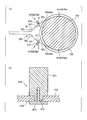
図12はたるみ量調節操作部770を用いた操作線40のたるみ量の調節操作を説明するための模式図であり、このうち(a)は側面図、(b)は平面図である。なお、図12(a)及び(b)においては、説明を分かりやすくするため、1本の操作線40のみを示している。
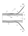
図13はカテーテル10の一例を示す縦断面図であり、カテーテル10の先端部のみを示している。
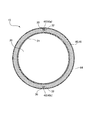
図14は図13のII-II断面図である。
図15(a)及び(b)は実施形態に係るカテーテル10を示す図である。このうち(a)は先端部を一方に屈曲させた状態を、(b)は先端部を他方に屈曲させた状態を、それぞれ示す。
図16はシース16からの中空管32の分岐部近傍を示す断面図である。
図1及び図2は第1の実施形態に係るカテーテル10(図15)の手元操作部70を示す図であり、このうち図1(a)は平面図、図1(b)は側面図、図1(c)は底面図、図1(d)は正面図、図1(e)は背面図、図2は側断面図である。
図3は手元操作部70の下部ケース710を示す図であり、このうち(a)は平面図、(b)は側断面図、(c)は底面図、(d)は正面図、(e)は背面図である。
図4は手元操作部70の上部ケース720を示す図であり、このうち(a)は平面図、(b)は側断面図、(c)は底面図、(d)は正面図、(e)は背面図である。
図5は手元操作部70から上部ケース720及びダイヤル操作部(屈曲操作部730を構成する)760を取り外した状態を示す図であり、このうち(a)は平面図、(b)は側面図、(c)は側断面図である。
図6は手元操作部70のガイド部780を示す図であり、このうち(a)は平面図、(b)は正面図、(c)は底面図、(d)は側断面図である。
図7は手元操作部70の巻取リール(屈曲操作部730を構成する)740を示す図であり、このうち(a)は平面図、(b)は底面図、(c)は正面図、(d)は側面図である。
図8は手元操作部70のダイヤル操作部760を示す図であり、このうち(a)は平面図、(b)は底面図、(c)は側面図である。なお、ダイヤル操作部760の正面図も、図8(c)と同様である。
図9は手元操作部70のリミッター部材750を示す図であり、このうち(a)は平面図、(b)は底面図、(c)は正面図、(d)は側面図である。
図10は手元操作部70のたるみ量調節操作部770を示す図であり、このうち(a)は平面図、(b)は正面図、(c)は側面図である。
図11は手元操作部70内における操作線40の経路を示す模式図であり、このうち(a)は平面図、(b)は側面図である。なお、図11(b)においては、操作線40の経路を分かりやすくするため、1本の操作線40のみを示している。
図12はたるみ量調節操作部770を用いた操作線40のたるみ量の調節操作を説明するための模式図であり、このうち(a)は側面図、(b)は平面図である。なお、図12(a)及び(b)においては、説明を分かりやすくするため、1本の操作線40のみを示している。
図13はカテーテル10の一例を示す縦断面図であり、カテーテル10の先端部のみを示している。
図14は図13のII-II断面図である。
図15(a)及び(b)は実施形態に係るカテーテル10を示す図である。このうち(a)は先端部を一方に屈曲させた状態を、(b)は先端部を他方に屈曲させた状態を、それぞれ示す。
図16はシース16からの中空管32の分岐部近傍を示す断面図である。
本実施形態に係る医療機器(例えば、カテーテル10)は、長尺で可撓性の本体部(シース16)と、本体部に埋設され且つ先端が本体部の先端部に固定された操作線40と、本体部の基端部に設けられ且つ操作線40の基端部が連結された手元操作部70と、を有する。
この医療機器は、更に、手元操作部70に設けられた屈曲操作部730と、手元操作部70に設けられたたるみ量調節操作部770と、を有している。
屈曲操作部730は、操作線40を牽引することにより本体部を屈曲させる操作を行うためのものである。
たるみ量調節操作部770は、屈曲操作部730による操作線40の牽引量を変化させずに、手元操作部70からの操作線40の繰り出し量を調節する操作を行うためのものである。
以下、詳細に説明する。
この医療機器は、更に、手元操作部70に設けられた屈曲操作部730と、手元操作部70に設けられたたるみ量調節操作部770と、を有している。
屈曲操作部730は、操作線40を牽引することにより本体部を屈曲させる操作を行うためのものである。
たるみ量調節操作部770は、屈曲操作部730による操作線40の牽引量を変化させずに、手元操作部70からの操作線40の繰り出し量を調節する操作を行うためのものである。
以下、詳細に説明する。
カテーテル10は、血管内に挿通させて用いられる血管内カテーテルであることが好適な一例である。より具体的には、カテーテル10は、肝臓の8つの亜区域の何れにも進入させることが可能な寸法のものであることが好適な一例である。
図13に示すように、カテーテル10は、長尺な本体部としてのシース16を有している。
なお、本明細書では、カテーテル10(並びにシース16)の遠位端(先端)DEを含む所定の長さ領域のことを、カテーテル10(並びにシース16)の遠位端部15という。同様に、カテーテル10(並びにシース16)の近位端(基端)PEを含む所定の長さ領域のことを、カテーテル10(並びにシース16)の近位端部(基端部)17(図15)という。
なお、本明細書では、カテーテル10(並びにシース16)の遠位端(先端)DEを含む所定の長さ領域のことを、カテーテル10(並びにシース16)の遠位端部15という。同様に、カテーテル10(並びにシース16)の近位端(基端)PEを含む所定の長さ領域のことを、カテーテル10(並びにシース16)の近位端部(基端部)17(図15)という。
シース16の内部には、メインルーメン20と、サブルーメン30とが形成されている。メインルーメン20及びサブルーメン30は、シース16の(カテーテル10の)長手方向(図13における左右方向)に沿って延在している。メインルーメン20は、例えば、シース16の横断面(長手方向に直交する断面)における中央に配置され、サブルーメン30は、メインルーメン20の周囲に配置されている。より具体的には、横断面において、サブルーメン30どうしは、メインルーメン20の中心を基準として、回転対称位置に配置されている。
図14に示すように、カテーテル10は、例えば、複数個のサブルーメン30を有している。各サブルーメン30は、メインルーメン20よりも小径である。
サブルーメン30どうし、並びに、メインルーメン20とサブルーメン30とは、互いに離間して個別に配置されている。複数のサブルーメン30は、例えば、メインルーメン20の周囲に分散して配置されている。図14の例では、サブルーメン30の数は2つであり、サブルーメン30は、メインルーメン20の周囲に180度間隔で配置されている。
これらサブルーメン30の内部には、それぞれ操作線40が挿通されている。すなわち、カテーテル10は、2本の操作線40a、40bを有する。
操作線40は、サブルーメン30の周壁に対して摺動することにより、サブルーメン30に対して相対的に、サブルーメン30の長手方向へ移動可能となっている。すなわち、操作線40は、サブルーメン30の長手方向に摺動可能となっている。
操作線40は、単一の線材により構成されていても良いが、複数本の細線を互いに撚りあわせることにより構成された撚り線であっても良い。
一本の撚り線を構成する細線の本数は特に限定されないが、3本以上であることが好ましい。細線の本数の好適な例は、3本又は7本である。細線の本数が3本の場合、横断面において3本の細線が点対称に配置される。細線の本数が7本の場合、横断面において7本の細線が点対称にハニカム状に配置される。
一本の撚り線を構成する細線の本数は特に限定されないが、3本以上であることが好ましい。細線の本数の好適な例は、3本又は7本である。細線の本数が3本の場合、横断面において3本の細線が点対称に配置される。細線の本数が7本の場合、横断面において7本の細線が点対称にハニカム状に配置される。
操作線40を構成する線材(或いは撚り線を構成する細線)の材料としては、低炭素鋼(ピアノ線)、ステンレス鋼(SUS)、チタンもしくはチタン合金などの可撓性の金属線のほか、ポリ(パラフェニレンベンゾビスオキサゾール)(PBO)、ポリエーテルエーテルケトン(PEEK)、ポリフェニレンスルフィド(PPS)、ポリブチレンテレフタレート(PBT)、ポリイミド(PI)もしくはポリテトラフルオロエチレン(PTFE)、ボロン繊維などの高分子ファイバーを用いることができる。
ここで、サブルーメン30の構造としては、例えば、以下の2通りの構造を例示できる。
1つ目の構造では、図13及び図14に示すように、予め形成された中空管32をシース16の長手方向に沿って外層60(後述)内に埋設し、その中空管32の内腔をサブルーメン30とする。すなわち、これらの例では、サブルーメン30は、シース16内に埋設された中空管32の内腔により構成されている。
中空管32は、例えば、熱可塑性樹脂により構成することができる。その熱可塑性樹脂としては、ポリテトラフルオロエチレン(PTFE)やポリエーテルエーテルケトン(PEEK)などの低摩擦樹脂が挙げられる。
2つ目の構造では、外層60(後述)内に、シース16の長手方向に沿う長尺な中空を形成することによって、サブルーメン30を形成する。
シース16は、より具体的には、例えば、内層21と、内層21の周囲に積層して形成された外層60と、外層60の周囲に形成されたコート層64と、を有する。
内層21は管状の樹脂材料からなる。内層21の中心には、メインルーメン20が形成されている。
外層60は、内層21と同種または異種の樹脂材料からなる。サブルーメン30は、外層60の内部に形成されている。
コート層64は、カテーテル10の最外層を構成するものであり、親水性の材料からなる。なお、コート層64は、シース16の遠位端部15の一部長さに亘る領域にのみ形成されていても良いし、シース16の全長に亘って形成されていても良い。
例えば、カテーテル10は、内層21の周囲に巻回されたコイル50を更に有している。コイル50は、例えば、金属或いは樹脂などの弾性体により構成された単数又は複数の線材52を螺旋状に屈曲させることにより構成されている。コイル50は、例えば、外層60に内包されている。
サブルーメン30は、外層60の内部において、コイル50の外側に形成されている。
サブルーメン30は、外層60の内部において、コイル50の外側に形成されている。
なお、カテーテル10は、コイル50に代えて、ブレード層(図示略)を有していても良い。ブレード層は、ワイヤをメッシュ状に編むことによって構成され、コイル50と同等の位置に配置される。
カテーテル10の遠位端部15には、X線等の放射線が不透過な材料からなるリング状のマーカー66が設けられている。具体的には、マーカー66は白金などの金属材料により構成されている。マーカー66は、例えば、メインルーメン20の周囲、且つ、外層60の内部に設けられている。
ここで、本実施形態のカテーテル10の各構成要素の代表的な寸法について説明する。
メインルーメン20の半径は200~300μm程度、内層21の厚さは10~30μm程度、外層60の厚さは50~150μm程度、コイル50の外径は直径500~860μm、コイル50の内径は直径420~660μmとすることができる。
カテーテル10の軸心からサブルーメン30の中心までの半径(距離)は300~450μm程度、サブルーメン30の内径(直径)は40~100μmとする。そして、操作線40の太さは30~60μm程度とする。
カテーテル10の最外径(半径)は350~490μm程度、すなわち外径が直径1mm未満である。これにより、本実施形態のカテーテル10は腹腔動脈などの血管に挿通可能である。
メインルーメン20の半径は200~300μm程度、内層21の厚さは10~30μm程度、外層60の厚さは50~150μm程度、コイル50の外径は直径500~860μm、コイル50の内径は直径420~660μmとすることができる。
カテーテル10の軸心からサブルーメン30の中心までの半径(距離)は300~450μm程度、サブルーメン30の内径(直径)は40~100μmとする。そして、操作線40の太さは30~60μm程度とする。
カテーテル10の最外径(半径)は350~490μm程度、すなわち外径が直径1mm未満である。これにより、本実施形態のカテーテル10は腹腔動脈などの血管に挿通可能である。
操作線40の先端部41は、シース16の遠位端部15に固定されている。操作線40の先端部41を遠位端部15に固定する態様は特に限定されない。たとえば、操作線40の先端部41をマーカー66に溶接或いは締結してもよく、シース16の遠位端部15に溶着してもよく、または接着剤によりマーカー66またはシース16の遠位端部15に接着固定してもよい。
サブルーメン30は、少なくともカテーテル10の近位端部17側において開口している。各操作線40の基端部は、サブルーメン30の開口から近位端PE側に突出している。例えば、各操作線40の基端部は、シース16の近位端部17に設けられた手元操作部70の屈曲操作部730(図15)に連結されている。
屈曲操作部730は、操作者が2本の操作線40を個別に牽引することにより、カテーテル10の遠位端部15を屈曲させる機構である。
次に、手元操作部70について詳細に説明する。
図1及び図2に示すように、手元操作部70は、本体ケース700と、本体ケース700に設けられている屈曲操作部730と、本体ケース700の後端部に取り付けられているハブ790と、を有している。
以下の説明では、カテーテル10(図15)の先端側(図1(a)~(c)、図2では左方)を前(前方)、カテーテル10の基端側(図1(a)~(c)、図2では右方)を後(後方)と称する。また、図1(b)、(d)、(e)及び図2の上側を上(上方)、下側を下(下方)と考える。また、図1(a)の上側を右(右方)、下側を左(左方)と考える。
ただし、これら方向の規定は、説明の便宜のために規定に過ぎず、手元操作部70の使用状態での方向を規定するものではない。
ただし、これら方向の規定は、説明の便宜のために規定に過ぎず、手元操作部70の使用状態での方向を規定するものではない。
本体ケース700の前端部には、シース16の基端部を本体ケース700の外部から内部へ通過させる通過孔707が形成され、この通過孔707を介して、シース16の基端部の一部分が本体ケース700内に導入されている。
シース16の基端は、ハブ790の前端部に導入され、該前端部に固定されている(図2)。ハブ790は、当該ハブ790を前後に貫通する中空791が内部に形成された筒状体である。ハブ790の後部の内径は、その前部の内径よりも拡径している。ハブ790の中空791は、シース16のメインルーメン20と連通している。
ハブ790には、その後方から、図示しない注入器(シリンジ)を挿入できるようになっている。この注入器よって、ハブ790内に薬液等の液体を注入することにより、メインルーメン20を介してその液体をシース16の先端へ供給し、該液体をシース16の先端から患者の体腔内へ供給することができる。
屈曲操作部730は、例えば、円板状に形成されている。屈曲操作部730は、その板面に直交する回転軸周りに、本体ケース700に対して回転可能となるように、本体ケース700に軸支されている。
屈曲操作部730は、操作者により操作されるダイヤル操作部760を有している。ダイヤル操作部760は、円板状に形成されている。ダイヤル操作部760の円筒状(環状とも言える)の側周面762には、該側周面762を操作者が指で操作しやすいように、例えば歯車状の凹凸加工が施されている。
本体ケース700において、屈曲操作部730が配置されている部位は、例えば、屈曲操作部730の外形形状に合わせて、円板状に形成されている。本体ケース700の前後方向における中央部のことを、円板状部701と称する。
円板状部701及び屈曲操作部730は、例えば、本体ケース700の前後方向における中央部に配置されている。円板状部701は、本体ケース700の前部702及び後部703と比べて、左右方向にそれぞれ円弧状に膨出している。
屈曲操作部730は、例えば、その大部分が円板状部701内に収容されている。ただし、例えば、円板状部701の左右両側部には、それぞれ本体ケース700の内外を連通させる開口708が弧状に形成されており、該開口708を介して、ダイヤル操作部760の側周面762がその周方向において部分的に本体ケース700の外部に露出している。これにより、操作者は、手元操作部70の左右両側から、それぞれ指を側周面762に掛けて、ダイヤル操作部760を回転軸周りに回転させる操作を行うことができる。この操作により、カテーテル10の先端部を屈曲させることができるようになっている(詳細後述)。
屈曲操作部730は、本体ケース700の軸部713により軸支されることにより、本体ケース700に対して回転可能となっている。
本体ケース700は、例えば、本体ケース700の下半部を構成する下部ケース710と、本体ケース700の上半部を構成する上部ケース720と、からなる。
図3に示すように、下部ケース710は、上向きに開口する扁平な半筐体状に形成されている。一方、図4に示すように、上部ケース720は、下向きに開口する扁平な半筐体状に形成されている。
下部ケース710の上端の開口と上部ケース720の下端の開口とが合わさるように下部ケース710と上部ケース720とを相互に組み付け、ビスなどの止着部材705(図1(a))によりこれらを相互に固定することにより、本体ケース700は構成されている(図1)。
図3に示すように、例えば、下部ケース710の内面底部には、シース16を位置決めするシース配設溝715が、前後方向に延在するように形成されている。
更に、例えば、下部ケース710は、屈曲操作部730を軸支する軸部713を有している。
軸部713は、相互に離間して配置された左右一対の分割軸部713aにより構成されている。平面視において、一対の分割軸部713aの間をシース配設溝715が通過している。
各分割軸部713aは、平面視において半円状の柱状体であり、下部ケース710の内部底面から上方に向けて起立している。一対の分割軸部713aからなる軸部713は、総体として、外形が円柱形状に形成されている。
一対の分割軸部713aの対向面どうしは、互いに平行となっている。
一対の分割軸部713aの対向面どうしは、互いに平行となっている。
一方、図4に示すように、上部ケース720において、軸部713と対向する位置には、上部ケース720の内部天面から下方に向けて垂下する挿入ピン723が形成されている。挿入ピン723は、一対の分割軸部713aの上部の間に嵌っている(図2参照)。これにより、一対の分割軸部713aどうしの距離が一定に維持され、軸部713の径が一定に維持されるようになっている。
上部ケース720の前端部には、下部ケース710側に突出するシース押さえ部721が形成されている(図4)。一方、下部ケース710の前端部には、シース押さえ部721と対向する切欠形状部711が形成されている(図3)。
切欠形状部711内にシース押さえ部721が入り込んでおり、シース押さえ部721が切欠形状部711の底部に対してシース16を部分的に押さえ付けて固定している(図2)。なお、上記の通過孔707は、切欠形状部711とシース押さえ部721とが組み合わされることにより構成されている。
切欠形状部711の底部は、シース配設溝715と同じ深さに形成されている(図5(c))。
切欠形状部711内にシース押さえ部721が入り込んでおり、シース押さえ部721が切欠形状部711の底部に対してシース16を部分的に押さえ付けて固定している(図2)。なお、上記の通過孔707は、切欠形状部711とシース押さえ部721とが組み合わされることにより構成されている。
切欠形状部711の底部は、シース配設溝715と同じ深さに形成されている(図5(c))。
下部ケース710の後端部には、ハブ保持凹部712が形成されている(図3)。ハブ保持凹部712は、シース配設溝715の後方に隣接して配置されている。
一方、上部ケース720の後端部には、ハブ保持凹部722が形成されている(図4)。
これらハブ保持凹部712とハブ保持凹部722とにより、ハブ790の前部792を挟み込んで保持することによって、ハブ790は本体ケース700に固定されている(図2)。
一方、上部ケース720の後端部には、ハブ保持凹部722が形成されている(図4)。
これらハブ保持凹部712とハブ保持凹部722とにより、ハブ790の前部792を挟み込んで保持することによって、ハブ790は本体ケース700に固定されている(図2)。
下部ケース710は、本体ケース700と同様に、その前後方向における中央部が平面視円形状となっており、該中央部の左右両側部には、切欠形状部718が左右対称に形成されている(図3)。
同様に、上部ケース720は、本体ケース700と同様に、その前後方向における中央部が平面視円形状となっており、該中央部の左右両側部には、切欠形状部728が左右対称に形成されている(図4)。
切欠形状部718と切欠形状部728とが組み合わされることにより、上記の開口708(図1)が構成されている。
同様に、上部ケース720は、本体ケース700と同様に、その前後方向における中央部が平面視円形状となっており、該中央部の左右両側部には、切欠形状部728が左右対称に形成されている(図4)。
切欠形状部718と切欠形状部728とが組み合わされることにより、上記の開口708(図1)が構成されている。
図2に示すように、手元操作部70は、本体ケース700内において屈曲操作部730の前方に配置されたガイド部780を更に有している。
図6に示すように、ガイド部780は、下部ケース710に固定される左右一対の脚部781と、一対の脚部781の上部どうしの間に架設された梁状部782と、各脚部781の各々の上方に起立している左右一対の柱状部783と、を有している。
一対の脚部781と梁状部782とにより囲まれた領域は、シース16を内部に通過させる通過ゲート784を構成している(図2参照)。
一対の脚部781の各々には、下方に開口する差込穴788が形成されている。
一方、下部ケース710の底面には、ガイド部780を固定するための左右一対の固定ピン714が、それぞれ上方に向けて起立した状態に形成されている(図3)。
各差込穴788内に、それぞれ対応する固定ピン714が差し込まれているとともに、各柱状部783の上端面が上部ケース720の天面に突き当たっている(図2)。これにより、ガイド部780は本体ケース700内に固定されている。
一方、下部ケース710の底面には、ガイド部780を固定するための左右一対の固定ピン714が、それぞれ上方に向けて起立した状態に形成されている(図3)。
各差込穴788内に、それぞれ対応する固定ピン714が差し込まれているとともに、各柱状部783の上端面が上部ケース720の天面に突き当たっている(図2)。これにより、ガイド部780は本体ケース700内に固定されている。
なお、上部ケース720は、その内部天面より下方に垂下するように形成された支え部724を有しており、この支え部724によって、ガイド部780の背面が支えられている(図2)。
図6に示すように、一対の柱状部783は、それぞれ円柱形状に形成されている。梁状部782は、少なくともその上面が円弧状に上方に突出した形状に形成されている。更に、柱状部783の側周面と、梁状部782の上面との境界部785は、正面視において弧状の凹曲面形状に面取り加工されている。
ここで、中空管32は、手元操作部70の前端部においてシース16から分岐され、一対の柱状部783の間を通して、ガイド部780の前方から後方へと引き回されている(図11(a))。中空管32は、梁状部782の上面と、上記境界部785と、各柱状部783において他方の柱状部783に対向する側周面と、に対して係合している。
上記のように、柱状部783は円柱形状であり、梁状部782の上面は円弧状であり、境界部785は凹曲面形状であるため、ガイド部780との接触により中空管32が傷ついてしまうことが抑制される。
上記のように、柱状部783は円柱形状であり、梁状部782の上面は円弧状であり、境界部785は凹曲面形状であるため、ガイド部780との接触により中空管32が傷ついてしまうことが抑制される。
次に、屈曲操作部730について詳述する。
図2に示すように、屈曲操作部730は、操作線40を巻き取る巻取リール740と、操作者が巻取リール740の回転操作を行うためのダイヤル操作部760と、リミッター部材750と、を有している。
図7に示すように、巻取リール740は、円板状の本体部741を有している。
平面視における本体部741の中央部には、該本体部741の表裏を貫通する軸支孔743が形成されている。軸支孔743は、平面視円形である。
平面視における本体部741の中央部には、該本体部741の表裏を貫通する軸支孔743が形成されている。軸支孔743は、平面視円形である。
本体部741の上面において、軸支孔743の周囲縁部には、リミッター部材750の一部分(一対のバネ状体752(後述))を収容する収容凹部744が形成されている。収容凹部744の外周壁面の形状は、円周に沿って繰り返し配置された複数の波形凹部745を含む波形形状となっている。
本体部741の側面には、該本体部741を周回するスリット状の溝741aが形成されていることにより、本体部741の上下方向における中間部が部分的に縮径している。これにより、本体部741には、操作線40を巻き取る巻取胴体部742が形成されている。巻取胴体部742は、本体部741の外周面と同軸の、円筒形状をなしている。
例えば、本体部741の上面側には、平面視円弧状の複数の凹部741bが形成されている。これら凹部741bは、巻取胴体部742と同径且つ同軸の円周上に配置されている。これら凹部741bにより本体部741の軽量化が図られている。
なお、凹部741bの代わりに、平面視において凹部741bと同じ位置に配置された開口を形成し、これら開口を本体部741の内部において溝741aの少なくとも最奥部と連通させても良い。この場合、巻取リール740の上方から、その開口を介して、巻取胴体部742に対する操作線40の巻回状態を視認することができる。
なお、凹部741bの代わりに、平面視において凹部741bと同じ位置に配置された開口を形成し、これら開口を本体部741の内部において溝741aの少なくとも最奥部と連通させても良い。この場合、巻取リール740の上方から、その開口を介して、巻取胴体部742に対する操作線40の巻回状態を視認することができる。
本体部741の裏面において、軸支孔743の周囲縁部には、環状の係止凹部749が形成されている(図7(b))。この係止凹部749に対し、リミッター部材750の係止爪756(後述)が係止される。
本体部741の周縁部における上面側には、それぞれたるみ量調節操作部770を収容する左右一対の収容凹部746が形成されている。これら収容凹部746は、収容凹部744の周囲に180度間隔で配置されている。
収容凹部746の最下部は、後述する支持台747と対応する部位を除き、溝741aと連通している。
各収容凹部746は、平面視矩形状であり(図7(a))、且つ、側面視矩形状である(図7(d))。
収容凹部746の最下部は、後述する支持台747と対応する部位を除き、溝741aと連通している。
各収容凹部746は、平面視矩形状であり(図7(a))、且つ、側面視矩形状である(図7(d))。
各収容凹部746は、本体部741の径方向において、溝741aよりも深く(本体部741の径方向中心に近い位置まで)形成されている。
その結果、収容凹部746の底面、換言すれば巻取胴体部742の上面において収容凹部746に臨む部位は、溝741aの天面(図7(c)、(d)における上方の面)と同じ高さに位置する支持台747を構成している。
この支持台747により、たるみ量調節操作部770を支持することによって、たるみ量調節操作部770の下面は、溝741aの天面と同じ高さ、すなわち巻取胴体部742の上端と同じ高さに保持される。
その結果、収容凹部746の底面、換言すれば巻取胴体部742の上面において収容凹部746に臨む部位は、溝741aの天面(図7(c)、(d)における上方の面)と同じ高さに位置する支持台747を構成している。
この支持台747により、たるみ量調節操作部770を支持することによって、たるみ量調節操作部770の下面は、溝741aの天面と同じ高さ、すなわち巻取胴体部742の上端と同じ高さに保持される。
収容凹部746の内面において、本体部741の径方向における端部に位置する部分には、上下に延在する一対の突条748が互いに対向するように形成されている。これら突条748により、収容凹部746からのたるみ量調節操作部770の脱落が抑制される(図5(a)参照)。
ダイヤル操作部760に対する操作を行って、巻取リール740を軸周りに回転させることにより、巻取胴体部742による操作線40の巻取量を増加させることで、操作線40の牽引操作を行うことができる。なお、牽引操作に伴い、操作線40の張力が増大する。
図8に示すように、ダイヤル操作部760は、円板状の本体部761を有している。
本体部761の外径は、巻取リール740の本体部741の外径よりも大きい(図2)。ダイヤル操作部760と巻取リール740とは、互いに同軸上に配置されるが、ダイヤル操作部760の本体部761の側周面762の方が、巻取リール740の本体部741よりも、平面視において外方に位置する。
本体部761の外径は、巻取リール740の本体部741の外径よりも大きい(図2)。ダイヤル操作部760と巻取リール740とは、互いに同軸上に配置されるが、ダイヤル操作部760の本体部761の側周面762の方が、巻取リール740の本体部741よりも、平面視において外方に位置する。
本体部761の中央部には、該本体部761を表裏に貫通する嵌入孔763が形成されている。嵌入孔763の内周面には、リミッター部材750の係止突起755(後述)が係止される複数の係止凹部764が形成されている。各係止凹部764は、本体部761の上端から下端に亘って延在する直線状の溝形状となっている。複数の係止凹部764が嵌入孔763の周方向において間欠的に形成されており、嵌入孔763と複数の係止凹部764とを合わせた形状が歯車状となっている。
本体部761の裏面には、ドーナツ状の収容凹部765が形成されている。この収容凹部765は、巻取リール740の周縁部741c(図7(a))における上部を収容している(図2参照)。周縁部741cは、巻取リール740における収容凹部744の周囲の部分である。
次に、リミッター部材750について説明する。
リミッター部材750は、ダイヤル操作部760と一体的に、軸周りに回転し、ダイヤル操作部760から巻取リール740へ回転駆動力を伝達する。ただし、リミッター部材750は、操作線40の張力が所定範囲内の状態においてのみ、ダイヤル操作部760から巻取リール740へ回転駆動力を伝達する。
図9に示すように、リミッター部材750は、円筒状の本体部751と、バネ状体752と、を有している。
本体部751の中央には、該本体部751の表裏を貫通する軸支孔754が形成されている。軸支孔754は、平面視円形である。
リミッター部材750は、軸支孔754に本体ケース700の軸部713が差し込まれることにより、本体ケース700に対して回転可能に軸支されている(図2)。
バネ状体752は、例えば、上下方向における本体部751の中央部に設けられ、水平方向において本体部751の外方に張り出している。リミッター部材750は、例えば、一対のバネ状体752を有している。
バネ状体752は、平面視において略C形状に形成され、その両端が本体部751の外周面に連結されている。バネ状体752と本体部751との間には、平面視略C形状の開口757が形成されている。
バネ状体752における円弧形状の(アーチ状の)部分の中央部には、係合突起753が形成されている。係合突起753は、水平方向において外方へ突出する、波形の突起である。各係合突起753は、巻取リール740の複数の波形凹部745のうちの何れか1つずつに対して係合している(図5(a)参照)。
バネ状体752は、係合突起753が本体部751に近づく方向(開口757が狭まる方向)へと弾性変形が可能である。
図9(c)及び(d)に示すように、本体部751は、バネ状体752よりも上方に突出している上方突出部751aと、バネ状体752よりも下方に突出している下方突出部751bと、を有している。
例えば、上方突出部751aは、下方突出部751bよりも小径に形成されている。
例えば、上方突出部751aは、下方突出部751bよりも小径に形成されている。
上方突出部751aの側周面には、それぞれ上下方向に延在する複数の係止突起755が、該側周面の周方向において間欠的に形成されている。これら複数の係止突起755と、ダイヤル操作部760の係止凹部764とは、1対1で対応している。
上方突出部751aがダイヤル操作部760の嵌入孔763に嵌め込まれているとともに、係止突起755の各々は、それぞれ対応する係止凹部764に対して係止されている。
これにより、リミッター部材750は、ダイヤル操作部760に対して軸周りに回転不能となっており、リミッター部材750は、ダイヤル操作部760と一体的に回転する。
なお、ダイヤル操作部760は、リミッター部材750を介して軸部713により軸支されている、といえる。
これにより、リミッター部材750は、ダイヤル操作部760に対して軸周りに回転不能となっており、リミッター部材750は、ダイヤル操作部760と一体的に回転する。
なお、ダイヤル操作部760は、リミッター部材750を介して軸部713により軸支されている、といえる。
下方突出部751bの下端面は、下部ケース710の底面に当接しているとともに、上方突出部751aの上端面は、上部ケース720の天面に当接又は近接している。これにより、軸部713からのリミッター部材750の脱落が抑制されている。
また、上方突出部751aの上端面が上部ケース720の天面に当接又は近接していることにより、上方突出部751aからのダイヤル操作部760の脱落が抑制されている。
また、上方突出部751aの上端面が上部ケース720の天面に当接又は近接していることにより、上方突出部751aからのダイヤル操作部760の脱落が抑制されている。
下方突出部751bは、巻取リール740の軸支孔743に嵌め込まれている。
下方突出部751bの下端には、係止爪756が形成されている。リミッター部材750は、例えば、軸支孔754の周囲に180度間隔で配置された一対の係止爪756を有している。
各係止爪756は、下方突出部751bの円筒状の外周面よりも外方に突出している。各係止爪756は、巻取リール740の係止凹部749に対して係止されている。
これにより、リミッター部材750と巻取リール740とが相互に一体化されている。
これにより、リミッター部材750と巻取リール740とが相互に一体化されている。
なお、下方突出部751bにおいて、その周方向にて係止爪756の両側に隣接する部位には、それぞれ、上下方向に延在するスリット751cが形成されている。これにより、係止爪756が下方突出部751bの径方向に弾性変形できるようになっている。
下方突出部751bを巻取リール740の軸支孔743に挿入する際には、係止爪756が下方突出部751bの径方向における中心側に弾性変形することにより、スムーズな挿入が可能となっている。そして、下方突出部751bを軸支孔743の奥まで嵌め込むと、係止爪756が下方突出部751bの径方向における外方に弾性復帰するとともに、係止爪756が係止凹部749に対して係止される。
下方突出部751bを巻取リール740の軸支孔743に挿入する際には、係止爪756が下方突出部751bの径方向における中心側に弾性変形することにより、スムーズな挿入が可能となっている。そして、下方突出部751bを軸支孔743の奥まで嵌め込むと、係止爪756が下方突出部751bの径方向における外方に弾性復帰するとともに、係止爪756が係止凹部749に対して係止される。
リミッター部材750と巻取リール740とは、相互に一体化された状態で、軸周りに相互に回転可能となっている。
巻取リール740の係止凹部749は、上記のように環状に形成されているため、リミッター部材750が巻取リール740に対して相対的に回転する際、係止爪756は、係止凹部749に沿って弧状に移動する。
また、バネ状体752は、巻取リール740の収容凹部744に収容されている(図5(a)、(c)参照)。
リミッター部材750は、牽引操作中の操作線40の張力が所定範囲内の状態においてのみ、ダイヤル操作部760から巻取リール740へ回転駆動力を伝達する。牽引操作中の操作線40の張力が所定範囲を越えた場合、リミッター部材750は、巻取リール740に対して空回りする。
ここで、上記のように、バネ状体752の係合突起753が巻取リール740の何れか1つの波形凹部745に対して係合している。リミッター部材750が巻取リール740に対して相対的に回転する際、バネ状体752は、その係合突起753が本体部751に近づく方向へと弾性変形した後、弾性復帰する動作を行う。この弾性復帰により、係合突起753は、それまで係合していた波形凹部745の隣の波形凹部745に対して新たに係合する。
つまり、牽引操作中の操作線40の張力が所定範囲を越えた場合、バネ状体752がこのように弾性変形するとともに、リミッター部材750が巻取リール740に対して空回りするため、ダイヤル操作部760を回転操作しても、その回転駆動力が、巻取リール740には伝達されず、巻取リール740は回転しない。
その結果、操作線40の張力は、所定範囲内に維持される。
つまり、牽引操作中の操作線40の張力が所定範囲を越えた場合、バネ状体752がこのように弾性変形するとともに、リミッター部材750が巻取リール740に対して空回りするため、ダイヤル操作部760を回転操作しても、その回転駆動力が、巻取リール740には伝達されず、巻取リール740は回転しない。
その結果、操作線40の張力は、所定範囲内に維持される。
次に、たるみ量調節操作部770について説明する。
図5(a)に示すように、手元操作部70は、2つのたるみ量調節操作部770(たるみ量調節操作部770a、770b)を有している。各たるみ量調節操作部770には、それぞれ操作線40の基端が固定されている。
各たるみ量調節操作部770は、それぞれ巻取リール740の対応する収容凹部746に収容されて、該巻取リール740により保持されている。すなわち、本実施形態の場合、たるみ量調節操作部770は、屈曲操作部730に設けられている。
図10に示すように、たるみ量調節操作部770は、角丸の多角柱状の本体部771を有している。すなわち、本体部771の稜線775(図10(c))の各々が面取り加工されている。このため、図10(c)に示すように、本体部771の側面及び側断面の外形形状(軸心に対して直交する断面形状)は、角丸の多角形状となっており、軸心を挟んで対向する2つの対向面を有する(ただし、後述する巻取溝772、操作部774の形成箇所を除く)。
具体的には、本体部771は、例えば、角丸の八角柱状となっている。すなわち、本体部771の側面形状及び側断面形状は、角丸の八角形状となっている。
本体部771には、該本体部771をその胴回りに周回する巻取溝(溝)772が形成されている。この巻取溝772には、操作線40が巻回される。
図10(c)に示すように、巻取溝772の周回経路は、本体部771の中心軸を中心とする円周上を通っている。なお、本体部771の中心軸(軸心)とは、本体部771の一方の端面776の中心と、他方の端面777の中心とを通る直線である。
図10(c)に示すように、巻取溝772の周回経路は、本体部771の中心軸を中心とする円周上を通っている。なお、本体部771の中心軸(軸心)とは、本体部771の一方の端面776の中心と、他方の端面777の中心とを通る直線である。
図10(a)及び(b)に示すように、巻取溝772の横断面形状は、弧状に形成されている。これにより、巻取溝772と操作線40との接触により操作線40がダメージを受けてしまうことが抑制されている。
更に、本体部771には、操作線40の基端を本体部771に対して固定するための固定孔773が形成されている。
固定孔773は、例えば、巻取溝772の周回経路に相当する円の直径方向に延在している。固定孔773は、例えば、本体部771を貫通しており、固定孔773の両端は、それぞれ巻取溝772に連通している。
固定孔773は、例えば、巻取溝772の周回経路に相当する円の直径方向に延在している。固定孔773は、例えば、本体部771を貫通しており、固定孔773の両端は、それぞれ巻取溝772に連通している。
本体部771の一方の端面776には、本体部771をその中心軸周りに回転させる操作を行うための、操作部774が形成されている。本実施形態の場合、操作部774は、例えば、本体部771の中心軸に対して直交する方向に延在する直線状の溝である。例えば、マイナスドライバーなどの工具の先端を操作部774に差し込んで、該工具を回転させることにより、本体部771を回転操作できるようになっている。
ただし、操作部774は、プラスドライバーなどを用いて本体部771を回転操作できるようにするための、十字型の溝であっても良い。また、操作部774は、直線状或いはその他の形状の突条であっても良い。
ただし、操作部774は、プラスドライバーなどを用いて本体部771を回転操作できるようにするための、十字型の溝であっても良い。また、操作部774は、直線状或いはその他の形状の突条であっても良い。
本体部771の他方の端面777は、例えば、平坦に形成されている。
このように構成されたたるみ量調節操作部770は、その端面777側の端部が支持台747上に支持される状態で、巻取リール740の収容凹部746に収容されている。
ここで、収容凹部746において、巻取リール740の径方向における中心側の内壁面746a(図7(a)、(d))は、平坦に形成されている。この内壁面746aに対して、本体部771の端面777が当接又は近接している(図5(a)参照)。
たるみ量調節操作部770をその本体部771の中心軸(軸心)周りに回転させる際には、端面777は、内壁面746aに対して摺動するか、又は、極僅かなクリアランスを以て内壁面746aによりガイドされる。
たるみ量調節操作部770をその本体部771の中心軸(軸心)周りに回転させる際には、端面777は、内壁面746aに対して摺動するか、又は、極僅かなクリアランスを以て内壁面746aによりガイドされる。
また、収容凹部746において、巻取リール740の周方向において互いに対向する一対の内側面746b(図7(a)、(d))どうしの対向間隔は、本体部771の一対の対向面どうしの間隔E(図10(c))とほぼ等しく設定されている。
これにより、たるみ量調節操作部770は、常態において、本体部771の何れか1組の対向面がそれぞれ内側面746bと平行となって、該たるみ量調節操作部770の姿勢が安定する。つまり、たるみ量調節操作部770を回転させる途中の状態を除き、常に、本体部771の何れか1組の対向面がそれぞれ内側面746bと平行となる(図5(b)、図12(a)参照)。
すなわち、本体部771の軸心方向における少なくとも一部分は、軸心に対して直交する断面形状が角丸多角形である。そして、屈曲操作部730の巻取リール740は、当該一部分(本体部771において、その軸心方向に対して直交する断面形状が角丸多角形の部分)における対向する2つの面を挟みこんで、本体部771を軸周りに回転可能に保持している。
このため、たるみ量調節操作部770の回転操作は、クリック感を伴う操作となる。
すなわち、本体部771の軸心方向における少なくとも一部分は、軸心に対して直交する断面形状が角丸多角形である。そして、屈曲操作部730の巻取リール740は、当該一部分(本体部771において、その軸心方向に対して直交する断面形状が角丸多角形の部分)における対向する2つの面を挟みこんで、本体部771を軸周りに回転可能に保持している。
このため、たるみ量調節操作部770の回転操作は、クリック感を伴う操作となる。
なお、たるみ量調節操作部770を回転させるのに必要な力の大きさは、リミッター部材750を巻取リール740に対して空回りさせるのに必要な力よりも大きい。よって、操作線40の張力では、たるみ量調節操作部770は回転しない。
次に、手元操作部70内における操作線40等の経路について説明する。
中空管32は、手元操作部70の前端部においてシース16(シース16における中空管32を除く部位)から分岐している(図11(a))。
図16に示すように、シース16において中空管32よりも外周側の部位を裂くようにして、中空管32をシース16における中空管32を除く部位から分岐させている。
図16に示すように、シース16において中空管32よりも外周側の部位を裂くようにして、中空管32をシース16における中空管32を除く部位から分岐させている。
なお、上部ケース720のシース押さえ部721は、本体ケース700の前端部において、シース16を下部ケース710に対して押さえ付けて固定しているとともに、シース16から分岐した中空管32も下部ケース710に対して押さえ付けて固定している。
ここで、シース押さえ部721の後端部の角725は、面取り加工されている。これにより、シース16から分岐した中空管32に傷がついてしまうことを抑制できるとともに、シース16に傷がついてしまうことを抑制できるようになっている。
中空管32は、シース押さえ部721の後方において、ガイド部780に係合し、更に、ガイド部780の後方(図11(a)の右方)へ延びている。
ここで、ガイド部780に対して操作線40が直接接触するのではなく、操作線40を包囲する中空管32がガイド部780に対して接触するため、操作線40に加わるストレスを低減することができる。
ここで、ガイド部780に対して操作線40が直接接触するのではなく、操作線40を包囲する中空管32がガイド部780に対して接触するため、操作線40に加わるストレスを低減することができる。
ガイド部780と巻取リール740との間において、中空管32から操作線40が露出している。すなわち、ガイド部780と巻取リール740との間に、中空管32の基端32aが位置している。
中空管32から露出した操作線40は、巻取リール740の巻取胴体部742に巻回され(係合され)、且つ、たるみ量調節操作部770の巻取溝772に巻回されている。
ここで、操作線40は、巻取リール740の周囲に、およそ270度だけ周回するような経路で、巻取リール740に巻回されている。
すなわち、一方の操作線40aは、巻取リール740に対し、図11(a)における左上部に係合し、図11(a)における上端部と右端部とをこの順に経由して、図11(a)における下端部に配置されたたるみ量調節操作部770(たるみ量調節操作部770a)に巻き付けられている。
また、他方の操作線40bは、巻取リール740に対し、図11(a)における左下部に係合し、図11(a)における下端部と右端部とをこの順に経由して、図11(a)における上端部に配置されたたるみ量調節操作部770(たるみ量調節操作部770b)に巻き付けられている。
すなわち、一方の操作線40aは、巻取リール740に対し、図11(a)における左上部に係合し、図11(a)における上端部と右端部とをこの順に経由して、図11(a)における下端部に配置されたたるみ量調節操作部770(たるみ量調節操作部770a)に巻き付けられている。
また、他方の操作線40bは、巻取リール740に対し、図11(a)における左下部に係合し、図11(a)における下端部と右端部とをこの順に経由して、図11(a)における上端部に配置されたたるみ量調節操作部770(たるみ量調節操作部770b)に巻き付けられている。
各操作線40a、40bの基端は、たるみ量調節操作部770a、770bの固定穴773内に挿入され、且つ、該固定穴773内において、例えば接着材779(図11(b))によってたるみ量調節操作部770に固定されている。すなわち、本実施形態の場合、たるみ量調節操作部770が屈曲操作部730に設けられ、且つ、たるみ量調節操作部770に対して、操作線40の基端が連結されている。
以上のように、たるみ量調節操作部770は、操作線40を巻き取る巻取部を有し、前記巻取部は、当該巻取部をその軸周りに回転させて巻取部に対する操作線40の巻き取り量を調節する操作を行うための巻取操作部を有する。巻取部は、本体部771であり、巻取操作部は、操作部774である。
本体部771の周面には、本体部771を周回する巻取溝(溝)772が形成され、この巻取溝772に操作線40が巻回されている。
本体部771には、巻取溝772と交差する固定穴773が形成され、固定穴773内において、操作線40の一端が本体部771に固定されている。
本体部771には、巻取溝772と交差する固定穴773が形成され、固定穴773内において、操作線40の一端が本体部771に固定されている。
ここで、上述のように、屈曲操作部730は、操作線40を巻き取る屈曲用巻取部としての巻取リール740と、巻取リール740を回転させて巻取リール740に対する操作線40の巻き取り量を調節する操作を行うための屈曲用巻取操作部としてのダイヤル操作部760と、を有している。
図11(a)に示すように、巻取リール740に巻回された操作線40の巻回軸と、本体部771に巻回された操作線40の巻回軸と、が直交している。換言すれば、巻取リール740に巻回された操作線40の巻回面と、本体部771に巻回された操作線40の巻回面と、が直交している。
更に、本体部771からの操作線40の引き出し方向と、本体部771の配設箇所での巻取リール740の接線方向と、がほぼ一致している。
このため、巻取リール740に巻回されている操作線40が、スムーズに本体部771にも巻回されている。よって、操作線40において、巻取リール740に巻回されている部位と、本体部771に巻回されている部位との境界部45に加わるストレスを低減することができる。
図11(a)に示すように、巻取リール740に巻回された操作線40の巻回軸と、本体部771に巻回された操作線40の巻回軸と、が直交している。換言すれば、巻取リール740に巻回された操作線40の巻回面と、本体部771に巻回された操作線40の巻回面と、が直交している。
更に、本体部771からの操作線40の引き出し方向と、本体部771の配設箇所での巻取リール740の接線方向と、がほぼ一致している。
このため、巻取リール740に巻回されている操作線40が、スムーズに本体部771にも巻回されている。よって、操作線40において、巻取リール740に巻回されている部位と、本体部771に巻回されている部位との境界部45に加わるストレスを低減することができる。
たるみ量調節操作部770を本体部771の中心軸周りに一方向へ回転させる操作を行って、巻取溝772への操作線40の巻取量を増大させることにより、手元操作部70からの操作線40の繰り出し可能量を減少させて、操作線40のたるみ量を減少させることができる。なお、この操作に伴い、操作線40の張力は増大する。
また、たるみ量調節操作部770を本体部771の中心軸周りに他方向(反対方向)へ回転させる操作を行って、巻取溝772への操作線40の巻取量を減少させることにより、手元操作部70からの操作線40の繰り出し可能量を増大させて、操作線40のたるみ量を増大させることができる。なお、この操作に伴い、操作線40の張力は減少する。
また、たるみ量調節操作部770を本体部771の中心軸周りに他方向(反対方向)へ回転させる操作を行って、巻取溝772への操作線40の巻取量を減少させることにより、手元操作部70からの操作線40の繰り出し可能量を増大させて、操作線40のたるみ量を増大させることができる。なお、この操作に伴い、操作線40の張力は減少する。
図12(a)及び(b)を参照して、操作線40aについて詳述する。
たるみ量調節操作部770の本体部771を矢印A方向に回転させると、巻取溝772への操作線40の巻取量が増大するので、操作線40aは、巻取リール740の周囲において、矢印C方向へ移動する。その結果、手元操作部70からの操作線40aの繰り出し可能量が減少し、操作線40のたるみ量が減少するとともに、操作線40の張力が増大する。
一方、たるみ量調節操作部770の本体部771を矢印B方向に回転させると、巻取溝772への操作線40の巻取量が減少するので、操作線40aは、巻取リール740の周囲において、矢印D方向へ移動する。その結果、手元操作部70からの操作線40aの繰り出し可能量が増大し、操作線40のたるみ量が増大するとともに、操作線40aの張力が減少する。
たるみ量調節操作部770の本体部771を矢印A方向に回転させると、巻取溝772への操作線40の巻取量が増大するので、操作線40aは、巻取リール740の周囲において、矢印C方向へ移動する。その結果、手元操作部70からの操作線40aの繰り出し可能量が減少し、操作線40のたるみ量が減少するとともに、操作線40の張力が増大する。
一方、たるみ量調節操作部770の本体部771を矢印B方向に回転させると、巻取溝772への操作線40の巻取量が減少するので、操作線40aは、巻取リール740の周囲において、矢印D方向へ移動する。その結果、手元操作部70からの操作線40aの繰り出し可能量が増大し、操作線40のたるみ量が増大するとともに、操作線40aの張力が減少する。
このように、屈曲操作部730の巻取リール740の回転位相を所望の位相に維持した状態で、たるみ量調節操作部770を回転させることによって、手元操作部70からの操作線40の繰り出し可能量を調節することができる。すなわち、たるみ量調節操作部770は、屈曲操作部730による操作線40の牽引量を変化させずに、手元操作部70からの操作線40の繰り出し可能量を調節する操作を行うためのものである。
ここで、例えば、図1(b)に示すように、本体ケース700を組み立てた状態では、たるみ量調節操作部770を操作できないように、たるみ量調節操作部770の操作部774の大部分は、ダイヤル操作部760の周縁部により覆われている。
たるみ量調節操作部770の操作は、例えば、図5に示すように、下部ケース710から上部ケース720を取り外し、且つ、リミッター部材750からダイヤル操作部760を取り外した状態で、側方から行う。
たるみ量調節操作部770の操作は、例えば、図5に示すように、下部ケース710から上部ケース720を取り外し、且つ、リミッター部材750からダイヤル操作部760を取り外した状態で、側方から行う。
ここで、下部ケース710の各切欠形状部718には、たるみ量調節操作部770を回転操作する際に、マイナスドライバーなどの工具と下部ケース710とが干渉することを避けるための操作用切欠形状部717が形成されている(図5(a))。これにより、マイナスドライバーなどの工具を用いてたるみ量調節操作部770の回転操作を容易に行うことができる。
次に、動作を説明する。
図15(a)に示すように、屈曲操作部730を一方向に回転操作して、一方の操作線40の基端部を図中右方に牽引すると、カテーテル10の遠位端部15には、当該一方の操作線40を介して引張力が与えられる。この引張力が所定以上であると、シース16の軸心を基準として、当該操作線40が挿通されているサブルーメン30の側に向かって、シース16の遠位端部15は屈曲する。
ここで、シース16が屈曲するとは、シース16が「くの字」状に折れ曲がる態様と、弓なりに湾曲する態様とを含む。
また、図15(b)に示すように、屈曲操作部730を他方向に回転操作して、他方の操作線40の基端部を図中右方に牽引すると、カテーテル10の遠位端部15には、当該他方の操作線40を介して引張力が与えられる。この引張力が所定以上であると、シース16の軸心を基準として、当該操作線40が挿通されているサブルーメン30の側に向かって、シース16の遠位端部15は屈曲する。つまり、一方の操作線40を牽引操作したときとは反対方向に、シース16の先端部が屈曲する。
屈曲操作部730に対する操作によって、2本の操作線40を選択的に牽引することにより、カテーテル10の遠位端部15を第1の方向と、その反対方向である第2の方向と、に屈曲させることができる。第1の方向と、第2の方向は、互いに同一平面に含まれる。
内視鏡に挿入されたカテーテル10の全体を軸回転させるトルク操作と、牽引操作と、を組み合わせて行うことにより、カテーテル10の遠位端DEの向きを自在に制御することが可能となる。
更に、操作線40の牽引量を調節することにより、カテーテル10の遠位端DEの屈曲量を調節することができる。
このため、本実施形態のカテーテル10は、たとえば分岐する血管等の体腔に対して、所望の方向に進入させることが可能である。
更に、操作線40の牽引量を調節することにより、カテーテル10の遠位端DEの屈曲量を調節することができる。
このため、本実施形態のカテーテル10は、たとえば分岐する血管等の体腔に対して、所望の方向に進入させることが可能である。
牽引操作により、操作線40の張力が強くなりすぎた場合には、リミッター部材750が巻取リール740に対して空回りするため、操作線40の張力は、所定範囲内に維持される。
なお、手元操作部70の組み立て時には、各たるみ量調節操作部770を個別に操作して、各操作線40a、40bのたるみ量及び張力を個別に調節する。
具体的には、例えば、図5(a)に示すように、各操作線40a、40bが巻取リール740の周囲に等量だけ巻かれた状態、すなわちたるみ量調節操作部770aが巻取リール740の右端に位置し、たるみ量調節操作部770bが巻取リール740の左端に位置する状態で、各操作線40a、40bのたるみ量及び張力を個別に調節する。例えば、手元操作部70よりも先端側のシース16内において各操作線40a、40bのたるみがなく、且つ、各操作線40a、40bの張力が実質的にゼロとなるように、調節することも可能である。
具体的には、例えば、図5(a)に示すように、各操作線40a、40bが巻取リール740の周囲に等量だけ巻かれた状態、すなわちたるみ量調節操作部770aが巻取リール740の右端に位置し、たるみ量調節操作部770bが巻取リール740の左端に位置する状態で、各操作線40a、40bのたるみ量及び張力を個別に調節する。例えば、手元操作部70よりも先端側のシース16内において各操作線40a、40bのたるみがなく、且つ、各操作線40a、40bの張力が実質的にゼロとなるように、調節することも可能である。
以上のような第1の実施形態によれば、手元操作部70には、屈曲操作部730による操作線40の牽引量を変化させずに、手元操作部70からの操作線40の繰り出し可能量を調節する操作を行うためのたるみ量調節操作部770が設けられている。このため、たるみ量調節操作部770を操作することで、手元操作部70からの操作線40の繰り出し可能量を調節することにより、操作線40の張力を調節することができる。ここで、操作線40には、特許文献1における定力バネなどの引っ張り力が作用しない。このため、操作線40に極力ストレスが作用していない状態で、操作線40のたるみ量を調節することが可能である。例えば、操作線40に実質的に張力が作用しない状態(ゼロテンションの状態)で、且つ、たるみ量が実質的にゼロの状態にも調節することが可能である。
〔第2の実施形態〕
図17は第2の実施形態に係るカテーテルの手元操作部におけるたるみ量調節操作部870を説明するための模式図であり、このうち(a)は平面図、(b)はたるみ量調節操作部870の側断面図である。
図17は第2の実施形態に係るカテーテルの手元操作部におけるたるみ量調節操作部870を説明するための模式図であり、このうち(a)は平面図、(b)はたるみ量調節操作部870の側断面図である。
第2の実施形態に係るカテーテルは、以下に説明する点でのみ、上記の第1の実施形態に係るカテーテル10と相違し、その他の点では、上記のカテーテル10と同様に構成されている。
本実施形態の場合、手元操作部70は、たるみ量調節操作部770を有していない代わりに、たるみ量調節操作部870を有している。また、巻取リール740には、収容凹部746が形成されていない。
図17に示すように、本実施形態の場合、たるみ量調節操作部870は、操作線40に係合する係合部871と、係合部871を操作線40の延在方向に対して交差する方向(図17の矢印E、F方向)へ移動させる移動機構と、係合部871を任意の位置で手元操作部70に対して固定する固定機構と、を有する。
係合部871は、例えば、下部ケース710の底板より上方に起立するピン状のものである。操作線40は、ガイド部780の柱状部783と巻取リール740との間において、中空管32を介して係合部871に係合している。
ここで、手元操作部70は、操作線40a、40bの各々に対応して個別にたるみ量調節操作部870(870a、870b)を有している。一方のたるみ量調節操作部870aの係合部871には、一方の操作線40aを内包する中空管32が係合している。他方のたるみ量調節操作部870aの係合部871には、他方の操作線40bを内包する中空管32が係合している。
各操作線40は、係合部871と巻取リール740との間において、中空管32から露出している。すなわち、中空管32の基端32aは、係合部871と巻取リール740との間に位置している。各操作線40は、上記の第1の実施形態と同様に巻取リール740の周囲においておよそ270度周回し、その基端が巻取リール740の固定部875に固定されている。
すなわち、操作線40aの基端は、固定部875aに固定され、操作線40bの基端は、固定部875bに固定されている。
すなわち、操作線40aの基端は、固定部875aに固定され、操作線40bの基端は、固定部875bに固定されている。
移動機構は、下部ケース710の底板に形成された長孔872により構成されている。長孔872の長手方向は、ガイド部780の柱状部783と巻取リール740との間における中空管32の延在方向に対して交差(具体的には概ね直交)する方向となっている。
固定機構は、例えば、下部ケース710の裏面側より、長孔872を介して、係合部871に対して螺入される固定ネジ873によって構成されている。
固定ネジ873を緩めた状態では、係合部871を長孔872に沿って該長孔872の長手方向に移動させて、係合部871を所望の位置へ位置調節することができるようになっている。また、固定ネジ873を係合部871へ螺入することにより、係合部871及び固定ネジ873を下部ケース710に対して固定することができる。
なお、係合部871の下端部874は、長孔872の横幅と同じか、それよりも若干小さい外径に形成されており、長孔872内に差し込まれている。従って、係合部871を長孔872に沿って、該長孔872の長手方向に移動させる際には、長孔872により、係合部871の下端部874はガイドされる。
本実施形態の場合、たるみ量調節操作部870の操作は、長孔872の長手方向において、係合部871の位置を調節した上で、係合部871を下部ケース710に対して固定することにより行う。このような操作を行うことにより、手元操作部70からの操作線40の繰り出し可能量を調節して、操作線40のたるみ量と張力を調節することができる。
以上のような第2の実施形態によれば、第1の実施形態と同様の効果が得られる。
上記の各実施形態では、カテーテルの操作線40の数が2本である例を説明したが、カテーテルの操作線40の数は、1本でも良いし、3本以上でも良い。
また、具体的な図示は省略するが、たるみ量調節操作部は、以下に説明する変形例のものであっても良い。
変形例のたるみ量調節操作部は、操作線40の基端が固定された操作線固定部(図示略)と、固定機構(図示略)と、を有する。操作線固定部は、屈曲操作部730に対して(例えば巻取リール740に対して)移動可能に屈曲操作部730に(例えば巻取リール740に)設けられている。固定機構は、操作線固定部を任意の位置で屈曲操作部730に対して固定することができる。
屈曲操作部730に対する操作線固定部の位置を調節した状態で、固定機構により操作線固定部を屈曲操作部730に対して固定することにより、手元操作部70からの操作線40の繰り出し可能量を調節し、操作線40のたるみ量と張力を調節することができる。
より具体的には、例えば、屈曲操作部730は、操作線40を巻き取る屈曲用巻取部(巻取リール740)と、屈曲用巻取部を回転させて屈曲用巻取部に対する操作線40の巻き取り量を調節する操作を行うための屈曲用巻取操作部(ダイヤル操作部760)と、を有している。そして、操作線固定部は、屈曲用巻取部(巻取リール740)の周方向に沿って移動可能に、屈曲用巻取部に設けられている。この場合、固定機構は、操作線固定部を屈曲用巻取部(巻取リール740)の周方向に沿う任意の位置で屈曲操作部730に対して固定することができる。
変形例のたるみ量調節操作部は、操作線40の基端が固定された操作線固定部(図示略)と、固定機構(図示略)と、を有する。操作線固定部は、屈曲操作部730に対して(例えば巻取リール740に対して)移動可能に屈曲操作部730に(例えば巻取リール740に)設けられている。固定機構は、操作線固定部を任意の位置で屈曲操作部730に対して固定することができる。
屈曲操作部730に対する操作線固定部の位置を調節した状態で、固定機構により操作線固定部を屈曲操作部730に対して固定することにより、手元操作部70からの操作線40の繰り出し可能量を調節し、操作線40のたるみ量と張力を調節することができる。
より具体的には、例えば、屈曲操作部730は、操作線40を巻き取る屈曲用巻取部(巻取リール740)と、屈曲用巻取部を回転させて屈曲用巻取部に対する操作線40の巻き取り量を調節する操作を行うための屈曲用巻取操作部(ダイヤル操作部760)と、を有している。そして、操作線固定部は、屈曲用巻取部(巻取リール740)の周方向に沿って移動可能に、屈曲用巻取部に設けられている。この場合、固定機構は、操作線固定部を屈曲用巻取部(巻取リール740)の周方向に沿う任意の位置で屈曲操作部730に対して固定することができる。
また、上記においては、手元操作部70がリミッター部材750を有する例を説明したが、リミッター部材750はリミッター部材750を有していなくても良い。この場合、ダイヤル操作部760と巻取リール740とを一体形成することができる。
また、上記においては、ガイド部780又は係合部871に対し、中空管32を介して操作線40が係合している例を説明したが、ガイド部780又は係合部871に対し、操作線40が直接係合しても良い。
上記においては、操作線40の基端部が屈曲操作部730に連結されている例を説明したが、屈曲操作部730に対する操作によって操作線40が牽引されるように操作線40が屈曲操作部730に対して係合し、且つ、手元操作部70における屈曲操作部730以外の部分に操作線40の基端部が連結されていても良い。
また、上記においては、医療機器としてカテーテルを例示したが、本発明は、この例に限らない。すなわち、操作線を用いて本体部を屈曲させるその他の医療機器(例えば内視鏡)にも本発明を適用可能である。
10 カテーテル
15 遠位端部
16 シース
17 近位端部
20 メインルーメン
21 内層
30 サブルーメン
32 中空管
32a 基端
40、40a、40b 操作線
41 先端部
45 境界部
50 コイル
52 線材
60 外層
64 コート層
66 マーカー
70 手元操作部
700 本体ケース
701 円板状部
702 前部
703 後部
705 止着部材
707 通過孔
708 開口
710 下部ケース
711 切欠形状部
712 ハブ保持凹部
713 軸部
713a 分割軸部
714 固定ピン
715 シース配設溝
717 操作用切欠形状部
718 切欠形状部
720 上部ケース
721 シース押さえ部
722 ハブ保持凹部
723 挿入ピン
724 支え部
725 角
728 切欠形状部
730 屈曲操作部
740 巻取リール
741 本体部
741a 溝
741b 凹部
741c 周縁部
742 巻取胴体部
743 軸支孔
744 収容凹部
745 波形凹部
746 収容凹部
746a 内壁面
746b 内側面
747 支持台
748 突条
749 係止凹部
750 リミッター部材
751 本体部
751a 上方突出部
751b 下方突出部
751c スリット
752 バネ状体
753 係合突起
754 軸支孔
755 係止突起
756 係止爪
757 開口
760 ダイヤル操作部
761 本体部
762 側周面
763 嵌入孔
764 係止凹部
765 収容凹部
770、770a、770b たるみ量調節操作部
771 本体部
772 巻取溝
773 固定孔
774 操作部
775 稜線
776 端面
777 端面
779 接着材
780 ガイド部
781 脚部
782 梁状部
783 柱状部
784 通過ゲート
785 境界部
788 差込穴
790 ハブ
791 中空
792 前部
870、870a、870b たるみ量調節操作部
871 係合部
872 長孔
873 固定ネジ
874 下端部
875、875a、875b 固定部
DE 遠位端
PE 近位端
15 遠位端部
16 シース
17 近位端部
20 メインルーメン
21 内層
30 サブルーメン
32 中空管
32a 基端
40、40a、40b 操作線
41 先端部
45 境界部
50 コイル
52 線材
60 外層
64 コート層
66 マーカー
70 手元操作部
700 本体ケース
701 円板状部
702 前部
703 後部
705 止着部材
707 通過孔
708 開口
710 下部ケース
711 切欠形状部
712 ハブ保持凹部
713 軸部
713a 分割軸部
714 固定ピン
715 シース配設溝
717 操作用切欠形状部
718 切欠形状部
720 上部ケース
721 シース押さえ部
722 ハブ保持凹部
723 挿入ピン
724 支え部
725 角
728 切欠形状部
730 屈曲操作部
740 巻取リール
741 本体部
741a 溝
741b 凹部
741c 周縁部
742 巻取胴体部
743 軸支孔
744 収容凹部
745 波形凹部
746 収容凹部
746a 内壁面
746b 内側面
747 支持台
748 突条
749 係止凹部
750 リミッター部材
751 本体部
751a 上方突出部
751b 下方突出部
751c スリット
752 バネ状体
753 係合突起
754 軸支孔
755 係止突起
756 係止爪
757 開口
760 ダイヤル操作部
761 本体部
762 側周面
763 嵌入孔
764 係止凹部
765 収容凹部
770、770a、770b たるみ量調節操作部
771 本体部
772 巻取溝
773 固定孔
774 操作部
775 稜線
776 端面
777 端面
779 接着材
780 ガイド部
781 脚部
782 梁状部
783 柱状部
784 通過ゲート
785 境界部
788 差込穴
790 ハブ
791 中空
792 前部
870、870a、870b たるみ量調節操作部
871 係合部
872 長孔
873 固定ネジ
874 下端部
875、875a、875b 固定部
DE 遠位端
PE 近位端
Claims (12)
- 長尺で可撓性の本体部と、
前記本体部に埋設され、且つ、先端が前記本体部の先端部に固定された操作線と、
前記本体部の基端部に設けられ、且つ、前記操作線の基端部が連結された手元操作部と、
前記手元操作部に設けられ、前記操作線を牽引することにより前記本体部を屈曲させる操作を行うための屈曲操作部と、
前記手元操作部に設けられ、且つ、前記屈曲操作部による前記操作線の牽引量を変化させずに、前記手元操作部からの前記操作線の繰り出し可能量を調節する操作を行うためのたるみ量調節操作部と、
を有することを特徴とする医療機器。 - 前記たるみ量調節操作部は、前記屈曲操作部に設けられていることを特徴とする請求項1に記載の医療機器。
- 前記たるみ量調節操作部は、軸周りに回転可能に保持され、前記操作線を巻き取る巻取部を有し、
前記巻取部は、当該巻取部に対する前記操作線の巻き取り量を調節する操作を行うための巻取操作部を有することを特徴とする請求項2に記載の医療機器。 - 前記巻取部の少なくとも一部分は、軸心に対して直交する断面形状が角丸多角形であって、軸心を挟んで対向する2つの対向面を有し、
前記屈曲操作部は、前記対向面を挟み込んで、前記巻取部を前記軸周りに回転可能に保持していることを特徴とする請求項3に記載の医療機器。 - 前記巻取部の周面には、前記巻取部を周回する溝が形成され、前記溝に前記操作線が巻回されていることを特徴とする請求項3又は4に記載の医療機器。
- 前記巻取部には、前記溝と交差する固定穴が形成され、前記固定穴内において、前記操作線の一端が前記巻取部に固定されていることを特徴とする請求項5に記載の医療機器。
- 前記屈曲操作部は、
前記操作線を巻き取る屈曲用巻取部と、
前記屈曲用巻取部を回転させて前記屈曲用巻取部に対する前記操作線の巻き取り量を調節する操作を行うための屈曲用巻取操作部と、
を有し、
前記屈曲用巻取部に巻回された前記操作線の巻回軸と、前記巻取部に巻回された前記操作線の巻回軸と、が直交し、
前記巻取部からの前記操作線の引き出し方向と、前記巻取部の配設箇所での前記屈曲用巻取部の接線方向と、が一致していることを特徴とする請求項3乃至6の何れか一項に記載の医療機器。 - 前記たるみ量調節操作部は、
前記操作線に係合する係合部と、
前記係合部を前記操作線の延在方向に対して交差する方向へ移動させる移動機構と、
前記係合部を任意の位置で前記手元操作部に対して固定する固定機構と、
を有することを特徴とする請求項1に記載の医療機器。 - 前記係合部は、ピン状であることを特徴とする請求項8に記載の医療機器。
- 前記たるみ量調節操作部は、
前記操作線の基端が固定され、且つ、前記屈曲操作部に対して移動可能に前記屈曲操作部に設けられた操作線固定部と、
前記操作線固定部を任意の位置で前記屈曲操作部に対して固定する固定機構と、
を有することを特徴とする請求項1に記載の医療機器。 - 前記屈曲操作部は、
前記操作線を巻き取る屈曲用巻取部と、
前記屈曲用巻取部を回転させて前記屈曲用巻取部に対する前記操作線の巻き取り量を調節する操作を行うための屈曲用巻取操作部と、
を有し、
前記操作線固定部は、前記屈曲用巻取部の周方向に沿って移動可能に、前記屈曲用巻取部に設けられていることを特徴とする請求項10に記載の医療機器。 - 当該医療機器はカテーテルであることを特徴とする請求項1乃至11の何れか一項に記載の医療機器。
Priority Applications (1)
| Application Number | Priority Date | Filing Date | Title |
|---|---|---|---|
| PCT/JP2013/070201 WO2015011817A1 (ja) | 2013-07-25 | 2013-07-25 | 医療機器 |
Applications Claiming Priority (1)
| Application Number | Priority Date | Filing Date | Title |
|---|---|---|---|
| PCT/JP2013/070201 WO2015011817A1 (ja) | 2013-07-25 | 2013-07-25 | 医療機器 |
Publications (1)
| Publication Number | Publication Date |
|---|---|
| WO2015011817A1 true WO2015011817A1 (ja) | 2015-01-29 |
Family
ID=52392897
Family Applications (1)
| Application Number | Title | Priority Date | Filing Date |
|---|---|---|---|
| PCT/JP2013/070201 Ceased WO2015011817A1 (ja) | 2013-07-25 | 2013-07-25 | 医療機器 |
Country Status (1)
| Country | Link |
|---|---|
| WO (1) | WO2015011817A1 (ja) |
Cited By (2)
| Publication number | Priority date | Publication date | Assignee | Title |
|---|---|---|---|---|
| WO2021084124A1 (en) | 2019-11-01 | 2021-05-06 | Ares Trading S.A. | COMBINED INHIBITION OF PD-1, TGFβ AND ATM TOGETHER WITH RADIOTHERAPY FOR THE TREATMENT OF CANCER |
| US12257402B2 (en) | 2019-04-29 | 2025-03-25 | North Star Medical Inc. | Marker band pull wire assembly and method of use thereof |
Citations (2)
| Publication number | Priority date | Publication date | Assignee | Title |
|---|---|---|---|---|
| JP2010155081A (ja) * | 2008-12-30 | 2010-07-15 | Biosense Webster Inc | 偏向可能なシース誘導機器 |
| JP3162588U (ja) * | 2010-06-25 | 2010-09-09 | 日本ゼオン株式会社 | 先端可動カテーテル |
-
2013
- 2013-07-25 WO PCT/JP2013/070201 patent/WO2015011817A1/ja not_active Ceased
Patent Citations (2)
| Publication number | Priority date | Publication date | Assignee | Title |
|---|---|---|---|---|
| JP2010155081A (ja) * | 2008-12-30 | 2010-07-15 | Biosense Webster Inc | 偏向可能なシース誘導機器 |
| JP3162588U (ja) * | 2010-06-25 | 2010-09-09 | 日本ゼオン株式会社 | 先端可動カテーテル |
Cited By (2)
| Publication number | Priority date | Publication date | Assignee | Title |
|---|---|---|---|---|
| US12257402B2 (en) | 2019-04-29 | 2025-03-25 | North Star Medical Inc. | Marker band pull wire assembly and method of use thereof |
| WO2021084124A1 (en) | 2019-11-01 | 2021-05-06 | Ares Trading S.A. | COMBINED INHIBITION OF PD-1, TGFβ AND ATM TOGETHER WITH RADIOTHERAPY FOR THE TREATMENT OF CANCER |
Similar Documents
| Publication | Publication Date | Title |
|---|---|---|
| JP5880080B2 (ja) | 医療機器 | |
| US10363397B2 (en) | Catheter, catheter manipulation part, and catheter manufacturing method | |
| JP5747449B2 (ja) | カテーテル | |
| RU2676841C2 (ru) | Однонаправленная рукоятка управления катетером с контролем натяжения | |
| JP4675686B2 (ja) | 二方向カテーテルのための改善された操縦機構 | |
| US20240115836A1 (en) | Catheter system with control mechanism | |
| CN107735010B (zh) | 内窥镜 | |
| US11103679B2 (en) | Steerable catheters and methods for making them | |
| EP2869750B1 (en) | Sinus endoscope | |
| CN105188826B (zh) | 导管的控制手柄 | |
| US9795765B2 (en) | Variable stiffness steering mechanism for catheters | |
| US20180028786A1 (en) | Distal wire securement in steerable catheter | |
| CN110234263A (zh) | 用于内窥镜的手柄 | |
| JP2019107488A (ja) | 母内視鏡に取り付け可能な副内視鏡及び母内視鏡と副内視鏡との組み合わせ | |
| JP5973794B2 (ja) | 内視鏡 | |
| JP5577902B2 (ja) | カテーテル | |
| WO2016056417A1 (ja) | 内視鏡 | |
| JP2013169226A (ja) | 医療機器 | |
| JP2017500902A (ja) | 撓み動作伝動装置、内視鏡曲げコントローラ、及び内視鏡 | |
| JP2019025298A (ja) | 医療機器 | |
| CN109068942A (zh) | 医疗用外套管 | |
| TW201503919A (zh) | 醫療機器 | |
| JP2013192797A (ja) | 医療機器及び医療機器の製造方法 | |
| JP2015154810A (ja) | 医療機器 | |
| JP2015150026A (ja) | 医療機器 |
Legal Events
| Date | Code | Title | Description |
|---|---|---|---|
| 121 | Ep: the epo has been informed by wipo that ep was designated in this application |
Ref document number: 13890236 Country of ref document: EP Kind code of ref document: A1 |
|
| NENP | Non-entry into the national phase |
Ref country code: DE |
|
| 122 | Ep: pct application non-entry in european phase |
Ref document number: 13890236 Country of ref document: EP Kind code of ref document: A1 |