WO2015011752A1 - 動画像符号化装置およびその動作方法 - Google Patents
動画像符号化装置およびその動作方法 Download PDFInfo
- Publication number
- WO2015011752A1 WO2015011752A1 PCT/JP2013/069753 JP2013069753W WO2015011752A1 WO 2015011752 A1 WO2015011752 A1 WO 2015011752A1 JP 2013069753 W JP2013069753 W JP 2013069753W WO 2015011752 A1 WO2015011752 A1 WO 2015011752A1
- Authority
- WO
- WIPO (PCT)
- Prior art keywords
- unit
- moving image
- quantization
- prediction
- frequency conversion
- Prior art date
Links
Images


Classifications
-
- H—ELECTRICITY
- H04—ELECTRIC COMMUNICATION TECHNIQUE
- H04N—PICTORIAL COMMUNICATION, e.g. TELEVISION
- H04N19/00—Methods or arrangements for coding, decoding, compressing or decompressing digital video signals
- H04N19/50—Methods or arrangements for coding, decoding, compressing or decompressing digital video signals using predictive coding
- H04N19/503—Methods or arrangements for coding, decoding, compressing or decompressing digital video signals using predictive coding involving temporal prediction
- H04N19/51—Motion estimation or motion compensation
- H04N19/563—Motion estimation with padding, i.e. with filling of non-object values in an arbitrarily shaped picture block or region for estimation purposes
-
- H—ELECTRICITY
- H04—ELECTRIC COMMUNICATION TECHNIQUE
- H04N—PICTORIAL COMMUNICATION, e.g. TELEVISION
- H04N19/00—Methods or arrangements for coding, decoding, compressing or decompressing digital video signals
- H04N19/60—Methods or arrangements for coding, decoding, compressing or decompressing digital video signals using transform coding
- H04N19/61—Methods or arrangements for coding, decoding, compressing or decompressing digital video signals using transform coding in combination with predictive coding
-
- H—ELECTRICITY
- H04—ELECTRIC COMMUNICATION TECHNIQUE
- H04N—PICTORIAL COMMUNICATION, e.g. TELEVISION
- H04N19/00—Methods or arrangements for coding, decoding, compressing or decompressing digital video signals
- H04N19/10—Methods or arrangements for coding, decoding, compressing or decompressing digital video signals using adaptive coding
- H04N19/102—Methods or arrangements for coding, decoding, compressing or decompressing digital video signals using adaptive coding characterised by the element, parameter or selection affected or controlled by the adaptive coding
- H04N19/103—Selection of coding mode or of prediction mode
- H04N19/11—Selection of coding mode or of prediction mode among a plurality of spatial predictive coding modes
-
- H—ELECTRICITY
- H04—ELECTRIC COMMUNICATION TECHNIQUE
- H04N—PICTORIAL COMMUNICATION, e.g. TELEVISION
- H04N19/00—Methods or arrangements for coding, decoding, compressing or decompressing digital video signals
- H04N19/10—Methods or arrangements for coding, decoding, compressing or decompressing digital video signals using adaptive coding
- H04N19/102—Methods or arrangements for coding, decoding, compressing or decompressing digital video signals using adaptive coding characterised by the element, parameter or selection affected or controlled by the adaptive coding
- H04N19/115—Selection of the code volume for a coding unit prior to coding
-
- H—ELECTRICITY
- H04—ELECTRIC COMMUNICATION TECHNIQUE
- H04N—PICTORIAL COMMUNICATION, e.g. TELEVISION
- H04N19/00—Methods or arrangements for coding, decoding, compressing or decompressing digital video signals
- H04N19/10—Methods or arrangements for coding, decoding, compressing or decompressing digital video signals using adaptive coding
- H04N19/102—Methods or arrangements for coding, decoding, compressing or decompressing digital video signals using adaptive coding characterised by the element, parameter or selection affected or controlled by the adaptive coding
- H04N19/119—Adaptive subdivision aspects, e.g. subdivision of a picture into rectangular or non-rectangular coding blocks
-
- H—ELECTRICITY
- H04—ELECTRIC COMMUNICATION TECHNIQUE
- H04N—PICTORIAL COMMUNICATION, e.g. TELEVISION
- H04N19/00—Methods or arrangements for coding, decoding, compressing or decompressing digital video signals
- H04N19/10—Methods or arrangements for coding, decoding, compressing or decompressing digital video signals using adaptive coding
- H04N19/102—Methods or arrangements for coding, decoding, compressing or decompressing digital video signals using adaptive coding characterised by the element, parameter or selection affected or controlled by the adaptive coding
- H04N19/132—Sampling, masking or truncation of coding units, e.g. adaptive resampling, frame skipping, frame interpolation or high-frequency transform coefficient masking
-
- H—ELECTRICITY
- H04—ELECTRIC COMMUNICATION TECHNIQUE
- H04N—PICTORIAL COMMUNICATION, e.g. TELEVISION
- H04N19/00—Methods or arrangements for coding, decoding, compressing or decompressing digital video signals
- H04N19/10—Methods or arrangements for coding, decoding, compressing or decompressing digital video signals using adaptive coding
- H04N19/134—Methods or arrangements for coding, decoding, compressing or decompressing digital video signals using adaptive coding characterised by the element, parameter or criterion affecting or controlling the adaptive coding
- H04N19/157—Assigned coding mode, i.e. the coding mode being predefined or preselected to be further used for selection of another element or parameter
- H04N19/159—Prediction type, e.g. intra-frame, inter-frame or bidirectional frame prediction
-
- H—ELECTRICITY
- H04—ELECTRIC COMMUNICATION TECHNIQUE
- H04N—PICTORIAL COMMUNICATION, e.g. TELEVISION
- H04N19/00—Methods or arrangements for coding, decoding, compressing or decompressing digital video signals
- H04N19/10—Methods or arrangements for coding, decoding, compressing or decompressing digital video signals using adaptive coding
- H04N19/134—Methods or arrangements for coding, decoding, compressing or decompressing digital video signals using adaptive coding characterised by the element, parameter or criterion affecting or controlling the adaptive coding
- H04N19/167—Position within a video image, e.g. region of interest [ROI]
-
- H—ELECTRICITY
- H04—ELECTRIC COMMUNICATION TECHNIQUE
- H04N—PICTORIAL COMMUNICATION, e.g. TELEVISION
- H04N19/00—Methods or arrangements for coding, decoding, compressing or decompressing digital video signals
- H04N19/10—Methods or arrangements for coding, decoding, compressing or decompressing digital video signals using adaptive coding
- H04N19/169—Methods or arrangements for coding, decoding, compressing or decompressing digital video signals using adaptive coding characterised by the coding unit, i.e. the structural portion or semantic portion of the video signal being the object or the subject of the adaptive coding
- H04N19/17—Methods or arrangements for coding, decoding, compressing or decompressing digital video signals using adaptive coding characterised by the coding unit, i.e. the structural portion or semantic portion of the video signal being the object or the subject of the adaptive coding the unit being an image region, e.g. an object
- H04N19/176—Methods or arrangements for coding, decoding, compressing or decompressing digital video signals using adaptive coding characterised by the coding unit, i.e. the structural portion or semantic portion of the video signal being the object or the subject of the adaptive coding the unit being an image region, e.g. an object the region being a block, e.g. a macroblock
-
- H—ELECTRICITY
- H04—ELECTRIC COMMUNICATION TECHNIQUE
- H04N—PICTORIAL COMMUNICATION, e.g. TELEVISION
- H04N19/00—Methods or arrangements for coding, decoding, compressing or decompressing digital video signals
- H04N19/42—Methods or arrangements for coding, decoding, compressing or decompressing digital video signals characterised by implementation details or hardware specially adapted for video compression or decompression, e.g. dedicated software implementation
-
- H—ELECTRICITY
- H04—ELECTRIC COMMUNICATION TECHNIQUE
- H04N—PICTORIAL COMMUNICATION, e.g. TELEVISION
- H04N19/00—Methods or arrangements for coding, decoding, compressing or decompressing digital video signals
- H04N19/50—Methods or arrangements for coding, decoding, compressing or decompressing digital video signals using predictive coding
- H04N19/503—Methods or arrangements for coding, decoding, compressing or decompressing digital video signals using predictive coding involving temporal prediction
- H04N19/51—Motion estimation or motion compensation
- H04N19/513—Processing of motion vectors
- H04N19/517—Processing of motion vectors by encoding
- H04N19/52—Processing of motion vectors by encoding by predictive encoding
-
- H—ELECTRICITY
- H04—ELECTRIC COMMUNICATION TECHNIQUE
- H04N—PICTORIAL COMMUNICATION, e.g. TELEVISION
- H04N19/00—Methods or arrangements for coding, decoding, compressing or decompressing digital video signals
- H04N19/50—Methods or arrangements for coding, decoding, compressing or decompressing digital video signals using predictive coding
- H04N19/59—Methods or arrangements for coding, decoding, compressing or decompressing digital video signals using predictive coding involving spatial sub-sampling or interpolation, e.g. alteration of picture size or resolution
-
- H—ELECTRICITY
- H04—ELECTRIC COMMUNICATION TECHNIQUE
- H04N—PICTORIAL COMMUNICATION, e.g. TELEVISION
- H04N19/00—Methods or arrangements for coding, decoding, compressing or decompressing digital video signals
- H04N19/85—Methods or arrangements for coding, decoding, compressing or decompressing digital video signals using pre-processing or post-processing specially adapted for video compression
- H04N19/86—Methods or arrangements for coding, decoding, compressing or decompressing digital video signals using pre-processing or post-processing specially adapted for video compression involving reduction of coding artifacts, e.g. of blockiness
-
- H—ELECTRICITY
- H04—ELECTRIC COMMUNICATION TECHNIQUE
- H04N—PICTORIAL COMMUNICATION, e.g. TELEVISION
- H04N19/00—Methods or arrangements for coding, decoding, compressing or decompressing digital video signals
- H04N19/90—Methods or arrangements for coding, decoding, compressing or decompressing digital video signals using coding techniques not provided for in groups H04N19/10-H04N19/85, e.g. fractals
- H04N19/91—Entropy coding, e.g. variable length coding [VLC] or arithmetic coding
-
- H—ELECTRICITY
- H04—ELECTRIC COMMUNICATION TECHNIQUE
- H04N—PICTORIAL COMMUNICATION, e.g. TELEVISION
- H04N19/00—Methods or arrangements for coding, decoding, compressing or decompressing digital video signals
- H04N19/10—Methods or arrangements for coding, decoding, compressing or decompressing digital video signals using adaptive coding
- H04N19/102—Methods or arrangements for coding, decoding, compressing or decompressing digital video signals using adaptive coding characterised by the element, parameter or selection affected or controlled by the adaptive coding
- H04N19/124—Quantisation
-
- H—ELECTRICITY
- H04—ELECTRIC COMMUNICATION TECHNIQUE
- H04N—PICTORIAL COMMUNICATION, e.g. TELEVISION
- H04N19/00—Methods or arrangements for coding, decoding, compressing or decompressing digital video signals
- H04N19/10—Methods or arrangements for coding, decoding, compressing or decompressing digital video signals using adaptive coding
- H04N19/134—Methods or arrangements for coding, decoding, compressing or decompressing digital video signals using adaptive coding characterised by the element, parameter or criterion affecting or controlling the adaptive coding
- H04N19/146—Data rate or code amount at the encoder output
-
- H—ELECTRICITY
- H04—ELECTRIC COMMUNICATION TECHNIQUE
- H04N—PICTORIAL COMMUNICATION, e.g. TELEVISION
- H04N19/00—Methods or arrangements for coding, decoding, compressing or decompressing digital video signals
- H04N19/42—Methods or arrangements for coding, decoding, compressing or decompressing digital video signals characterised by implementation details or hardware specially adapted for video compression or decompression, e.g. dedicated software implementation
- H04N19/436—Methods or arrangements for coding, decoding, compressing or decompressing digital video signals characterised by implementation details or hardware specially adapted for video compression or decompression, e.g. dedicated software implementation using parallelised computational arrangements
Definitions
- the present invention relates to a moving image encoding device and an operation method thereof, and more particularly to a technique effective for reducing an increase in the code amount of an encoded bit stream generated from a moving image encoding device in padding processing.
- MPEG is an abbreviation for Moving
- the MPEG-2 standard prescribes only the bitstream syntax (compression coding data string rules or coding data bitstream configuration method) and decoding process, so that satellite broadcasting and services, cable television, etc. It is flexible enough to be used in various situations such as interactive television and the Internet.
- the video signal is sampled and quantized to define the color and luminance components of each pixel of the digital video.
- Values indicating color and luminance components are stored in a structure known as a macroblock.
- the color and luminance values stored in the macroblock are converted into frequency values using discrete cosine transform (DCT).
- DCT discrete cosine transform
- the transform coefficients obtained by DCT have different frequencies depending on the brightness and color of the picture.
- the quantized DCT transform coefficients are encoded by variable length coding (VLC) that further compresses the video stream.
- VLC variable length coding
- I frame Intra-coded
- P frame unidirectional prediction
- B frame bi-directionally (predictive-coded) frame.
- the MPEG-2 moving image encoder includes a frame memory, a motion vector detection unit, a motion compensation unit, a subtraction unit, a DCT conversion unit, a quantization unit, an inverse quantization unit, an inverse DCT conversion unit, and a variable. It is composed of a long encoding unit.
- the encoded video signal is stored in the frame memory to detect the B frame encoding and motion vector, and then read out from the frame memory.
- the motion compensated prediction signal from the motion compensation unit is received by the subtraction unit. Subtraction is performed, and DCT conversion processing and quantization processing are executed by the DCT conversion unit and the quantization unit, respectively.
- the quantized DCT transform coefficient is subjected to variable length coding processing by the variable length coding unit, and after the local decoding processing is performed by the inverse quantization unit and the inverse DCT transform unit, the local decoding processing result is motion compensated. Is supplied to the subtracting unit via the unit.
- a moving picture decoding apparatus (Decoder) of MPEG-2 includes a buffer memory, a variable length decoding unit, an inverse quantization unit, an inverse DCT conversion unit, a motion compensation unit, an addition unit, and a frame memory.
- the variable length decoding unit, the inverse quantization unit, and the inverse DCT conversion unit perform variable length decoding processing, inverse quantization processing, and inverse DCT conversion processing, respectively. Executed. These processing results are added to a reference image generated based on the motion vector subjected to variable length decoding processing by the adding unit, and a reproduced image signal is generated from the output of the adding unit. This reproduced image signal is stored in the frame memory and used for prediction of other frames.
- a general video compression method according to the MPEG-4 standard (H.263) standardized by the international standard ISO / IEC 14496 for low-rate encoding of videophones, etc.
- the compression method based on the MPEG-4 (H.263) standard is called “hybrid type” using inter-frame prediction and discrete cosine transform, similar to MPEG-2, and is further divided in half-pixel units. Motion compensation was introduced.
- this compression method uses Huffman coding as entropy coding, but introduces a new technology called three-dimensional variable length coding (three-dimensional VLC) that simultaneously encodes run, level, and last.
- the run and level relate to the run-length coefficient, and the last indicates whether it is the last coefficient.
- the MPEG-4 (H.263) standard includes a basic part called Baseline and an extended standard called Annex.
- the MPEG-4 AVC (H.264) standard is an international standard ISO / IEC in order to achieve higher encoding efficiency. Standardized by 14496-10.
- AVC is an abbreviation for Advanced Video Coding
- the MPEG-4 AVC (H.264) standard is H.264. H.264 / AVC.
- Standard H. Video coding by H.246 / AVC is composed of a video coding layer (Video Coding Layer) and a network abstraction layer (Network Abstraction Layer). That is, the video coding layer is designed to effectively represent the video context, and the network abstraction layer formats the VCL representation of the video and is suitable for transfer by various transport layers and storage media. Header information in a way.
- inter coding i.e., frame
- inter coding i.e., frame
- I frame that uses intra coding without using correlation between frames
- P frame that is inter-predicted from one previously coded frame
- inter frame that is based on two previously coded frames.
- B frames that can be predicted.
- inter-frame predictive encoding subtraction between a moving image to be encoded and a motion-compensated reference image (predicted image) is executed, and a prediction residual by this subtraction is encoded.
- the encoding process includes orthogonal transform such as DCT (discrete cosine transform), quantization, and variable length encoding.
- Motion compensation motion correction
- motion correction includes processing for spatially moving a reference frame for inter-frame prediction, and motion compensation processing is performed in units of blocks of a frame to be encoded. When there is no motion in the image content, there is no movement and the pixel at the same position as the predicted pixel is used. When there is a motion, the most similar block is searched and the movement amount is set as a motion vector.
- the motion compensation block is a block of 16 pixels ⁇ 16 pixels / 16 pixels ⁇ 8 pixels in the MPEG-2 encoding method, and 16 pixels ⁇ 16 pixels / 16 pixels ⁇ 8 pixels / in the MPEG-4 encoding method. This is a block of 8 pixels ⁇ 8 pixels.
- the motion compensation block is 16 pixels ⁇ 16 pixels / 16 pixels ⁇ 8 pixels / 8 pixels ⁇ 16 pixels / 8 pixels ⁇ 8 pixels / 8 pixels ⁇ 4 pixels / It is a block of 4 pixels ⁇ 8 pixels / 4 pixels ⁇ 4 pixels.
- the encoding process described above is performed for each video screen (frame or field), and a block obtained by subdividing the screen (usually 16 pixels ⁇ 16 pixels, called a macro block (MB) in MPEG) is a processing unit. It will be. That is, for each block to be encoded, the most similar block (predicted image) is selected from the already encoded reference image, and the difference signal between the encoded image (block) and the predicted image is encoded (orthogonal transform). , Quantization, etc.). The difference between the relative positions of the block to be encoded and the prediction signal in the screen is called a motion vector.
- the video coding layer (VCL) according to H.246 / AVC is described as following an approach called block-based hybrid video coding.
- the VCL design is composed of macroblocks and slices. Each picture is divided into a plurality of macroblocks having a fixed size, and each macroblock has a luminance picture component of a rectangular picture area of 16 ⁇ 16 samples and 2 corresponding to it. Each of the two color difference components includes a square sample area.
- a picture can include one or more slices. Each slice is self-inclusive in the sense that it gives an active sequence parameter set and a picture parameter set, and the slice representation can basically be decoded without using information from other slices.
- the syntax element can be analyzed from the bit stream and the value of the sample in the picture area. However, in order to adapt the deblocking filter across slice boundaries for more complete decoding, some information from other slices is required.
- systems that handle moving image codes include digital HDTV (High Definition Television) broadcast receivers and digital video cameras that can shoot HDTV signals, and the image size is becoming larger.
- An image encoding apparatus and an image decoding apparatus that process these signals are required to have higher processing performance.
- the standard H.264. H.264 / MPEG-4 AVC is a successor to the new standard H.264. H.265 (ISO / IEC 23008-2) has been proposed, and this new standard is called HEVC (High Efficiency Video Coding).
- the HEVC standard is superior in compression efficiency by optimizing the block size and the like, and is approximately four times as high as the MPEG-2 standard.
- the compression performance is about twice that of H.264 / AVC.
- Patent Document 1 includes MPEG-1 / 2/4 and H.264. 261 / H. 263 / H.
- H.264-AVC various encoding and compression standards widely adopted such as H.264-AVC
- one macroblock consisting of 16 ⁇ 16 pixels is used as a processing unit for motion compensation and subsequent processing
- a flexible block structure is adopted as a processing unit.
- the unit of this flexible block structure is called a coding unit (CU), which uses a quadtree to achieve good performance starting from the maximum coding unit (LCU).
- LCU maximum coding unit
- the maximum coding unit (LCU) size is 64 ⁇ 64 pixels which is much larger than the macroblock size (16 ⁇ 16 pixels).
- the maximum coding unit (LCU) described in Patent Document 1 below corresponds to a coding tree block (CTB) or a coding tree block (CTU) described in the HEVC standard.
- FIG. 1 of Patent Document 1 and related disclosure show an example of coding unit division based on quad tree, and at the depth “zero”, the first coding unit (CU) is composed of 64 ⁇ 64 pixels.
- the split flag “0” indicates that the current coding unit (CU) is not divided, while the split flag “1” indicates that the current coding unit (CU) is divided into four small coding units by quad tree.
- Patent Document 1 below also describes that the divided coding unit (CU) is further subjected to quad-tree division until reaching the size of the minimum coding unit (CU) specified in advance.
- Non-patent document 2 gives an overview of the HEVC standard.
- the core of the coding layer of the previous standard was a macroblock containing two chromaticity samples of 16 ⁇ 16 blocks and 8 ⁇ 8 blocks of luminance samples
- the similar structure of the HEVC standard is traditional A coding tree unit (CTU) whose size is selected by an encoder larger than a large macroblock.
- the coding tree unit (CTU) includes a luminance coding tree block (CTB), a chromaticity coding tree block (CTB), and syntax elements.
- the coding tree unit (CTU) quad tree syntax specifies the size and position of the coding tree block (CTB) for its luminance and chromaticity.
- the decision whether an inter picture or an intra picture is used to encode a picture region is made at the level of the coding unit (CU).
- the division structure of the prediction unit (PU) has its roots at the level of the coding unit (CU).
- the luminance and chromaticity coding block (CB) can be divided in size and predicted from the luminance and chromaticity prediction block (PB).
- the HEVC standard supports variable prediction block (PB) sizes from 64 ⁇ 64 samples to 4 ⁇ 4 samples.
- the prediction residual is encoded by block transform, and the tree structure of the transform unit (TU) has its root at the level of the coding unit (CU).
- the residual of the luminance coding block (CB) can be the same as that of the luminance transform block (TB), and can be divided into smaller luminance transform blocks (TB).
- Integer-based functions similar to those of the Discrete Cosine Transform (DCT) are defined for the size of 4 ⁇ 4, 8 ⁇ 8, 16 ⁇ 16, 32 ⁇ 32 sample square transform blocks (TB) ing.
- Non-Patent Document 2 describes the configuration of a hybrid video encoder that can generate a bitstream that complies with the HEVC standard. It is also described that a deblocking filter similar to that used in the H.264 / MPEG-4 AVC standard is included.
- Patent Document 2 in order to efficiently encode an image of an arbitrary shape, shape information of an image signal input from the outside is supplied to padding means that fills a blank area without image data in a block.
- the padding means Since the horizontal and vertical sizes of the input image signal need to be integral multiples of the block size for compression encoding, the padding means uses a blank area as an average value of the image area in order to encode an arbitrarily shaped image. The operation of filling in the image area or the operation of filling in by copying pixels at the end of the image area is executed.
- Patent Document 3 when a signal whose pixel value changes discontinuously at the edge of the screen when encoding an image signal, a high frequency component is generated due to the discontinuity of the signal, and many codes are encoded.
- An encoding device is described that solves the problem of generating quantities.
- the weighting factor determination unit calculates the position of the image signal in the screen based on the synchronization signal, and outputs a weighting factor w that approaches 0 as the end of the screen is approached.
- the first multiplier multiplies the input image signal by the weighting coefficient w
- the second multiplier multiplies the output of the constant value output unit by the coefficient 1-w
- the adder adds the output signals of the two multipliers After that, the output of the adder is encoded by the encoder. It is described that an extra code amount is not required because the image signal is smoothly set to a constant value at the edge of the screen.
- Patent Document 4 when an operator sets information indicating an important position of an image included in a transmission image in an operation unit, the image encoding unit converts image data in the important position of the image into images at other positions.
- a videophone device that encodes with improved image quality over data is described.
- Patent Document 5 in order to realize an off-screen motion vector (UMV) adopted in the MPEG-4 standard (in order to use the outside of the screen boundary as a reference image), the pixel value in the screen A padding process for extrapolating to the outside of the screen is described. Furthermore, since the extrapolation start position of the padding process is not the end of the effective image area or the end of the encoded macroblock in the MPEG-4 standard, the extrapolation start position of the padding process is different between the encoder and the decoder. A method for preventing noise generated in a decoder when there is inconsistency is described.
- UMV off-screen motion vector
- the inventors of the present invention have decided on the current standard H.264.
- Engaged in the development of a video encoding device Video Encoder
- This moving image encoding apparatus is not limited to the HEVC standard, but also the current standard H.264.
- H.264 / MPEG-4 AVC is also required to encode a moving image input signal.
- This HEVC standard is superior in compression efficiency by optimizing the block size, etc., and is about 4 times that of the MPEG-2 standard.
- the compression performance is about twice that of H.264 / AVC.
- the video encoding device and video decoding device have higher processing performance. Therefore, the HEVC standard is expected to satisfy these requirements.
- 4KTV having a display device with a size of 4096 pixels ⁇ 2160 pixels or 3840 pixels ⁇ 2160 pixels, which is about four times the pixel size of high definition HD (High pixel definition) (1920 pixels ⁇ 1080 pixels), has attracted attention.
- HD High pixel definition
- FIG. 10 shows the current standard H.264, which was studied by the inventors prior to the present invention.
- 2 is a diagram illustrating a configuration of a moving image encoding apparatus 1 that can generate an encoded bit stream by encoding a moving image input signal in accordance with a selected method of H.264 and the HEVC standard.
- the moving image encoding apparatus 1 includes a filter unit 107, a frame memory 108, a motion vector detection unit 109, a motion compensation unit 110, a buffer memory 111, an intra prediction unit 112, and a selector unit 113.
- the moving image signal VS is supplied to the input terminal of the padding processing unit 100, and the padding processing unit 100 performs padding processing as necessary. That is, as described in Patent Document 2, when the horizontal and vertical sizes of the video signal VS supplied to the video encoding device 1 are not integer multiples of the encoding block size, The padding processing unit 100 executes the padding process so that the horizontal and vertical sizes of the moving image signal are integer multiples of the encoded block size.
- FIG. 11 is a diagram for explaining the padding process in the padding processing unit 100 of the moving picture coding apparatus 1 examined by the inventors prior to the present invention shown in FIG.
- FIG. 11 shows a case where the moving picture encoding apparatus 1 shown in FIG. 10 executes the encoding process of the moving picture signal VS in accordance with the HEVC standard. That is, the coding block size in this case is a coding unit CU defined by the HEVC standard. Therefore, the coding unit CU may be a maximum coding unit (LCU) composed of 64 ⁇ 64 pixels or may be generated by dividing the maximum coding unit (LCU).
- LCU maximum coding unit
- the padding processing unit 100 executes the padding process so that the horizontal and vertical sizes of the moving image signal after the padding process are integer multiples of the encoded block size. That is, as shown in FIG. 11, padding processing data PD is added by the padding processing of the padding processing unit 100 in the right horizontal direction and vertical down direction of the moving image signal VS.
- the padding processing data PD can be formed, for example, by copying the pixel value itself or the average value of the pixel values of the moving image signal VS near the boundary between the moving image signal VS and the padding processing data PD. .
- the padding process data PD is added to the moving image signal VS so that the horizontal and vertical sizes of the moving image signal after the padding process are integer multiples of the encoded block size.
- moving picture coding processing is performed by the coding apparatus 1, it is possible to reduce high-frequency components generated by discontinuity of moving picture signals. Therefore, it is possible to reduce the code amount of the compressed video encoded bit stream CVBS generated from the variable length encoding unit 114 by reducing the high frequency component.
- the video signal VS after the padding processing of the padding processing unit 100 shown in FIG. 11 needs to be displayed by a video decoding device (Decoder).
- the padding processing data PD after the padding processing of the padding processing unit 100 shown in FIG. 11 is not required to be displayed by the moving picture decoding device (Decoder).
- the moving picture encoding apparatus 1 shown in FIG. When the encoding process of the moving image signal VS is executed according to H.264, the encoding block size is a macro block (MB).
- This macro block (MB) is a luminance component and has a size of 16 pixels ⁇ 16 pixels.
- the padding processing unit 100 executes the padding process so that the horizontal and vertical sizes of the moving image signal after the padding process are integer multiples of the macroblock (MB) size.
- the additional moving image signal VS + PD after the padding processing of the padding processing unit 100 is performed by one input terminal of the subtractor 101, one input terminal of the motion vector detection unit 109, and the intra prediction unit 112. It is supplied to one input terminal.
- a prediction mode indicating inter prediction or intra prediction of each picture of a moving image is supplied from a coding control unit (not shown) to the selector unit 113 and the variable length coding unit 114.
- the coding unit (CU) of the moving image signal VS to be inter-encoded is supplied to one input terminal of the subtractor 101.
- the motion vector detection unit 109 generates a motion vector MV in response to the moving image signal VS after the padding processing from the padding processing unit 100 and the reference image stored in the frame memory 108.
- the motion compensation unit 110 generates a motion compensated prediction signal in response to the generated motion vector MV and the reference image stored in the frame memory 108.
- the motion compensation prediction signal from the motion compensation unit 110 is subtracted from the moving image signal VS by the subtraction unit 101 via the selector unit 113.
- the frequency conversion unit 102 and the quantization unit 103 perform frequency conversion processing and quantization processing, respectively.
- the frequency transform coefficient quantized by the quantizing unit 103 and the motion vector MV generated by the motion vector detecting unit 109 are subjected to variable length coding processing by the variable length coding unit 114, and compressed video is transmitted via the video buffer 115.
- An encoded bitstream CVBS is generated.
- the frequency transform coefficient quantized by the quantizing unit 103 is subjected to local decoding processing by the inverse quantizing unit 104, the inverse frequency converting unit 105, the adder 106, and the filter unit 107, and the result of the local decoding processing is obtained. It is stored in the frame memory 108 as a reference image.
- the filter unit 107 has a function of a deblocking filter for reducing block distortion in accordance with the MPEG-4 AVC (H.264) standard. Furthermore, the filter unit 107 has a filter function called sample adaptive offset (SAO) after the deblocking filter process in order to comply with the HEVC standard. This filter function reconstructs the original signal amplitude satisfactorily by using a look-up table described by additional parameters determined by frequency distribution analysis of a coding control unit (not shown) of the moving picture coding apparatus 1. Is.
- the moving image signal VS after the padding processing from the padding processing unit 100 is supplied to one input terminal of the intra prediction unit 112. Since the buffer memory 111 stores the reference image encoded by the intra prediction and generated by the local decoding process, the reference image read from the buffer memory 111 is the other input terminal of the intra prediction unit 112. Has been supplied to. Therefore, when the intra prediction unit 112 intra-codes the coding unit (CU) of the moving image signal VS supplied to one input terminal, the intra prediction unit 112 has already been supplied from the buffer memory 111 to the other input terminal. An optimal coding unit is selected from a plurality of neighboring coding units (CUs) included in the reference image, and spatial information of the selected optimal coding unit is generated. As a result, the intra prediction unit 112 supplies the intra prediction information including the optimal intra-predicted coding unit (CU) and the corresponding spatial prediction mode to the selector unit 113.
- CU neighboring coding units
- the padding processing unit 100 uses the side of the additional video signal VS + PD after the padding process and Padding processing is performed so that the vertical size is an integral multiple of the coding block size. Therefore, even when the horizontal and vertical sizes of the moving image signal VS supplied to the moving image encoding device 1 are not integer multiples of the encoded block size, the padding process data PD is added, so that the moving image It is possible to reduce high frequency components generated by signal discontinuity. Therefore, it is possible to reduce the code amount of the compressed video encoded bit stream CVBS generated from the variable length encoding unit 114 by reducing the high frequency component.
- the moving picture encoding apparatus 1 shown in FIG. 10 reduces the amount of code of the encoded bitstream CVBS by reducing the high frequency components generated by the discontinuity of the moving picture signal by the padding processing of the padding processing unit 100. It becomes possible.
- the problem that the code amount of the encoded bit stream CVBS increases by the amount of padding processing data PD added to the moving image signal VS has been clarified by the study by the present inventors prior to the present invention.
- the padding processing data PD added to the moving image signal VS is, for example, the pixel value itself or the average value of the pixel values of the moving image signal VS near the boundary between the moving image signal VS and the padding processing data PD. Formed by copying. As a result, the pixel value of the padding process data PD becomes a non-zero value. Accordingly, since the padding process data PD is also encoded, the encoded bit stream CVBS includes data different from the moving image signal VS, so that the code amount of the encoded bit stream CVBS increases.
- the moving picture coding apparatus (1) executes a moving picture coding process of a syntax element related to a moving picture signal (VS) to be coded to produce a coded bit stream (CVBS). ).
- the moving picture coding apparatus Prior to the moving picture coding process, the moving picture coding apparatus (1) executes a padding process (100) in which padding process data (PD) is added to the moving picture signal (VS).
- a padding process 100 in which padding process data (PD) is added to the moving picture signal (VS).
- the horizontal and vertical sizes of the additional moving image signal to which the padding processing data (PD) is added by the padding processing are set to integer multiples of the coding block size of the moving image coding processing.
- the moving picture coding apparatus (1) determines whether the coding block of the syntax element belongs to the moving picture signal (VS) or the padding processing data (PD).
- the moving image code is formed so that the encoded bit stream having a first code amount is formed. Control is controlled.
- the encoded bitstream having a second code amount smaller than the first code amount is formed.
- the moving image encoding process is controlled (see FIG. 1).
- the moving image encoding device it is possible to reduce an increase in the amount of code of the encoded bit stream generated from the moving image encoding device during the padding process.
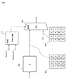
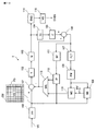
- FIG. 1 is a diagram showing a configuration of a moving picture encoding apparatus 1 according to the first embodiment.
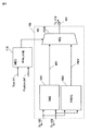
- FIG. 2 is a diagram for explaining operations of the quantization output adjustment unit 116 and the quantization output control unit 117 included in the moving picture coding apparatus 1 according to the first embodiment.
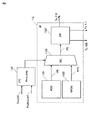
- FIG. 3 is a diagram for explaining the configuration and operation of the motion vector detection control unit 118 and the motion vector detection unit 109 included in the video encoding device 1 according to the first embodiment.
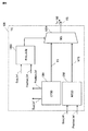
- FIG. 4 is a diagram for explaining the configuration and operation of the intra prediction control unit 119 and the intra prediction unit 112 included in the video encoding device 1 of the first embodiment.
- FIG. 5 is a diagram for explaining the configuration and operation of the frequency conversion control unit 120 included in the video encoding device 1 of the first embodiment.
- FIG. 6 is a diagram illustrating the configuration and operation of the quantization parameter control unit 121 included in the video encoding device 1 according to the first embodiment.
- FIG. 7 is a diagram illustrating the configuration and operation of the filter unit 107 and the filter control unit 122 for realizing low power consumption in the deblocking filter in the video encoding device 1 according to the first embodiment.
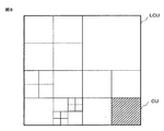
- FIG. 8 is a diagram illustrating how a coding unit (CU) is adaptively divided from a maximum coding unit (LCU).
- FIG. 9 is a diagram illustrating a configuration of a moving image encoding apparatus according to Embodiment 2 that executes parallel processing at a slice level or a tile level.
- FIG. 10 shows the current standard H.264 studied by the present inventors prior to the present invention.
- FIG. 2 is a diagram illustrating a configuration of a moving image encoding apparatus 1 that can generate an encoded bit stream by encoding a moving image input signal in accordance with a selected method of H.264 and the HEVC standard.
- FIG. 11 is a diagram for explaining the padding processing in the padding processing unit 100 of the moving image encoding apparatus 1 studied by the present inventors prior to the present invention shown in FIG.
- a moving picture encoding apparatus (1) performs a moving picture encoding process of syntax elements related to a moving picture signal (VS) to be encoded, thereby encoding bits.
- a stream (CVBS) is formed (see FIG. 1).
- the moving picture coding apparatus Prior to the moving picture coding process, the moving picture coding apparatus (1) executes a padding process (100) in which padding process data (PD) is added to the moving picture signal (VS).
- a padding process 100 in which padding process data (PD) is added to the moving picture signal (VS).
- the horizontal and vertical sizes of the additional moving image signal to which the padding processing data (PD) is added by the padding processing are set to integer multiples of the coding block size of the moving image coding processing.
- the moving picture coding apparatus (1) determines whether the coding block of the syntax element related to the moving picture signal belongs to the moving picture signal (VS) or the padding processing data (PD). Is done.
- the first code amount is set to The moving image encoding process is controlled according to the determination in the first case so that the encoded bit stream is formed.
- the first The moving image encoding process is controlled by the determination in the second case so that the encoded bit stream having the second code amount smaller than the code amount is formed.
- the moving picture encoding device (1) defined in [1] includes a padding processing unit, a motion vector detecting unit, a motion compensating unit, a subtracter, a frequency converting unit, and a quantizing unit.
- Unit an inverse quantization unit, an inverse frequency conversion unit, a memory (108, 111), an intra prediction unit, a selector unit, and a variable length coding unit.
- the padding processing unit (100) generates the additional moving image signal by executing the padding processing, and sends it to the subtracter (101), the motion vector detection unit (109), and the intra prediction unit (112). Supply.
- the motion vector detection unit (109) generates a motion vector (MV) from the additional moving image signal and the inter reference image stored in the memory (108).
- the motion compensation unit (110) is responsive to the motion vector (MV) generated from the motion vector detection unit (109) and the inter reference image stored in the memory (108). Is generated.
- the intra prediction unit (112) generates an intra prediction signal from the additional moving image signal and the intra reference image stored in the memory (111).
- the selector unit (113) outputs a selected prediction signal selected from the motion compensation prediction signal generated from the motion compensation unit (110) and the intra prediction signal generated from the intra prediction unit (112). To do.
- the additional moving image signal is supplied to one input terminal of the subtracter (101), and the selection prediction signal output from the selector unit (113) is supplied to the other input terminal of the subtracter (101). And a prediction residual is generated from the output terminal of the subtracter (101).
- the frequency conversion unit (102) and the quantization unit (103) perform frequency conversion processing and quantization processing, respectively.
- the result of the frequency conversion process of the frequency conversion unit (102) quantized by the quantization unit (103) is locally decoded by the inverse quantization unit (104) and the inverse frequency conversion unit (105). Processing is executed, and the result of the local decoding processing is stored in the memory (108, 111) as the inter reference image and the intra reference image.
- the result of the frequency conversion processing of the frequency conversion unit (102) quantized by the quantization unit (103) is encoded by the variable length encoding unit (114), and the variable length encoding unit
- the coded bitstream (CVBS) is generated from (114).
- the syntax element related to the moving image signal is at least one of the following information (A) to (D) (see FIG. 1).
- the video encoding device (1) defined in [2] includes an output terminal of the quantization unit (103) and the variable length encoding unit (114).
- a quantized output adjusting unit (116) connected between the input terminal of the dequantizing unit (104) and the input terminal of the inverse quantizing unit (104), and a quantized output control unit connected to the quantized output adjusting unit (116) (117).
- the quantization output control unit (117) performs the frequency conversion process of the frequency conversion unit (102) quantized by the quantization unit (103) which is the syntax element related to the moving image signal. It is determined whether the information belongs to the moving image signal (VS) or the padding processing data (PD).
- the quantized output adjustment unit (116) has a quantized output signal (201) generated by the quantizing process of the quantizing unit (103) and a data amount smaller than the quantized output signal (201).
- the adjustment signal (200) and the determination result generated from the quantization output control unit (117) are supplied.
- the quantization output adjustment unit (116) In response to the determination result of the quantization output control unit (117) that the information of the frequency conversion process belongs to the video signal (VS), the quantization output adjustment unit (116) The quantized output signal (201) generated from (103) is supplied to the input terminal of the variable length coding unit (114) and the input terminal of the inverse quantization unit (104).
- the quantization output adjustment unit (116) 200 is supplied to the input terminal of the variable length coding unit (114) and the input terminal of the inverse quantization unit (104) (see FIGS. 1 and 2).
- the moving picture encoding device (1) defined in [2] includes a motion vector detection control unit (118) connected to the motion vector detection unit (109). ).
- the motion vector detection unit (109) includes a motion vector search unit (1091), a prediction vector generation unit (1092), and a motion vector selector unit (1093).
- the motion vector search unit (1091) generates a search motion vector (MV) by performing a motion vector search operation on the encoded block included in the additional moving image signal and encoded by inter prediction.
- MV search motion vector
- the prediction vector generation unit (1092) includes a standard H.264 standard for the encoded block included in the additional moving image signal and encoded by inter prediction. H.264 or standard H.264 A motion vector prediction method defined in H.265 is executed to generate a prediction vector (PMV).
- PMV prediction vector
- the motion vector detection control unit (118) includes the encoded block encoded by inter prediction that is the syntax element included in the additional moving image signal and related to the moving image signal. It is determined whether the signal (VS) or the padding processing data (PD) belongs.
- the motion vector selector unit (1093) includes the search motion vector (MV) generated by the motion vector search unit (1091) and the prediction vector (PMV) generated by the prediction vector generation unit (1092). And a determination result generated from the motion vector detection control unit (118).
- the motion vector selector unit (1093) In response to the determination result of the motion vector detection control unit (118) that the encoded block encoded by the inter prediction belongs to the video signal (VS), the motion vector selector unit (1093) The search motion vector (MV) generated by the motion vector search unit (1091) is supplied to the motion compensation unit (110) as the motion vector (MV).
- the motion vector selector unit is generated by the prediction vector generation unit
- the prediction vector (PMV) is supplied to the motion compensation unit (110) as the motion vector (MV) (see FIGS. 1 and 3).
- the video encoding device (1) defined in [2] further includes an intra prediction control unit (119) connected to the intra prediction unit (112). To do.
- the intra prediction unit (112) includes an intra prediction direction determination unit (1121), a neighborhood prediction direction generation unit (1122), a prediction direction selector unit (1123), and an intra prediction processing unit (1124).
- the intra prediction direction determination unit (1121) performs an intra prediction operation on the encoded block included in the additional moving image signal and encoded by intra prediction to generate a prediction direction (PD).
- the neighborhood prediction direction generation unit (1122) includes a standard H.264 standard for the encoded block included in the additional moving image signal and encoded by intra prediction. H.264 or standard H.264
- the near direction prediction method defined in H.265 is executed to generate a near direction prediction (NPD).
- the intra prediction control unit (119) includes the encoded block that is encoded by intra prediction that is the syntax element included in the additional moving image signal and is related to the moving image signal. It is determined whether it belongs to (VS) or the padding processing data (PD).
- the prediction direction selector unit (1123) includes the prediction direction (PD) generated by the intra prediction direction determination unit (1121) and the vicinity prediction direction (1122) generated by the vicinity prediction direction generation unit (1122). NPD) and a determination result generated from the intra prediction control unit (119).
- the prediction direction selector unit (1123) In response to a determination result of the intra prediction control unit (119) that the encoded block encoded by the intra prediction belongs to the video signal (VS), the prediction direction selector unit (1123) The prediction direction (PD) generated by the intra prediction direction determination unit (1121) is supplied to the intra prediction processing unit (1124).
- the intra prediction processing unit (1124) includes the selector unit (113) based on the prediction direction (PD) generated by the intra prediction direction determination unit (1121) and the intra reference image stored in the memory (111).
- the intra prediction signal to be supplied to is generated.
- the prediction direction selector unit (1123) In response to the determination result of the intra prediction control unit (119) that the encoded block encoded by the intra prediction belongs to the padding process data (PD), the prediction direction selector unit (1123) The neighborhood prediction direction (NPD) generated by the neighborhood prediction direction generation unit (1122) is supplied to the intra prediction processing unit (1124).
- the intra prediction signal supplied to the selector unit (113) is generated from a reference image (see FIGS. 1 and 4).
- the video encoding device (1) defined in [3] includes a frequency conversion control unit (120) connected to the frequency conversion unit (102). In addition.
- the frequency conversion control unit (120) sets a frequency conversion size (TS) for the frequency conversion process executed by the frequency conversion unit (102).
- an encoded block processed by the frequency conversion process executed by the frequency conversion unit includes the moving image signal and the padding processing data.
- the partition operation of the coded block in the frequency conversion unit (102) is determined (see FIGS. 1 and 5).
- the frequency conversion control unit (120) is a frequency conversion size determination unit (1201).
- the frequency conversion size determination unit (1201) is a standard H.264 standard. H.264 or standard H.264
- One selected frequency transform size (TS) is selected from a plurality of types of frequency transform size (TS) candidates defined in H.265 and supplied to one input terminal of the frequency transform size selector unit (1204).
- the region determination unit (1203) determines whether or not a coding block having the one selected frequency transform size (TS) crosses over a boundary between the moving image signal and the padding processing data.
- the non-crossover frequency transform size determining unit (1202) is configured to perform non-crossover frequency transform so that an encoded block processed by the frequency transform processing does not cross over the boundary between the moving image signal and the padding processing data.
- a size (NTS) is generated and supplied to the other input terminal of the frequency conversion size selector unit (1204).
- the frequency transform size selector unit In response to the determination result of the region determining unit (1203) that the encoded block having the one selected frequency transform size does not cross over the boundary, the frequency transform size selector unit (1204) The selected frequency conversion size is supplied to the frequency conversion unit (102) as the frequency conversion size (TS) for the frequency conversion processing.
- the frequency conversion size selector unit sets the non-crossover frequency conversion size to the frequency.
- the frequency conversion unit supplies the frequency conversion size to the frequency conversion unit (see FIGS. 1 and 5).
- the moving picture encoding device (1) defined in [2] includes a quantization parameter control unit (121) connected to the quantization unit (103). Is further provided.
- the quantization parameter control unit (121) includes a quantization parameter generation unit (1211), a quantization parameter register unit (1212), a region determination unit (1213), and a quantization parameter selector unit (1214).
- the quantization parameter generation unit (1211) generates a quantization parameter (QP) corresponding to a code amount of the coded bit stream (CVBS) generated from the variable length coding unit (114), and The data is supplied to one input terminal of the quantization parameter selector unit (1214) and the input terminal of the quantization parameter register unit (1212).
- QP quantization parameter
- the quantization parameter (QP) generated at the output terminal of the quantization parameter register unit (1212) is supplied to the other input terminal of the quantization parameter selector unit (1214).
- the region determination unit (1213) includes a coding block quantized by the quantization unit (103) that is the syntax element related to the moving image signal, the moving image signal (VS) and the padding It is determined to which of the processing data (PD) it belongs.
- the quantization parameter selector unit (1214) supplies the quantization parameter (QP) supplied from the quantization parameter generation unit (1211) to the one input terminal to the quantization unit (103).
- the quantization parameter selector unit In response to a determination result of the region determination unit that the coding block quantized by the quantization unit belongs to the padding processing data (PD), the quantization parameter selector unit is configured to store the quantization parameter register.
- the quantization parameter (QP) supplied from the output terminal of the unit (1212) to the other input terminal is supplied to the quantization unit (103) (see FIGS. 1 and 6).
- the video encoding device (1) defined in any one of [2] to [8] includes a filter connected to the memory (108).
- a unit (107) and a filter controller (122) are further provided.
- the filter unit (107) performs a deblocking filter process on the result of the local decoding process performed by the inverse quantization unit (104) and the inverse frequency transform unit (105), and the deblocking filter
- the result of the processing is stored in the memory (108).
- the filter control unit (122) is configured such that the result of the local decoding process in which the deblocking filter process is performed by the filter unit (107) is a result of the video signal (VS) and the padding process data (PD). It is determined to which one it belongs.
- the motion vector detection unit, the motion compensation unit, and the subtraction are one semiconductor integrated circuit. Integrated on a chip (see FIG. 1).
- the encoding block of the video encoding process The size is either a macroblock having a size of 16 pixels ⁇ 16 pixels or a coding unit that can be formed from a maximum coding unit having a size of 64 pixels ⁇ 64 pixels (see FIG. 1).
- the video encoding device (1) defined in any one of [2] to [8] is a standard H.264 standard. H.264 and standard H.264.
- the moving image encoding process of the moving image signal (VS) is executed to form the encoded bit stream (CVBS) (FIG. 1). reference).
- the moving picture encoding device defined in any one of [2] to [8] includes an image dividing unit (301) and a plurality of moving picture encodings. And processing units (1A, 1B, 1C, 1D).
- the image dividing unit (301) generates a plurality of divided moving image signals by dividing the moving image signal (VS).
- the plurality of divided moving image signals generated by the image dividing unit are processed in parallel by the plurality of moving image encoding processing units (1A, 1B, 1C, 1D).
- Each of the moving image encoding processing units of the plurality of moving image encoding processing units (1A, 1B, 1C, 1D) includes the motion vector detecting unit, the motion compensating unit, the subtractor, the frequency converting unit, and the quantum converting unit. And an inverse-frequency transform unit, an intra-prediction unit, a selector unit, and a variable-length coding unit (see FIG. 9).
- the image dividing unit (301) and the plurality of moving image encoding processing units (1A, 1B, 1C) 1D) is characterized by being integrated on one semiconductor chip of a semiconductor integrated circuit (see FIG. 9).
- An embodiment according to another aspect is a moving image that forms a coded bitstream (CVBS) by executing a moving picture coding process of syntax elements related to a moving picture signal (VS) to be coded.
- CVBS coded bitstream
- VS moving picture signal
- the moving picture coding apparatus Prior to the moving picture coding process, the moving picture coding apparatus (1) executes a padding process (100) in which padding process data (PD) is added to the moving picture signal (VS).
- a padding process 100 in which padding process data (PD) is added to the moving picture signal (VS).
- the horizontal and vertical sizes of the additional moving image signal to which the padding processing data (PD) is added by the padding processing are set to integer multiples of the coding block size of the moving image coding processing.
- the moving picture coding apparatus (1) determines whether the coding block of the syntax element related to the moving picture signal belongs to the moving picture signal (VS) or the padding processing data (PD). Is done.
- the first code amount is set to The moving image encoding process is controlled according to the determination in the first case so that the encoded bit stream is formed.
- the first The moving image encoding process is controlled by the determination in the second case so that the encoded bit stream having the second code amount smaller than the code amount is formed.
- FIG. 1 is a diagram showing a configuration of a moving picture encoding apparatus 1 according to the first embodiment.
- the moving picture encoding apparatus 1 is the same as the moving picture encoding apparatus 1 shown in FIG. H.264 and the HEVC standard can be used to generate a coded bitstream by coding a moving image input signal in accordance with any method selected.
- the moving image encoding apparatus 1 includes a padding processing unit 100, a subtracter 101, a frequency conversion unit 102, a quantization unit 103, an inverse quantization unit 104, an inverse frequency conversion unit 105, an adder 106, and a variable length. It comprises an encoding unit 114 and a video buffer 115. Furthermore, the moving image encoding apparatus 1 includes a filter unit 107, a frame memory 108, a motion vector detection unit 109, a motion compensation unit 110, a buffer memory 111, an intra prediction unit 112, and a selector unit 113.
- the moving image coding apparatus 1 includes a quantization output adjustment unit 116 and a quantization output that are not included in the moving image coding apparatus 1 illustrated in FIG.
- the control unit 117, the motion vector detection control unit 118, the intra prediction control unit 119, the frequency conversion control unit 120, and the quantization parameter control unit 121 are configured.
- the moving picture encoding apparatus 1 according to the first embodiment includes a filter control unit 122 that controls the deblocking filter of the filter unit 107 in order to realize low power consumption.
- the moving picture coding apparatus 1 forms a coded bitstream CVBS by executing a moving picture coding process of syntax elements related to a moving picture signal VS to be coded. is there.
- the moving picture encoding apparatus 1 executes a padding process in which padding process data PD is added to the moving picture signal VS.
- the horizontal and vertical sizes of the additional moving image signal to which the padding processing data PD has been added by the padding processing are set to integer multiples of the coding block size of the moving image coding processing.
- the moving picture coding apparatus 1 determines whether the coding block of the syntax element related to the moving picture signal VS belongs to the moving picture signal VS or the padding processing data PD.
- the first The moving image encoding process is controlled by the determination in the first case so that the encoded bit stream CVBS having a code amount is formed.
- the first example of the syntax element related to the video signal VS to be encoded is the frequency conversion of the frequency conversion unit 102 quantized by the quantization unit 103 Processing information.
- a second example of a syntax element related to the moving image signal VS to be encoded is information on a coding block encoded by inter prediction using a motion vector and a motion compensated prediction signal.
- a third example of the syntax element related to the moving image signal VS to be encoded is information on a coding block encoded by intra prediction using an intra reference image.
- a fourth example of the syntax element related to the moving image signal VS to be encoded is information on a coding block that is quantized by the quantization unit 103.
- the frequency conversion processing information of the frequency conversion unit 102 quantized by the quantization unit 103 is supplied to the input terminal of the quantization output adjustment unit 116.
- the coding block inter-coded by the motion compensation unit 110 using the motion vector MV formed from the motion vector detection unit 109 is either the moving image signal VS or the padding processing data PD.
- the motion vector detection unit 109 itself controls the partition operation of the encoded block in the motion vector detection unit 109 so as to include only one of them.
- intra prediction is performed so that a coding block that is intra-coded by the intra prediction unit 112 using the intra prediction direction includes only one of the video signal VS and the padding processing data PD.
- the partition operation of the encoded block in the unit 112 is controlled by the intra prediction unit 112 itself.
- the quantization unit 103 when the quantization unit 103 quantizes the frequency conversion coefficient of the frequency conversion unit 102, the frequency conversion coefficient that is a coding block is either the moving image signal VS or the padding processing data PD.
- the quantization unit 103 itself controls the partition operation of the coding block in the quantization unit 103 so as to include only one of them.
- At least one of the first to fourth examples described above is selected and executed, so that in the padding process, the code of the encoded bitstream CVBS It becomes possible to reduce the increase in the amount.
- the moving picture encoding apparatus 1 according to the first embodiment, at least a plurality of the first example to the fourth example described above are selected and executed, so that in the padding process, the encoded bit stream CVBS is selected. It is possible to further reduce the increase in the amount of codes.
- the amount of code of the encoded bitstream CVBS during the padding process can be greatly reduced.
- the local decoding processing result which is an encoded block subjected to the deblocking filter processing by the filter unit 107, is converted into the video signal VS.
- the partition operation of the encoded block in the filter unit 107 is controlled by the filter unit 107 itself so as to include only one of the padding processing data PD.
- FIG. 2 is a diagram for explaining operations of the quantization output adjustment unit 116 and the quantization output control unit 117 included in the moving picture coding apparatus 1 according to the first embodiment.
- the coding unit (CU) of the moving image signal VS to which the padding processing data PD is added is supplied to one input terminal of the subtractor 101, and the motion compensated prediction signal from the motion compensation unit 110 or
- the intra prediction information from the intra prediction unit 12 is supplied to the other input terminal of the subtractor 101 via the selector unit 113, so that a prediction residual is generated from the output terminal of the subtractor 101.
- the frequency conversion unit 102 and the quantization unit 103 perform frequency conversion processing and quantization processing, respectively.
- the quantized frequency conversion coefficient 201 of the frequency conversion unit 102 is generated from the output terminal of the quantization unit 103.
- the frequency transform unit 102 performs integer-based discrete cosine transform (DCT: Discrete Cosine Transform) or discrete sine transform (DST: Discrete Sine Transform) that outputs only integer transform coefficients that do not include decimals.
- DCT Discrete Cosine Transform
- DST discrete sine transform
- the frequency conversion coefficient 201 shown in FIG. 2 includes three integer non-zero coefficients (“5”, “ ⁇ 1”, “2”) and thirteen zero coefficients (“0”). Yes.
- the frequency conversion coefficient 201 is supplied to one input terminal of the quantization output adjustment unit 116 configured by the selector SEL.
- 16 zeros are connected to the other input terminal of the quantization output adjustment unit 116 configured by the selector SEL so that the encoded bit stream CVBS having a small code amount is generated from the variable length encoding unit 114.
- An adjusted frequency conversion coefficient 200 including a coefficient (“0”) is supplied.
- the output terminal of the quantization output control unit 117 is connected to the selection control terminal of the quantization output adjustment unit 116 constituted by the selector SEL.
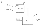
- Size information Size_Inf indicating the horizontal and vertical pixel sizes of the coding unit (CU) supplied to one input terminal of the subtractor 101 is supplied to one input terminal of the quantization output control unit 117, while the subtractor Position information Position_Inf of the coding unit (CU) supplied to one input terminal 101 is supplied to the other input terminal of the quantization output control unit 117.
- This position information Position_Inf is the raster scan start address (X, Y) at the upper left of the coding unit (CU).
- FIG. 8 is a diagram illustrating a state where the coding unit (CU) is adaptively divided from the maximum coding unit (LCU). Therefore, at least one of the raster scan start address at the upper left of the maximum coding unit (LCU) and the raster scan start address at the upper left of the coding unit (CU) inside the maximum coding unit (LCU) is quantized as position information Position_Inf. It is supplied to the output control unit 117.
- the quantization output control unit 117 is supplied with the size information Size_Inf and the position information Position_Inf of the coding unit (CU), and the coding unit (CU) belongs to either the moving image signal VS or the padding processing data PD. Is determined.
- the quantization output control unit 117 determines that the coding unit (CU) belongs to the video signal VS, for example, a high-level “1” selection output signal is generated from the output terminal of the quantization output control unit 117.
- the quantization output adjustment unit 116 is supplied to one input terminal in response to the high level “1” selection output signal generated from the output terminal of the quantization output control unit 117.
- the frequency conversion coefficient 201 including 13 non-zero coefficients and 13 zero coefficients is selected and output to the output terminal. Therefore, the frequency transform coefficient 201 including three non-zero coefficients and thirteen zero coefficients output to the output terminal of the quantization output adjustment unit 116 is the same as the input terminal of the variable length coding unit 114 and the inverse quantization unit.
- variable length coding unit 114 forms a coded bitstream CVBS having a relatively large code amount as the first code amount. Therefore, in this case, the video decoding device (Video Decoder) to which the encoded bit stream CVBS is supplied can reproduce the video signal VS with high image quality.
- the quantization output control unit 117 determines that the coding unit (CU) belongs to the padding process data PD, for example, a low level “0” selection output signal is output from the output terminal of the quantization output control unit 117. Generated. As a result, the quantization output adjustment unit 116 responds to the low level “0” selection output signal generated from the output terminal of the quantization output control unit 117, and supplies the 16 output signals supplied to the other input terminal. The adjustment frequency conversion coefficient 200 including the zero coefficient is selected and output to the output terminal.
- the adjusted frequency transform coefficient 200 including 16 zero coefficients output to the output terminal of the quantization output adjustment unit 116 is supplied to the input terminal of the variable length encoding unit 114 and the input terminal of the inverse quantization unit 104. Is done.
- the variable length coding unit 114 forms a coded bitstream CVBS having a second code amount smaller than the first code amount. Therefore, in this case, it is possible to reduce an increase in the code amount of the encoded bitstream CVBS by the padding process of the padding processing unit 100.
- the encoded bit stream CVBS is stored on a recording disk having a certain video storage capacity such as a nonvolatile memory or a DVD, the saved amount and the recording time can be lengthened, or the saved amount can be improved. It becomes possible.
- the frequency conversion coefficient 201 or the adjusted frequency conversion coefficient 200 output to the output terminal of the quantization output adjustment unit 116 is: This is supplied to the input terminal of the variable length coding unit 114 and the input terminal of the inverse quantization unit 104. Therefore, a moving picture decoding apparatus (Video decoder) to which a result of local decoding executed by the inverse quantization unit 104, the inverse frequency conversion unit 105, the adder 106, the filter unit 107, and the frame memory 108 and the encoded bit stream CVBS is supplied It is possible to prevent a mismatch between the reproduced image of Decoder).
- Video decoder Video decoder
- the moving image encoding apparatus 1 includes a quantization output adjusting unit 116, an output terminal of the quantization unit 103, an input terminal of the variable length encoding unit 114, and an inverse quantum. Connected to the input terminal of the conversion unit 104.
- two quantization output adjustment units 116 are used, and the first quantization output adjustment unit 116 is provided between the output terminal of the quantization unit 103 and the input terminal of the variable length encoding unit 114. It is also possible to connect the second quantization output adjustment unit 116 between the output terminal of the quantization unit 103 and the input terminal of the inverse quantization unit 104.
- a single quantization output control unit 117 controls the first quantization output adjustment unit 116 and the second quantization output adjustment unit 116 in common, and the coding unit (CU) pads the video signal VS and padding. It is possible to determine to which of the processing data PD belongs. Also in this other embodiment, it is possible to reduce an increase in the code amount of the encoded bitstream CVBS due to the padding processing of the padding processing unit 100, and the above-mentioned local decoding processing result and moving picture decoding apparatus described above It is possible to prevent the occurrence of mismatch with the reproduced image.
- the moving picture encoding apparatus 1 of the first embodiment is the current standard H.264.
- a coded bit stream CVBS is generated by encoding a moving image input signal in accordance with H.264
- a macroblock having a luminance component size of 16 pixels ⁇ 16 pixels instead of the above-described coding unit (CU).
- MB is to be processed.
- the frequency conversion coefficient 201, the adjustment frequency conversion coefficient 200, and the like are output from the output terminal of the quantization output adjustment unit 116. Is output.
- FIG. 3 is a diagram for explaining the configuration and operation of the motion vector detection control unit 118 and the motion vector detection unit 109 included in the video encoding device 1 according to the first embodiment.
- the motion vector detection unit 109 includes a motion vector search unit 1091, a prediction vector generation unit 1092, and a motion vector selector unit 1093.
- the motion vector search unit 1091 generates a motion vector MV by executing a general motion vector search operation according to the MPEG-2 and MPEG-4 standards, and the generated motion vector MV is the motion vector selector 1093. It is supplied to one input terminal.
- a general motion vector search operation executed by the motion vector search unit 1091 is performed by inter prediction with reference to a motion vector MV of a coding unit (CU) in the vicinity of a coding unit (CU) encoded by inter prediction.
- the motion vector MV of the coding unit (CU) to be converted is searched and generated.
- Prediction vector generation unit 1092 is the current standard H.264.
- the prediction vector PMV is generated by executing a prediction method defined by H.264 and the HEVC standard, and the generated prediction vector PMV is supplied to the other input terminal of the motion vector selector unit 1093.
- a motion vector candidate list that can be a prediction value is generated for a coding unit (CU) encoded by inter prediction, and a motion vector candidate list is encoded from the motion vectors included in the list.
- a method is adopted in which the optimal prediction candidate is selected by the conversion side, and the index of the optimal prediction candidate is encoded and transmitted to the decoding side.
- the motion vector MV can be encoded by selecting the prediction vector PMV as the prediction value with the smallest prediction difference.
- the other input terminal of the motion vector detection control unit 118 is supplied with position information Position_Inf of the macroblock (MB) or coding unit (CU) encoded by inter prediction.
- Position_Inf is the raster scan start address (X, Y) at the upper left of the macroblock (MB) or coding unit (CU).
- the motion vector detection control unit 118 is supplied with the size information Size_Inf and the position information Position_Inf of the macroblock (MB) or the coding unit (CU), and the macroblock (MB) or the coding unit (CU) is the moving image. It is determined whether the signal VS or the padding processing data PD belongs.
- the motion vector selector unit 1093 is supplied from the motion vector search unit 1091 to one of its input terminals in response to a high level “1” selection output signal generated from the output terminal of the motion vector detection control unit 118.
- Motion vector MV to be selected and output to its output terminal.
- the motion vector MV generated from the motion vector search unit 1091 of the motion vector detection unit 109 is supplied to the motion compensation unit 110 via the motion vector selector unit 1093.
- the motion compensation unit 110 in response to the motion vector MV generated from the motion vector search unit 1091 of the motion vector detection unit 109 and the reference image stored in the frame memory 108, the motion compensation unit 110 generates a motion compensated prediction signal.
- the variable length encoding unit 114 encodes a difference vector (MVD: Motion Vector Difference) which is ⁇ PMV).
- the moving picture decoding apparatus to which the encoded bit stream CVBS is supplied can obtain the difference vector related to the moving picture signal VS.
- the variable length coding unit 114 has a coded bit stream having a relatively large code amount as the first code amount. CVBS is formed.
- the moving picture decoding apparatus to which the encoded bit stream CVBS having a relatively large code amount is supplied can reproduce the moving picture signal VS with high image quality.
- the motion vector selector unit 1093 responds to the generated low level “0” selection output signal, and the prediction vector PMV supplied from the prediction vector generation unit 1092 of the motion vector detection unit 109 to the other input terminal. Select and output to the output terminal. Therefore, in the case of inter prediction of the padding process data PD, the prediction vector PMV generated from the prediction vector generation unit 1092 is output from the motion vector selector unit 1093 of the motion vector detection unit 109.
- the prediction vector PMV as the motion vector MV generated from the motion vector selector 1093 of the motion vector detection unit 109 and the prediction vector PMV generated from the prediction vector generation unit 1092 of the motion vector detection unit 109 The difference vector (MVD) which is the difference (MV ⁇ PMV) is substantially zero.
- the variable length coding unit 114 codes the difference vector (MVD) having a value of substantially zero.
- the variable length encoding unit 114 in response to the difference vector (MVD) having a value of substantially zero, the variable length encoding unit 114 generates an encoded bitstream CVBS having a second code amount smaller than the first code amount.
- the information of the padding processing data PD encoded by the variable length encoding unit 114 greatly affects the image quality of the moving image signal VS reproduced by the moving image decoding device. is not. Therefore, in this case, it is possible to reduce an increase in the code amount of the encoded bitstream CVBS due to the padding processing of the padding processing unit 100.
- the encoded bit stream CVBS is stored in a recording disk having a certain video storage capacity, it is possible to lengthen the saving time and the recording time, or to improve the image quality by the saving amount.
- FIG. 4 is a diagram for explaining the configuration and operation of the intra prediction control unit 119 and the intra prediction unit 112 included in the video encoding device 1 of the first embodiment.
- the intra prediction unit 112 includes an intra prediction direction determination unit 1121, a neighborhood prediction direction generation unit 1122, a prediction direction selector unit 1123, and an intra prediction processing unit 1124.
- Intra prediction direction determination unit 1121 is MPEG-4, H.264, etc. H.264, H.H.
- a prediction direction PD is generated by executing a general intra prediction operation according to the H.265 standard, and the generated prediction direction PD is supplied to one input terminal of the prediction direction selector unit 1123.
- a general intra prediction operation executed by the intra prediction direction determination unit 1121 is as follows. That is, in MPEG-4, there are two prediction directions PD, the horizontal direction and the vertical direction. H. In H.264, the prediction directions PD of nine directions described in Non-Patent Document 1 are described, and in the HEVC standard, the prediction directions PD of 34 modes described in Non-Patent Document 2 are described.
- the neighborhood prediction direction generation unit 1122 is similar to the prediction vector generation unit 1092 described in FIG.
- the prediction method defined by H.264 and the HEVC standard is executed to generate a neighborhood prediction direction NPD, and the generated neighborhood prediction direction NPD is supplied to the other input terminal of the prediction direction selector unit 1123.
- the other input terminal of the intra prediction control unit 119 is supplied with position information Position_Inf of the macroblock (MB) or coding unit (CU) encoded by the intra prediction.
- Position_Inf is the raster scan start address (X, Y) at the upper left of the macroblock (MB) or coding unit (CU).
- the size information Size_Inf and the position information Position_Inf of the macro block (MB) or the coding unit (CU) are supplied to the intra prediction control unit 119, and the macro block (MB) or the coding unit (CU) receives the video signal. It is determined whether the data belongs to VS or padding processing data PD.
- the intra prediction control unit 119 determines that a macroblock (MB) or coding unit (CU) encoded by intra prediction belongs to the moving image signal VS, for example, a high-level “1” selection output signal is output. It is generated from the output terminal of the intra prediction control unit 119. Therefore, the prediction direction selector unit 1123 is supplied from the intra prediction direction determination unit 1121 to one of its input terminals in response to the selection output signal of high level “1” generated from the output terminal of the intra prediction control unit 119. Predictive direction PD to be output to the output terminal. As a result, the prediction direction PD generated from the intra prediction direction determination unit 1121 is supplied to the intra prediction processing unit 1124 via the prediction direction selector unit 1123.
- MB macroblock
- CU coding unit
- the intra prediction processing unit 1124 is supplied with the coding unit (CU) of the moving image signal VS to which the padding processing data PD is added from the padding processing unit 100 and the intra-coded reference image from the buffer memory 111. Accordingly, the intra prediction processing unit 1124 uses the prediction direction PD, the coding unit (CU), and the intra-encoded reference image to supply the selector unit 113 with the optimal intra-predicted coding unit (CU). In the case of this intra prediction, the difference (PD) between the prediction direction PD generated from the prediction direction selector unit 1123 of the intra prediction unit 112 and the near prediction direction NPD generated from the near prediction direction generation unit 1122 of the intra prediction unit 112.
- the variable length encoding unit 114 encodes a difference prediction direction (PDD: Prediction Direction Difference) which is ⁇ NPD). Since the encoded information by the variable length encoding unit 114 in the difference prediction direction (PDD) is included in the encoded bit stream CVBS, the moving picture decoding apparatus to which the encoded bit stream CVBS is supplied is the difference regarding the moving picture signal VS. By decoding the information of the prediction direction (PDD), the moving image signal VS can be reproduced. Thus, in the case of intra prediction of the video signal VS, in response to the difference prediction direction (PDD), the variable length coding unit 114 has coded bits having a relatively large code amount as the first code amount. A stream CVBS is formed. As a result, the moving picture decoding apparatus to which the encoded bit stream CVBS having a relatively large code amount is supplied can reproduce the moving picture signal VS with high image quality.
- PDD Prediction Direction Difference
- the prediction direction selector unit 1123 responds to the generated low level “0” selection output signal, and the neighborhood prediction direction supplied from the neighborhood prediction direction generation unit 1122 of the intra prediction control unit 119 to the other input terminal. Select NPD and output to its output terminal. Therefore, in the case of intra prediction of the padding process data PD, the neighborhood prediction direction NPD generated from the neighborhood prediction direction generation unit 1122 is output from the prediction direction selector unit 1123 of the intra prediction unit 112.
- the neighborhood prediction direction NPD as the prediction direction PD generated by the prediction direction selector unit 1123 of the intra prediction unit 112 and the neighborhood prediction direction NPD generated from the neighborhood prediction direction generation unit 1122 of the intra prediction unit 112 The difference prediction direction (PDD), which is the difference (PD ⁇ NPD), is substantially zero.
- the variable length encoding unit 114 encodes the differential prediction direction (PDD) having a value of substantially zero.
- the variable length encoding unit 114 has an encoded bitstream CVBS having a second code amount smaller than the first code amount.
- the information of the padding processing data PD encoded by the variable length encoding unit 114 greatly affects the image quality of the moving image signal VS reproduced by the moving image decoding device. is not. Therefore, in this case, it is possible to reduce an increase in the code amount of the encoded bitstream CVBS due to the padding processing of the padding processing unit 100.
- the encoded bit stream CVBS is stored in a recording disk having a certain video storage capacity, it is possible to lengthen the saving time and the recording time, or to improve the image quality by the saving amount.
- FIG. 5 is a diagram for explaining the configuration and operation of the frequency conversion control unit 120 included in the video encoding device 1 of the first embodiment.
- one coding unit (CU) has a moving picture signal as shown in FIG. Assume that the pixel value of VS and the pixel value of padding processing data PD are included at the same time. As shown in FIG. 11, one coding unit (CU) including the pixel value of the moving image signal VS and the pixel value of the padding processing data PD simultaneously includes a region of the moving image signal VS and a region of the padding processing data PD. Exists at the boundary between.
- the quantization output adjustment unit 116 determines that it belongs to the moving image signal VS. As described above, the quantization output adjustment unit 116 operates. Therefore, with respect to one coding unit (CU) that simultaneously includes the pixel value of the moving image signal VS and the pixel value of the padding processing data PD, the variable length encoding unit 114 forms an encoded bit stream CVBS having a large code amount. To do.
- the moving image signal VS included in one coding unit (CU) that simultaneously includes the pixel value of the moving image signal VS and the pixel value of the padding processing data PD is converted into a high image quality by a moving image decoding device (Video Decoder). It can be played back with.
- a moving image decoding device Video Decoder
- H.C. In the case of H.264, even for one macroblock (MB) that simultaneously includes the pixel value of the moving image signal VS and the pixel value of the padding processing data PD, this one macroblock (MB) When it belongs to VS, it is necessary to determine mixing.
- this one macroblock (MB) or coding unit (CU) needs to be determined to belong to the moving image signal VS as well in the motion vector detection control unit 118 in FIG. 3 and the intra prediction control unit 119 in FIG.
- the same necessity is the same for the quantization parameter control unit 121 described below using FIG. 6 and the filter control unit 122 described below using FIG.
- the padding processing data PD included in one mixed coding unit (CU) or macroblock (MB) is also included in the filter unit 107. Since the function of the deblocking filter is activated, there may be a problem that the effect of reducing power consumption is reduced.
- the frequency conversion control unit 120 shown in FIG. 5 is configured such that one coding unit (CU) is a video signal VS in the frequency conversion process in the frequency conversion unit 102 included in the video encoding device 1 of the first embodiment.
- the partition operation is executed so as not to include the pixel value and the pixel value of the padding process data PD at the same time. That is, one coding unit (CU) includes only one of the pixel value of the moving image signal VS and the pixel value of the padding processing data PD by the partition operation of the coding unit (CU) in the frequency conversion unit 102. It will be a thing. In other words, one coding unit (CU) does not cross over the boundary between the moving image signal VS and the padding processing data PD. In other words, the boundary of one coding unit (CU) coincides with the boundary between the moving image signal VS and the padding processing data PD.
- the frequency conversion control unit 120 includes a frequency conversion size determination unit 1201, a non-crossover frequency conversion size determination unit 1202, a region determination unit 1203, and a frequency conversion size selector unit 1204.
- a size In the HEVC standard, in the frequency conversion of one coding unit (CU) that can be divided from one maximum coding unit (LCU) having a luminance component size of 64 pixels ⁇ 64 pixels, 32 pixels ⁇ 32 pixels are converted. There are four types of frequency conversion sizes that can be used: a size, a size of 16 pixels ⁇ 16 pixels, a size of 8 pixels ⁇ 8 pixels, and a size of 4 pixels ⁇ 4 pixels.
- One frequency conversion size TS is selected from two frequency conversion sizes of the H.264 standard or four frequency conversion sizes of the HEVC standard, and this one frequency conversion size TS is input to one of the frequency conversion size selector section 1204. Supply to the terminal.
- This one frequency transform size TS is determined, for example, at a timing when a motion compensated prediction signal is generated from the motion compensation unit 110 or at a timing when an intra prediction signal is generated from the intra prediction unit 112. That is, in the portion where the pixel value of the image signal of the motion compensation prediction signal or the intra prediction signal changes monotonously, the frequency conversion size determination unit 1201 selects the frequency conversion size TS as a relatively large size.
- the frequency conversion size determination unit 1201 selects the frequency conversion size TS as a relatively small size. Further, the frequency transform size determination unit 1201 determines the size information Size_Inf and the position information Position_Inf at the same time as determining the frequency transform size TS of one macroblock (MB) or one coding unit (CU). To do.
- the size information Size_Inf and the position information Position_Inf are supplied to the region determination unit 1203.
- one macroblock (MB) or one coding unit (CU) having the size information Size_Inf and the position information Position_Inf crosses the boundary between the moving image signal VS and the padding processing data PD. It is determined whether or not to do.
- the region determination unit 1203 When the determination result of the region determination unit 1203 is “NO”, the region determination unit 1203 generates a selection output signal of high level “1” and supplies it to the selection control signal of the frequency conversion size selector unit 1204.
- the frequency conversion size selector unit 1204 receives the frequency supplied from the frequency conversion size determination unit 1201 to one input terminal thereof. A conversion size TS is selected and output to its output terminal.
- the frequency conversion unit 102 included in the moving picture coding apparatus 1 according to Embodiment 1 performs frequency conversion of one coding unit (CU) or one macroblock (MB) 1 according to the frequency conversion size TS. Execute the process.
- the region determination unit 1203 when the determination result of the region determination unit 1203 is “YES”, the region determination unit 1203 generates a selection output signal of low level “0” and uses it as the selection control signal of the frequency transform size selector unit 1204. Supply.
- the frequency conversion size selector unit 1204 responds to the low level “0” selection output signal generated from the output terminal of the region determination unit 1203 to the non-crossover frequency conversion size determination unit 1202 at the other input terminal.
- the non-crossover frequency conversion size NTS supplied from is selected and output to its output terminal.
- the non-crossover frequency transform size determining unit 1202 responds to the size information Size_Inf and position information Position_Inf of one macroblock (MB) or one coding unit (CU) supplied from the frequency transform size determining unit 1201.
- the non-crossover frequency conversion size NTS is generated and supplied to the other input terminal of the frequency conversion size selector unit 1204.
- the frequency transform unit 102 included in the moving picture coding apparatus 1 performs one coding according to the non-crossover frequency transform size TS generated by the non-crossover frequency transform size determination unit 1202.
- the frequency conversion process of a unit (CU) or one macro block (MB) 1 is executed.
- FIG. 6 is a diagram illustrating the configuration and operation of the quantization parameter control unit 121 included in the video encoding device 1 according to the first embodiment.
- the quantization parameter control unit 121 includes a quantization parameter generation unit 1211, a quantization parameter register unit 1212, a region determination unit 1213, and a quantization parameter selector unit 1214.
- Control is executed by adjusting the quantization parameter QP used in the quantization process of the quantization unit 103.
- the quantization parameter control unit 121 connected to the quantization unit 103 performs adjustment control of the quantization parameter QP for bit rate control. Therefore, the quantization parameter generation unit 1211 uses the compressed video encoded bitstream CVBS generated from the variable length encoding unit 114 based on, for example, the data sufficiency of the video buffer 115 connected to the output of the variable length encoding unit 114. Grasp the amount of codes. When the code amount is large, the quantization parameter generation unit 1211 sets the quantization parameter QP to a large value.
- the quantization unit 103 reduces the number of bits of the frequency transform coefficient to be quantized, and thus the code amount of the compressed video encoded bit stream CVBS becomes excessive. It becomes possible to prevent.
- the quantization parameter generation unit 1211 sets the quantization parameter QP to a small value.
- the quantization unit 103 increases the number of bits of the frequency transform coefficient to be quantized, so that the code amount of the compressed video encoded bitstream CVBS can be increased. It is possible to generate a compressed video encoded bitstream CVBS with high image quality.
- the variable length coding unit 114 includes a differential quantization parameter (QPD: Quantization Parameter Difference which is a temporal change of the quantization parameter QP of the quantization unit 103. ) As a syntax element.
- QPD Quantization Parameter Difference
- the moving picture decoding apparatus (Decoder) also uses the differential quantization parameter ( It is possible to execute an accurate video decoding processing operation using QPD).
- the quantization unit 103 includes the pixel value of the moving image signal VS among the information to be quantized, which is necessary for the high-quality moving image decoding operation in the moving image decoding apparatus.
- the pixel value does not greatly affect the image quality of the moving image signal VS reproduced by the moving image decoding apparatus.
- the quantization parameter control unit 121 has the macroblock (MB) or coding unit (CU) quantized by the quantization unit 103 as the moving image signal VS and the padding data.
- An area determination unit 1213 for determining which of the PDs belongs to is included.
- the area determination unit 1213 is supplied with size information Size_Inf and position information Position_Inf of the macroblock (MB) or coding unit (CU) to be quantized by the quantization unit 103.
- a high-level “1” selection output signal is output from the region determination unit. 1213 is generated from the output terminal.
- the quantization parameter selector unit 1214 is supplied from the quantization parameter generation unit 1211 to one of its input terminals in response to the high-level “1” selection output signal generated from the output terminal of the region determination unit 1213.
- the quantization parameter QP to be selected is selected and output to its output terminal.
- the quantization unit 103 performs a quantization process on the frequency conversion coefficient by the frequency conversion unit 102 of the macroblock (MB) or coding unit (CU) belonging to the moving image signal VS. is there.
- the quantization parameter QP generated from the quantization parameter selector unit 1214 of the quantization parameter control unit 121 and the quantization immediately before being generated from the quantization parameter register unit 1212 and stored in the quantization parameter register unit 1212
- the variable length encoding unit 114 encodes a differential quantization parameter (QPD) that is a difference between parameters PQP (QP ⁇ PQP).
- the moving picture decoding apparatus to which the coded information by the variable length coding unit 114 of the difference quantization parameter (QPD) is included in the coded bit stream CVBS and the coded bit stream CVBS is supplied is the difference quantum for the moving picture signal VS.
- the variable length coding unit 114 performs coding having a relatively large code amount as the first code amount.
- a bit stream CVBS is formed.
- the low-level “0” selection output signal is a region. It is generated from the output terminal of the determination unit 1213.
- the quantization parameter selector unit 1214 supplies the other input terminal from the quantization parameter register unit 1212 in response to the low level “0” selection output signal generated from the output terminal of the region determination unit 1213.
- the quantization parameter PQP immediately before being selected is selected and output to its output terminal.
- the quantization unit 103 performs a quantization process on the frequency conversion coefficient by the frequency conversion unit 102 of the macroblock (MB) or coding unit (CU) belonging to the padding processing data PD.
- the quantization parameter QP generated from the quantization parameter selector unit 1214 of the quantization parameter control unit 121 and the previous quantization parameter stored in the quantization parameter register unit 1212 and generated from the prediction vector generation unit 1092
- the differential quantization parameter (QPD) that is the difference of PQP (QP ⁇ PQP) is substantially zero.
- the variable length encoding unit 114 encodes the differential quantization parameter (QPD) having a value of substantially zero.
- the variable-length encoding unit 114 in response to the differential quantization parameter (QPD) having a value of substantially zero, the variable-length encoding unit 114 has an encoded bitstream having a second code amount smaller than the first code amount.
- CVBS is formed.
- the information of the padding processing data PD encoded by the variable length encoding unit 114 greatly affects the image quality of the moving image signal VS reproduced by the moving image decoding device. is not.
- the encoded bit stream CVBS is stored in a recording disk having a certain video storage capacity, it is possible to lengthen the saving time and the recording time, or to improve the image quality by the saving amount.
- FIG. 7 is a diagram illustrating the configuration and operation of the filter unit 107 and the filter control unit 122 for realizing low power consumption in the deblocking filter in the video encoding device 1 according to the first embodiment. .
- the filter unit 107 included in the video encoding device 1 of the first embodiment is the H.264 standard. According to the H.264 standard, it has a function of a deblocking filter for reducing block distortion.
- the result of local decoding processing by the inverse quantization unit 104, the inverse frequency conversion unit 105, and the adder 106 is subjected to filter processing by the function of the deblocking filter of the filter unit 107.
- information filtered by the function of the deblocking filter of the filter unit 107 may belong to the moving image signal VS or to the padding processing data PD.
- the local decoding processing result belonging to the moving image signal VS is filtered by the function of the deblocking filter of the filter unit 107, so that block distortion of the reference image stored in the frame memory 108 and used for intra prediction is reduced. It becomes possible. However, even if the local decoding processing result belonging to the padding processing data PD is filtered by the filter unit 107, it is impossible to reduce the block distortion of the reference image stored in the frame memory 108 and used for intra prediction. .
- the filter unit 107 and the filter control unit 122 according to Embodiment 1 shown in FIG. 7 are configured so that when the deblocking filter processing target information supplied from the adder 106 to the filter unit 107 belongs to the moving image signal VS, The deblocking filter processing of this information is executed. However, when the deblocking filter processing target information supplied from the adder 106 to the filter unit 107 belongs to the padding processing data PD, the filter unit 107 and the filter control unit 122 according to Embodiment 1 shown in FIG. The execution of the deblocking filter processing of this information is stopped.
- the size information Size_Inf and the position information Position_Inf of the deblocking filter processing target information supplied from the adder 106 to the filter unit 107 are supplied to the filter control unit 122 shown in FIG.
- the filter control unit 122 determines that the deblocking filter processing target information belongs to the moving image signal VS, for example, a high level “1” operation selection signal is generated from the output terminal of the filter control unit 122. Accordingly, the function of the deblocking filter of the filter unit 107 is activated in response to the high level “1” operation output signal generated from the output terminal of the filter control unit 122. As a result, the function of the deblocking filter of the filter unit 107 executes a deblocking filter process for information belonging to the moving image signal VS.
- the filter control unit 122 determines that the deblocking filter processing target information belongs to the padding processing data PD, for example, a low level “1” non-operation selection signal is generated from the output terminal of the filter control unit 122. Therefore, the function of the deblocking filter of the filter unit 107 is deactivated in response to the low level “1” non-operation selection signal generated from the output terminal of the filter control unit 122. As a result, the function of the deblocking filter of the filter unit 107 is to stop the execution of the deblocking filter process for the information belonging to the padding process data PD. In this way, according to the filter unit 107 and the filter control unit 122 according to Embodiment 1 shown in FIG. 7, it is possible to reduce the power consumption of the deblocking filter.
- ⁇ Semiconductor integrated circuit of moving picture coding apparatus Most of the moving picture coding apparatus 1 according to the first embodiment is integrated in one semiconductor chip of a semiconductor integrated circuit except for the frame memory 108, the buffer memory 111, and the video buffer 115.
- this semiconductor integrated circuit is a large-scale semiconductor integrated circuit called a system LSI or system on chip (SOC) manufactured by a state-of-the-art semiconductor manufacturing process.
- the padding processing unit 100, the subtractor 101, the frequency conversion unit 102, the quantization unit 103, the inverse quantization unit 104, the inverse frequency conversion unit 105, and the adder 106 The variable length encoding unit 114 is integrated on one semiconductor chip of the semiconductor integrated circuit. Further, the filter unit 107, the frame memory 108, the motion vector detection unit 109, the motion compensation unit 110, the buffer memory 111, the intra prediction unit 112, and the selector unit 113 are also integrated on this one semiconductor chip.
- the quantization output adjustment unit 116, the quantization output control unit 117, the motion vector detection control unit 118, the intra prediction control unit 119, the frequency conversion control unit 120, the quantization parameter control unit 121, and the filter control unit 122 are also the same. Further, it is integrated in this single semiconductor chip.
- the frame memory 108, the buffer memory 111, and the video buffer 115 are integrated on a semiconductor chip of this single semiconductor chip and another synchronous dynamic random access memory (SDRAM).
- SDRAM synchronous dynamic random access memory
- FIG. 9 is a diagram illustrating a configuration of a moving image encoding apparatus according to Embodiment 2 that executes parallel processing at a slice level or a tile level.
- the slice is encoded and decoded independently of the other slices of the picture, so that the slice can be used for parallel processing.
- tiles can be processed in parallel, and tiles are formed by dividing a picture into rectangular areas.
- the moving picture coding apparatus includes an image dividing unit 301, an image construction unit 302, and a plurality of moving picture coding processing units 1A, 1B, 1C, and 1D. .. And the frame memory 108 and the buffer memory 111.
- the image dividing unit 301 is supplied with the moving image signal VS, and generates a plurality of slices or a plurality of tiles by dividing it.
- the plurality of slices or the plurality of tiles generated by the image dividing unit 301 are respectively supplied to the plurality of moving image encoding processing units 1A, 1B, 1C, and 1D.
- each moving image encoding processing unit includes a padding processing unit 100, a subtractor 101, a frequency conversion unit 102, a quantization unit 103, an inverse quantization unit 104, an inverse frequency conversion unit 105, an adder 106, and variable length encoding. Part 114. Further, each moving image encoding processing unit includes a motion vector detection unit 109, a motion compensation unit 110, a buffer memory 111, an intra prediction unit 112, and a selector unit 113.
- each moving image encoding processing unit includes a quantization output adjustment unit 116, a quantization output control unit 117, a motion vector detection control unit 118, an intra prediction control unit 119, a frequency conversion control unit 120, and a quantization parameter control unit. 121 and a filter control unit 122 are included.
- the plurality of moving image encoding processing results generated from the plurality of moving image encoding processing units 1A, 1B, 1C, and 1D are supplied to the image construction unit 302.
- the image construction unit 302 generates a compressed video encoded bit stream CVBS from a plurality of moving image encoding processing results of the plurality of moving image encoding processing units 1A, 1B, 1C, and 1D.
- Most of the moving picture coding apparatus according to the second embodiment is integrated in one semiconductor chip of a semiconductor integrated circuit except for the frame memory 108, the buffer memory 111, and the video buffer 115.
- This semiconductor integrated circuit is also a large-scale semiconductor integrated circuit called a system LSI or system on chip (SOC) manufactured by a state-of-the-art semiconductor manufacturing process.
- the main video encoding processing apparatus is the current standard H.264.
- the present invention is not limited to generating an encoded bit stream by encoding a moving image input signal in accordance with a selected method of H.264 and HEVC standards.
- the moving image encoding processing apparatus is not limited to the HEVC standard having a maximum coding unit (LCU) having a size of 64 ⁇ 64 pixels as a maximum processing unit, but also a maximum coding unit having a size larger than the size of 64 ⁇ 64 pixels.
- LCU maximum coding unit
- the present invention can also be applied to the generation of an encoded bit stream conforming to a standard that will appear in the future with (LCU) as the maximum processing unit.
- the quantization output control unit 117 in FIG. 2, the motion vector detection control unit 118 in FIG. 3, the intra prediction control unit 119 in FIG. 4, and the quantization parameter control unit 121 in FIG. Similar to the conversion control unit 120, it is possible to execute the partition operation so that one coding unit (CU) does not include the pixel value of the moving image signal VS and the pixel value of the padding processing data PD at the same time. As a result, it is possible to reduce the code amount of the encoded bit stream CVBS.
- one coding unit simultaneously converts the pixel value of the moving image signal VS and the pixel value of the padding processing data PD. It is possible to perform partition operations so that they are not included. As a result, it is possible to reduce the power consumption related to the function of the deblocking filter of the filter unit 107.
- the present invention can be widely applied to a moving picture coding apparatus and an operation method thereof that reduce an increase in the amount of code of a coded bitstream during padding processing.
Abstract
Description
先ず、本願において開示される発明の代表的な実施の形態について概要を説明する。代表的な実施の形態についての概要説明で括弧を付して参照する図面中の参照符号は、それが付された構成要素の概念に含まれるものを例示するに過ぎない。
(B).前記動きベクトルと前記動き補償予測信号とを使用して、インター予測によって符号化される符号化ブロックの情報、
(C).前記イントラ参照画像を使用してイントラ予測によって符号化される符号化ブロックの情報と、
(D).前記量子化部(103)で量子化処理される符号化ブロックの情報。
実施の形態について更に詳述する。なお、発明を実施するための形態を説明するための全図において、前記の図と同一の機能を有する要素には同一の符号を付して、その繰り返しの説明を省略する。
《動画像符号化装置の構成》
図1は、実施の形態1による動画像符号化装置1の構成を示す図である。
実施の形態1による動画像符号化装置1の概略は、下記の通りである。
以下に、実施の形態1による動画像符号化装置1の詳細を説明する。
図2は、実施の形態1の動画像符号化装置1に含まれる量子化出力調整部116と量子化出力制御部117の動作を説明する図である。
図3は、実施の形態1の動画像符号化装置1に含まれる動きベクトル検出制御部118と動きベクトル検出部109の構成と動作とを説明する図である。
図4は、実施の形態1の動画像符号化装置1に含まれるイントラ予測制御部119とイントラ予測部112の構成と動作とを説明する図である。
図5は、実施の形態1の動画像符号化装置1に含まれる周波数変換制御部120の構成と動作とを説明する図である。
図6は、実施の形態1の動画像符号化装置1に含まれる量子化パラメータ制御部121の構成と動作とを説明する図である。
図7は、実施の形態1の動画像符号化装置1において、デブロッキングフィルタでの低消費電力の実現のためのフィルタユニット107とフィルタ制御部122との構成と動作とを説明する図である。
実施の形態1の動画像符号化装置1の大部分は、フレームメモリ108とバッファメモリ111とビデオバッファ115を除き、半導体集積回路の1個の半導体チップ内に集積化される。例えば、この半導体集積回路は、最先端半導体製造プロセスによって製造されるシステムLSIもしくはシステムオンチップ(SOC)と呼ばれる大規模半導体集積回路である。
《並列処理を実行する動画像符号化装置の構成》
図9は、スライスレベルもしくはタイルレベルの並列処理を実行する実施の形態2による動画像符号化装置の構成を示す図である。
100…パディング処理部
101…減算器
102…周波数変換部
103…量子化部
104…逆量子化部
105…逆周波数変換部
106…加算器
107…フィルタユニット
108…フレームメモリ
109…動きベクトル検出部
110…動き補償部
111…バッファメモリ
112…イントラ予測部
113…セレクタ部
114…可変長符号化部
115…ビデオバッファ
116…量子化出力調整部
117…量子化出力制御部
118…動きベクトル検出制御部
119…イントラ予測制御部
120…周波数変換制御部
121…量子化パラメータ制御部
122…フィルタ制御部
Claims (20)
- 符号化すべき動画像信号に関係するシンタックスエレメントの動画像符号化処理を実行することによって、符号化ビットストリームを形成する動画像符号化装置であって、
前記動画像符号化処理に先行して、前記動画像信号にパディング処理データが追加されるパディング処理を前記動画像符号化装置が実行して、
前記パディング処理により前記パディング処理データが追加された追加動画像信号の横および縦のサイズは、前記動画像符号化処理の符号化ブロックサイズの整数倍に設定されるものであり、
前記動画像信号に関係する前記シンタックスエレメントの符号化ブロックが、前記動画像信号と前記パディング処理データとのいずれに属するかが前記動画像符号化装置により判定され、
前記動画像符号化装置の判定によって、前記動画像信号に関係する前記シンタックスエレメントの前記符号化ブロックが前記動画像信号に属すると判定される第1の場合には、第1の符号量を有する前記符号化ビットストリームが形成されるように、前記第1の場合の判定によって前記動画像符号化処理が制御され、
前記動画像符号化装置の他の判定によって、前記動画像信号に関係する前記シンタックスエレメントの前記符号化ブロックが前記パディング処理データに属すると判定される第2の場合には、前記第1の符号量よりも小さな第2の符号量を有する前記符号化ビットストリームが形成されるように、前記第2の場合の判定によって前記動画像符号化処理が制御される
動画像符号化装置。 - 請求項1において、
前記動画像符号化装置は、パディング処理部と動きベクトル検出部と動き補償部と減算器と周波数変換部と量子化部と逆量子化部と逆周波数変換部とメモリとイントラ予測部とセレクタ部と可変長符号化部とを具備して、
前記パディング処理部は、前記パディング処理を実行することによって前記追加動画像信号を生成して前記減算器と前記動きベクトル検出部と前記イントラ予測部に供給して、
前記動きベクトル検出部は、前記追加動画像信号と前記メモリに格納されたインター参照画像とから動きベクトルを生成して、
前記動き補償部は、前記動きベクトル検出部から生成される前記動きベクトルと前記メモリに格納された前記インター参照画像とに応答して動き補償予測信号を生成して、
前記イントラ予測部は、前記追加動画像信号と前記メモリに格納されたイントラ参照画像とからイントラ予測信号を生成して、
前記セレクタ部は、前記動き補償部から生成される前記動き補償予測信号と前記イントラ予測部から生成される前記イントラ予測信号とから選択された選択予測信号を出力して、
前記減算器の一方の入力端子には前記追加動画像信号が供給され、前記減算器の他方の入力端子には前記セレクタ部から出力される前記選択予測信号が供給され、前記減算器の出力端子から予測残差が生成され、
前記減算器の前記出力端子から生成される前記予測残差に関し、前記周波数変換部と前記量子化部とでそれぞれ周波数変換処理と量子化処理とが実行され、
前記量子化部で量子化処理された前記周波数変換部の前記周波数変換処理の結果は、前記逆量子化部と前記逆周波数変換部とによって局部復号処理が実行され、前記局部復号処理の結果は前記インター参照画像および前記イントラ参照画像として前記メモリに格納され、
前記量子化部で量子化処理された前記周波数変換部の前記周波数変換処理の前記結果は前記可変長符号化部により符号化処理され、前記可変長符号化部から前記符号化ビットストリームが生成され、
前記動画像信号に関係する前記シンタックスエレメントは、下記(A)乃至(D)の情報、
(A).前記量子化部で量子化処理された前記周波数変換部の前記周波数変換処理の情報、
(B).前記動きベクトルと前記動き補償予測信号とを使用して、インター予測によって符号化される符号化ブロックの情報、
(C).前記イントラ参照画像を使用してイントラ予測によって符号化される符号化ブロックの情報と、
(D).前記量子化部で量子化処理される符号化ブロックの情報、
の少なくとも、いずれか1つである動画像符号化装置。 - 請求項2において、
前記動画像符号化装置は、前記量子化部の出力端子と前記可変長符号化部の入力端子および前記逆量子化部の入力端子との間に接続された量子化出力調整部と、前記量子化出力調整部に接続された量子化出力制御部とを更に具備して、
前記量子化出力制御部は、前記動画像信号に関係する前記シンタックスエレメントである前記量子化部で量子化処理された前記周波数変換部の前記周波数変換処理の前記情報が、前記動画像信号と前記パディング処理データとのいずれに属するかを判定して、
前記量子化出力調整部には、前記量子化部の量子化処理によって生成される量子化出力信号と、前記量子化出力信号より少ないデータ量を有する調整信号と、前記量子化出力制御部から生成される判定結果とが供給され、
前記周波数変換処理の前記情報が前記動画像信号に属するとの前記量子化出力制御部の判定結果に応答して、前記量子化出力調整部は前記量子化部から生成される前記量子化出力信号を前記可変長符号化部の前記入力端子と前記逆量子化部の前記入力端子に供給して、
前記周波数変換処理の前記情報が前記パディング処理データに属するとの前記量子化出力制御部の判定結果に応答して、前記量子化出力調整部は前記調整信号を前記可変長符号化部の前記入力端子と前記逆量子化部の前記入力端子に供給する
動画像符号化装置。 - 請求項2において、
前記動画像符号化装置は、前記動きベクトル検出部に接続された動きベクトル検出制御部を更に具備して、
前記動きベクトル検出部は、動きベクトル探索部と予測ベクトル生成部と動きベクトルセレクタ部とを含み、
前記動きベクトル探索部は、前記追加動画像信号中に含まれてインター予測によって符号化される前記符号化ブロックに関して動きベクトル探索動作を実行して探索動きベクトルを生成して、
前記予測ベクトル生成部は、前記追加動画像信号中に含まれてインター予測によって符号化される前記符号化ブロックに関して規格H.264または規格H.265で規定された動きベクトル予測方法を実行して予測ベクトルを生成して、
前記動きベクトル検出制御部は、前記追加動画像信号中に含まれて前記動画像信号に関係する前記シンタックスエレメントであるインター予測によって符号化される前記符号化ブロックが、前記動画像信号と前記パディング処理データとのいずれに属するかを判定して、
前記動きベクトルセレクタ部には、前記動きベクトル探索部によって生成される前記探索動きベクトルと、前記予測ベクトル生成部によって生成される前記予測ベクトルと、前記動きベクトル検出制御部から生成される判定結果とが供給され、
前記インター予測によって符号化される前記符号化ブロックが前記動画像信号に属するとの前記動きベクトル検出制御部の判定結果に応答して、前記動きベクトルセレクタ部は前記動きベクトル探索部によって生成される前記探索動きベクトルを、前記動きベクトルとして、前記動き補償部に供給して、
前記インター予測によって符号化される前記符号化ブロックが前記パディング処理データに属するとの前記動きベクトル検出制御部の判定結果に応答して、前記動きベクトルセレクタ部は前記予測ベクトル生成部によって生成される前記予測ベクトルを、前記動きベクトルとして、前記動き補償部に供給する
動画像符号化装置。 - 請求項2において、
前記動画像符号化装置は、前記イントラ予測部に接続されたイントラ予測制御部を更に具備して、
前記イントラ予測部は、イントラ予測方向決定部と近傍予測方向生成部と予測方向セレクタ部とイントラ予測処理部とを含み、
前記イントラ予測方向決定部は、前記追加動画像信号中に含まれてイントラ予測によって符号化される前記符号化ブロックに関してイントラ予測動作を実行して予測方向を生成して、
前記近傍予測方向生成部は、前記追加動画像信号中に含まれてイントラ予測によって符号化される前記符号化ブロックに関して規格H.264または規格H.265で規定された近傍方向予測方法を実行して近傍予測方向を生成して、
前記イントラ予測制御部は、前記追加動画像信号中に含まれて前記動画像信号に関係する前記シンタックスエレメントであるイントラ予測によって符号化される前記符号化ブロックが、前記動画像信号と前記パディング処理データとのいずれに属するかを判定して、
前記予測方向セレクタ部には、前記イントラ予測方向決定部によって生成される前記予測方向と、前記近傍予測方向生成部によって生成される前記近傍予測方向と、前記イントラ予測制御部から生成される判定結果とが供給され、
前記イントラ予測によって符号化される前記符号化ブロックが前記動画像信号に属するとの前記イントラ予測制御部の判定結果に応答して、前記予測方向セレクタ部は前記イントラ予測方向決定部によって生成される前記予測方向を、前記イントラ予測処理部に供給して、
前記イントラ予測処理部は、前記イントラ予測方向決定部によって生成される前記予測方向と前記メモリに格納されたイントラ参照画像から、前記セレクタ部に供給される前記イントラ予測信号を生成して、
前記イントラ予測によって符号化される前記符号化ブロックが前記パディング処理データに属するとの前記イントラ予測制御部の判定結果に応答して、前記予測方向セレクタ部は前記近傍予測方向生成部によって生成される前記近傍予測方向を、前記イントラ予測処理部に供給して、
前記イントラ予測処理部は、前記予測方向セレクタ部は前記近傍予測方向生成部によって生成される前記近傍予測方向と前記メモリに格納されたイントラ参照画像から、前記セレクタ部に供給される前記イントラ予測信号を生成する
動画像符号化装置。 - 請求項3において、
前記動画像符号化装置は、前記周波数変換部に接続された周波数変換制御部を更に具備して、
前記周波数変換制御部は、前記周波数変換部で実行される前記周波数変換処理のための周波数変換サイズを設定して、
前記周波数変換制御部によって設定される前記周波数変換サイズに応答して、前記周波数変換部で実行される前記周波数変換処理によって処理される符号化ブロックが前記動画像信号と前記パディング処理データとを同時に含まないように、前記周波数変換部での前記符号化ブロックのパーティション動作が決定される
動画像符号化装置。 - 請求項6において、
前記動画像符号化装置では、前記周波数変換制御部は、周波数変換サイズ決定部と非クロスオーバー周波数変換サイズ決定部と領域判定部と周波数変換サイズセレクタ部とを含み、
前記周波数変換サイズ決定部は、規格H.264または規格H.265で規定された複数の種類の周波数変換サイズの候補から1つの選択周波数変換サイズを選択して前記周波数変換サイズセレクタ部の一方の入力端子に供給して、
前記領域判定部は、前記1つの選択周波数変換サイズを有する符号化ブロックが前記動画像信号と前記パディング処理データとの境界をクロスオーバーするか否かを判定して、
前記非クロスオーバー周波数変換サイズ決定部は、前記周波数変換処理によって処理される符号化ブロックが前記動画像信号と前記パディング処理データとの前記境界をクロスオーバーしないような非クロスオーバー周波数変換サイズを生成して前記周波数変換サイズセレクタ部の他方の入力端子に供給して、
前記1つの選択周波数変換サイズを有する前記符号化ブロックが前記境界をクロスオーバーしないとの前記領域判定部の判定結果に応答して、前記周波数変換サイズセレクタ部は前記1つの選択周波数変換サイズを前記周波数変換処理のための前記周波数変換サイズとして前記周波数変換部に供給して、
前記1つの選択周波数変換サイズを有する前記符号化ブロックが前記境界をクロスオーバーするとの前記領域判定部の判定結果に応答して、前記周波数変換サイズセレクタ部は前記非クロスオーバー周波数変換サイズを前記周波数変換処理のための前記周波数変換サイズとして前記周波数変換部に供給する
動画像符号化装置。 - 請求項2において、
前記動画像符号化装置は、前記量子化部に接続された量子化パラメータ制御部を更に具備して、
前記量子化パラメータ制御部は、量子化パラメータ生成部と量子化パラメータレジスタ部と領域判定部と量子化パラメータセレクタ部とを含み、
前記量子化パラメータ生成部は、前記可変長符号化部から生成される前記符号化ビットストリームの符号量に対応する量子化パラメータを生成して前記量子化パラメータセレクタ部の一方の入力端子と前記量子化パラメータレジスタ部の入力端子とに供給して、
前記量子化パラメータレジスタ部の出力端子に生成される前記量子化パラメータは、前記量子化パラメータセレクタ部の他方の入力端子に供給され、
前記領域判定部は、前記動画像信号に関係する前記シンタックスエレメントである前記量子化部で量子化処理される符号化ブロックが、前記動画像信号と前記パディング処理データとのいずれに属するかを判定して、
前記量子化部で量子化処理される前記符号化ブロックが前記動画像信号に属するとの前記領域判定部の判定結果に応答して、前記量子化パラメータセレクタ部は前記量子化パラメータ生成部から前記一方の入力端子に供給される前記量子化パラメータを前記量子化部に供給して、
前記量子化部で量子化処理される前記符号化ブロックが前記パディング処理データに属するとの前記領域判定部の判定結果に応答して、前記量子化パラメータセレクタ部は前記量子化パラメータレジスタ部の前記出力端子から前記他方の入力端子に供給される前記量子化パラメータを前記量子化部に供給する
動画像符号化装置。 - 請求項2乃至請求項8のいずれかにおいて、
前記動画像符号化装置は、前記メモリに接続されたフィルタユニットと、フィルタ制御部とを更に具備して、
前記フィルタユニットは、前記逆量子化部と前記逆周波数変換部によって実行される前記局部復号処理の前記結果に関してデブロッキングフィルタ処理を実行して、前記デブロッキングフィルタ処理の結果を前記メモリに格納するものであり、
前記フィルタ制御部は、前記フィルタユニットによる前記デブロッキングフィルタ処理が実行される前記局部復号処理の前記結果が前記動画像信号と前記パディング処理データとのいずれに属するかを判定して、
前記フィルタユニットによる前記デブロッキングフィルタ処理が実行される前記局部復号処理の前記結果が前記動画像信号に属するとの前記フィルタ制御部の判定結果に応答して、前記フィルタユニットによる前記デブロッキングフィルタ処理が実行され、
前記フィルタユニットによる前記デブロッキングフィルタ処理が実行される前記局部復号処理の前記結果が前記パディング処理データに属するとの前記フィルタ制御部の判定結果に応答して、前記フィルタユニットによる前記デブロッキングフィルタ処理の実行が停止される
動画像符号化装置。 - 請求項2乃至請求項8のいずれかにおいて、
前記動画像符号化装置で、前記動きベクトル検出部と前記動き補償部と前記減算器と前記周波数変換部と前記量子化部と前記逆量子化部と前記逆周波数変換部と前記イントラ予測部と前記セレクタ部と前記可変長符号化部とは、半導体集積回路の1個の半導体チップに集積化される
動画像符号化装置。 - 請求項2乃至請求項8のいずれかにおいて、
前記動画像符号化処理の前記符号化ブロックサイズは、16画素×16画素のサイズを有するマクロブロックと64画素×64画素のサイズを有する最大コーディングユニットから形成可能なコーディングユニットとのいずれかである
動画像符号化装置。 - 請求項2乃至請求項8のいずれかにおいて、
前記動画像符号化装置は、規格H.264と規格H.265とから任意に選択された方式に準拠して前記動画像信号の動画像符号化処理を実行して、前記符号化ビットストリームを形成する
動画像符号化装置。 - 請求項2乃至請求項8のいずれかにおいて、
前記動画像符号化装置は、画像分割部と複数の動画像符号化処理部とを含み、
前記画像分割部は、前記動画像信号を分割することによって複数の分割動画像信号を生成して、
前記画像分割部によって生成された前記複数の分割動画像信号は、前記複数の動画像符号化処理部によって並列処理されるものであり、
前記複数の動画像符号化処理部の各動画像符号化処理部は、前記動きベクトル検出部と前記動き補償部と前記減算器と前記周波数変換部と前記量子化部と前記逆量子化部と前記逆周波数変換部と前記イントラ予測部と前記セレクタ部と前記可変長符号化部を含む
動画像符号化装置。 - 請求項13において、
前記動画像符号化装置では、前記画像分割部と前記複数の動画像符号化処理部とは、半導体集積回路の1個の半導体チップに集積化された
動画像符号化装置。 - 符号化すべき動画像信号に関係するシンタックスエレメントの動画像符号化処理を実行することによって符号化ビットストリームを形成する動画像符号化装置の動作方法であって、
前記動画像符号化処理に先行して、前記動画像信号にパディング処理データが追加されるパディング処理を前記動画像符号化装置が実行して、
前記パディング処理により前記パディング処理データが追加された追加動画像信号の横および縦のサイズは、前記動画像符号化処理の符号化ブロックサイズの整数倍に設定されるものであり、
前記動画像信号に関係する前記シンタックスエレメントの符号化ブロックが、前記動画像信号と前記パディング処理データとのいずれに属するかが前記動画像符号化装置により判定され、
前記動画像符号化装置の判定によって、前記動画像信号に関係する前記シンタックスエレメントの前記符号化ブロックが前記動画像信号に属すると判定される第1の場合には、第1の符号量を有する前記符号化ビットストリームが形成されるように、前記第1の場合の判定によって前記動画像符号化処理が制御され、
前記動画像符号化装置の他の判定によって、前記動画像信号に関係する前記シンタックスエレメントの前記符号化ブロックが前記パディング処理データに属すると判定される第2の場合には、前記第1の符号量よりも小さな第2の符号量を有する前記符号化ビットストリームが形成されるように、前記第2の場合の判定によって前記動画像符号化処理が制御される
動画像符号化装置の動作方法。 - 請求項15において、
前記動画像符号化装置は、パディング処理部と動きベクトル検出部と動き補償部と減算器と周波数変換部と量子化部と逆量子化部と逆周波数変換部とメモリとイントラ予測部とセレクタ部と可変長符号化部とを具備して、
前記パディング処理部は、前記パディング処理を実行することによって前記追加動画像信号を生成して前記減算器と前記動きベクトル検出部と前記イントラ予測部に供給して、
前記動きベクトル検出部は、前記追加動画像信号と前記メモリに格納されたインター参照画像とから動きベクトルを生成して、
前記動き補償部は、前記動きベクトル検出部から生成される前記動きベクトルと前記メモリに格納された前記インター参照画像とに応答して動き補償予測信号を生成して、
前記イントラ予測部は、前記追加動画像信号と前記メモリに格納されたイントラ参照画像とからイントラ予測信号を生成して、
前記セレクタ部は、前記動き補償部から生成される前記動き補償予測信号と前記イントラ予測部から生成される前記イントラ予測信号とから選択された選択予測信号を出力して、
前記減算器の一方の入力端子には前記追加動画像信号が供給され、前記減算器の他方の入力端子には前記セレクタ部から出力される前記選択予測信号が供給され、前記減算器の出力端子から予測残差が生成され、
前記減算器の前記出力端子から生成される前記予測残差に関し、前記周波数変換部と前記量子化部とでそれぞれ周波数変換処理と量子化処理とが実行され、
前記量子化部で量子化処理された前記周波数変換部の前記周波数変換処理の結果は、前記逆量子化部と前記逆周波数変換部とによって局部復号処理が実行され、前記局部復号処理の結果は前記インター参照画像および前記イントラ参照画像として前記メモリに格納され、
前記量子化部で量子化処理された前記周波数変換部の前記周波数変換処理の前記結果は前記可変長符号化部により符号化処理され、前記可変長符号化部から前記符号化ビットストリームが生成され、
前記動画像信号に関係する前記シンタックスエレメントは、下記(A)乃至(D)の情報、
(A).前記量子化部で量子化処理された前記周波数変換部の前記周波数変換処理の情報、
(B).前記動きベクトルと前記動き補償予測信号とを使用して、インター予測によって符号化される符号化ブロックの情報、
(C).前記イントラ参照画像を使用してイントラ予測によって符号化される符号化ブロックの情報と、
(D).前記量子化部で量子化処理される符号化ブロックの情報、
の少なくとも、いずれか1つである動画像符号化装置の動作方法。 - 請求項16において、
前記動画像符号化装置は、前記量子化部の出力端子と前記可変長符号化部の入力端子および前記逆量子化部の入力端子との間に接続された量子化出力調整部と、前記量子化出力調整部に接続された量子化出力制御部とを更に具備して、
前記量子化出力制御部は、前記動画像信号に関係する前記シンタックスエレメントである前記量子化部で量子化処理された前記周波数変換部の前記周波数変換処理の前記情報が、前記動画像信号と前記パディング処理データとのいずれに属するかを判定して、
前記量子化出力調整部には、前記量子化部の量子化処理によって生成される量子化出力信号と、前記量子化出力信号より少ないデータ量を有する調整信号と、前記量子化出力制御部から生成される判定結果とが供給され、
前記周波数変換処理の前記情報が前記動画像信号に属するとの前記量子化出力制御部の判定結果に応答して、前記量子化出力調整部は前記量子化部から生成される前記量子化出力信号を前記可変長符号化部の前記入力端子と前記逆量子化部の前記入力端子に供給して、
前記周波数変換処理の前記情報が前記パディング処理データに属するとの前記量子化出力制御部の判定結果に応答して、前記量子化出力調整部は前記調整信号を前記可変長符号化部の前記入力端子と前記逆量子化部の前記入力端子に供給する
動画像符号化装置の動作方法。 - 請求項16において、
前記動画像符号化装置は、前記動きベクトル検出部に接続された動きベクトル検出制御部を更に具備して、
前記動きベクトル検出部は、動きベクトル探索部と予測ベクトル生成部と動きベクトルセレクタ部とを含み、
前記動きベクトル探索部は、前記追加動画像信号中に含まれてインター予測によって符号化される前記符号化ブロックに関して動きベクトル探索動作を実行して探索動きベクトルを生成して、
前記予測ベクトル生成部は、前記追加動画像信号中に含まれてインター予測によって符号化される前記符号化ブロックに関して規格H.264または規格H.265で規定された動きベクトル予測方法を実行して予測ベクトルを生成して、
前記動きベクトル検出制御部は、前記追加動画像信号中に含まれて前記動画像信号に関係する前記シンタックスエレメントであるインター予測によって符号化される前記符号化ブロックが、前記動画像信号と前記パディング処理データとのいずれに属するかを判定して、
前記動きベクトルセレクタ部には、前記動きベクトル探索部によって生成される前記探索動きベクトルと、前記予測ベクトル生成部によって生成される前記予測ベクトルと、前記動きベクトル検出制御部から生成される判定結果とが供給され、
前記インター予測によって符号化される前記符号化ブロックが前記動画像信号に属するとの前記動きベクトル検出制御部の判定結果に応答して、前記動きベクトルセレクタ部は前記動きベクトル探索部によって生成される前記探索動きベクトルを、前記動きベクトルとして、前記動き補償部に供給して、
前記インター予測によって符号化される前記符号化ブロックが前記パディング処理データに属するとの前記動きベクトル検出制御部の判定結果に応答して、前記動きベクトルセレクタ部は前記予測ベクトル生成部によって生成される前記予測ベクトルを、前記動きベクトルとして、前記動き補償部に供給する
動画像符号化装置の動作方法。 - 請求項16において、
前記動画像符号化装置は、前記イントラ予測部に接続されたイントラ予測制御部を更に具備して、
前記イントラ予測部は、イントラ予測方向決定部と近傍予測方向生成部と予測方向セレクタ部とイントラ予測処理部とを含み、
前記イントラ予測方向決定部は、前記追加動画像信号中に含まれてイントラ予測によって符号化される前記符号化ブロックに関してイントラ予測動作を実行して予測方向を生成して、
前記近傍予測方向生成部は、前記追加動画像信号中に含まれてイントラ予測によって符号化される前記符号化ブロックに関して規格H.264または規格H.265で規定された近傍方向予測方法を実行して近傍予測方向を生成して、
前記イントラ予測制御部は、前記追加動画像信号中に含まれて前記動画像信号に関係する前記シンタックスエレメントであるイントラ予測によって符号化される前記符号化ブロックが、前記動画像信号と前記パディング処理データとのいずれに属するかを判定して、
前記予測方向セレクタ部には、前記イントラ予測方向決定部によって生成される前記予測方向と、前記近傍予測方向生成部によって生成される前記近傍予測方向と、前記イントラ予測制御部から生成される判定結果とが供給され、
前記イントラ予測によって符号化される前記符号化ブロックが前記動画像信号に属するとの前記イントラ予測制御部の判定結果に応答して、前記予測方向セレクタ部は前記イントラ予測方向決定部によって生成される前記予測方向を、前記イントラ予測処理部に供給して、
前記イントラ予測処理部は、前記イントラ予測方向決定部によって生成される前記予測方向と前記メモリに格納されたイントラ参照画像から、前記セレクタ部に供給される前記イントラ予測信号を生成して、
前記イントラ予測によって符号化される前記符号化ブロックが前記パディング処理データに属するとの前記イントラ予測制御部の判定結果に応答して、前記予測方向セレクタ部は前記近傍予測方向生成部によって生成される前記近傍予測方向を、前記イントラ予測処理部に供給して、
前記イントラ予測処理部は、前記予測方向セレクタ部は前記近傍予測方向生成部によって生成される前記近傍予測方向と前記メモリに格納されたイントラ参照画像から、前記セレクタ部に供給される前記イントラ予測信号を生成する
動画像符号化装置の動作方法。 - 請求項17において、
前記動画像符号化装置は、前記周波数変換部に接続された周波数変換制御部を更に具備して、
前記周波数変換制御部は、前記周波数変換部で実行される前記周波数変換処理のための周波数変換サイズを設定して、
前記周波数変換制御部によって設定される前記周波数変換サイズに応答して、前記周波数変換部で実行される前記周波数変換処理によって処理される符号化ブロックが前記動画像信号と前記パディング処理データとを同時に含まないように、前記周波数変換部での前記符号化ブロックのパーティション動作が決定される
動画像符号化装置の動作方法。
Priority Applications (7)
| Application Number | Priority Date | Filing Date | Title |
|---|---|---|---|
| CN201380078187.0A CN105379284B (zh) | 2013-07-22 | 2013-07-22 | 动态图像编码装置及其动作方法 |
| PCT/JP2013/069753 WO2015011752A1 (ja) | 2013-07-22 | 2013-07-22 | 動画像符号化装置およびその動作方法 |
| EP13889853.1A EP3026906B1 (en) | 2013-07-22 | 2013-07-22 | Moving image encoding apparatus and operation method thereof |
| US14/906,901 US10356437B2 (en) | 2013-07-22 | 2013-07-22 | Moving image encoding apparatus including padding processor for adding padding data to moving image and operation method thereof |
| KR1020167001472A KR102167350B1 (ko) | 2013-07-22 | 2013-07-22 | 동화상 부호화 장치 및 그 동작 방법 |
| JP2015528022A JP6100904B2 (ja) | 2013-07-22 | 2013-07-22 | 動画像符号化装置およびその動作方法 |
| TW103116513A TWI626842B (zh) | 2013-07-22 | 2014-05-09 | Motion picture coding device and its operation method |
Applications Claiming Priority (1)
| Application Number | Priority Date | Filing Date | Title |
|---|---|---|---|
| PCT/JP2013/069753 WO2015011752A1 (ja) | 2013-07-22 | 2013-07-22 | 動画像符号化装置およびその動作方法 |
Publications (1)
| Publication Number | Publication Date |
|---|---|
| WO2015011752A1 true WO2015011752A1 (ja) | 2015-01-29 |
Family
ID=52392838
Family Applications (1)
| Application Number | Title | Priority Date | Filing Date |
|---|---|---|---|
| PCT/JP2013/069753 WO2015011752A1 (ja) | 2013-07-22 | 2013-07-22 | 動画像符号化装置およびその動作方法 |
Country Status (7)
| Country | Link |
|---|---|
| US (1) | US10356437B2 (ja) |
| EP (1) | EP3026906B1 (ja) |
| JP (1) | JP6100904B2 (ja) |
| KR (1) | KR102167350B1 (ja) |
| CN (1) | CN105379284B (ja) |
| TW (1) | TWI626842B (ja) |
| WO (1) | WO2015011752A1 (ja) |
Cited By (3)
| Publication number | Priority date | Publication date | Assignee | Title |
|---|---|---|---|---|
| WO2016209153A1 (en) * | 2015-06-26 | 2016-12-29 | Telefonaktiebolaget Lm Ericsson (Publ) | Encoding and decoding of pictures in a video |
| WO2017158850A1 (ja) * | 2016-03-18 | 2017-09-21 | 株式会社ソシオネクスト | 画像処理装置、および画像処理方法 |
| CN111264062A (zh) * | 2019-02-21 | 2020-06-09 | 深圳市大疆创新科技有限公司 | 编码器、编码系统和编码方法 |
Families Citing this family (22)
| Publication number | Priority date | Publication date | Assignee | Title |
|---|---|---|---|---|
| US20160234514A1 (en) * | 2013-10-17 | 2016-08-11 | Mediatek Inc. | Data processing apparatus for transmitting/receiving compressed pixel data groups of picture and indication information of pixel data grouping setting and related data processing method |
| KR102365685B1 (ko) * | 2015-01-05 | 2022-02-21 | 삼성전자주식회사 | 인코더의 작동 방법과 상기 인코더를 포함하는 장치들 |
| CN105992000B (zh) * | 2015-03-06 | 2019-03-22 | 扬智科技股份有限公司 | 影像流的处理方法及其影像处理装置 |
| JP6604750B2 (ja) * | 2015-06-12 | 2019-11-13 | キヤノン株式会社 | 撮像装置、撮像装置の制御方法、及びプログラム |
| US10602157B2 (en) | 2015-09-11 | 2020-03-24 | Facebook, Inc. | Variable bitrate control for distributed video encoding |
| US10499070B2 (en) | 2015-09-11 | 2019-12-03 | Facebook, Inc. | Key frame placement for distributed video encoding |
| US10506235B2 (en) | 2015-09-11 | 2019-12-10 | Facebook, Inc. | Distributed control of video encoding speeds |
| US10375156B2 (en) | 2015-09-11 | 2019-08-06 | Facebook, Inc. | Using worker nodes in a distributed video encoding system |
| US10341561B2 (en) * | 2015-09-11 | 2019-07-02 | Facebook, Inc. | Distributed image stabilization |
| US10063872B2 (en) | 2015-09-11 | 2018-08-28 | Facebook, Inc. | Segment based encoding of video |
| US10602153B2 (en) | 2015-09-11 | 2020-03-24 | Facebook, Inc. | Ultra-high video compression |
| US20170150176A1 (en) | 2015-11-25 | 2017-05-25 | Qualcomm Incorporated | Linear-model prediction with non-square prediction units in video coding |
| FI20165256A (fi) * | 2016-03-24 | 2017-09-25 | Nokia Technologies Oy | Laitteisto, menetelmä ja tietokoneohjelma videokoodaukseen ja -dekoodaukseen |
| EP3657789A4 (en) | 2017-07-17 | 2020-12-16 | Industry - University Cooperation Foundation Hanyang University | METHOD AND DEVICE FOR CODING / DECODING AN IMAGE |
| WO2019039920A1 (ko) * | 2017-08-25 | 2019-02-28 | 가온미디어 주식회사 | 가상 현실 영상의 부호화/복호화 방법 및 그 장치 |
| CN107959885B (zh) * | 2017-12-12 | 2020-05-19 | 华中科技大学 | 一种加密视频的运动检测方法 |
| US10491897B2 (en) * | 2018-04-13 | 2019-11-26 | Google Llc | Spatially adaptive quantization-aware deblocking filter |
| JP2022543795A (ja) | 2019-08-06 | 2022-10-14 | 北京字節跳動網絡技術有限公司 | カラーフォーマットに基づいたビデオ領域パーティション |
| BR112022003656A2 (pt) | 2019-09-02 | 2022-05-24 | Beijing Bytedance Network Tech Co Ltd | Método e aparelho de processamento de dados de vídeo, e, meios de armazenamento e de gravação legíveis por computador não transitórios |
| JP7189854B2 (ja) * | 2019-09-19 | 2022-12-14 | Kddi株式会社 | 画像復号装置、画像復号方法及びプログラム |
| EP4018662A4 (en) | 2019-09-21 | 2023-05-03 | Beijing Bytedance Network Technology Co., Ltd. | SIZE LIMITATION BASED ON CHROMA INTRA MODE |
| US20220368899A1 (en) * | 2019-10-07 | 2022-11-17 | Sk Telecom Co., Ltd. | Method for splitting picture and decoding apparatus |
Citations (11)
| Publication number | Priority date | Publication date | Assignee | Title |
|---|---|---|---|---|
| JPH0591333A (ja) | 1991-09-27 | 1993-04-09 | Nec Corp | 画像信号の符号化方法と符号化装置 |
| JPH07203434A (ja) | 1993-12-30 | 1995-08-04 | Canon Inc | 画像送信装置 |
| JPH09322164A (ja) * | 1996-05-31 | 1997-12-12 | Nec Corp | 画像信号圧縮装置および画像信号圧縮伸張装置 |
| JPH1023404A (ja) | 1996-06-28 | 1998-01-23 | Oki Electric Ind Co Ltd | 画像符号化装置 |
| JP2002051338A (ja) * | 2000-08-01 | 2002-02-15 | Canon Inc | 直交変換装置及び直交変換方法 |
| JP2007124564A (ja) * | 2005-10-31 | 2007-05-17 | Matsushita Electric Ind Co Ltd | 画像符号化装置、方法、及びプログラム |
| JP2009100041A (ja) | 2007-10-12 | 2009-05-07 | Toshiba Corp | 画像復号装置 |
| JP2010193401A (ja) * | 2009-02-20 | 2010-09-02 | Canon Inc | 画像符号化方法及び画像符号化装置 |
| US20120106652A1 (en) | 2010-11-01 | 2012-05-03 | Mediatek Inc. | Apparatus and Method for High Efficiency Video Coding Using Flexible Slice Structure |
| JP2012195702A (ja) * | 2011-03-15 | 2012-10-11 | Fujitsu Ltd | 画像符号化方法及び画像符号化装置 |
| WO2012169184A1 (ja) * | 2011-06-10 | 2012-12-13 | パナソニック株式会社 | 画像復号方法、画像符号化方法、画像復号装置、画像符号化装置及び画像符号化復号装置 |
Family Cites Families (8)
| Publication number | Priority date | Publication date | Assignee | Title |
|---|---|---|---|---|
| JP2005065239A (ja) * | 2003-07-28 | 2005-03-10 | Matsushita Electric Ind Co Ltd | 動画像の復号化装置 |
| US7822123B2 (en) | 2004-10-06 | 2010-10-26 | Microsoft Corporation | Efficient repeat padding for hybrid video sequence with arbitrary video resolution |
| US8121197B2 (en) * | 2007-11-13 | 2012-02-21 | Elemental Technologies, Inc. | Video encoding and decoding using parallel processors |
| KR101700358B1 (ko) | 2009-12-09 | 2017-01-26 | 삼성전자주식회사 | 영상의 부호화 방법 및 장치, 그 복호화 방법 및 장치 |
| EP3101897B1 (en) | 2010-04-09 | 2021-10-20 | Xylene Holding S.A. | Moving image encoding device and method, moving image decoding device and method, bitstream |
| CA2812242A1 (en) * | 2010-10-01 | 2012-04-05 | General Instrument Corporation | Coding and decoding utilizing picture boundary padding in flexible partitioning |
| CN101969562B (zh) * | 2010-10-27 | 2015-07-01 | 北京中星微电子有限公司 | 一种帧宽高为非16整数倍的视频编码方法及编码器 |
| US9930366B2 (en) * | 2011-01-28 | 2018-03-27 | Qualcomm Incorporated | Pixel level adaptive intra-smoothing |
-
2013
- 2013-07-22 WO PCT/JP2013/069753 patent/WO2015011752A1/ja active Application Filing
- 2013-07-22 CN CN201380078187.0A patent/CN105379284B/zh active Active
- 2013-07-22 EP EP13889853.1A patent/EP3026906B1/en active Active
- 2013-07-22 KR KR1020167001472A patent/KR102167350B1/ko active IP Right Grant
- 2013-07-22 JP JP2015528022A patent/JP6100904B2/ja active Active
- 2013-07-22 US US14/906,901 patent/US10356437B2/en active Active
-
2014
- 2014-05-09 TW TW103116513A patent/TWI626842B/zh active
Patent Citations (11)
| Publication number | Priority date | Publication date | Assignee | Title |
|---|---|---|---|---|
| JPH0591333A (ja) | 1991-09-27 | 1993-04-09 | Nec Corp | 画像信号の符号化方法と符号化装置 |
| JPH07203434A (ja) | 1993-12-30 | 1995-08-04 | Canon Inc | 画像送信装置 |
| JPH09322164A (ja) * | 1996-05-31 | 1997-12-12 | Nec Corp | 画像信号圧縮装置および画像信号圧縮伸張装置 |
| JPH1023404A (ja) | 1996-06-28 | 1998-01-23 | Oki Electric Ind Co Ltd | 画像符号化装置 |
| JP2002051338A (ja) * | 2000-08-01 | 2002-02-15 | Canon Inc | 直交変換装置及び直交変換方法 |
| JP2007124564A (ja) * | 2005-10-31 | 2007-05-17 | Matsushita Electric Ind Co Ltd | 画像符号化装置、方法、及びプログラム |
| JP2009100041A (ja) | 2007-10-12 | 2009-05-07 | Toshiba Corp | 画像復号装置 |
| JP2010193401A (ja) * | 2009-02-20 | 2010-09-02 | Canon Inc | 画像符号化方法及び画像符号化装置 |
| US20120106652A1 (en) | 2010-11-01 | 2012-05-03 | Mediatek Inc. | Apparatus and Method for High Efficiency Video Coding Using Flexible Slice Structure |
| JP2012195702A (ja) * | 2011-03-15 | 2012-10-11 | Fujitsu Ltd | 画像符号化方法及び画像符号化装置 |
| WO2012169184A1 (ja) * | 2011-06-10 | 2012-12-13 | パナソニック株式会社 | 画像復号方法、画像符号化方法、画像復号装置、画像符号化装置及び画像符号化復号装置 |
Non-Patent Citations (4)
| Title |
|---|
| G.J. SULLIVAN ET AL.: "Overview of the High Efficiency Video Coding (HEVC) Standard", IEEE TRANSACTIONS ON CIRCUITS AND SYSTEMS FOR VIDEO TECHNOLOGY, vol. 22, no. 12, December 2012 (2012-12-01), pages 1649 - 1668, XP055284729 * |
| GARY J. SULLIVAN ET AL.: "Overview of the High Efficiency Video Coding (HEVC) Standard", IEEE TRANSACTIONS ON CIRCUITS AND SYSTEMS FOR VIDEO TECHNOLOGY, vol. 22, no. 12, December 2012 (2012-12-01), pages 1649 - 1668, XP011487803, DOI: doi:10.1109/TCSVT.2012.2221191 |
| GARY J. SULLIVAN ET AL.: "Video Compression-From Concept to the H. 264/AVC Standard", PROCEEDING OF THE IEEE, vol. 93, no. 1, January 2005 (2005-01-01), pages 18 - 31 |
| See also references of EP3026906A4 |
Cited By (5)
| Publication number | Priority date | Publication date | Assignee | Title |
|---|---|---|---|---|
| WO2016209153A1 (en) * | 2015-06-26 | 2016-12-29 | Telefonaktiebolaget Lm Ericsson (Publ) | Encoding and decoding of pictures in a video |
| US10560695B2 (en) | 2015-06-26 | 2020-02-11 | Telefonaktiebolaget Lm Ericsson (Publ) | Encoding and decoding of pictures in a video |
| WO2017158850A1 (ja) * | 2016-03-18 | 2017-09-21 | 株式会社ソシオネクスト | 画像処理装置、および画像処理方法 |
| JPWO2017158850A1 (ja) * | 2016-03-18 | 2019-01-24 | 株式会社ソシオネクスト | 画像処理装置、および画像処理方法 |
| CN111264062A (zh) * | 2019-02-21 | 2020-06-09 | 深圳市大疆创新科技有限公司 | 编码器、编码系统和编码方法 |
Also Published As
| Publication number | Publication date |
|---|---|
| KR20160034903A (ko) | 2016-03-30 |
| CN105379284B (zh) | 2020-02-21 |
| KR102167350B1 (ko) | 2020-10-19 |
| CN105379284A (zh) | 2016-03-02 |
| US10356437B2 (en) | 2019-07-16 |
| US20160156926A1 (en) | 2016-06-02 |
| TWI626842B (zh) | 2018-06-11 |
| EP3026906A1 (en) | 2016-06-01 |
| EP3026906B1 (en) | 2020-03-25 |
| JPWO2015011752A1 (ja) | 2017-03-02 |
| JP6100904B2 (ja) | 2017-03-22 |
| TW201505422A (zh) | 2015-02-01 |
| EP3026906A4 (en) | 2017-04-05 |
Similar Documents
| Publication | Publication Date | Title |
|---|---|---|
| JP6100904B2 (ja) | 動画像符号化装置およびその動作方法 | |
| US11647231B2 (en) | Image processing device and image processing method | |
| JP7269257B2 (ja) | フレームレベル超解像ベースビデオ符号化 | |
| JP6120707B2 (ja) | 動画像符号化装置およびその動作方法 | |
| US9380311B2 (en) | Method and system for generating a transform size syntax element for video decoding | |
| JP6212345B2 (ja) | 動画像符号化装置およびその動作方法 | |
| US20140254660A1 (en) | Video encoder, method of detecting scene change and method of controlling video encoder | |
| EP1594320A1 (en) | Method and system for dynamic selection of transform size in a video decoder based on signal content | |
| JP6234770B2 (ja) | 動画像復号処理装置、動画像符号化処理装置およびその動作方法 | |
| US11563975B2 (en) | Motion compensation boundary filtering | |
| RU2772813C1 (ru) | Видеокодер, видеодекодер и соответствующие способы кодирования и декодирования | |
| EP3751850A1 (en) | Motion compensation boundary filtering |
Legal Events
| Date | Code | Title | Description |
|---|---|---|---|
| 121 | Ep: the epo has been informed by wipo that ep was designated in this application |
Ref document number: 13889853 Country of ref document: EP Kind code of ref document: A1 |
|
| ENP | Entry into the national phase |
Ref document number: 2015528022 Country of ref document: JP Kind code of ref document: A |
|
| ENP | Entry into the national phase |
Ref document number: 20167001472 Country of ref document: KR Kind code of ref document: A |
|
| WWE | Wipo information: entry into national phase |
Ref document number: 14906901 Country of ref document: US |
|
| NENP | Non-entry into the national phase |
Ref country code: DE |
|
| WWE | Wipo information: entry into national phase |
Ref document number: 2013889853 Country of ref document: EP |