WO2015001982A1 - 端末装置及び受信方法 - Google Patents
端末装置及び受信方法 Download PDFInfo
- Publication number
- WO2015001982A1 WO2015001982A1 PCT/JP2014/066338 JP2014066338W WO2015001982A1 WO 2015001982 A1 WO2015001982 A1 WO 2015001982A1 JP 2014066338 W JP2014066338 W JP 2014066338W WO 2015001982 A1 WO2015001982 A1 WO 2015001982A1
- Authority
- WO
- WIPO (PCT)
- Prior art keywords
- interference
- base station
- signal
- station apparatus
- terminal
- Prior art date
- Legal status (The legal status is an assumption and is not a legal conclusion. Google has not performed a legal analysis and makes no representation as to the accuracy of the status listed.)
- Ceased
Links
Images



Classifications
-
- H—ELECTRICITY
- H04—ELECTRIC COMMUNICATION TECHNIQUE
- H04J—MULTIPLEX COMMUNICATION
- H04J11/00—Orthogonal multiplex systems, e.g. using WALSH codes
- H04J11/0023—Interference mitigation or co-ordination
- H04J11/005—Interference mitigation or co-ordination of intercell interference
-
- H—ELECTRICITY
- H04—ELECTRIC COMMUNICATION TECHNIQUE
- H04J—MULTIPLEX COMMUNICATION
- H04J11/00—Orthogonal multiplex systems, e.g. using WALSH codes
-
- H—ELECTRICITY
- H04—ELECTRIC COMMUNICATION TECHNIQUE
- H04J—MULTIPLEX COMMUNICATION
- H04J11/00—Orthogonal multiplex systems, e.g. using WALSH codes
- H04J11/0023—Interference mitigation or co-ordination
- H04J11/0026—Interference mitigation or co-ordination of multi-user interference
-
- H—ELECTRICITY
- H04—ELECTRIC COMMUNICATION TECHNIQUE
- H04J—MULTIPLEX COMMUNICATION
- H04J11/00—Orthogonal multiplex systems, e.g. using WALSH codes
- H04J11/0023—Interference mitigation or co-ordination
- H04J11/0026—Interference mitigation or co-ordination of multi-user interference
- H04J11/0036—Interference mitigation or co-ordination of multi-user interference at the receiver
-
- H—ELECTRICITY
- H04—ELECTRIC COMMUNICATION TECHNIQUE
- H04J—MULTIPLEX COMMUNICATION
- H04J11/00—Orthogonal multiplex systems, e.g. using WALSH codes
- H04J11/0023—Interference mitigation or co-ordination
- H04J11/005—Interference mitigation or co-ordination of intercell interference
- H04J11/0056—Inter-base station aspects
-
- H—ELECTRICITY
- H04—ELECTRIC COMMUNICATION TECHNIQUE
- H04W—WIRELESS COMMUNICATION NETWORKS
- H04W16/00—Network planning, e.g. coverage or traffic planning tools; Network deployment, e.g. resource partitioning or cells structures
- H04W16/24—Cell structures
- H04W16/32—Hierarchical cell structures
-
- H—ELECTRICITY
- H04—ELECTRIC COMMUNICATION TECHNIQUE
- H04W—WIRELESS COMMUNICATION NETWORKS
- H04W92/00—Interfaces specially adapted for wireless communication networks
- H04W92/16—Interfaces between hierarchically similar devices
- H04W92/20—Interfaces between hierarchically similar devices between access points
-
- H—ELECTRICITY
- H04—ELECTRIC COMMUNICATION TECHNIQUE
- H04W—WIRELESS COMMUNICATION NETWORKS
- H04W88/00—Devices specially adapted for wireless communication networks, e.g. terminals, base stations or access point devices
- H04W88/02—Terminal devices
Definitions
- the present invention relates to a terminal device and a receiving method.
- MU-MIMO Multi-User Multiple Input Multiple Output
- MU-MIMO interference between terminal devices (inter-user interference) becomes a problem.
- NAICS Network Assisted Interference and Suppression
- a terminal device receives information related to another terminal device causing interference, detects a signal addressed to the other terminal device causing interference, and performs interference removal.
- the NAICS is described in Non-Patent Document 1.
- the present invention has been made in view of such circumstances, and an object of the present invention is to reduce deterioration in reception performance due to inter-cell interference and inter-user interference even when many interference streams are received. It is an object of the present invention to provide a possible terminal device and reception method.
- the configuration of the terminal device and the receiving method according to the present invention is as follows.
- the terminal device of the present invention is a terminal device connected to the first base station device, Receiving a first interference signal that is inter-user interference from the first base station apparatus and a second interference signal that is inter-cell interference from the second base station apparatus; At least one interference stream of the first interference signal is demodulated using terminal information notified from the first base station apparatus, and the second interference signal is suppressed using a reception weight.
- the second base station device is plural in number.
- the first interference signal is suppressed after the second interference signal is suppressed.
- the base station apparatus is a base station apparatus cooperating with a plurality of base station apparatuses, and is a first interfering user interference with respect to a terminal apparatus connected to the base station apparatus. Terminal information for demodulating the interference signal is notified, and inter-cell interference is suppressed in cooperation with other base station apparatuses.
- the reception method of the present invention is a reception method in a terminal apparatus connected to the first base station apparatus, and includes a first interference signal that is inter-user interference from the first base station apparatus, A second interference signal that is inter-cell interference from the two base station apparatuses, and at least one interference stream of the first interference signals includes terminal information notified from the first base station apparatus. And the second interference signal is suppressed using a reception weight.
- the first interference signal and the second interference signal are received, the first interference signal is demodulated using terminal information notified from the base station apparatus, and the second interference signal is received.
- the signal was suppressed using the reception weight. Therefore, even when a large number of interference streams are received, it is possible to reduce the degradation of reception performance due to inter-cell interference and inter-user interference, so that throughput can be improved.
- 1 is a schematic diagram of a communication system according to a first embodiment. It is a schematic block diagram of the base station apparatus which concerns on 1st Embodiment. It is a schematic block diagram of the terminal difference which concerns on 1st Embodiment. It is a schematic block diagram of the signal detection part which concerns on 1st Embodiment. It is a schematic block diagram of the signal detection part which concerns on 2nd Embodiment. It is a sequence diagram of the communication system which concerns on 3rd Embodiment. It is a schematic block diagram of the base station apparatus which concerns on 3rd Embodiment.
- the communication system in this embodiment includes a base station (transmitting device, cell, transmission point, transmitting antenna group, transmitting antenna port group, component carrier, eNodeB) and terminal (terminal device, mobile terminal, receiving point, receiving terminal, receiving device). , Receiving antenna group, receiving antenna port group, UE).
- FIG. 1 is a diagram illustrating an example of a communication system according to the first embodiment.
- FIG. 1 shows a base station apparatus (also referred to as a macro base station or a first base station) 100-1, a base station apparatus (LPN: Low Power Node, a low power base station, a base station apparatus whose transmission power is lower than that of the macro base station, 2) (also referred to as a second base station) 100-2, and terminal devices 101 and 102.
- 100-1a is the coverage (macro cell) of the macro base station 100-1
- 100-2a is the coverage (pico cell, small cell, etc.) of the low-power base station 100-2.
- Coverage refers to a range (communication area) in which a base station device can be connected to a terminal device.
- a multi-cell is configured with a macro base station and a low-power base station.
- the present invention is not limited to this, and a multi-cell may be configured with only a macro base station. You may comprise a multicell only with a base station.
- the base station apparatuses may be wirelessly connected or may be wired.
- the transmission power may be different for each low-power base station.
- the macro base station and the low power base station are not only distinguished from each other in transmission power, but also a backward compatible base station that supports a service-in method and a newly defined base station that is not backward compatible. And may be distinguished.
- the service method may differ between low-power base stations.
- the number of cells, the number of base stations, the number of terminal devices, the type of cell (for example, macro cell, pico cell, femto cell, small cell, etc.) and the type of base station are not limited to the following embodiments.
- the type of cell for example, macro cell, pico cell, femto cell, small cell, etc.
- the type of base station are not limited to the following embodiments.
- the small cell has overlapped with the macro cell completely, it may overlap partially and does not need to overlap.
- FIG. 2 is a schematic block diagram showing the configuration of the base station device 100-2 in the present embodiment.
- Base station apparatus 100-2 includes higher layer 201, encoding sections 202-1 to 202-U, scramble sections 203-1 to 203-U, modulation sections 204-1 to 204-U, layer mapping section 205, reference signal Generation unit 206, precoding unit 207, terminal information generation unit 208, resource mapping 209-1 to 209-T, OFDM signal generation units 210-1 to 210-T, transmission units 211-1 to 211-T, transmission antenna 212 -1 to 212-T, receiving antennas 213-1 to 213-R, receiving units 214-1 to 214-R, and report information detecting unit 215.
- U in the figure represents the number of spatially multiplexed streams, and at least one stream is addressed to a different terminal device.
- T and R represent the number of transmission antennas and the number of reception antennas, respectively. Note that, when a part or all of the base station device 100-2 is formed into a chip to form an integrated circuit, a chip control circuit that controls each functional block is provided.
- the upper layer 201 is a layer of functions higher than the physical layer (Physical Layer) among the layers of communication functions defined in the OSI reference model, for example, a MAC (Media Access Control) layer, a data link layer, Network layer and the like.
- the higher layer 201 also notifies other parameters necessary for each part of the base station device 100-2 to perform its function.
- the encoding units 202-1 to 202-U perform error correction encoding on the information data input from the upper layer 201, and generate encoded bits (also referred to as code words).
- the information data is, for example, an audio signal accompanying a call, a still image or moving image signal representing a captured image, a character message, or the like.
- the encoding methods used when the encoding units 202-1 to 202-U perform error correction encoding include, for example, turbo encoding, convolutional encoding, and low density parity check encoding ( For example, Low Density Parity Check Coding (LDPC).
- LDPC Low Density Parity Check Coding
- the encoding units 202-1 to 202-U perform encoding on the encoded bit sequence in order to match the coding rate of the error correction-encoded data sequence with the encoding rate corresponding to the data transmission rate. Rate matching processing may be performed. Also, the encoding units 202-1 to 202-U may have a function of rearranging and interleaving the error correction encoded data series.
- the scramblers 203-1 to 203-U scramble the code words input from the encoders 202-1 to 202-U based on the cell IDs.
- the scrambled codeword is mapped to modulation symbols in the modulation units 204-1 to 204-U.
- the modulation symbol is layer-mapped for spatial multiplexing in the layer mapping unit 205.
- LTE-A LTE-Advanced
- LTE-Advanced supports up to 8 layers, and one codeword is mapped to 4 layers at the maximum.
- the reference signal generation unit 206 generates a reference signal and outputs a reference signal that requires precoding to the precoding unit 207 and a reference signal that does not perform precoding to the resource mapping units 209-1 to 209-T.
- the precoding unit 207 performs precoding on the output of the layer mapping unit 205.
- Some reference signals for example, DMRS (demodulation reference symbol) may be precoded in the same way as the data signal to be demodulated.
- the terminal information generation unit 208 generates information on other terminal devices (also referred to as terminal information) for each of the spatially multiplexed terminal devices to detect and remove interference signals. For example, when the terminal apparatus 101 and the terminal apparatus 102 are spatially multiplexed, the terminal information of the terminal apparatus 102 is notified to the terminal apparatus 101, and the terminal information of the terminal apparatus 101 is notified to the terminal apparatus 102.
- the terminal information is information necessary for demodulating and decoding a signal addressed to another terminal apparatus, such as a cell ID, a modulation scheme, a coding rate, a reference signal, an antenna port number, and resource allocation information.
- the terminal information can be a control signal.
- Resource mapping units 209-1 to 209-T map the output of precoding unit 207, reference signals, and terminal information to resources.
- Outputs of the resource mapping units 209-1 to 209-T are OFDM (Orthogonal Frequency Division Multiplexing) signal generation units 210-1 to 210-T, and IFFT (Inverse Fast Fourier Transform: Inverse Fast Fourier Transform) , A cyclic prefix (CP) is inserted, and digital / analog conversion, filtering, frequency conversion, and the like are performed in the transmission units 211-1 to 211-T, and the transmission antennas 212-1 to 212-T are transmitted. Sent.
- OFDM Orthogonal Frequency Division Multiplexing
- IFFT Inverse Fast Fourier Transform: Inverse Fast Fourier Transform
- the base station apparatus 100-2 also has a receiving function.
- the receiving antennas 213-1 to 213-R receive signals from the terminal devices, and the receiving units 213-1 to 213-R perform frequency conversion, filtering, analog / digital conversion, and the like.
- the report information detection unit 215 receives information necessary for determining the number of ranks such as CSI (Channel State Information) fed back from the terminal device, MCS (Modulation Coding Scheme: Modulation and Coding Scheme), channel information of interference signals, and the like. Ask.
- the channel information includes information necessary for precoding such as a channel matrix, a channel covariance matrix, and information indicating the channel matrix and the channel covariance matrix.
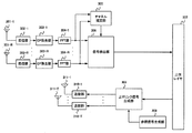
- FIG. 3 is a schematic block diagram showing the configuration of the terminal device in this embodiment.
- the terminal devices include reception antennas 301-1 to 301-R, reception units 302-1 to 302-R, CP removal units 303-1 to 303-R, FFT units 304-1 to 304-R, channel estimation unit 305, A signal detection unit 306, an upper layer 307, a reference signal generation unit 308, an uplink signal generation unit 309, transmission units 310-1 to 310-T, and transmission antennas 311-1 to 311-T are provided. Further, when a part or all of the terminal device is integrated into a chip to have an integrated circuit, it has a chip control circuit (not shown) for controlling each functional block. Note that the number of transmitting antennas T and the number of receiving antennas R are the same as those of the base station apparatus 100-2, but the number of antennas of the terminal apparatus and the base station apparatus may be the same or different.
- the terminal device receives signals with the receiving antennas 301-1 to 301-R, and performs frequency conversion, filtering, analog / digital conversion, etc. with the receiving units 302-1 to 302-R.
- the output of the receiving units 302-1 to 302-R is subjected to cyclic prefix removal by the CP removal units 303-1 to 303-R, and time frequency conversion is performed by the FFT units 304-1 to 304-R.
- Channel estimation section 305 obtains a channel estimation value using DMRS. If the DMRS is precoded, a channel estimate including precoding is obtained.
- the signal detection unit 306 removes the interference signal notified of the terminal information from the base station apparatus 100-2, suppresses other interference signals with linear weights, obtains information data transmitted to itself, and determines the upper layer 307. Output to.
- the terminal device also has a transmission function.
- the reference signal generation unit 308 generates an uplink reference signal.
- the uplink signal generation unit 309 includes information data obtained from higher layers, parameters for generating an uplink signal, reference signals obtained from the reference signal generation unit 308, information to be reported to the base station apparatus 100-2, etc. To generate an uplink signal.
- the uplink signal is a signal composed of an SC-FDMA (Single Carrier-Frequency Division Multiple Access) symbol or an OFDMA symbol.
- SC-FDMA Single Carrier-Frequency Division Multiple Access
- the output of the uplink signal generation unit 309 undergoes digital / analog conversion, filtering, frequency conversion, and the like in the transmission units 310-1 to 310-T, and is transmitted from the transmission antennas 311-1 to 311-T.
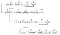
- FIG. 4 is a schematic block diagram showing the configuration of the signal detection unit 306.
- the signal detection unit 306 includes propagation path compensation units 401 and 406, a demodulation unit 402, a descrambling unit 403, a decoding unit 404, and an interference removal unit 405.
- the propagation path compensation unit 401 performs propagation path compensation using the reception weight, and suppresses inter-cell interference (and noise).
- Demodulation section 402 performs demodulation processing to determine a bit log likelihood ratio (LLR).
- LLR bit log likelihood ratio
- the demodulation unit 402 When demodulating a signal addressed to another terminal apparatus, the demodulation unit 402 performs demodulation using the terminal information.
- the descrambling unit 403 solves the scrambling performed in the base station apparatus and obtains the bit log likelihood ratio of the codeword.
- the decoding unit 404 performs error correction decoding on the bit log likelihood ratio of the codeword, and in the case of a signal transmitted to another terminal device, performs decoding using the terminal information, and obtains the encoded bit obtained
- the log likelihood ratio is output to the interference removal unit 405.
- information bits are obtained by decoding, and when decoding of all streams is not completed, the coded bit log likelihood ratio after decoding is output to the interference removal unit 405.
- the propagation path compensation unit 406 performs propagation path compensation on the signal after interference removal.
- the processing of the signal detection unit 306 will be described using mathematical expressions, taking the case of FIG. 1 as an example.
- the received signal r (k, t) in the resource element (k, t) of the terminal device 101 is shown in (1). Note that k and t are a subcarrier index and an OFDM symbol index, respectively.
- H 11 is a channel matrix between the base station apparatus 100-2 and the terminal apparatus 101
- s 1 is a signal transmitted from the base station apparatus 100-2 to the terminal apparatus 101
- H 12 is a base station apparatus 100- 2 is an interference channel matrix related to s 2 between the terminal apparatus 101 and s 2
- s 2 is a signal transmitted from the base station apparatus 100-2 to the terminal apparatus 102
- H 13 is the base station apparatus 100-1 and the terminal apparatus 101
- a channel matrix s 3 between the base station apparatus 100-1 and the base station apparatus 100-1 represents a signal transmitted to the terminal apparatus connected to the base station apparatus 100-1.
- N represents noise.
- the first term on the right side of Equation (1) represents the desired signal
- the second term represents inter-user interference (also referred to as a first interference signal)
- the third term represents inter-cell interference (also referred to as a second interference signal).
- a base station apparatus serving as an interference source for the first interference signal is referred to as a first base station apparatus
- a base station apparatus serving as an interference source for the second interference signal is referred to as a second base station apparatus.
- the second base station apparatus may be a single base station apparatus or a plurality of base station apparatuses.
- the propagation path compensation unit 401 performs propagation path compensation so as to suppress H 13 and n (that is, inter-cell interference and noise). For this, for example, a weight as shown in Equation (2) can be used.
- the channel compensation can be performed by multiplying the weight obtained by the equation (2) by the equation (1) from the left.
- H ⁇ represents a channel estimation value, and the one estimated by the channel estimation unit 305 is used.
- H represents a complex conjugate transpose matrix.
- R is an autocorrelation matrix of a received signal, and can be obtained using a resource element in which a reference signal (RS: Reference Signal) is arranged or a data channel (downlink shared channel: Physical Downlink Shared Channel).
- R In the case of obtaining using a reference signal, R can be obtained as in the following equation (3).
- Equation (4) is obtained using CRS (Cell Specific Reference Signal: Cell-Specific RS)
- Equation (5) is obtained using DM-RS. This is a case where Q is obtained.
- N CRS is the number of CRS resource elements used for calculating Q
- N DMRS is the number of DMRS resource elements used for calculating Q.
- following Formula (7) is a method of calculating
- DMRS is the sum of the number of data channels and DMRS resource elements used to calculate R.
- the interference between users is demodulated and decoded, and then the interference is removed.
- the interference streams are sequentially removed one by one will be described.
- interference removal is performed in order from the stream index 1, but the present invention is not limited to this, and an arbitrary interference removal order can be applied.
- the interference removal unit 405 When removing the first interference stream from the base station apparatus 100-2, the interference removal unit 405 performs interference removal as shown in Equation (8).
- Expression (8) is an expression representing processing in a certain resource element, but (k, t) is omitted except when necessary thereafter.
- ( ⁇ ) 1 represents the first column in the case of a matrix and the first element in the case of a vector.
- s ⁇ is a vector having as an element a symbol replica that is an expected value of a modulation symbol.
- the symbol replica can be obtained as shown in Equation (9) when QPSK modulation is taken as an example.
- ⁇ 1 and ⁇ 2 represent the log likelihood ratio of the first bit and the log likelihood ratio of the second bit, respectively, constituting the QPSK symbol.
- Tanh represents a hyperbolic tangent function
- j represents an imaginary unit.
- the propagation path compensation unit 406 performs propagation path compensation using the following weights.
- E [] represents an expected value.
- diag [] is a diagonal matrix having the parenthesized elements as diagonal elements.
- Q can be obtained using a reference signal in the same manner as in equations (4) and (5). Further, when obtaining using data, it can be obtained from the signal after interference removal as shown in the following equation (13).
- the second interference stream is decoded and, if necessary, the second interference stream is removed.
- Interference removal up to the xth (> 1) interference stream can be performed as in the following equation (14).
- the propagation path compensation unit 406 performs propagation path compensation using a weight such as the following equation (15).
- interference streams from the base station apparatus 100-2 can be removed. Even if the signal is destined for the terminal device itself, inter-stream interference occurs when the signals are spatially multiplexed, and thus the interference can be similarly removed by SIC.
- the interference removal up to the x-th (> 0) stream addressed to the own terminal apparatus can be performed by the following equation (19). However, S represents the number of interference streams from the base station apparatus 100-2.
- the propagation path compensation unit 406 can use a weight such as the following equation (20).
- the inter-user interference is detected and removed, and the inter-cell interference is subjected to interference suppression using the reception weight. Therefore, since only the interference in the same cell having a strong signal power is accurately removed, the throughput can be improved.
- interference streams are detected and removed one by one, but the present invention is not limited to this, and a plurality of interference streams can be detected and removed.
- detection and removal are performed from the interference stream.
- the present invention is not limited to this, and detection and removal may be performed from the desired stream. In this case, after removing the desired stream, the interference stream is detected and removed, and the desired stream is obtained again. Further, detection and removal of a desired stream and an interference stream may be repeated.
- the terminal device can set the interference stream to be detected and removed according to the number of repetitions.
- FIG. 5 is a schematic block diagram showing the configuration of the signal detection unit 306 in the present embodiment.
- the signal detection unit 306 includes a prefilter unit 501, a maximum likelihood detection unit 502, descrambling units 503-1 to 503-N, and decoding units 504-1 to 504-N.
- N represents the sum of the number of streams of the desired signal and the interference signal demodulated by the terminal device. That is, in the present embodiment, N is the sum of the number of streams from the base station device 100-2 and the number of streams from the base station device 100-1.
- the prefilter unit 501 multiplies the received signal by a weight that whitens inter-cell interference and noise.
- the maximum likelihood detection unit 502 performs maximum likelihood detection (MLD: Maximum Likelihood Detection) on the output of the prefilter unit 501, and obtains an encoded bit log likelihood ratio of the desired signal.
- the coded bit log likelihood ratio is descrambled by descrambling sections 503-1 to 503-N, and error correction decoded by decoding sections 504-1 to 504-N.
- the prefilter unit 501 multiplies the received signal r by a weight for whitening the interference noise as shown in Expression (24).
- the whitening weight can be obtained as, for example, the interference noise covariance matrix Q to Q ⁇ 1/2 .
- Q ⁇ 1/2 can be obtained by Cholesky decomposition or eigenvalue decomposition of the covariance matrix Q.
- Expression (25) is obtained by rewriting Expression (24) with r ′, H 11 ′, H 12 ′, H 13 ′, and n ′ being the received signal, channel matrix, and noise after multiplication by the whitening weight, respectively. is there.
- Equation (25) when the MMSE weight is obtained for Equation (25), it is the same as Equation (2). Since the whitening weight is multiplied, the covariance matrix of the interference noise is not obtained again and may be a unit matrix.
- the maximum likelihood detection unit 502 performs maximum likelihood detection on r ′ as shown in Expression (26).
- ⁇ q, n represents the log likelihood ratio of the nth bit of the modulation symbol of the qth stream in the desired signal.
- N1 is the number of streams of the desired signal
- M1 is the number of constellations of the modulated signal in the desired signal
- M1 4 for QPSK
- M1 16 for 16QAM
- M1 64 for 64QAM.
- N2 is the sum of the number of streams of the interference signal demodulated by the terminal device
- M2 is the sum of the number of constellations of the modulation signal in the interference signal.
- the maximum likelihood detection unit 502 does not have to calculate all transmission signal candidates, and can also obtain a bit log likelihood ratio from a part of the transmission signal candidates.
- a method of reducing transmission signal candidates for example, a method such as Sphere Decoding, M algorithm, QRM (QR decomposition and M algorithm) -MLD can be used.
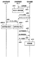
- FIG. 6 is a sequence diagram between the base station apparatus and the terminal apparatus according to the present embodiment.
- the terminal apparatus 101 detects a cell (cell ID) that can be used for communication using the synchronization signal, performs a cell search, and performs initial connection to the base station apparatus 100-2 (step s601).
- the base station device 100-2 grasps the neighboring cell (step s602).
- the base station apparatus 100-2 requests the terminal apparatus 101 to perform channel measurement of neighboring cells (step s603).
- the terminal apparatus 101 measures the channel of the neighboring cell instructed from the base station apparatus 100-2, and feeds back CSI to the base station apparatus 100-2 (step s604). At this time, the terminal apparatus 101 also feeds back the channel between the base station apparatus 100-2 and the terminal apparatus 101.
- Base station apparatuses 100-1 to 100-2 share a channel matrix between each base station apparatus and terminal apparatus 101 so that transmission / reception weights can be generated in each base station apparatus (step s605). For information sharing between base station apparatuses, an X2 interface can be used, and other methods can also be used.
- Base station apparatuses 100-1 to 100-2 calculate transmission / reception weights that suppress interference signals from base station apparatus 100-1 to terminal apparatus 101 (steps s606-1 and s606-2).
- the base station apparatus 100-2 notifies the terminal apparatus 101 of terminal information that causes interference with the terminal apparatus 101 (step s607).
- the base station apparatus 100-2 notifies the terminal apparatus 101 of necessary ones of the transmission weight of each base station apparatus and the reception weight of the terminal apparatus 101 (step s608).
- the notification of the weight may be changed depending on the version of the standard and the transmission mode. For example, when CRS is used for demodulation, the transmission weight is notified, but when RS and data are multiplied by the same precoding weight (for example, DMRS), the weight is not notified.
- the notification of the reception weight can be changed depending on whether the terminal device obtains the reception weight.
- the base station apparatus 100-2 transmits the precoded data to the terminal apparatus 101 (step s609).
- the terminal apparatus 101 suppresses the interference signal from the base station apparatus 100-1 by multiplying the reception weight, and detects and removes the interference signal from the base station apparatus 100-2 (step s610).
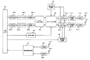
- FIG. 7 is a schematic block diagram showing the configuration of the base station apparatus 100-1 according to this embodiment.
- the base station apparatus 100-1 includes an upper layer 701, encoding units 702-1 to 702-S, scramble units 703-1 to 703-U, modulation units 704-1 to 704-U, a layer mapping unit 705, and weight generation.
- a chip control circuit that controls each functional block is provided.
- the upper layer 701 is a layer higher than the physical layer, for example, a MAC layer, a data link layer, a network layer, or the like.
- the upper layer 701 also notifies other parameters necessary for each part of the base station device 100-2 to function.
- the encoding units 702-1 to 702-U perform error correction encoding on the information data input from the upper layer 701 to generate encoded bits (codewords). Encoding sections 702-1 to 702-U rate the encoded bit sequence in order to match the coding rate of the error correction-encoded data sequence with the encoding rate corresponding to the data transmission rate. A matching process may be performed.
- the encoding units 702-1 to 702-U may have a function of rearranging and interleaving the error correction encoded data series.
- the scramblers 703-1 to 703-U scramble the code words input from the encoders 702-1 to 702-U based on the cell IDs.
- the scrambled codeword is mapped to modulation symbols by modulation sections 704-1 to 704-U.
- Modulation sections 704-1 to 704-U may have a function of rearranging modulation symbols and interleaving.
- the modulation symbol is layer-mapped by the layer mapping unit 705 for spatial multiplexing.
- the weight generation unit 706 generates transmission / reception weights for interference suppression using channel information from neighboring cells.
- the reference signal generation unit 707 generates a reference signal, and outputs a reference signal that requires precoding to the precoding 708 and a reference signal that is not precoded to the resource mapping units 710-1 to 710-T.
- the precoding unit 708 performs precoding on the output of the layer mapping unit 705 and the input reference signal using the transmission weight generated by the weight generation unit 706.
- the terminal information generation unit 709 generates information on other terminal devices for the terminal device 101 to detect and remove interference signals.
- Resource mapping units 710-1 to 710-T map information indicating the output of precoding unit 708, reference signals, and terminal information to resources.
- information indicating the transmission / reception weight is mapped to the resource.
- Outputs of the resource mapping units 710-1 to 710-T are IFFT and cyclic prefix insertion performed by the OFDM signal generation units 711-1 to 711-T, and digital signals are transmitted from the transmission units 712-1 to 712-T. Analog conversion, filtering, frequency conversion, and the like are performed and transmitted from the transmission antennas 713-1 to 713-T.
- the base station apparatus 100-2 also has a receiving function.
- the receiving antennas 714-1 to 714-R receive signals from the terminal device 101, and the receiving units 715-1 to 715-R perform frequency conversion, filtering, analog / digital conversion, and the like.
- the report information detection unit 716 obtains information necessary for scheduling and a channel matrix between the base station device 100-2 and the terminal device 101 based on the CSI fed back from the terminal device 101.
- Equation (27) is a received signal in the resource element (k, t) as in Equation (1), but (k, t) is omitted unless necessary.
- V 1 is a transmission weight in base station apparatus 100-2
- V 2 is a transmission weight in base station apparatus 100-1
- H 11 represents a channel matrix between the base station apparatus 100-2 and the terminal apparatus 101 in this embodiment. H 11 includes a desired signal channel and an inter-user interference channel.
- s is a transmission signal from the base station apparatus 100-2 to the terminal apparatuses 101 and 102.
- H 12 represents a channel matrix between the base station apparatus 100-1 and the terminal apparatus 101.
- s 2 is a transmission signal from the base station apparatus 100-1 to the terminal apparatus connected to the base station apparatus 100-1.
- Each transmission weight and reception weight may be different for each subcarrier, or may be the same for a plurality of subcarriers such as resource blocks.
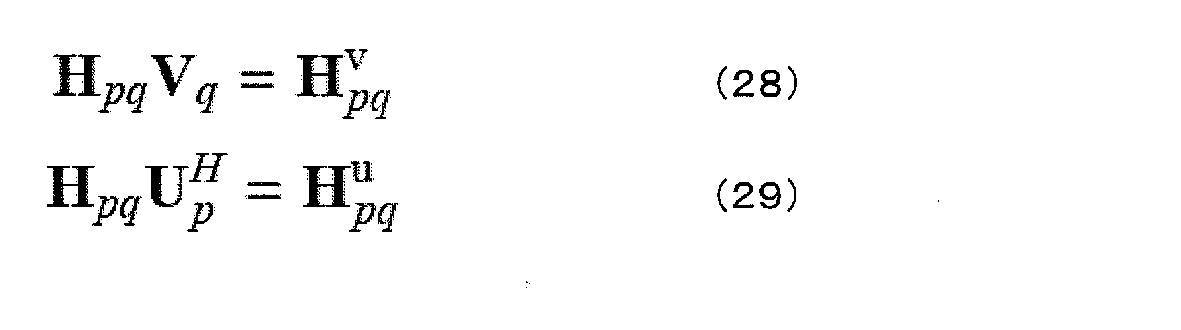
- An equivalent channel obtained by combining the channel matrix and the transmission weight is represented by Expression (28), and an equivalent channel obtained by combining the channel matrix and the reception weight is represented by Expression (29). Note that Up is a reception weight.
- the transmission weight in each base station apparatus can be obtained as an eigenvector of several eigenvalues of signals detected by the terminal apparatus connected from the larger one of the equations (30) and (31). That is, the eigenvector of equation (30) is V 1 , and the eigenvector of equation (31) is V 2 .
- V 1 and V 2 obtained here are obtained so as to maximize SLNR (Signal to Leakage and Noise power Ratio), but the present invention is not limited to this. Alternatively, it may be obtained by a ZF (Zero Forcing) standard or an MMSE (Minimum Mean Square Error) standard.
- the transmission weight is obtained assuming the reception weight, but the transmission weight may be obtained without assuming the reception weight. When no reception weight is assumed, the reception weight may be a unit matrix.
- the reception weight in each terminal device can be obtained as an eigenvector of eigenvalues of several streams from the larger one in each equation (32) and (33).
- the reception weight in the terminal device 101 can be obtained from Equation (32).
- Expression (33) it is possible to obtain a reception weight in a terminal device (not shown) connected to the base station device 100-1.
- the base station apparatus can also obtain transmission weights assuming reception weights. At this time, the base station apparatus can also obtain reception weights assuming transmission weights. Further, by repeatedly obtaining the transmission weight and the reception weight repeatedly, the interference suppression performance can be improved. Note that the initial values of the transmission weight and the reception weight may be arbitrarily set, and the weights when the mutual weights are not taken into consideration can be used. The transmission weight and the reception weight can be obtained using a channel covariance matrix.
- each base station apparatus obtains all transmission weights and reception weights.
- the present invention is not limited to this, and one base station apparatus obtains all transmission weights and reception weights. It is also possible to notify each base station apparatus of the necessary weight. Further, the base station apparatus may notify the terminal apparatus of the calculated reception weight, or the base station apparatus may determine the terminal apparatus without notifying the terminal apparatus.
- the transmission / reception weight suppresses the interference signal from the base station apparatus 100-2.
- the interference signal from the base station apparatus 100-1 can be removed by interference as in the first embodiment, or maximum likelihood detection can be performed as in the second embodiment.
- the terminal apparatus detects and removes the stream in the same cell from the interference streams, and suppresses the inter-cell interference stream using the transmission weight or the transmission weight and the reception weight. Explained how to do. Therefore, even when all the interference streams cannot be detected, the interference can be suppressed and the throughput can be improved.
- the present invention is not limited to this, and interference signals arrive from a plurality of base station apparatuses. Even in this case, the present invention can be applied.
- interference signals from one base station apparatus are suppressed using weights.
- the present invention is not limited to this, and interference signals from a plurality of base station apparatuses are suppressed.
- the present invention can be applied even in the case of suppression.
- the terminal device can detect and remove interference caused by signals addressed to two or more terminal devices in the cell. Note that the terminal device does not have to detect and remove all the interference streams in the cell, and only needs to detect and remove a part of the interference streams.
- the program that operates in the base station apparatus and mobile station apparatus is a program (a program that causes a computer to function) that controls the CPU and the like so as to realize the functions of the above-described embodiments according to the present invention.
- Information handled by these devices is temporarily stored in the RAM at the time of processing, then stored in various ROMs and HDDs, read out by the CPU as necessary, and corrected and written.
- a recording medium for storing the program a semiconductor medium (for example, ROM, nonvolatile memory card, etc.), an optical recording medium (for example, DVD, MO, MD, CD, BD, etc.), a magnetic recording medium (for example, magnetic tape, Any of a flexible disk etc. may be sufficient.
- the processing is performed in cooperation with the operating system or other application programs.
- the functions of the invention may be realized.
- the program when distributing to the market, can be stored and distributed on a portable recording medium, or transferred to a server computer connected via a network such as the Internet.
- the storage device of the server computer is also included in the present invention.
- part or all of the mobile station apparatus and the base station apparatus in the above-described embodiment may be realized as an LSI that is typically an integrated circuit.
- Each functional block of the receiving apparatus may be individually chipped, or a part or all of them may be integrated into a chip. When each functional block is integrated, an integrated circuit controller for controlling them is added.
- the method of circuit integration is not limited to LSI, and may be realized by a dedicated circuit or a general-purpose processor.
- an integrated circuit based on the technology can also be used.
- the terminal device of the present invention is not limited to application to a mobile station device, but is a stationary or non-movable electronic device installed indoors or outdoors, such as AV equipment, kitchen equipment, cleaning / washing equipment Needless to say, it can be applied to air conditioning equipment, office equipment, vending machines, and other daily life equipment.
- the present invention is suitable for use in a terminal device and a receiving method.
Landscapes
- Engineering & Computer Science (AREA)
- Computer Networks & Wireless Communication (AREA)
- Signal Processing (AREA)
- Mobile Radio Communication Systems (AREA)
Abstract
多くの干渉ストリームを受信する場合であっても、セル間干渉、ユーザ間干渉による受信性能の劣化を軽減すること。第1の基地局装置と接続している端末装置であって、第1の基地局装置からのユーザ間干渉である第1の干渉信号と、第2の基地局装置からのセル間干渉である第2の干渉信号とを受信し、前記第1の干渉信号のうち少なくとも1つの干渉ストリームは前記第1の基地局装置から通知される端末情報を用いて復調し、前記第2の干渉信号は受信重みを用いて抑圧すること。
Description
本発明は、端末装置及び受信方法に関する。
近年、スマートフォンやタブレット端末の普及に伴い、モバイル伝送におけるトラフィックは、指数的に増大を続けており、今後もさらに増大することが予想されている。このような無線トラフィック増大の対策の1つとして、ヘテロジーニアスネットワーク(Heterogeneous Network)による基地局の高密度配置の検討が行われている。基地局の高密度配置は、マクロセル内に小電力基地局(LPN:Low Power Node)等を配置し、端末装置が小電力基地局に接続することで、マクロ基地局の負荷を軽減するものである。この時、セル間干渉(Inter-Cell Interference)が問題となる。
また、セルスループットを向上させるために、複数の端末装置を空間多重するMU-MIMO(Multi-User Multiple Input Multiple Output)の検討も行われている。MU-MIMOでは、端末装置間の干渉(ユーザ間干渉)が問題となる。
このようなセル間干渉やユーザ間干渉に対して、3GPP(3rd Generation Partnership Project)では、端末装置が干渉信号を抑圧または除去するNAICS(Network Assisted Interference Cancellation and Suppression)の検討が行われている。NAICSでは、端末装置は、干渉となっている他の端末装置に関する情報を受け取り、干渉となっている他の端末装置宛の信号を検出し、干渉除去を行う。NAICSについては、非特許文献1に記載されている。
RP-130404、"Study on Network-Assisted Interference Cancellation and Suppression for LTE、" 3GPP TSG RAN Meeting #59、2013年 3月。
しかしながら、NAICSでは、干渉信号を検出して除去を行うため、精度良く干渉信号を検出するためには、端末装置が備える受信アンテナ数を干渉信号ストリーム数よりも多くする必要がある。従って、受信アンテナ数よりも多くの干渉ストリームを受信する場合や多数の受信アンテナを搭載できない小型端末装置では、高精度に干渉除去が行えず、受信性能が劣化するという問題がある。
本発明はこのような事情を鑑みてなされたものであり、その目的は、多くの干渉ストリームを受信する場合であっても、セル間干渉、ユーザ間干渉による受信性能の劣化を軽減することが可能な端末装置及び受信方法を提供することにある。
上述した課題を解決するために本発明に係る端末装置及び受信方法の構成は、次の通りである。
本発明の端末装置は、第1の基地局装置と接続している端末装置であって、
第1の基地局装置からのユーザ間干渉である第1の干渉信号と、第2の基地局装置からのセル間干渉である第2の干渉信号とを受信し、
前記第1の干渉信号のうち少なくとも1つの干渉ストリームは前記第1の基地局装置から通知される端末情報を用いて復調し、前記第2の干渉信号は受信重みを用いて抑圧することを特徴とする。
第1の基地局装置からのユーザ間干渉である第1の干渉信号と、第2の基地局装置からのセル間干渉である第2の干渉信号とを受信し、
前記第1の干渉信号のうち少なくとも1つの干渉ストリームは前記第1の基地局装置から通知される端末情報を用いて復調し、前記第2の干渉信号は受信重みを用いて抑圧することを特徴とする。
また、本発明の端末装置において、前記第2の基地局装置は複数であることを特徴とする。
また、本発明の端末装置において、前記第2の干渉信号を抑圧した後に前記第1の干渉信号を抑圧することを特徴とする。
また、本発明の基地局装置は、複数の基地局装置と協調している基地局装置であって、該基地局装置が接続している端末装置に対して、ユーザ間干渉である第1の干渉信号を復調するための端末情報を通知し、セル間干渉は他の基地局装置と協調して抑圧することを特徴とする。
また、本発明の受信方法は、第1の基地局装置と接続している端末装置における受信方法であって、第1の基地局装置からのユーザ間干渉である第1の干渉信号と、第2の基地局装置からのセル間干渉である第2の干渉信号とを受信し、前記第1の干渉信号のうち少なくとも1つの干渉ストリームは前記第1の基地局装置から通知される端末情報を用いて復調し、前記第2の干渉信号は受信重みを用いて抑圧することを特徴とする。
本発明によれば、第1の干渉信号と第2の干渉信号を受信し、前記第1の干渉信号は、前記基地局装置から通知される端末情報を用いて復調し、前記第2の干渉信号は受信重みを用いて抑圧するようにした。従って、多くの干渉ストリームを受信する場合であっても、セル間干渉、ユーザ間干渉による受信性能の劣化を軽減できるため、スループットを向上させることができる。
(第1の実施形態)
以下、本発明の第1の実施形態について説明する。本実施形態における通信システムは、基地局(送信装置、セル、送信点、送信アンテナ群、送信アンテナポート群、コンポーネントキャリア、eNodeB)および端末(端末装置、移動端末、受信点、受信端末、受信装置、受信アンテナ群、受信アンテナポート群、UE)を備える。
以下、本発明の第1の実施形態について説明する。本実施形態における通信システムは、基地局(送信装置、セル、送信点、送信アンテナ群、送信アンテナポート群、コンポーネントキャリア、eNodeB)および端末(端末装置、移動端末、受信点、受信端末、受信装置、受信アンテナ群、受信アンテナポート群、UE)を備える。
図1は、第1の実施形態に係る通信システムの一例を示す図である。図1には、基地局装置(マクロ基地局、第1の基地局ともいう)100-1、マクロ基地局よりも送信電力が低い基地局装置(LPN:Low Power Node、小電力基地局、第2の基地局ともいう)100-2、端末装置101、102を備える。100-1aは、マクロ基地局100-1のカバレッジ(マクロセル)、100-2aは小電力基地局100-2のカバレッジ(ピコセル、スモールセル等)である。カバレッジとは、基地局装置が端末装置と接続可能な範囲(通信エリア)をいう。なお、以下では、マクロ基地局と小電力基地局でマルチセルを構成している例を説明するが、本発明はこれに限らず、マクロ基地局のみでマルチセルを構成しても良いし、小電力基地局のみでマルチセルを構成しても良い。また、マクロ基地局と端末装置が接続している場合を図示していないが、マクロ基地局と端末装置が接続する場合も本発明に含まれる。また、基地局装置間は、無線接続されていても良いし、有線接続されていても良い。
また、小電力基地局が複数ある場合、小電力基地局毎に送信電力が異なっていても良い。また、マクロ基地局と小電力基地局は、送信電力の区別のみならず、既にサービスインしている方式をサポートする後方互換性のある基地局と、新しく定義される後方互換性のない基地局とで区別しても良い。
また、小電力基地局間でサービスする方式(通信システムのバージョン、オプション等)が異なっていても良い。
また、本発明は、セル数、基地局の数、端末装置の数、セルの種類(例えば、マクロセル、ピコセル、フェムトセル、スモールセル等)、基地局の種類は以下の実施形態に限定されない。また、図1では、スモールセルがマクロセルと完全に重なっているが、部分的に重なっていても良いし、重なっていなくても良い。
図2は、本実施形態における基地局装置100-2の構成を示す概略ブロック図である。基地局装置100-2は、上位レイヤ201、符号化部202-1~202-U、スクランブル部203-1~203-U、変調部204-1~204-U、レイヤマッピング部205、参照信号生成部206、プレコーディング部207、端末情報生成部208、リソースマッピング209-1~209-T、OFDM信号生成部210-1~210-T、送信部211-1~211-T、送信アンテナ212-1~212-T、受信アンテナ213-1~213-R、受信部214-1~214-R、報告情報検出部215を備える。なお、図中のUは、空間多重するストリーム数を表し、少なくとも1つのストリームは異なる端末装置宛である。また、T、Rはそれぞれ、送信アンテナ数、受信アンテナ数を表す。なお、上記基地局装置100-2の一部あるいは全部をチップ化して集積回路となる場合、各機能ブロックに対して制御を行うチップ制御回路を有する。
上位レイヤ201は、OSI参照モデルで定義された通信機能の階層のうち、物理層(Physical Layer)よりも上位の機能の階層、例えばMAC(媒体アクセス制御:Media Access Control)層、データリンク層、ネットワーク層等である。また、上位レイヤ201は、基地局装置100-2を構成する各部位が、機能を発揮するために必要なその他のパラメータも通知する。
符号化部202-1~202-Uは、上位レイヤ201から入力された情報データに対して、誤り訂正符号化を行い、符号化ビット(コードワードともいう)を生成する。また、情報データは、例えば、通話に伴う音声信号、撮影した画像を表す静止画像又は動画像信号、文字メッセージ等である。符号化部202-1~202-Uが誤り訂正符号化を行う際に用いる符号化方式は、例えば、ターボ符号化(Turbo Coding)、畳み込み符号化(Convolutional Coding)、低密度パリティ検査符号化(Low Density Parity Check coding;LDPC)等である。
なお、符号化部202-1~202-Uは、誤り訂正符号化したデータ系列の符号化率(coding rate)をデータ伝送率に対応する符号化率に合わせるために、符号化ビット系列に対してレートマッチング処理を行っても良い。また、符号化部202-1~202-Uは、誤り訂正符号化したデータ系列を並び替えてインターリーブする機能を有しても良い。
スクランブル部203-1~203-Uは、符号化部202-1~202-Uから入力されるコードワードに対して、それぞれセルIDに基づいたスクランブルを行う。
スクランブルされたコードワードは、変調部204-1~204-Uにおいて、変調シンボルにマッピングされる。変調部204-1~204-Uが行う変調処理は、例えば、BPSK(Binary Phase Shift Keying;2相位相変調)、QPSK(Quadrature Phase Shift Keying;4相位相変調)、M-QAM(M-Quadrature Amplitude Modulation;M値直交振幅変調、例えば、M=16、64、256、1024、4096)などである。なお、変調部204-1~204-Uは、生成した変調シンボルを並び替えてインターリーブする機能を有しても良い。
変調シンボルは、レイヤマッピング部205において、空間多重のためにレイヤマッピングされる。例えば、LTE-A(LTE-Advanced)では最大で8レイヤまでサポートされており、1つのコードワードは最大で4レイヤにマッピングされる。
参照信号生成部206は、参照信号を生成して、プレコーディングが必要な参照信号をプレコーディング部207に、プレコーディングしない参照信号をリソースマッピング部209-1~209-Tに出力する。
プレコーディング部207は、レイヤマッピング部205の出力に対してプレコーディングを行う。なお、一部の参照信号、例えばDMRS(復調用参照信号:DeModulation Reference Symbol)は、復調するデータ信号と同じプレコーディングされても良い。
端末情報生成部208は、空間多重されている各端末装置が干渉信号の検出及び除去を行うための他端末装置の情報(端末情報ともよぶ)を生成する。例えば、端末装置101と端末装置102が空間多重されている場合、端末装置101には端末装置102の端末情報を通知し、端末装置102には端末装置101の端末情報を通知する。端末情報は、例えば、セルID、変調方式、符号化率、参照信号、アンテナポート番号、リソース割り当て情報など、他端末装置宛の信号を復調、復号するために必要な情報である。端末情報は、制御信号とすることができる。
リソースマッピング部209-1~209-Tはプレコーディング部207の出力、参照信号、端末情報をリソースにマッピングする。
リソースマッピング部209-1~209-Tの出力は、OFDM(直交周波数分割多重:Orthogonal Frequency Division Multiplexing)信号生成部210-1~210-Tで、IFFT(逆高速フーリエ変換:Inverse Fast Fourier Transform)、サイクリックプレフィックス(CP:Cyclic Prefix)の挿入が行われ、送信部211-1~211-Tでデジタル・アナログ変換、フィルタリング、周波数変換等が行われ、送信アンテナ212-1~212-Tから送信される。
基地局装置100-2は、受信する機能も備える。受信アンテナ213-1~213-Rは、端末装置からの信号を受信し、受信部213-1~213-Rで、周波数変換、フィルタリング、アナログ・デジタル変換等を行う。報告情報検出部215は、端末装置からフィードバックされたCSI(Channel State Information)などランク数、MCS(変調符号化方式:Modulation and Coding Scheme)の決定に必要な情報や、干渉信号のチャネル情報などを求める。チャネル情報には、チャネル行列、チャネル共分散行列や、チャネル行列やチャネル共分散行列を示す情報など、プレコーディングに必要な情報が含まれる。
図3は、本実施形態における端末装置の構成を示す概略ブロック図である。端末装置は、受信アンテナ301-1~301-R、受信部302-1~302-R、CP除去部303-1~303-R、FFT部304-1~304-R、チャネル推定部305、信号検出部306、上位レイヤ307、参照信号生成部308、上りリンク信号生成部309、送信部310-1~310-T、送信アンテナ311-1~311-Tを備える。また、端末装置の一部あるいは全部をチップ化して集積回路となる場合、各機能ブロックに対して制御を行うチップ制御回路(図示せず)を有する。なお、送信アンテナ本数T、受信アンテナ本数Rは、基地局装置100-2と同じ表記をしているが、端末装置と基地局装置のアンテナ本数は同じであっても異なっても良い。
端末装置は、受信アンテナ301-1~301-Rで信号を受信し、受信部302-1~302-Rで周波数変換、フィルタリング、アナログ・デジタル変換等を行う。受信部302-1~302-Rの出力は、CP除去部303-1~303-Rでサイクリックプレフィックスの除去が行われ、FFT部304-1~304-Rで時間周波数変換が行われる。チャネル推定部305は、DMRSを用いてチャネル推定値を求める。DMRSがプレコーディングされている場合は、プレコーディングを含んだチャネル推定値が求まる。信号検出部306は、基地局装置100-2から端末情報を通知された干渉信号を除去し、他の干渉信号は線形重みで抑圧し、自己宛に送信された情報データを求め、上位レイヤ307に出力する。
端末装置は、送信する機能も備える。参照信号生成部308は、上りリンク用の参照信号を生成する。上りリンク信号生成部309は、上位レイヤから得られる情報データや上りリンク信号を生成するためのパラメータ等や、参照信号生成部308から得られる参照信号、基地局装置100-2に報告する情報等から上りリンク信号を生成する。上りリンク信号はSC-FDMA(Single Carrier-Frequency Division Multiple Access)シンボルやOFDMAシンボルで構成された信号である。上りリンク信号生成部309の出力は、送信部310-1~310-Tでデジタル・アナログ変換、フィルタリング、周波数変換等が行われ、送信アンテナ311-1~311-Tから送信される。
図4は信号検出部306の構成を示す概略ブロック図である。信号検出部306は、伝搬路補償部401、406、復調部402、デスクランブル部403、復号部404、干渉除去部405を備える。伝搬路補償部401は、受信重みを用いて伝搬路補償を行い、セル間干渉(及び雑音)を抑圧する。復調部402は、復調処理を行ってビット対数尤度比(LLR:Log Likelihood Ratio)を求める。他端末装置宛の信号を復調する場合、復調部402は、端末情報を用いて復調を行う。デスクランブル部403は、基地局装置で行われたスクランブルを解き、コードワードのビット対数尤度比を求める。復号部404は、コードワードのビット対数尤度比に対して誤り訂正復号を行い、他端末装置宛に送信された信号の場合は、端末情報を用いて復号を行い、得られた符号化ビット対数尤度比を干渉除去部405に出力する。自端末装置宛の信号であった場合、復号により情報ビットを求めると共に、全てのストリームの復号が終わっていない場合、復号後の符号化ビット対数尤度比を干渉除去部405に出力する。伝搬路補償部406は、干渉除去後の信号に対して伝搬路補償を行う。
信号検出部306の処理を、図1の場合を例に数式を用いて説明する。端末装置101のリソースエレメント(k、t)における受信信号r(k、t)を(1)に示す。なお、k、tはそれぞれサブキャリアインデックス、OFDMシンボルインデックスである。

なお、H11は基地局装置100-2と端末装置101との間のチャネル行列、s1は基地局装置100-2から端末装置101宛に送信された信号、H12は基地局装置100-2と端末装置101との間のs2に関する干渉チャネル行列、s2は基地局装置100-2から端末装置102宛に送信された信号、H13は基地局装置100-1と端末装置101との間のチャネル行列、s3は基地局装置100-1から基地局装置100-1と接続している端末装置宛に送信された信号を表す。また、nは雑音を表す。つまり、式(1)の右辺第1項は所望信号、第2項はユーザ間干渉(第1の干渉信号ともよぶ)、第3項はセル間干渉(第2の干渉信号ともよぶ)を表す。なお、第1の干渉信号の干渉源となる基地局装置を第1の基地局装置、第2の干渉信号の干渉源となる基地局装置を第2の基地局装置とよぶ。なお、第2の基地局装置は1つの基地局装置であっても複数の基地局装置であっても良い。
伝搬路補償部401は、H13及びn(つまり、セル間干渉及び雑音)を抑圧するように伝搬路補償を行う。これは、例えば、式(2)のような重みを用いることができる。式(2)で求めた重みを式(1)に左から乗算して伝搬路補償を行うことができる。

ただし、H^はチャネル推定値を表し、チャネル推定部305で推定したものを用いる。また、上付きのHは複素共役転置行列を表す。なお、Rは受信信号の自己相関行列であり、参照信号(RS:Reference Signal)が配置されるリソースエレメントやデータチャネル(下りリンク共有チャネル:Physical Downlink Shared Channel)を用いて求めることができる。
参照信号を用いて求める場合、Rは次式(3)のように求めることができる。

ただし、Qは干渉雑音の共分散行列であり、式(4)はCRS(セル固有参照信号:Cell-Specific RS)を用いてQを求めた場合、式(5)はDM-RSを用いてQを求めた場合である。

NCRSはQの算出に用いたCRSリソースエレメント数であり、NDMRSはQの算出に用いたDMRSリソースエレメント数である。
また、次式(7)はデータチャネルやDMRSリソースエレメントを用いてRを求める方法である。

NPDSCH,DMRSは、Rの算出に用いたデータチャネル、DMRSリソースエレメント数の和である。
伝搬路補償後、全ストリームを復調、復号することもできるが、以下では、逐次型干渉キャンセラ(SIC:Successive Interference Canceller)を適用した場合を説明する。
式(2)を用いた伝搬路補償後、ユーザ間干渉について復調、復号した後、干渉除去を行う。干渉ストリーム全てを一括して除去することも可能であるが、ここでは干渉ストリームを1つずつ逐次的に除去する場合を説明する。なお、以降の説明では、ストリームインデックス1から順番に干渉除去を行っていくが、本発明はこれに限らず、任意の干渉除去順を適用することができる。
基地局装置100-2からの第1干渉ストリームを除去する場合、干渉除去部405は式(8)のように干渉除去を行う。なお、式(8)はあるリソースエレメントにおける処理を表す数式であるが、以降では必要なとき以外は(k、t)を省略する。
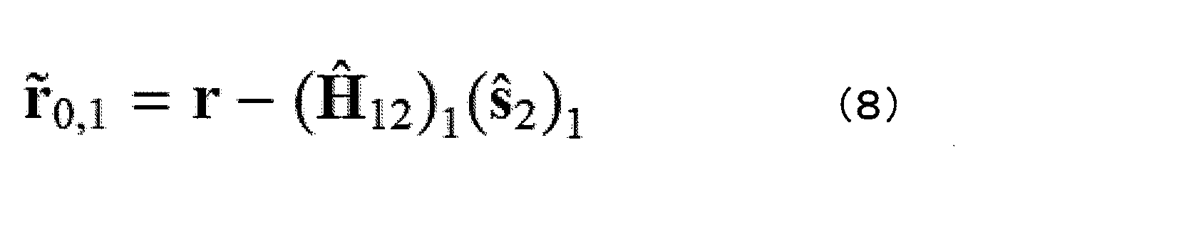
なお、(・)1は、行列の場合は第1列、ベクトルの場合は第1要素を表す。また、s^は変調シンボルの期待値であるシンボルレプリカを要素に持つベクトルである。シンボルレプリカは、QPSK変調を例にすると、式(9)のように求めることができる。

ただし、λ1、λ2はそれぞれQPSKシンボルを構成する第1ビットの対数尤度比、第2ビットの対数尤度比を表す。また、tanhは双曲線正接関数を表し、jは虚数単位を表す。
このとき、伝搬路補償部406は次のような重みを用いて伝搬路補償を行う。
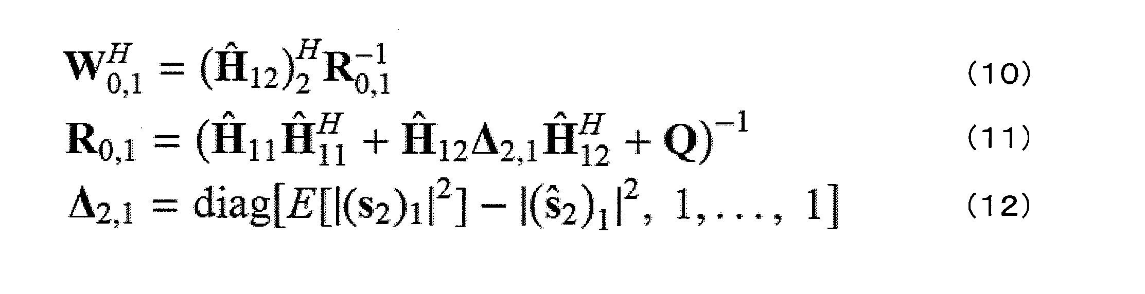
ただし、E[]は期待値を表す。また、diag[]は括弧内を対角要素に持つ対角行列である。Qは式(4)、(5)と同様に参照信号を用いて求めることができる。また、データを用いて求める場合は次式(13)のように干渉除去後の信号から求めることができる。

伝搬路補償後、第2干渉ストリームの復号を行い、必要な場合は、第2干渉ストリームの除去を行う。第x(>1)干渉ストリームまでの干渉除去は次式(14)のように行うことができる。

このとき、伝搬路補償部406は、次式(15)のような重みを用いて伝搬路補償する。

なお、データを用いてR0,xを求める場合は、次式(18)のようにすることができる。

以降、基地局装置100-2からの干渉ストリームを全て除去することができる。また、自端末装置宛の信号であっても、空間多重されている場合はストリーム間干渉が生じているため、同様にSICにより干渉を除去できる。自端末装置宛の第x(>0)ストリームまでの干渉除去は次式(19)のようにすることができる。ただし、Sは基地局装置100-2からの干渉ストリーム数を表す。

このとき、伝搬路補償部406では次式(20)のような重みを用いることができる。

また、データを用いる場合、Rx,Sは次式(23)のように求めることができる。

このように、自端末装置宛の信号が全て復号されるまで行う。
このように、本実施形態では、ユーザ間干渉は検出及び除去を行い、セル間干渉は受信重みを用いて干渉抑圧を行った。従って、信号電力の強い同一セル内の干渉のみを精度良く除去しているため、スループットを向上させることができる。
上述のように、本実施形態では、干渉ストリームを1つずつ検出及び除去を行っていたが、本発明はこれに限らず、複数の干渉ストリームを検出及び除去を行うことも可能である。また、本実施形態では、干渉ストリームから検出及び除去を行っていたが、本発明はこれに限らず、所望ストリームから検出及び除去しても良い。この場合、所望ストリームを除去した後、干渉ストリームの検出及び除去を行い、再度所望ストリームを求めれば良い。また、所望ストリーム、干渉ストリームの検出及び除去を繰り返し行っても良い。なお、所望ストリーム、干渉ストリームの検出及び除去を繰り返し行う場合、繰り返し回数によって、検出及び除去を行う干渉ストリームを端末装置が設定することも可能である。例えば、1つ前までの繰り返しで、ユーザ間干渉のうち一部の信号が精度良く検出できている場合、再度検出する必要はない。このようにすると、全ての繰り返しでユーザ間干渉の全てを検出及び除去を行う場合と比べて、演算量を削減することができる。
(第2の実施形態)
本実施形態と第1の実施形態は、信号検出部306のみが異なるため、信号検出部306のみ説明する。
本実施形態と第1の実施形態は、信号検出部306のみが異なるため、信号検出部306のみ説明する。
図5は本実施形態における信号検出部306の構成を示す概略ブロック図である。信号検出部306は、プレフィルタ部501、最尤検出部502、デスクランブル部503-1~503-N、復号部504-1~504-Nを備える。なお、Nは所望信号と端末装置が復調する干渉信号のストリーム数の和を表す。つまり本実施形態では、Nは、基地局装置100-2からのストリーム数と基地局装置100-1からのストリーム数の和となる。
プレフィルタ部501は、セル間干渉及び雑音を白色化する重みを受信信号に乗算する。最尤検出部502は、プレフィルタ部501の出力に対し、最尤検出(MLD:Maximum Likelihood Detection)を行い、所望信号の符号化ビット対数尤度比を求める。符号化ビット対数尤度比は、デスクランブル部503-1~503-Nでデスクランブルされ、復号部504-1~504-Nで誤り訂正復号される。
本実施形態における信号検出部306の処理を、数式を用いて説明する。プレフィルタ部501は、受信信号rに対して、式(24)に示すように、干渉雑音を白色化する重みを乗算する。この白色化重みは、例えば、干渉雑音の共分散行列QからQ-1/2として求めることができる。Q-1/2は、共分散行列Qのコレスキ-分解や固有値分解によって求めることができる。

式(25)は、白色化重み乗算後の受信信号、チャネル行列、雑音をそれぞれr’、H11’、H12’、H13’、n’として、式(24)を書きなおしたものである。

なお、式(25)に対してMMSE重みを求めると、式(2)と同様になる。なお、白色化重みを乗算しているので、干渉雑音の共分散行列は改めて求めず、単位行列として良い。最尤検出部502はr’に対して式(26)のように最尤検出を行う。

λq,nは、所望信号における第qストリームの変調シンボルの第nビットの対数尤度比を表す。s1,bはビット列b=[b1,1,…,bN1,M1]で定めるs1の送信信号候補を表す。なお、N1は所望信号のストリーム数、M1は所望信号における変調信号のコンスタレーション数であり、QPSKではM1=4、16QAMではM1=16、64QAMではM1=64である。また、s2,cはビット列c=[c1,1,…cN2,M2]で定めるs2の送信信号候補を表す。なお、N2は端末装置で復調する干渉信号のストリーム数の和、M2は干渉信号における変調信号のコンスタレーション数の和である。また、b+はbのうちbq,n=1となる集合を表しており、b+=[b1,1,…,bq,n=1,…,bN1,M1]である。b-はbのうちbq,n=0となる集合を表しており、b-=[b1,1,…,bq,n=0,…,bN1,M1]である。従って、λq,nはb+を用いて生成される最小メトリックとb-を用いて生成される最小メトリックの差で求められる。
なお、最尤検出部502は、全ての送信信号候補を計算しなくても良く、送信信号候補の一部からビット対数尤度比を求めることもできる。送信信号候補を削減する方法としては、例えば、Sphere Decoding、Mアルゴリズム、QRM(QR decomposition and M algorithm)-MLDなどの方法を用いることができる。
このように上記第2の実施形態では、端末装置が受信するセル間干渉及び雑音を白色化するプレフィルタを乗算後、最尤検出を行った。従って、セル間干渉を抑圧しつつ、同一セル内干渉ストリームに関しては最尤検出を行うことができるようになった。
(第3の実施形態)
図6は、本実施形態に係る基地局装置と端末装置との間のシーケンス図である。一例として、図1の端末装置101が基地局装置100-2に接続する場合を説明する。端末装置101は、同期信号を用いて通信に利用可能なセル(セルID)を検出してセルサーチを行い、基地局装置100-2に初期接続を行う(ステップs601)。基地局装置100-2は周辺セルを把握する(ステップs602)。基地局装置100-2は、端末装置101に対して周辺セルのチャネル測定を要求する(ステップs603)。端末装置101は、基地局装置100-2から指示された周辺セルのチャネルを測定し、基地局装置100-2にCSIをフィードバックする(ステップs604)。このとき、端末装置101は、基地局装置100-2と端末装置101との間のチャネルもフィードバックする。基地局装置100-1~100-2は、各基地局装置で送受信重みが生成できるように、各基地局装置と端末装置101との間のチャネル行列を共有する(ステップs605)。基地局装置間の情報共有は、X2インターフェースを用いることもできるし、その他の方法を用いることもできる。基地局装置100-1~100-2は、基地局装置100-1から端末装置101への干渉信号が抑圧されるような送受信重みを算出する(ステップs606-1、s606-2)。基地局装置100-2は端末装置101と干渉となる端末情報を端末装置101に通知する(ステップs607)。基地局装置100-2は、各基地局装置の送信重み、端末装置101における受信重みのうち必要なものを端末装置101に通知する(ステップs608)。重みの通知は、規格のバージョンや送信モードによって変えても良い。例えば、復調にCRSを用いる場合は、送信重みの通知を行うが、RSとデータに同じプレコーディング重みが乗算される場合(例えばDMRSの場合)、重みは通知しない、などを行うことができる。また、受信重みの通知は、端末装置で受信重みを求めるかどうかによって変えることができる。基地局装置100-2は、端末装置101に対して、プレコーディングしたデータを送信する(ステップs609)。端末装置101は、基地局装置100-1からの干渉信号は受信重みを乗算して抑圧し、基地局装置100-2からの干渉信号は検出及び除去を行う(ステップs610)。
図6は、本実施形態に係る基地局装置と端末装置との間のシーケンス図である。一例として、図1の端末装置101が基地局装置100-2に接続する場合を説明する。端末装置101は、同期信号を用いて通信に利用可能なセル(セルID)を検出してセルサーチを行い、基地局装置100-2に初期接続を行う(ステップs601)。基地局装置100-2は周辺セルを把握する(ステップs602)。基地局装置100-2は、端末装置101に対して周辺セルのチャネル測定を要求する(ステップs603)。端末装置101は、基地局装置100-2から指示された周辺セルのチャネルを測定し、基地局装置100-2にCSIをフィードバックする(ステップs604)。このとき、端末装置101は、基地局装置100-2と端末装置101との間のチャネルもフィードバックする。基地局装置100-1~100-2は、各基地局装置で送受信重みが生成できるように、各基地局装置と端末装置101との間のチャネル行列を共有する(ステップs605)。基地局装置間の情報共有は、X2インターフェースを用いることもできるし、その他の方法を用いることもできる。基地局装置100-1~100-2は、基地局装置100-1から端末装置101への干渉信号が抑圧されるような送受信重みを算出する(ステップs606-1、s606-2)。基地局装置100-2は端末装置101と干渉となる端末情報を端末装置101に通知する(ステップs607)。基地局装置100-2は、各基地局装置の送信重み、端末装置101における受信重みのうち必要なものを端末装置101に通知する(ステップs608)。重みの通知は、規格のバージョンや送信モードによって変えても良い。例えば、復調にCRSを用いる場合は、送信重みの通知を行うが、RSとデータに同じプレコーディング重みが乗算される場合(例えばDMRSの場合)、重みは通知しない、などを行うことができる。また、受信重みの通知は、端末装置で受信重みを求めるかどうかによって変えることができる。基地局装置100-2は、端末装置101に対して、プレコーディングしたデータを送信する(ステップs609)。端末装置101は、基地局装置100-1からの干渉信号は受信重みを乗算して抑圧し、基地局装置100-2からの干渉信号は検出及び除去を行う(ステップs610)。
図7は、本実施形態に係る基地局装置100-1の構成を示す概略ブロック図である。基地局装置100-1は、上位レイヤ701、符号化部702-1~702-S、スクランブル部703-1~703-U、変調部704-1~704-U、レイヤマッピング部705、重み生成部706、参照信号生成部707、プレコーディング部708、端末情報生成部709、リソースマッピング部710-1~710-T、OFDM信号生成部711-1~711-T、送信部712-1~712-T、送信アンテナ713-1~713-T、受信アンテナ714-1~714-R、受信部715-1~715-R、報告情報検出部716を備える。なお、上記基地局装置100-2の一部あるいは全部をチップ化して集積回路となる場合、各機能ブロックに対して制御を行うチップ制御回路を有する。
上位レイヤ701は、物理層よりも上位の階層、例えば、MAC層、データリンク層、ネットワーク層等である。また、上位レイヤ701は、基地局装置100-2を構成する各部位が、機能を発揮するために必要なその他のパラメータも通知する。
符号化部702-1~702-Uは、上位レイヤ701から入力された情報データに対して、誤り訂正符号化を行い、符号化ビット(コードワード)を生成する。符号化部702-1~702-Uは、誤り訂正符号化したデータ系列の符号化率(coding rate)をデータ伝送率に対応する符号化率に合わせるために、符号化ビット系列に対してレートマッチング処理を行っても良い。また、符号化部702-1~702-Uは、誤り訂正符号化したデータ系列を並び替えてインターリーブする機能を有しても良い。
スクランブル部703-1~703-Uは、符号化部702-1~702-Uから入力されるコードワードに対して、それぞれセルIDに基づいたスクランブルを行う。スクランブルされたコードワードは、変調部704-1~704-Uで変調シンボルにマッピングされる。なお、変調部704-1~704-Uは、変調シンボルを並び替えてインターリーブする機能を有しても良い。変調シンボルは、レイヤマッピング部705で、空間多重のためにレイヤマッピングされる。
重み生成部706は、周辺セルからのチャネル情報を用いて干渉抑圧のための送受信重みを生成する。参照信号生成部707は、参照信号を生成して、プレコーディングが必要な参照信号をプレコーディング708に、プレコーディングしない参照信号をリソースマッピング部710-1~710-Tに出力する。
プレコーディング部708は、レイヤマッピング部705の出力や入力された参照信号に対して重み生成部706が生成した送信重みを用いてプレコーディングを行う。
端末情報生成部709は、端末装置101が干渉信号の検出及び除去を行うための他端末装置の情報を生成する。
リソースマッピング部710-1~710-Tは、プレコーディング部708の出力、参照信号、端末情報を示す情報をリソースにマッピングする。なお、端末装置102に送受信重みの通知が必要な場合は、送受信重みを示す情報をリソースにマッピングする。
リソースマッピング部710-1~710-Tの出力は、OFDM信号生成部711-1~711-Tで、IFFT、サイクリックプレフィックスの挿入が行われ、送信部712-1~712-Tでデジタル・アナログ変換、フィルタリング、周波数変換等が行われ、送信アンテナ713-1~713-Tから送信される。
基地局装置100-2は、受信する機能も備える。受信アンテナ714-1~714-Rは、端末装置101からの信号を受信し、受信部715-1~715-Rで、周波数変換、フィルタリング、アナログ・デジタル変換等を行う。報告情報検出部716は、端末装置101からフィードバックされたCSIに基づき、基地局装置100-2と端末装置101との間のチャネル行列や、スケジューリングに必要な情報を求める。
端末装置101の概略ブロック構成は、第1の実施形態で説明した図4と同様であるので、説明は省略する。ただし、信号検出部306における処理の詳細は異なるので、図7の重み生成部706の処理と共に数式を用いて説明する。
本実施形態では、基地局装置で送信重みが乗算されるため、端末装置101における受信信号を次式(27)のようにする。なお、式(27)は式(1)と同様にリソースエレメント(k、t)における受信信号であるが、必要な場合以外、(k、t)は省略する。

なお、V1は基地局装置100-2における送信重み、V2は基地局装置100-1における送信重みである。また、H11は本実施形態では基地局装置100-2と端末装置101との間のチャネル行列を表す。H11には、所望信号チャネルとユーザ間干渉チャネルを含む。またsは、基地局装置100-2から端末装置101、102への送信信号である。H12は基地局装置100-1と端末装置101との間のチャネル行列を表す。またs2は、基地局装置100-1から基地局装置100-1と接続している端末装置への送信信号である。なお、各送信重み、受信重みは、サブキャリア毎に異なる重みであっても良いし、例えばリソースブロックなど複数サブキャリアで同じ重みであっても良い。チャネル行列と送信重みを合成した等価チャネルを式(28)、チャネル行列と受信重みを合成した等価チャネルを式(29)のように表す。なお、Upは受信重みである。
このとき、各基地局装置における送信重みは、それぞれ式(30)、(31)の大きい方から接続している端末装置が信号検出するストリーム数個の固有値の固有ベクトルとして求めることができる。つまり、式(30)の固有ベクトルはV1、式(31)の固有ベクトルはV2となる。

ただし、ここで求めたV1、V2はSLNR(Signal to Leakage and Noise power Ratio;信号対与干渉及び雑音電力比)を最大とするように求めたものであるが、本発明はこれに限らず、ZF(Zero Forcing)基準やMMSE(Minimum Mean Square Error;最小平均2乗誤差)基準で求めても良い。また、式(30)、(31)では、受信重みを想定して送信重みを求めているが、受信重みを想定せずに送信重みを求めても良い。受信重みを想定しない場合、受信重みを単位行列とすれば良い。
各端末装置における受信重みは、式(32)、(33)の各式において、大きい方からストリーム数個の固有値の固有ベクトルとして求めることができる。
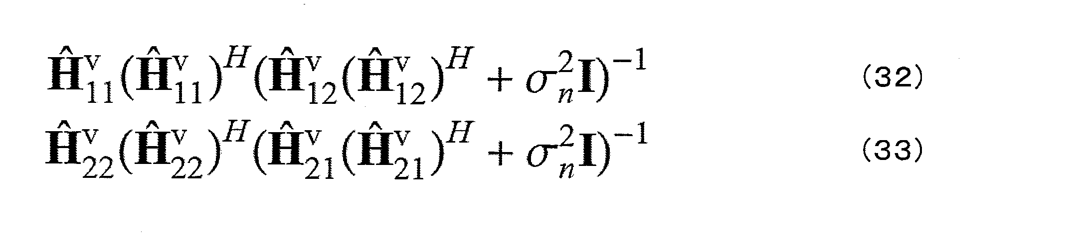
なお、式(32)では、端末装置101における受信重みを求めることができる。式(33)では、基地局装置100-1に接続している端末装置(図示せず)における受信重みを求めることができる。
基地局装置は、受信重みを想定した送信重みを求めることもできる。このとき、基地局装置は、送信重みを想定した受信重みを求めることもできる。さらに送信重みと受信重みを交互に求めることを繰り返すと、干渉抑圧性能を向上させることができる。なお、送信重みや受信重みの初期値は、任意に設定して良いし、また、互いの重みを考慮しない場合の重みを用いることもできる。また、送信重み、受信重みは、チャネルの共分散行列を用いて求めることができる。
なお、本実施形態では、各基地局装置で全ての送信重みと受信重みを求める場合を説明したが、本発明はこれに限らず、1つの基地局装置で全ての送信重みと受信重みを求めてから各基地局装置に必要な重みを通知することもできる。また、基地局装置は、求めた受信重みを端末装置に通知しても良いし、基地局装置が端末装置に通知せずに、端末装置で求めても良い。
送受信重みは、基地局装置100-2からの干渉信号を抑圧する。基地局装置100-1からの干渉信号は、第1の実施形態と同様に干渉除去することもできるし、第2の実施形態と同様に最尤検出することもできる。
このように第3の実施形態では、端末装置は、干渉ストリームのうち、同一セル内のストリームを検出及び除去し、セル間干渉ストリームについては送信重み、又は、送信重み及び受信重みを用いて抑圧する方法を説明した。従って、全ての干渉ストリームが検出できない場合であっても、干渉を抑圧することが可能となり、スループットを向上させることができる。
なお、上記第1から3の実施形態では、1つの基地局装置からの干渉信号を検出及び除去する場合を説明したが、本発明はこれに限らず、複数の基地局装置から干渉信号が到来する場合であっても本発明を適用することができる。
なお、上記第1から3の実施形態では、1つの基地局装置からの干渉信号を重みを用いて抑圧していたが、本発明はこれに限らず、複数の基地局装置からの干渉信号を抑圧する場合であっても本発明を適用することができる。
なお、上記第1から3の実施形態では、1つのセル内で2つ端末装置が空間多重されている場合を説明したが、本発明はこれに限らず、3以上の端末装置が空間多重されていても良い。その場合、端末装置は、セル内で2以上の端末装置宛信号による干渉を検出及び除去することができる。なお、端末装置は、セル内の全ての干渉ストリームを検出及び除去しなくても良く、一部の干渉ストリームを検出及び除去すれば良い。
なお、本発明に係る基地局装置及び移動局装置で動作するプログラムは、本発明に関わる上記実施形態の機能を実現するように、CPU等を制御するプログラム(コンピュータを機能させるプログラム)である。そして、これら装置で取り扱われる情報は、その処理時に一時的にRAMに蓄積され、その後、各種ROMやHDDに格納され、必要に応じてCPUによって読み出し、修正・書き込みが行われる。プログラムを格納する記録媒体としては、半導体媒体(例えば、ROM、不揮発性メモリカード等)、光記録媒体(例えば、DVD、MO、MD、CD、BD等)、磁気記録媒体(例えば、磁気テープ、フレキシブルディスク等)等のいずれであっても良い。また、ロードしたプログラムを実行することにより、上述した実施形態の機能が実現されるだけでなく、そのプログラムの指示に基づき、オペレーティングシステムあるいは他のアプリケーションプログラム等と共同して処理することにより、本発明の機能が実現される場合もある。
また市場に流通させる場合には、可搬型の記録媒体にプログラムを格納して流通させたり、インターネット等のネットワークを介して接続されたサーバコンピュータに転送したりすることができる。この場合、サーバコンピュータの記憶装置も本発明に含まれる。また、上述した実施形態における移動局装置および基地局装置の一部、または全部を典型的には集積回路であるLSIとして実現しても良い。受信装置の各機能ブロックは個別にチップ化しても良いし、一部、または全部を集積してチップ化しても良い。各機能ブロックを集積回路化した場合に、それらを制御する集積回路制御部が付加される。
また、集積回路化の手法はLSIに限らず専用回路、または汎用プロセッサで実現しても良い。また、半導体技術の進歩によりLSIに代替する集積回路化の技術が出現した場合、当該技術による集積回路を用いることも可能である。
なお、本願発明は上述の実施形態に限定されるものではない。本願発明の端末装置は、移動局装置への適用に限定されるものではなく、屋内外に設置される据え置き型、または非可動型の電子機器、例えば、AV機器、キッチン機器、掃除・洗濯機器、空調機器、オフィス機器、自動販売機、その他生活機器などに適用出来ることは言うまでもない。
以上、この発明の実施形態を、図面を参照して詳述してきたが、具体的な構成はこの実施形態に限られるものではなく、この発明の要旨を逸脱しない範囲の設計等も特許請求の範囲に含まれる。
本発明は、端末装置及び受信方法に用いて好適である。
100-1、100-2 基地局装置
101、102 端末装置
201、307、701 上位レイヤ
202-1~202-U、702-1~702-U 符号化部
203-1~203-U、703-1~703-U スクランブル部
204-1~204-U、704-1~704-U 変調部
205、705 レイヤマッピング部
206、308、707 参照信号生成部
207、708 プレコーディング部
208、709 端末情報生成部
209-1~209-T、710-1~710-T リソースマッピング部
210-1~210-T、711-1~711-T OFDM信号生成部
211-1~211-T、310-1~310-T、712-1~712-T 送信部
212-1~212-T、311-1~311-T、713-1~713-T 送信アンテナ
213-1~213-R、301-1~301-R、714-1~714-R 受信アンテナ
214-1~214-R、302-1~302-R、715-1~715-R 受信部
215、716 報告情報検出部
303-1~303-R CP除去部
304-1~304-R FFT部
305 チャネル推定部
306 信号検出部
309 上りリンク信号生成部
401、406 伝搬路補償部
402 復調部
403 デスクランブル部
404 復号部
405 干渉除去部
501 プレフィルタ部
502 最尤検出部
503-1~503-N デスクランブル部
504-1~504-N 復号部
706 重み生成部
101、102 端末装置
201、307、701 上位レイヤ
202-1~202-U、702-1~702-U 符号化部
203-1~203-U、703-1~703-U スクランブル部
204-1~204-U、704-1~704-U 変調部
205、705 レイヤマッピング部
206、308、707 参照信号生成部
207、708 プレコーディング部
208、709 端末情報生成部
209-1~209-T、710-1~710-T リソースマッピング部
210-1~210-T、711-1~711-T OFDM信号生成部
211-1~211-T、310-1~310-T、712-1~712-T 送信部
212-1~212-T、311-1~311-T、713-1~713-T 送信アンテナ
213-1~213-R、301-1~301-R、714-1~714-R 受信アンテナ
214-1~214-R、302-1~302-R、715-1~715-R 受信部
215、716 報告情報検出部
303-1~303-R CP除去部
304-1~304-R FFT部
305 チャネル推定部
306 信号検出部
309 上りリンク信号生成部
401、406 伝搬路補償部
402 復調部
403 デスクランブル部
404 復号部
405 干渉除去部
501 プレフィルタ部
502 最尤検出部
503-1~503-N デスクランブル部
504-1~504-N 復号部
706 重み生成部
Claims (4)
- 第1の基地局装置と接続している端末装置であって、
第1の基地局装置からのユーザ間干渉である第1の干渉信号と、第2の基地局装置からのセル間干渉である第2の干渉信号とを受信し、
前記第1の干渉信号のうち少なくとも1つの干渉ストリームは前記第1の基地局装置から送信される端末情報を用いて復調し、前記第2の干渉信号は受信重みを用いて抑圧する端末装置。 - 前記第2の基地局装置は複数である請求項1に記載の端末装置。
- 前記第2の干渉信号を抑圧した後に前記第1の干渉信号を抑圧する請求項1に記載の端末装置。
- 第1の基地局装置と接続している端末装置における受信方法であって、
第1の基地局装置からのユーザ間干渉である第1の干渉信号と、第2の基地局装置からのセル間干渉である第2の干渉信号とを受信し、
前記第1の干渉信号のうち少なくとも1つの干渉ストリームは前記第1の基地局装置から送信される端末情報を用いて復調し、前記第2の干渉信号は受信重みを用いて抑圧する受信方法。
Priority Applications (1)
| Application Number | Priority Date | Filing Date | Title |
|---|---|---|---|
| US14/901,973 US9979504B2 (en) | 2013-07-03 | 2014-06-19 | Terminal device, and reception method |
Applications Claiming Priority (2)
| Application Number | Priority Date | Filing Date | Title |
|---|---|---|---|
| JP2013-139355 | 2013-07-03 | ||
| JP2013139355A JP2016157991A (ja) | 2013-07-03 | 2013-07-03 | 端末装置、基地局装置及び受信方法 |
Publications (1)
| Publication Number | Publication Date |
|---|---|
| WO2015001982A1 true WO2015001982A1 (ja) | 2015-01-08 |
Family
ID=52143560
Family Applications (1)
| Application Number | Title | Priority Date | Filing Date |
|---|---|---|---|
| PCT/JP2014/066338 Ceased WO2015001982A1 (ja) | 2013-07-03 | 2014-06-19 | 端末装置及び受信方法 |
Country Status (3)
| Country | Link |
|---|---|
| US (1) | US9979504B2 (ja) |
| JP (1) | JP2016157991A (ja) |
| WO (1) | WO2015001982A1 (ja) |
Families Citing this family (5)
| Publication number | Priority date | Publication date | Assignee | Title |
|---|---|---|---|---|
| US10033482B2 (en) * | 2016-08-03 | 2018-07-24 | Samsung Electronics Co., Ltd | System and method for providing interference parameter estimation for multi-input multi-output (MIMO) communication system |
| JP6719085B2 (ja) * | 2016-10-18 | 2020-07-08 | パナソニックIpマネジメント株式会社 | 端末及び通信方法 |
| WO2021029067A1 (ja) * | 2019-08-15 | 2021-02-18 | 株式会社Nttドコモ | 端末及び通信方法 |
| CN112383330B (zh) * | 2020-11-03 | 2022-02-08 | 上海擎昆信息科技有限公司 | Mu-mimo信号检测方法及装置、设备、存储介质 |
| US11228359B1 (en) * | 2021-01-05 | 2022-01-18 | Ceva D.S.P. Ltd. | System and method for performing MLD preprocessing in a MIMO decoder |
Citations (4)
| Publication number | Priority date | Publication date | Assignee | Title |
|---|---|---|---|---|
| JP2012090269A (ja) * | 2010-10-18 | 2012-05-10 | Ntt Docomo Inc | 1つ以上の干渉信号の存在下で送信される所望の信号を復元する方法及び受信機 |
| JP2012204909A (ja) * | 2011-03-24 | 2012-10-22 | Sharp Corp | 基地局、端末、通信システムおよび通信方法 |
| WO2012144620A1 (ja) * | 2011-04-22 | 2012-10-26 | 株式会社エヌ・ティ・ティ・ドコモ | 受信機、データ受信方法、ならびにチャネル推定装置およびその方法 |
| JP2013009290A (ja) * | 2011-05-20 | 2013-01-10 | Ntt Docomo Inc | 受信装置、送信装置及び無線通信方法 |
Family Cites Families (4)
| Publication number | Priority date | Publication date | Assignee | Title |
|---|---|---|---|---|
| KR20060115293A (ko) * | 2005-05-04 | 2006-11-08 | 삼성전자주식회사 | Ofdma 방식의 시스템에서 채널의 구성 및 운용 방법과송수신 장치 및 방법 |
| JP5432208B2 (ja) * | 2011-04-25 | 2014-03-05 | 株式会社Nttドコモ | 移動通信端末 |
| JP5874820B2 (ja) * | 2012-05-11 | 2016-03-02 | 富士通株式会社 | 移動局および無線通信方法 |
| KR102061700B1 (ko) * | 2012-11-02 | 2020-01-02 | 삼성전자주식회사 | 무선 통신 시스템에서 간섭 인지 검출 방법 및 장치 |
-
2013
- 2013-07-03 JP JP2013139355A patent/JP2016157991A/ja active Pending
-
2014
- 2014-06-19 WO PCT/JP2014/066338 patent/WO2015001982A1/ja not_active Ceased
- 2014-06-19 US US14/901,973 patent/US9979504B2/en not_active Expired - Fee Related
Patent Citations (4)
| Publication number | Priority date | Publication date | Assignee | Title |
|---|---|---|---|---|
| JP2012090269A (ja) * | 2010-10-18 | 2012-05-10 | Ntt Docomo Inc | 1つ以上の干渉信号の存在下で送信される所望の信号を復元する方法及び受信機 |
| JP2012204909A (ja) * | 2011-03-24 | 2012-10-22 | Sharp Corp | 基地局、端末、通信システムおよび通信方法 |
| WO2012144620A1 (ja) * | 2011-04-22 | 2012-10-26 | 株式会社エヌ・ティ・ティ・ドコモ | 受信機、データ受信方法、ならびにチャネル推定装置およびその方法 |
| JP2013009290A (ja) * | 2011-05-20 | 2013-01-10 | Ntt Docomo Inc | 受信装置、送信装置及び無線通信方法 |
Non-Patent Citations (5)
| Title |
|---|
| "Technical Specification Group Radio Access Network; Network-Assisted Interference Cancellation and Suppression for LTE (Release 12", 3GPP TSG-RAN WG1 MEETING #75, 16 January 2014 (2014-01-16) * |
| ERICSSON ET AL.: "NAIC Reference receivers", 3GPP TSG-RAN WG4 MEETING #66BIS, R4-131643, 15 April 2013 (2013-04-15) * |
| MANABU MIKAMI ET AL.: "A Study on Multi- cell /Multi-user MIMO Transmission with Whitening Filter at both Base and Mobile Stations", IEICE TECHNICAL REPORT, 17 November 2005 (2005-11-17) * |
| MITSUKI YAMADA ET AL.: "Evaluation of Non-transparent/Transparent MU-MIMO in the Presence of Inter Cell Interference", THE INSTITUTE OF ELECTRONICS, INFORMATION AND COMMUNICATION ENGINEERS SOGO TAIKAI KOEN RONBUNSHU, 28 February 2011 (2011-02-28), pages 453 * |
| SUGURU OKUYAMA ET AL.: "Iterative MMSE Spatial Filtering for uplink SC-FDMA", IEICE TECHNICAL REPORT, 10 June 2010 (2010-06-10) * |
Also Published As
| Publication number | Publication date |
|---|---|
| US20160373204A1 (en) | 2016-12-22 |
| JP2016157991A (ja) | 2016-09-01 |
| US9979504B2 (en) | 2018-05-22 |
Similar Documents
| Publication | Publication Date | Title |
|---|---|---|
| EP2966885B1 (en) | Terminal device, base station device, communication system, reception method, transmission method, and communication method | |
| EP3042462B1 (en) | Device and method of enhancing downlink ue-specific demodulation reference signal to facilitate inter -cell interference supression | |
| US11362757B2 (en) | Apparatus including a transmission processing unit that generates transmission signal sequences of multiple power layers | |
| JP6956006B2 (ja) | 基地局装置、端末装置、および通信方法 | |
| JP2017531363A (ja) | 無線通信システムで干渉信号除去及び抑制を用いたダウンリンクデータ受信方法及び装置 | |
| US9276647B2 (en) | Base station device and mobile station device used in cooperative communications | |
| WO2015001982A1 (ja) | 端末装置及び受信方法 | |
| WO2016052031A1 (ja) | 基地局装置および端末装置 | |
| US20160057760A1 (en) | Base station apparatus, terminal apparatus, and communication system | |
| CN112887068A (zh) | 数据传输方法、发送设备和接收设备 | |
| US20160373195A1 (en) | Terminal device, base station apparatus, and transmission method | |
| US20150146559A1 (en) | Transmission apparatus, reception apparatus, transmission method, and reception method | |
| WO2016074897A1 (en) | A method and apparatus for interference cancellation | |
| WO2015001981A1 (ja) | 端末装置、基地局装置及び受信方法 | |
| JP2014204254A (ja) | 端末装置、基地局装置、無線通信システムおよび通信方法 | |
| WO2015016193A1 (ja) | 端末装置、基地局装置及び受信方法 | |
| JP2017034294A (ja) | 基地局装置、端末装置、送信方法及び受信方法 | |
| JP2014135529A (ja) | 基地局装置、通信システム、送信方法及び通信方法 | |
| JP2014154916A (ja) | 基地局装置、端末装置、通信システム、送信方法及び通信方法 | |
| JP2014187472A (ja) | 基地局装置、端末装置、通信システム、送信方法、受信方法及び通信方法 | |
| JP2015122546A (ja) | 通信システム及び通信方法 |
Legal Events
| Date | Code | Title | Description |
|---|---|---|---|
| 121 | Ep: the epo has been informed by wipo that ep was designated in this application |
Ref document number: 14819921 Country of ref document: EP Kind code of ref document: A1 |
|
| WWE | Wipo information: entry into national phase |
Ref document number: 14901973 Country of ref document: US |
|
| NENP | Non-entry into the national phase |
Ref country code: DE |
|
| NENP | Non-entry into the national phase |
Ref country code: JP |
|
| 122 | Ep: pct application non-entry in european phase |
Ref document number: 14819921 Country of ref document: EP Kind code of ref document: A1 |