WO2015001919A1 - Inkjet recording device - Google Patents
Inkjet recording device Download PDFInfo
- Publication number
- WO2015001919A1 WO2015001919A1 PCT/JP2014/065283 JP2014065283W WO2015001919A1 WO 2015001919 A1 WO2015001919 A1 WO 2015001919A1 JP 2014065283 W JP2014065283 W JP 2014065283W WO 2015001919 A1 WO2015001919 A1 WO 2015001919A1
- Authority
- WO
- WIPO (PCT)
- Prior art keywords
- printing
- nozzle
- print head
- abnormal
- Prior art date
Links
Images
Classifications
-
- B—PERFORMING OPERATIONS; TRANSPORTING
- B41—PRINTING; LINING MACHINES; TYPEWRITERS; STAMPS
- B41J—TYPEWRITERS; SELECTIVE PRINTING MECHANISMS, i.e. MECHANISMS PRINTING OTHERWISE THAN FROM A FORME; CORRECTION OF TYPOGRAPHICAL ERRORS
- B41J2/00—Typewriters or selective printing mechanisms characterised by the printing or marking process for which they are designed
- B41J2/005—Typewriters or selective printing mechanisms characterised by the printing or marking process for which they are designed characterised by bringing liquid or particles selectively into contact with a printing material
- B41J2/01—Ink jet
- B41J2/21—Ink jet for multi-colour printing
- B41J2/2132—Print quality control characterised by dot disposition, e.g. for reducing white stripes or banding
- B41J2/2139—Compensation for malfunctioning nozzles creating dot place or dot size errors
-
- B—PERFORMING OPERATIONS; TRANSPORTING
- B41—PRINTING; LINING MACHINES; TYPEWRITERS; STAMPS
- B41J—TYPEWRITERS; SELECTIVE PRINTING MECHANISMS, i.e. MECHANISMS PRINTING OTHERWISE THAN FROM A FORME; CORRECTION OF TYPOGRAPHICAL ERRORS
- B41J2/00—Typewriters or selective printing mechanisms characterised by the printing or marking process for which they are designed
- B41J2/005—Typewriters or selective printing mechanisms characterised by the printing or marking process for which they are designed characterised by bringing liquid or particles selectively into contact with a printing material
- B41J2/01—Ink jet
- B41J2/015—Ink jet characterised by the jet generation process
- B41J2/02—Ink jet characterised by the jet generation process generating a continuous ink jet
- B41J2/03—Ink jet characterised by the jet generation process generating a continuous ink jet by pressure
-
- B—PERFORMING OPERATIONS; TRANSPORTING
- B41—PRINTING; LINING MACHINES; TYPEWRITERS; STAMPS
- B41J—TYPEWRITERS; SELECTIVE PRINTING MECHANISMS, i.e. MECHANISMS PRINTING OTHERWISE THAN FROM A FORME; CORRECTION OF TYPOGRAPHICAL ERRORS
- B41J2/00—Typewriters or selective printing mechanisms characterised by the printing or marking process for which they are designed
- B41J2/005—Typewriters or selective printing mechanisms characterised by the printing or marking process for which they are designed characterised by bringing liquid or particles selectively into contact with a printing material
- B41J2/01—Ink jet
- B41J2/07—Ink jet characterised by jet control
- B41J2/075—Ink jet characterised by jet control for many-valued deflection
- B41J2/08—Ink jet characterised by jet control for many-valued deflection charge-control type
-
- B—PERFORMING OPERATIONS; TRANSPORTING
- B41—PRINTING; LINING MACHINES; TYPEWRITERS; STAMPS
- B41J—TYPEWRITERS; SELECTIVE PRINTING MECHANISMS, i.e. MECHANISMS PRINTING OTHERWISE THAN FROM A FORME; CORRECTION OF TYPOGRAPHICAL ERRORS
- B41J2/00—Typewriters or selective printing mechanisms characterised by the printing or marking process for which they are designed
- B41J2/005—Typewriters or selective printing mechanisms characterised by the printing or marking process for which they are designed characterised by bringing liquid or particles selectively into contact with a printing material
- B41J2/01—Ink jet
- B41J2/07—Ink jet characterised by jet control
- B41J2/075—Ink jet characterised by jet control for many-valued deflection
- B41J2/095—Ink jet characterised by jet control for many-valued deflection electric field-control type
Abstract
In a device with two or more nozzles which are retained within a print head, and which are operated to carry out printing of a single item of printed material, a situation may occur in which, despite a given nozzle becoming unable to continue printing due to the occurrence of a malfunction, the other nozzles are fine. In such a case, particularly when the customer is printing a printed material that does not permit the conveyor line to be quickly halted, considerable printing wastage is produced, despite the presence of nozzles which are able to print, resulting in the problem that the product production schedule is affected. To solve the aforementioned problem, when printing by operating two or more nozzles, in the event that a given nozzle is unable to continue printing due to the occurrence of a malfunction, control is carried out in such a way that printed content that should have been printed by the nozzle that is unable to continue printing is printed by other, normal nozzles. Through the use of the present invention, printing can continue without quickly halting the conveyor line, even when a malfunction has occurred in a given nozzle.
Description
本発明は、インクジェット記録装置に関し、特に2個以上のノズルを有したインクジェット記録装置において、ノズル異常に対応したインクジェット記録装置に関する。
The present invention relates to an ink jet recording apparatus, and more particularly to an ink jet recording apparatus corresponding to a nozzle abnormality in an ink jet recording apparatus having two or more nozzles.
本技術分野の背景技術として、特開2010-137528(特許文献1)がある。この文献には、「2個のノズルを有するインクジェット記録装置において、各々のノズルで印字した文字の縦方向の間隔を調整可能にするための技術を提供する」制御が記載されている。
As a background art in this technical field, there is JP 2010-137528 (Patent Document 1). This document describes control that “in an inkjet recording apparatus having two nozzles, provides a technique for making it possible to adjust the vertical spacing of characters printed by each nozzle”.
2個以上のノズルを用いて1つの印字物に対して印字を行うインクジェット記録装置においては、ノズルごとにインクを噴出して印字を実行するため、インクジェット記録装置はノズルそれぞれに対して制御を行う必要がある。しかし、すべてのノズルの状態は必ずしも同一となるとは限らず、あるノズルに異常が発生したことにより印字続行できなくなったときでも、それ以外のノズルが正常であることは十分起こりえる。この場合、特に搬送ラインをすぐに止めることのできない印字物(ケーブル・パイプなど)に印字する顧客にとっては、印字できるノズルがあるにも関わらず、異常ノズルによる影響で印字無駄を多く生成してしまうという課題があった。
特許文献1には、その点について考慮されていなかった。 In an ink jet recording apparatus that performs printing on one printed matter using two or more nozzles, the ink jet recording apparatus performs printing by ejecting ink for each nozzle. Therefore, the ink jet recording apparatus controls each nozzle. There is a need. However, the state of all nozzles is not necessarily the same, and even when printing cannot be continued due to an abnormality in a certain nozzle, it is possible that other nozzles are normal. In this case, especially for customers who print on printed matter (cables, pipes, etc.) that cannot immediately stop the conveyance line, a lot of printing waste is generated due to the influence of abnormal nozzles even though there are nozzles that can print. There was a problem of ending up.
Patent Document 1 does not consider this point.
特許文献1には、その点について考慮されていなかった。 In an ink jet recording apparatus that performs printing on one printed matter using two or more nozzles, the ink jet recording apparatus performs printing by ejecting ink for each nozzle. Therefore, the ink jet recording apparatus controls each nozzle. There is a need. However, the state of all nozzles is not necessarily the same, and even when printing cannot be continued due to an abnormality in a certain nozzle, it is possible that other nozzles are normal. In this case, especially for customers who print on printed matter (cables, pipes, etc.) that cannot immediately stop the conveyance line, a lot of printing waste is generated due to the influence of abnormal nozzles even though there are nozzles that can print. There was a problem of ending up.
2個以上のノズルを操作して印字するとき、あるノズルに異常が発生したことにより印字続行できなくなった場合には、それ以外の正常なノズルで、印字続行できないノズルが印字すべき印字内容を印字するように制御を行う。
When printing by operating two or more nozzles, if it becomes impossible to continue printing due to an abnormality in one nozzle, the other nozzles that cannot continue printing with other normal nozzles will be Control to print.
あるノズルに異常が発生したとしても搬送ラインをすぐに止めることなく印字を続行することができる。
Even if an abnormality occurs in a certain nozzle, printing can be continued without immediately stopping the transport line.
以下実施例では、説明を簡単にするために、印字ヘッド内に2個のノズルを保有し(以下、この印字ヘッドをツインノズルと呼ぶ)、これらを操作して1つの印字物に対して印字を実行する装置についての説明を行う。
In the following embodiments, for simplicity of explanation, the print head has two nozzles (hereinafter, this print head is referred to as a twin nozzle), and these are operated to print on one printed matter. An apparatus for executing the above will be described.
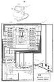
図1(A)は、一般的なインクジェット記録装置の全体図である。1はインクジェット記録装置、18はディスプレイ、21は印字ヘッドである。また、図1(B)に、インクジェット記録装置1の機能ブロック図を示す。インクジェット記録装置1は、大きく分けて、コントローラAと印字装置Bから構成され、搬送ライン6上にある被印字物である製品7に対して印字を行う。
FIG. 1A is an overall view of a general ink jet recording apparatus. Reference numeral 1 denotes an ink jet recording apparatus, 18 denotes a display, and 21 denotes a print head. FIG. 1B shows a functional block diagram of the inkjet recording apparatus 1. The ink jet recording apparatus 1 is roughly composed of a controller A and a printing apparatus B, and performs printing on a product 7 that is a printing object on the transport line 6.
インクジェット記録装置1は、入力部2から得た情報を、制御装置8を有する制御部3と、メモリ9およびプログラム格納装置10を有する記憶部4で解析し、最適な印字結果を得られるよう必要な制御信号補正を行って出力信号を出力部5より送信する。また、コントローラAの入力部2で被印字物センサ11からの信号を受信する被印字物検知装置12、エンコーダ13からの信号を受信する搬送速度検知装置14、オペレータによる入力信号を受信する入力装置15により印字装置Bや製品の情報を入力し、上記制御部3で演算処理して出力部5から印字装置Bに対し出力信号を発信している。
The ink jet recording apparatus 1 needs to analyze the information obtained from the input unit 2 in the control unit 3 having the control unit 8 and the storage unit 4 having the memory 9 and the program storage unit 10 so as to obtain an optimum printing result. The control signal is corrected and the output signal is transmitted from the output unit 5. Further, the printing object detection device 12 that receives a signal from the printing material sensor 11 at the input unit 2 of the controller A, the conveyance speed detection device 14 that receives a signal from the encoder 13, and an input device that receives an input signal from an operator. 15, information on the printing apparatus B and the product is input, and calculation processing is performed by the control unit 3, and an output signal is transmitted from the output unit 5 to the printing apparatus B.
印字を行う際の印字データや各種印字条件を設定し変更するときは、印字装置Bの入力手段としてのタッチパネル16からコントローラAの入力装置15に入力した設定値を、記憶部4のメモリ9で記憶するとともに制御部3の制御装置8で演算処理し、表示装置17を介してディスプレイ18で表示する。
When setting and changing the print data and various printing conditions for printing, the setting value input to the input device 15 of the controller A from the touch panel 16 as the input means of the printing device B is stored in the memory 9 of the storage unit 4. The information is stored and processed by the control device 8 of the control unit 3 and displayed on the display 18 via the display device 17.
搬送ライン6上にある製品7に対して印字を開始するときは、被印字物検知装置12および搬送速度検知装置14で製品7の位置を特定する。次にインク容器19からポンプ20によって供給されたインクを、印字ヘッド21内のノズル22を励振電圧発生装置23で励振してインク粒子24を形成し、メモリ9上の印字データに合わせて帯電電圧発生装置25で帯電電極26に帯電電圧をかける。荷電されたインク粒子24は、偏向電圧発生装置27の電圧を印加した偏向電極28を通過するときに偏向し、製品7に対して印字ドットを形成し印字を行う。このとき、帯電電極26はインク粒子24に対して常に同じ方向の電荷を付加しており、偏向電極28は常に同じ電圧を印加しているので、印字ドットの偏向方向は常に上方に偏向する。荷電されないインク粒子24は印字に使用されずにガター59により回収されインク容器19に戻る。また、印字ヘッド21の状態について、図示しないセンサからなる検知部の出力である制御信号29で常に監視しており、印字ヘッド21の各要素(ノズル22、帯電電極26、偏向電極28)に異常があった場合には、インクジェット記録装置1は即時に異常対応処理を行う。
When printing on the product 7 on the transport line 6 is started, the position of the product 7 is specified by the printed material detection device 12 and the transport speed detection device 14. Next, the ink supplied from the ink container 19 by the pump 20 is excited by the excitation voltage generator 23 at the nozzle 22 in the print head 21 to form ink particles 24, and the charging voltage is adjusted in accordance with the print data on the memory 9. The generator 25 applies a charging voltage to the charging electrode 26. The charged ink particles 24 are deflected when passing through the deflection electrode 28 to which the voltage of the deflection voltage generator 27 is applied, and a printing dot is formed on the product 7 to perform printing. At this time, the charging electrode 26 always applies the same direction of charge to the ink particles 24, and the deflection electrode 28 always applies the same voltage, so that the deflection direction of the print dots is always deflected upward. The ink particles 24 that are not charged are not used for printing but are collected by the gutter 59 and returned to the ink container 19. Further, the state of the print head 21 is constantly monitored by a control signal 29 which is an output of a detection unit including a sensor (not shown), and each element (nozzle 22, charging electrode 26, deflection electrode 28) of the print head 21 is abnormal. If there is, the ink jet recording apparatus 1 immediately performs an abnormality handling process.
その他、装置電源30の状態は電源装置31にて管理しており、外部接続端子32の状態は接続装置33にて管理している。
In addition, the state of the device power supply 30 is managed by the power supply device 31, and the state of the external connection terminal 32 is managed by the connection device 33.
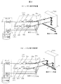
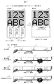
図2は、ツインノズルのときの印字ヘッド21の構成例および印字例を示す。図2(A)、(B)に共通することとして、印字ヘッド21内にはノズル22a(以下、ノズルα)とノズル22b(以下、ノズルβ)が存在し、ノズルαは帯電電極26a、 偏向電極28a、ガター59aを、ノズルβは帯電電極26b、偏向電極28b、ガター59bをそれぞれ使用して印字を行う。ここで、説明の便宜上、ノズル、帯電電極、偏向電極、ガターをひとまとまりとして、サブ印字ヘッドと称する。
FIG. 2 shows a configuration example and a print example of the print head 21 at the time of twin nozzles. 2A and 2B, the print head 21 includes a nozzle 22a (hereinafter referred to as nozzle α) and a nozzle 22b (hereinafter referred to as nozzle β). The nozzle α includes a charging electrode 26a and a heel deflection. Printing is performed using the electrode 28a and the gutter 59a, and the nozzle β using the charging electrode 26b, the deflection electrode 28b and the gutter 59b. Here, for convenience of explanation, a nozzle, a charging electrode, a deflection electrode, and a gutter are collectively referred to as a sub print head.
インクジェット記録装置は、ノズルαとノズルβの制御を独立して行っており、ノズルαとノズルβの印字内容や印字設定値もそれぞれ異なるため、独立した動作を行う。ここで、ノズルαとノズルβの配置は縦方向に配置する方法と横方向に配置する方法が考えられる。縦方向に配置する方法では、図2(A)に示すように、偏向電極28a、28bが縦方向に配置しているため、印字例7(A)に示すように、縦方向にある文字を同時に印字することができる。また、横方向に配置する方法では、図2(B)に示すように、偏向電極28a、28bが横方向に配置しているため、印字例7(B)に示すように、横方向にある文字を同時に印字することができる。
The ink jet recording apparatus controls the nozzle α and the nozzle β independently, and the print contents and print set values of the nozzle α and the nozzle β are different from each other. Here, the arrangement of the nozzle α and the nozzle β may be a vertical arrangement method or a horizontal arrangement method. In the method of arranging in the vertical direction, as shown in FIG. 2A, since the deflection electrodes 28a and 28b are arranged in the vertical direction, characters in the vertical direction are displayed as shown in the printing example 7A. You can print at the same time. Further, in the method of arranging in the horizontal direction, as shown in FIG. 2B, the deflection electrodes 28a and 28b are arranged in the horizontal direction, so that they are in the horizontal direction as shown in the printing example 7B. Characters can be printed simultaneously.
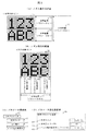
図3は、ツインノズルで印字する際に、インクジェット記録装置が必要とする各種印字パラメータの一例を示す図である。
FIG. 3 is a diagram showing an example of various printing parameters required by the ink jet recording apparatus when printing with twin nozzles.
本実施例では、ツインノズルにおいて、一つのノズルが異常となった場合に、残る正常なノズルで異常ノズルが印字すべき印字内容を印字するように制御を行う。その際に必要な印字パラメータの関係を示した図である。
In this embodiment, when one nozzle becomes abnormal in the twin nozzle, control is performed so that the remaining nozzles print the content to be printed by the abnormal nozzle. FIG. 6 is a diagram illustrating a relationship of necessary print parameters at that time.
ここで、ノズル異常とは、そのノズルを含む帯電電極、偏向電極、ガターをひとまとまりとしたサブ印字ヘッドが異常であることをいい、その異常に起因するノズルから出たインク粒子が対象製品に正確に印字されない状態をいう。以降、サブ印字ヘッドが異常であることをノズル異常と称して説明する。異常の原因としては、ノズルの目詰まり、帯電電極における帯電電荷量が規定値と異なる場合等がある。また、異常検知の方法としては、図1で説明したように、印字ヘッド21の各要素(ノズル22、帯電電極26、偏向電極28)に異常があるかを、それぞれのセンサ出力である制御信号29を用いて常に監視することで検知している。
Here, the nozzle abnormality means that the sub print head including the charging electrode, deflection electrode, and gutter including the nozzle is abnormal, and the ink particles emitted from the nozzle due to the abnormality are included in the target product. A state in which printing is not performed accurately. Hereinafter, the abnormality of the sub print head will be described as nozzle abnormality. Causes of the abnormality include clogging of the nozzle and a case where the charged charge amount at the charging electrode is different from a specified value. Further, as described in FIG. 1, as a method for detecting an abnormality, whether or not each element (nozzle 22, charging electrode 26, deflection electrode 28) of the print head 21 is abnormal is a control signal that is a sensor output. It is detected by constantly monitoring using 29.
図3(A)は、ノズルαとノズルβを縦方向に配置した場合の印字内容34と、その印字範囲を示した図であり、図3(B)は、ノズルαとノズルβを横方向に配置した場合の印字内容38と、その印字範囲を示した図である。また、図3(C)は、印字パラメータの構成例、図3(D)は、印字パラメータ設定画面例を示す。
3A is a diagram showing the print contents 34 and the print range when the nozzle α and the nozzle β are arranged in the vertical direction, and FIG. 3B is a diagram showing the nozzle α and the nozzle β in the horizontal direction. FIG. 6 is a diagram showing the print contents 38 and the print range when they are arranged. FIG. 3C shows a configuration example of print parameters, and FIG. 3D shows a print parameter setting screen example.
図3(A)では、ノズルαが印字する印字範囲(パラメータL1)35と、ノズルβが印字する印字範囲(パラメータM1)36は、縦方向に異なる。また、全体を印字する印字範囲(パラメータN1)37は、印字範囲(パラメータL1)35と印字範囲(パラメータM1)36を合わせたものである。すなわち、一つのノズルが異常となった場合に、残る正常なノズルで異常ノズルが印字すべき印字内容を印字するときには、印字範囲(パラメータN1)37を使用して、印字制御を行う。よって、印字内容34は、印字範囲(パラメータL1)35と印字範囲(パラメータM1)36を組合せたもの、または、印字範囲(パラメータN1)37のいずれでも印字できるように設定されている。
In FIG. 3A, the print range (parameter L1) 35 printed by the nozzle α and the print range (parameter M1) 36 printed by the nozzle β are different in the vertical direction. The print range (parameter N1) 37 for printing the whole is a combination of the print range (parameter L1) 35 and the print range (parameter M1) 36. That is, when one nozzle becomes abnormal, when printing contents to be printed by the abnormal nozzles with the remaining normal nozzles, printing control is performed using the printing range (parameter N1) 37. Accordingly, the print content 34 is set so that printing can be performed using either a combination of the print range (parameter L1) 35 and the print range (parameter M1) 36 or a print range (parameter N1) 37.
図3(B)では、ノズルαが印字する印字範囲(パラメータL2)39と、ノズルβが印字する印字範囲(パラメータM2)40は、横方向に異なる。また、全体を印字する印字範囲(パラメータN2)41は、印字範囲(パラメータL2)39と印字範囲(パラメータM2)40を合わせたものである。すなわち、一つのノズルが異常となった場合に、残る正常なノズルで異常ノズルが印字すべき印字内容を印字するときには、印字範囲(パラメータN2)41を使用して、印字制御を行う。よって、印字内容38は、印字範囲(パラメータL2)39と印字範囲(パラメータM2)40を組合せたもの、または、印字範囲(パラメータN2)41のいずれでも印字できるように設定されている。
3B, the printing range (parameter L2) 39 printed by the nozzle α and the printing range (parameter M2) 40 printed by the nozzle β are different in the horizontal direction. The print range (parameter N2) 41 for printing the whole is a combination of the print range (parameter L2) 39 and the print range (parameter M2) 40. In other words, when one nozzle becomes abnormal and the remaining normal nozzle prints the print contents to be printed by the abnormal nozzle, the print range (parameter N2) 41 is used to perform print control. Accordingly, the print content 38 is set so that printing can be performed using either a combination of the print range (parameter L2) 39 and the print range (parameter M2) 40 or a print range (parameter N2) 41.
図3(C)に示す印字パラメータ42は、文字サイズ43、文字高さ44、インク粒子使用率45などの種類がある。これらのパラメータは、図3(D)に示す設定画面46に示すように、タッチパネル16から入力し、ディスプレイ18で表示する。図3(D)において、タッチパネル16から入力する際には、例えば、各パラメータの項目と、それらの設定値を増減させるようなボタンが設定されていてもよい。
The print parameters 42 shown in FIG. 3C include types such as a character size 43, a character height 44, and an ink particle usage rate 45. These parameters are input from the touch panel 16 and displayed on the display 18 as shown in the setting screen 46 shown in FIG. In FIG. 3D, when inputting from the touch panel 16, for example, items for each parameter and buttons for increasing / decreasing their set values may be set.
印字パラメータ42を印字内容34や38に使用する際は、その使用範囲は印字範囲ごとに区別される。印字内容34では、印字範囲35・36・37のとき、それぞれの印字パラメータ42はパラメータL1・M1・N1で区別される。印字内容38では、印字範囲39・40・41のとき、それぞれの印字パラメータ42はパラメータL2・M2・N2で区別される。なお、印字パラメータは、メモリ9に記憶され、必要により読み出されて使用される。インクジェット記録装置1では、これら印字パラメータ42を適切に管理して印字に使用する。
When using the print parameter 42 for the print contents 34 and 38, the use range is distinguished for each print range. In the print contents 34, when the print ranges are 35, 36, and 37, the print parameters 42 are distinguished by parameters L1, M1, and N1, respectively. In the print contents 38, when the print ranges are 39, 40, and 41, the print parameters 42 are distinguished by parameters L2, M2, and N2. The print parameters are stored in the memory 9, and are read out and used as necessary. In the ink jet recording apparatus 1, these print parameters 42 are appropriately managed and used for printing.
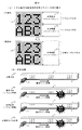
図4は、本実施例による、ツインノズルでノズルが縦方向配置であって、両ノズルが正常時の場合と、いずれかのノズルが異常時の場合の、印字パラメータ割り振りと、それらの印字結果を示した図である。
FIG. 4 shows the assignment of print parameters and the print results when the nozzles are vertically arranged with twin nozzles according to the present embodiment and both nozzles are normal and when either nozzle is abnormal. FIG.
図4(A)において、正常時の印字では、ノズルαが印字範囲35をパラメータL1で印字し、ノズルβが印字範囲36をパラメータM1で印字する。このときの印字結果は、図4(B)の正常印字47となる。ノズルαが異常となった場合には、印字結果は異常印字48のように不正となる。ノズルβが異常となった場合には、同様に、印字結果は異常印字49のように不正となる。これを解決するため、本実施例では、図4(A)の異常時に示すように、一部のノズルが異常となったときには、正常なノズルが印字範囲37をパラメータN1で印字する処理に切換える。その結果、図4(B)の印字結果50となり、異常が発生しても正常時と同じ印字結果となる。
4A, in normal printing, the nozzle α prints the print range 35 with the parameter L1, and the nozzle β prints the print range 36 with the parameter M1. The printing result at this time is normal printing 47 in FIG. When the nozzle α is abnormal, the printing result is incorrect as in the abnormal printing 48. Similarly, when the nozzle β becomes abnormal, the printing result is incorrect as in the abnormal printing 49. In order to solve this, in this embodiment, as shown in FIG. 4A, when some of the nozzles become abnormal, the normal nozzles are switched to the process of printing the print range 37 with the parameter N1. . As a result, the print result 50 shown in FIG. 4B is obtained, and even if an abnormality occurs, the print result is the same as that in the normal state.
図5は、本実施例による、ツインノズルでノズルが横方向配置であって、両ノズルが正常時の場合と、いずれかのノズルが異常時の場合の、印字パラメータ割り振りと、それらの印字結果を示した図である。
FIG. 5 shows the print parameter allocation and the print results when the nozzles are arranged in the horizontal direction in the twin nozzles according to the present embodiment, when both nozzles are normal and when either nozzle is abnormal. FIG.
図5(A)において、正常時の印字では、ノズルαが印字範囲39をパラメータL2で印字し、ノズルβが印字範囲40をパラメータM2で印字する。このときの印字結果は、図5(B)の正常印字51となる。ノズルαが異常となった場合には、印字結果は異常印字52のように不正となる。ノズルβが異常となった場合には、同様に、印字結果は異常印字53のように不正となる。これを解決するため、本実施例では、図5(A)の異常時に示すように、一部のノズルが異常となったときには、正常なノズルが印字範囲41をパラメータN2で印字する処理に切換える。その結果、図5(B)の印字結果54となり、異常が発生しても正常時と同じ印字結果となる。
5A, in normal printing, the nozzle α prints the print range 39 with the parameter L2, and the nozzle β prints the print range 40 with the parameter M2. The printing result at this time is normal printing 51 in FIG. When the nozzle α is abnormal, the printing result is incorrect as in the abnormal printing 52. Similarly, when the nozzle β becomes abnormal, the print result becomes incorrect as in the abnormal print 53. In order to solve this, in this embodiment, as shown in FIG. 5A, when some of the nozzles become abnormal, the normal nozzles are switched to the process of printing the print range 41 with the parameter N2. . As a result, the print result 54 shown in FIG. 5B is obtained, and the same print result as that in the normal state is obtained even if an abnormality occurs.
このように、ノズルが異常となったとき、従来は、印字結果の一部が印字されないため印字無駄を発生させるが、これを防ぐために、正常なノズルでも印字を継続する処理を行なうようにして、あらかじめ全体を印字する印字範囲(37、41)のときの印字パラメータ(N1、N2)を作成しておき、異常発生時に正常なノズルのみでの印字制御に切り替える構成とする。本実施例により、異常が発生しても正常時と同じ印字結果となり、印字無駄の問題について解決を図ることができる。
As described above, when a nozzle becomes abnormal, conventionally, a part of the printing result is not printed, and thus printing is wasted. To prevent this, processing is performed to continue printing even with a normal nozzle. The printing parameters (N1, N2) for the printing range (37, 41) for printing the whole are created in advance, and the control is switched to printing control with only normal nozzles when an abnormality occurs. According to this embodiment, even if an abnormality occurs, the same printing result as that at the normal time is obtained, and the problem of wasteful printing can be solved.
なお、異常発生時に正常なノズルのみでの印字制御に切り替えたとき、その状態をメモリに保存しておき、その状態をインクジェット記録装置の外部へ通知することで、印字制御切り替えに伴う外部対応を容易にすることができる。また、異常発生後から応急的に印字続行できるため、修理完了までの印字できない期間が短くなる。そのため、印字無駄の生成を減らし、顧客の製品開発スケジュールへの影響を抑えることができるという効果がある。
In addition, when switching to printing control with only normal nozzles when an abnormality occurs, the state is stored in the memory, and the state is notified to the outside of the ink jet recording apparatus, so that external correspondence associated with switching of printing control can be performed. Can be easily. In addition, since printing can be continued urgently after the occurrence of an abnormality, the period during which printing cannot be completed until repair is completed is shortened. Therefore, there is an effect that generation of printing waste can be reduced and the influence on the customer's product development schedule can be suppressed.
以上、本実施例では、ツインノズルの場合を想定して説明したが、ノズルを複数個持っている場合について一般形で表現すると、次のようになる。印字に必要なパラメータについて、1つの印字結果を複数のノズルで印字する場合のパラメータ(パラメータX)を一個と、1つの印字結果を異常発生したノズル以外で印字する場合のパラメータ(パラメータY)を(ノズル数-1)個用意し、通常、すべてのノズルが正常に動作する際には、用意したパラメータXをそれぞれのノズルで使用して印字を実行する。そして、あるノズルに異常が発生したことにより印字続行できなくなったときには、それ以外の正常なノズルがパラメータYを使用して印字を行う処理に切替ることで実現できる。
As described above, the present embodiment has been described assuming the case of twin nozzles. However, the case of having a plurality of nozzles can be expressed in a general form as follows. For parameters required for printing, one parameter (parameter X) for printing one printing result with a plurality of nozzles and one parameter (parameter Y) for printing one printing result with a nozzle other than the nozzle that caused the abnormality (Nozzle number -1) are prepared. Normally, when all the nozzles operate normally, printing is executed using the prepared parameter X for each nozzle. When printing cannot be continued due to an abnormality in a certain nozzle, this can be realized by switching to a process in which other normal nozzles perform printing using the parameter Y.
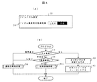
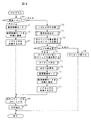
図6(A)は、異常発生時に正常なノズルのみでの印字制御を行うか否かを選択可能にするための画面例55である。図6(B)は、そのノズル制御フローチャートを示す。
異常発生時に正常なノズルのみでの印字制御を行う処理をノズル異常時の救済制御処理とすると、画面例55にて、項目56「ノズル異常時の救済制御」は、『しない/する』の選択肢を持ち、『する』のときのみ本実施例に基づく救済制御処理を行うこととする。 FIG. 6A shows an example of a screen 55 for making it possible to select whether or not to perform printing control using only normal nozzles when an abnormality occurs. FIG. 6B shows a nozzle control flowchart.
Assuming that the process of performing printing control with only normal nozzles when an abnormality occurs is the relief control process when the nozzle is abnormal, theitem 56 “Relief control when nozzle is abnormal” in the screen example 55 is an option of “do not / do” The relief control processing based on the present embodiment is performed only when “Yes” is held.
異常発生時に正常なノズルのみでの印字制御を行う処理をノズル異常時の救済制御処理とすると、画面例55にて、項目56「ノズル異常時の救済制御」は、『しない/する』の選択肢を持ち、『する』のときのみ本実施例に基づく救済制御処理を行うこととする。 FIG. 6A shows an example of a screen 55 for making it possible to select whether or not to perform printing control using only normal nozzles when an abnormality occurs. FIG. 6B shows a nozzle control flowchart.
Assuming that the process of performing printing control with only normal nozzles when an abnormality occurs is the relief control process when the nozzle is abnormal, the
図6(B)に示す、フローチャートでは、まず、分岐57でノズル異常箇所を判定する。ノズル異常は、制御信号29を用いてノズル状態を監視することで判定する。2つのノズルが両方異常ありのとき、処理58にて通常の異常処理に移動する。通常の異常処理では、異常となったノズルの印字を中断し、ノズルが異常状態であることをディスプレイ18にメッセージ表示する。片方のノズルのみ異常ありのとき、処理59にて項目56「ノズル異常時の救済制御」の設定をチェックする。設定が『しない』のとき、処理58にて通常の異常処理に移動する。『する』のとき、救済制御処理f2を実行する。救済制御処理f2の詳細は後述する。異常なしのときには、処理60にて2つのノズルを制御する方式のままとし、処理61にてノズルα、ノズルβそれぞれの印字範囲である印字パラメータL(L1,L2)、M(M1,M2)を使用した印字を継続する。
In the flowchart shown in FIG. 6B, first, a nozzle abnormal portion is determined at a branch 57. Nozzle abnormality is determined by monitoring the nozzle state using the control signal 29. When both of the two nozzles are abnormal, the process moves to normal abnormality processing in processing 58. In normal abnormality processing, printing of the nozzle that has become abnormal is interrupted, and a message is displayed on the display 18 that the nozzle is in an abnormal state. When there is an abnormality in only one of the nozzles, the setting of the item 56 “rescue control when the nozzle is abnormal” is checked in processing 59. When the setting is “NO”, the process proceeds to a normal abnormality process in process 58. When “Yes”, the relief control process f2 is executed. Details of the relief control process f2 will be described later. When there is no abnormality, the method of controlling the two nozzles is left in the process 60, and the print parameters L (L1, L2) and M (M1, M2) which are the print ranges of the nozzles α and β in the process 61, respectively. Continue printing using.
本実施例によれば、ノズル異常時の救済制御処理を行うかどうかの設定を入力できるので、搬送ラインをすぐに止めても構わない場合や、試験モードでの設定時等の、自動的に救済制御処理を行う必要のないときには、救済制御処理をOFFに設定できる効果がある。
According to this embodiment, since it is possible to input a setting as to whether or not the relief control process is performed when the nozzle is abnormal, it is possible to automatically stop the conveyance line or automatically when setting in the test mode. When the relief control process does not need to be performed, the relief control process can be set to OFF.
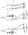
図7は、ツインノズルでノズルが縦方向配置の場合の、本実施例における、正常時の印字と異常時の印字でのインク粒子飛行例である。このうち、図7(A)にノズルαとノズルβの双方が正常に動作する場合の正常印字47についてインク粒子飛行例62を示し、図7(B)にノズルαが異常のときの印字50-αについてインク粒子飛行例63-αを示し、図7(C)にノズルβが異常のときの印字50-βについてインク粒子飛行例63-βを示す。ここで、インク粒子飛行例は、文字縦方向を示している。
FIG. 7 is an example of ink particle flight in normal printing and abnormal printing in this embodiment when the nozzles are arranged in the vertical direction with twin nozzles. Of these, FIG. 7A shows an ink particle flight example 62 for normal printing 47 when both nozzle α and nozzle β operate normally, and FIG. 7B shows printing 50 when nozzle α is abnormal. Ink particle flight example 63-α is shown for -α, and FIG. 7C shows ink particle flight example 63-β for print 50-β when nozzle β is abnormal. Here, the ink particle flight example shows the vertical direction of the character.
まず、正常印字47のときには、図7(A)に示すようにインク粒子飛行例62は印字内容に合わせて正常に飛行する。また、ノズルαが異常のときには、図7(B)に示すように、ノズルβのみで印字するため、インク粒子飛行例63-αのように正常印字47に比べてノズルβが印字する範囲が文字縦方向に広がるが、インク粒子24の着弾位置は正常印字47のインク粒子飛行例62と同じ場所となる。
First, at the time of normal printing 47, as shown in FIG. 7A, the ink particle flight example 62 normally flies in accordance with the printing contents. Further, when the nozzle α is abnormal, as shown in FIG. 7B, printing is performed only with the nozzle β, so the range in which the nozzle β prints compared to the normal printing 47 as in the ink particle flight example 63-α. Although spread in the vertical direction of the character, the landing position of the ink particles 24 is the same place as the ink particle flight example 62 of the normal print 47.
同様に、ノズルβが異常のときには、図7(C)に示すように、ノズルαのみで印字するため、インク粒子飛行例63-βのように正常印字47に比べてノズルαが印字する範囲が文字縦方向に広がる。しかし、インク粒子24の偏向方向は常に上方に偏向するため、インク粒子24の着弾位置は正常印字47のインク粒子飛行例62と異なり、文字縦方向の上方に移動してしまうという問題がある。
Similarly, when the nozzle β is abnormal, as shown in FIG. 7C, printing is performed only with the nozzle α, so the range in which the nozzle α prints compared to the normal printing 47 as in the ink particle flying example 63-β. Expands vertically. However, since the deflection direction of the ink particles 24 is always deflected upward, the landing position of the ink particles 24 is different from the ink particle flight example 62 of the normal printing 47, and there is a problem that it moves upward in the character vertical direction.
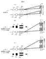
図8は、ツインノズルでノズルが横方向配置の場合の、本実施例における、正常時の印字と異常時の印字でのインク粒子飛行例である。このうち、図8(A)にノズルαとノズルβの双方が正常に動作する場合の正常印字51についてインク粒子飛行例64を示し、図8(B)にノズルαが異常のときの印字54-αについてインク粒子飛行例65-αを示し、図8(C)にノズルβが異常のときの印字54-βについてインク粒子飛行例65-βを示す。ここで、インク粒子飛行例は、図7とは異なり、搬送ライン方向を示している。
FIG. 8 is an example of ink particle flight in normal printing and abnormal printing in this embodiment when the nozzles are arranged in a horizontal direction with twin nozzles. Of these, FIG. 8A shows an ink particle flight example 64 for normal printing 51 when both nozzle α and nozzle β operate normally, and FIG. 8B shows printing 54 when nozzle α is abnormal. The ink particle flight example 65-α is shown for -α, and FIG. 8C shows the ink particle flight example 65-β for the print 54-β when the nozzle β is abnormal. Here, unlike the example of FIG. 7, the ink particle flight example shows the direction of the transport line.
まず、正常印字51のときには、図8(A)に示すようにインク粒子飛行例64は印字内容に合わせて正常に飛行する。また、ノズルαが異常のときには、図8(B)に示すように、ノズルβのみで印字するため、インク粒子飛行例65-αのように正常印字51に比べてノズルβが印字する範囲が搬送ライン方向に広がるが、インク粒子の着弾位置は正常印字51のインク粒子飛行例64と同じ場所となる。
First, in the case of normal printing 51, as shown in FIG. 8A, the ink particle flight example 64 normally flies in accordance with the printing content. Further, when the nozzle α is abnormal, as shown in FIG. 8B, printing is performed only with the nozzle β, so the range in which the nozzle β prints compared to the normal printing 51 as in the ink particle flying example 65-α. Although spreading in the transport line direction, the landing position of the ink particles is the same place as the ink particle flight example 64 of the normal print 51.
同様に、ノズルβが異常のときには、図8(C)に示すように、ノズルαのみで印字するため、インク粒子飛行例65-βのように正常印字51に比べてノズルαが印字する範囲は搬送ライン方向に広がる。また、ノズルαとノズルβの配置上、正常なノズルが印字する文字縦方向の範囲は変化しないため、インク粒子の着弾位置は正常印字51のインク粒子飛行例64と同じ場所となる。
Similarly, when the nozzle β is abnormal, as shown in FIG. 8C, printing is performed only with the nozzle α, so the range in which the nozzle α is printed compared to the normal printing 51 as in the ink particle flying example 65-β. Spreads in the direction of the transport line. In addition, because the arrangement of the nozzles α and β does not change the vertical range of characters printed by normal nozzles, the ink particle landing position is the same location as the ink particle flight example 64 of the normal print 51.
このように、異常発生時に正常なノズルのみで印字制御を行う際、正常なノズルの位置に応じて印字位置が移動してしまう場合があり、印字制御を変更する必要がある。これを解決するための、救済制御処理f2を以下説明する。
As described above, when printing control is performed using only normal nozzles when an abnormality occurs, the printing position may move depending on the position of the normal nozzles, and it is necessary to change the printing control. The relief control process f2 for solving this will be described below.
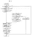
図9は、本実施例での図6(B)に示すノズル制御フローチャート実行時に、図6(A)に示す項目56「ノズル異常時の救済制御」が『する』のときに実行する、救済制御処理のフローチャートf2である。図9において、まず、分岐66にて異常発生ノズルがノズルα、ノズルβのどちらなのかをチェックする。
FIG. 9 shows the relief executed when the item 56 “Relief Control at Nozzle Abnormality” shown in FIG. 6A is “Yes” when the nozzle control flowchart shown in FIG. It is a flowchart f2 of a control process. In FIG. 9, first, at branch 66, it is checked whether the abnormal nozzle is nozzle α or nozzle β.
ノズルαが異常のとき、処理r1にてインクジェット記録装置が救済制御を実施する『救済制御モード』であることを設定するとともに、処理r2にて救済制御モードであることを外部に通知する。このとき、通知する手段はディスプレイ18での画面表示や接続装置33での通信・信号とする。その後、処理67にてノズルβのみ制御する方式とし、処理68にて印字パラメータNを使用した印字を行い、処理69にて印字続行する。
When the nozzle α is abnormal, it is set in the “relief control mode” in which the inkjet recording apparatus performs the relief control in the process r1, and the outside is notified in the process r2 that it is in the relief control mode. At this time, the notification means is a screen display on the display 18 or a communication / signal on the connection device 33. Thereafter, in a process 67, only the nozzle β is controlled, printing is performed using the print parameter N in a process 68, and printing is continued in a process 69.
ノズルβが異常のとき、処理70にてノズルβの印字を中断し、処理71にてノズルβが異常状態であることをディスプレイ18にメッセージ表示する。その後、処理72にて印字ヘッド位置変更を促すガイダンスを表示する。このガイダンスは、印字ヘッド位置変更有無を顧客に選択させるための表示である。これは、図7で説明したように、印字位置が移動してしまう場合の対策であり、分岐73にて印字ヘッド位置を変更する場合は、異常発生時に正常なノズルのみで印字制御を行う救済制御が可能となる。処理74では印字ヘッド位置を物理的に移動して、処理75でガイダンスを消去し、処理76にて印字可能状態に遷移する。その後、上述した、処理r1、r2の処理を行った後、処理77にてノズルαのみ制御する方式とし、処理68にて印字パラメータNを使用した印字を行い、処理69にて印字続行する。
When the nozzle β is abnormal, the printing of the nozzle β is interrupted in a process 70, and a message is displayed on the display 18 that the nozzle β is in an abnormal state in a process 71. Thereafter, in a process 72, guidance for prompting the change of the print head position is displayed. This guidance is a display for allowing the customer to select whether or not to change the print head position. As described with reference to FIG. 7, this is a countermeasure for a case where the print position moves. When the print head position is changed at branch 73, a relief is performed in which print control is performed using only normal nozzles when an abnormality occurs. Control becomes possible. In process 74, the print head position is physically moved, the guidance is deleted in process 75, and the process shifts to a printable state in process 76. Thereafter, after the processes r1 and r2 described above are performed, only the nozzle α is controlled in process 77, printing using the print parameter N is performed in process 68, and printing is continued in process 69.
分岐73にて印字ヘッド位置を変更しない場合は、異常発生時に正常なノズルのみで印字制御を行う救済制御ができない。そのため、処理78でガイダンス表示を最小化し処理を終了する。このとき、ノズル異常にも関わらず『救済制御モード』を実行せず、通常の印字制御のまま動作する。この状態で『救済制御モード』としたい場合は、ガイダンス表示を再度最大化してから処理73で印字ヘッド位置を変更することで、『救済制御モード』に変更できる。
If the print head position is not changed at branch 73, the relief control for performing the print control with only normal nozzles when an abnormality occurs cannot be performed. Therefore, the guidance display is minimized in process 78 and the process is terminated. At this time, the “relief control mode” is not executed in spite of the nozzle abnormality, and the normal printing control is performed. If it is desired to set the “relief control mode” in this state, it is possible to change to the “relief control mode” by maximizing the guidance display again and then changing the print head position in step 73.
図10は、異常発生時に正常なノズルのみで印字制御を行う救済制御でノズル異常が解除されたときの、処理フローチャートである。分岐79にて異常解除されたか判定し、解除された場合、分岐80にて救済制御モードにて印字したかチェックする。救済制御モードであった場合、更に分岐81にて異常解除されたノズルをチェックする。
FIG. 10 is a processing flowchart when the nozzle abnormality is canceled by the relief control in which the printing control is performed only with the normal nozzle when the abnormality occurs. It is determined whether or not the abnormality has been canceled at branch 79, and if it is canceled, it is checked at branch 80 whether printing has been performed in the repair control mode. If it is in the relief control mode, the nozzle that has been abnormally released is checked at branch 81.
ノズルαが異常解除された場合、処理n1にて救済制御モードを解除するとともに、処理n2にて救済制御モード解除を外部に通知する。このとき、通知する手段はディスプレイ18での画面表示や接続装置33での通信・信号とする。その後、処理82にて2つのノズルを制御する方式とし、処理83にてノズルα、ノズルβそれぞれの印字範囲である印字パラメータL(L1,L2)、M(M1,M2)を使用した印字を行い、処理84にて印字続行する。
When the nozzle α is released abnormally, the relief control mode is released in the process n1, and the release of the relief control mode is notified to the outside in the process n2. At this time, the notification means is a screen display on the display 18 or a communication / signal on the connection device 33. Thereafter, in a process 82, two nozzles are controlled, and in a process 83, printing using the print parameters L (L1, L2) and M (M1, M2), which are the print ranges of the nozzles α and β, respectively. In step 84, printing is continued.
ノズルβが異常解除された場合、処理85にて印字ヘッド位置変更を促すガイダンスを表示する。このガイダンスは、印字ヘッド位置変更有無を顧客に選択させるための表示である。分岐86にて印字ヘッド位置を変更する場合は、通常の印字制御に戻ることができる。このとき、処理87にて印字ヘッド位置を変更し、処理88でガイダンス消去する。その後、上述した、処理n1、n2の処理へ移行する。
When the nozzle β is released abnormally, a guidance for prompting a change of the print head position is displayed in processing 85. This guidance is a display for allowing the customer to select whether or not to change the print head position. When the print head position is changed at the branch 86, the normal print control can be returned. At this time, the print head position is changed in process 87, and the guidance is erased in process 88. Thereafter, the process proceeds to the processes n1 and n2.
分岐86にて印字ヘッド位置を変更しない場合は、通常の印字制御に戻ることができない。このとき、処理89でガイダンス表示を最小化し処理を終了する。この場合、ノズル異常が解除されても通常の印字制御ではなく『救済制御モード』のまま動作する。この状態で通常の印字制御としたい場合は、ガイダンス表示を再度最大化してから分岐86で印字ヘッド位置を変更することで、通常の印字制御に変更できる。
If the print head position is not changed at branch 86, it is not possible to return to normal print control. At this time, the guidance display is minimized in process 89 and the process is terminated. In this case, even if the nozzle abnormality is canceled, the operation is performed in the “relief control mode” instead of the normal print control. If normal print control is desired in this state, the guidance display can be maximized again and then the print head position can be changed at branch 86 to change to normal print control.
以上のように、本実施例では、異常発生時に正常なノズルのみで印字制御を行う際、正常なノズルの位置に応じて印字位置が移動してしまう場合でも対応が可能であり、異常が発生しても正常時と同じ印字結果を得ることができ、印字の無駄を低減することができる。
As described above, in this embodiment, when printing control is performed with only normal nozzles when an abnormality occurs, it is possible to cope with the case where the printing position moves according to the position of the normal nozzle, and an abnormality occurs. Even in this case, the same printing result as that in the normal state can be obtained, and printing waste can be reduced.
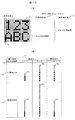
図11(A)は、本実施例での、ノズルα、βがともに正常時の正常時印字47とノズルαが異常時の異常時印字50でのノズルβの印字範囲を示している。また、図11(B)は、図11(A)の印字範囲のうちの縦1ライン90を印字する際に必要なノズルβから飛行するインク粒子数を示す表である。
FIG. 11A shows the printing range of the nozzle β in the normal printing 47 when the nozzles α and β are both normal and the abnormal printing 50 when the nozzle α is abnormal in the present embodiment. FIG. 11B is a table showing the number of ink particles flying from the nozzle β necessary for printing one vertical line 90 in the printing range of FIG.
縦1ライン90を印字する際のインク飛行数は、印字パラメータ内のインク粒子使用率45の値により変化する。ここで、インク粒子使用率45とは、ノズルから出力されたインク粒子のうち実際に印字に用いるインク粒子を間引きする割合を指定するパラメータであり、印字を実行するインク粒子使用数をノズルから出力されるインク粒子のN個のうちの1個としたい場合、1/N個と指定して使用する。例えば、2個のうち1個を使用する場合は1/2となる。インク粒子使用率45は、印字品質や搬送ライン速度に合わせて最適な値が異なる。一般的に、間引きの割合を大きくすれば、インクとインク間の影響を抑えることができるので、より印字品質を良くすることが可能である一方、搬送ライン速度の高速化には対応困難となる。
The number of ink flights when printing one vertical line 90 varies depending on the value of the ink particle usage rate 45 in the printing parameters. Here, the ink particle usage rate 45 is a parameter for designating a ratio of thinning out ink particles actually used for printing out of the ink particles output from the nozzle, and the number of ink particles used for printing is output from the nozzle. When it is desired to set one of N ink particles to be used, 1 / N is designated and used. For example, when one of the two is used, it becomes 1/2. The ink particle usage rate 45 varies depending on the print quality and the conveyance line speed. In general, increasing the thinning ratio can suppress the influence between inks, so that it is possible to improve the printing quality, but it is difficult to cope with an increase in the conveyance line speed. .
ここで、図11(B)の表91において、インク粒子使用率45が同一のときの正常時印字47および異常時印字50での印字に用いるインク粒子数を説明する。インク粒子使用率45が1/1のとき、正常時印字47での印字に用いるインク粒子数92は8個、異常時印字50での印字に用いるインク粒子数93は16個となる。同様に、インク粒子使用率45が1/2のとき、正常時印字47での印字に用いるインク粒子数94は16個、異常時印字50での印字に用いるインク粒子数95は32個となる。インク粒子は等速でノズルから出力されるため、印字に用いるインク粒子数は縦1ライン90の印字に必要な時間に等しい。つまり、搬送ライン速度およびインク粒子使用率45に変化がないとき、救済制御モードで異常時印字50を印字すると、印字に使用するインク粒子数および印字にかかる時間は正常時印字47の2倍分が必要となる。そのため、救済制御モードで異常時印字50を印字するときに正常時印字47と同様の印字結果を得るためには、パラメータ補正の他にも補正処理を行う必要がある。
Here, in Table 91 in FIG. 11B, the number of ink particles used for printing in the normal printing 47 and the abnormal printing 50 when the ink particle usage rate 45 is the same will be described. When the ink particle usage rate 45 is 1/1, the number 92 of ink particles used for printing in the normal time printing 47 is 8, and the number 93 of ink particles used for printing in the abnormal time printing 50 is 16. Similarly, when the ink particle usage rate 45 is 1/2, the number 94 of ink particles used for printing in the normal printing 47 is 16, and the number 95 of ink particles used for printing in the abnormal printing 50 is 32. . Since the ink particles are output from the nozzles at a constant speed, the number of ink particles used for printing is equal to the time required for printing one vertical line 90. In other words, when there is no change in the transport line speed and the ink particle usage rate 45, when the abnormal print 50 is printed in the relief control mode, the number of ink particles used for printing and the time required for printing are twice the normal print 47. Is required. For this reason, in order to obtain a printing result similar to the normal printing 47 when printing the abnormal printing 50 in the relief control mode, it is necessary to perform a correction process in addition to the parameter correction.
補正処理の方法としては2種類ある。一つは、異常時印字50のとき、搬送ライン速度も遅くする方法である。この補正処理は、印字パラメータを内部で変更することなく印字できるという利点がある。この場合、救済制御モードかどうかを外部に通知する必要があり、これは図9のフローチャートf2の処理r2または図10のフローチャートの処理n2で実現できる。
There are two types of correction processing methods. One is a method in which the conveyance line speed is also slowed at the time of abnormal printing 50. This correction process has an advantage that printing can be performed without changing the printing parameters internally. In this case, it is necessary to notify the outside whether or not it is in the relief control mode, and this can be realized by the process r2 in the flowchart f2 in FIG. 9 or the process n2 in the flowchart in FIG.
他の一つは、あらかじめ、設定できるインク粒子使用率45を制限しておき、異常時印字50のときは、インク粒子使用率45を補正して印字を行う方法である。具体的には、ノズルα、ノズルβのインク粒子使用率45を1/Nとしたとき、あらかじめ、Nを偶数値で同じ値として設定しておく。この状態で正常時印字47を行う場合、ノズルα、βはそれぞれ設定したインク粒子使用率45で印字する。また、救済制御モードで異常時印字50を行う場合、正常なノズルが印字に使用するインク粒子数は2倍となるので、設定したインク粒子使用率45の2倍の値(すなわち、Nを半分とする)を新たなインク粒子使用率45に自動補正して印字を行う。あらかじめ設定しておくNを偶数値とする理由は、救済制御モードで半分にする必要があるため割り切れる値としたほうが扱いやすいこと、また、同じ値とする理由は、それぞれのノズル印字制御を簡単にするためである。
The other is a method in which the ink particle usage rate 45 that can be set is limited in advance, and when printing 50 is performed in an abnormal state, the ink particle usage rate 45 is corrected to perform printing. Specifically, when the ink particle usage rate 45 of the nozzles α and β is set to 1 / N, N is set in advance as an equal value with an even value. When normal printing 47 is performed in this state, the nozzles α and β print with the ink particle usage rate 45 set. In addition, when the abnormal printing 50 is performed in the relief control mode, the number of ink particles used for printing by a normal nozzle is doubled. Therefore, a value twice the set ink particle usage rate 45 (that is, N is halved). Is automatically corrected to a new ink particle usage rate 45 and printing is performed. The reason why N is set in advance as an even value is that it is easier to handle a divisible value because it must be halved in the relief control mode, and the reason for setting the same value is that each nozzle print control is easy. It is to make it.
図11(B)の表91の例を挙げると、補正ありの欄に記載しているように、正常時印字47の場合は、ノズルα、βのインク粒子使用率を、1/1は使わず、1/2として設定、このときのインク粒子数96は16個となる。その後、救済制御モードで異常時印字50となった場合は、インク粒子使用率を、使用する粒子の数が倍になるので、インク粒子使用率を設定した値の2倍として、1/1に補正し、このときのインク粒子数97も16個となる。この補正処理は、搬送ライン速度を変更する必要が無いという利点がある。
In the example of Table 91 in FIG. 11B, as described in the column with correction, in the case of normal printing 47, the ink particle usage rate of the nozzles α and β is 1/1. First, it is set as 1/2, and the number of ink particles 96 at this time is 16. After that, when the abnormal printing 50 is obtained in the relief control mode, the ink particle usage rate is doubled, so the ink particle usage rate is doubled to a value set to 1/1. Correction is made, and the number of ink particles 97 at this time is also 16. This correction process has the advantage that it is not necessary to change the transport line speed.
以上のように、本実施例では、ノズル異常時の救済制御を行う際に、あらかじめ定められたインク粒子使用率の補正を行うことにより、正常時印字と異常時印字での印字品質を同一とすることができるという効果がある。
As described above, in this embodiment, when performing relief control in the event of nozzle abnormality, the print quality in normal printing and abnormal printing is made the same by correcting a predetermined ink particle usage rate. There is an effect that can be done.
前述の実施例においては、ノズルが2つの場合について説明したが、ノズルが3つ以上存在する場合を考える。この場合、ツインノズルでの制御方法を合成したものであるので、前述した本実施例を、3つ以上のノズルのうちの任意の2つのノズルに対して使用することで、同様に問題を解決できる。
In the above-described embodiment, the case where there are two nozzles has been described, but a case where there are three or more nozzles will be considered. In this case, since the control method using twin nozzles is synthesized, the problem can be solved in the same manner by using the above-described embodiment for any two of the three or more nozzles. it can.
なお、図7(C)に示したように、ノズルが縦配置の場合、異常ノズルの印字すべき内容を、その上側に配置されている正常なノズルで印字しようとすると、文字縦方向の上方に印字が移動してしまうという問題があるので、異常ノズルの下側に正常ノズルがある場合には、下側に配置されている正常ノズルでサポートするのが望ましい。
As shown in FIG. 7C, when the nozzles are arranged vertically, if the contents to be printed by the abnormal nozzles are to be printed by the normal nozzles arranged on the upper side, the upper side in the character longitudinal direction is displayed. Therefore, if there is a normal nozzle below the abnormal nozzle, it is desirable to support it with the normal nozzle arranged on the lower side.
また、異常ノズルに隣接する正常ノズルで異常ノズルの印字すべき内容を印字するようにすることで、正常ノズルの印字範囲を必要最小限とすることができる。
本発明は上記した実施例に限定されるものではなく、様々な変形例が含まれる。例えば、上記した実施例は本発明を分かりやすく説明するために詳細に説明したものであり、例えば、上記した実施例では、ツインノズルの配置が、縦の場合と横の場合について説明したが、この配置に限定されるものでなく、例えば、ノズルαとノズルβの配置を斜め方向に配置することも考えられる。この場合、斜め方向は、縦方向と横方向の配置を合成したものと考えられるので、前述した本実施例のうち縦方向と横方向の制御を同時、もしくは組合せて使用することで、同様に問題を解決できる。
また、必ずしも説明した全ての構成を備えるものに限定されるものではない。また、ある実施例の構成の一部を他の実施例の構成に置き換えることが可能であり、ある実施例の構成に他の実施例の構成を加えることも可能である。また、各実施例の構成の一部について、他の構成の追加、削除、置換をすることも可能である。 In addition, by printing the content to be printed by the abnormal nozzle with the normal nozzle adjacent to the abnormal nozzle, the print range of the normal nozzle can be minimized.
The present invention is not limited to the above-described embodiments, and includes various modifications. For example, the above-described embodiment has been described in detail for easy understanding of the present invention.For example, in the above-described embodiment, the arrangement of the twin nozzles has been described for the vertical and horizontal cases. For example, it is conceivable to arrange the nozzles α and β in an oblique direction. In this case, since the diagonal direction is considered to be a combination of the vertical and horizontal arrangements, by using the vertical and horizontal controls simultaneously or in combination in the above-described embodiment, the same applies. Can solve the problem.
Moreover, it is not necessarily limited to what has all the structures demonstrated. Further, a part of the configuration of one embodiment can be replaced with the configuration of another embodiment, and the configuration of another embodiment can be added to the configuration of one embodiment. Moreover, it is also possible to add, delete, and replace other configurations for a part of the configuration of each embodiment.
1 :インクジェット記録装置
21 :印字ヘッド
22a:ツインノズルでのノズルα
22b:ツインノズルでのノズルβ
37 :印字範囲(パラメータN1)
41 :印字範囲(パラメータN2)
42 :印字パラメータ
56 :項目「ノズル異常時の救済制御」
f2:救済制御フローチャート 1: Inkjet recording apparatus 21:Print head 22a: Nozzle α with twin nozzles
22b: Nozzle β with twin nozzle
37: Print range (parameter N1)
41: Print range (parameter N2)
42: Print parameter 56: Item “Relief control when nozzle is abnormal”
f2: Relief control flowchart
21 :印字ヘッド
22a:ツインノズルでのノズルα
22b:ツインノズルでのノズルβ
37 :印字範囲(パラメータN1)
41 :印字範囲(パラメータN2)
42 :印字パラメータ
56 :項目「ノズル異常時の救済制御」
f2:救済制御フローチャート 1: Inkjet recording apparatus 21:
22b: Nozzle β with twin nozzle
37: Print range (parameter N1)
41: Print range (parameter N2)
42: Print parameter 56: Item “Relief control when nozzle is abnormal”
f2: Relief control flowchart
Claims (7)
- インクを噴出して粒子化するノズルと、インク粒子に帯電電圧を掛けて帯電させる帯電電極と、帯電したインク粒子を偏向させる偏向電極と、印字に使用しないインク粒子を回収するガターからなるサブ印字ヘッドを複数有するインクジェット記録装置において、
サブ印字ヘッドが異常となったかどうかを検知する検知部と、
前記複数のサブ印字ヘッドをそれぞれ独立に制御して印字制御を行う制御部を有し、
該制御部は、前記検知部で1つのサブ印字ヘッドが異常と検知したとき、該異常サブ印字ヘッドが印字すべき印字内容を他の正常なサブ印字ヘッドで印字するように印字制御を切り替えることを特徴とするインクジェット記録装置。 Sub-printing consisting of a nozzle that ejects ink into particles, a charging electrode that charges ink particles by applying a charging voltage, a deflection electrode that deflects charged ink particles, and a gutter that collects ink particles that are not used for printing In an inkjet recording apparatus having a plurality of heads,
A detection unit for detecting whether or not the sub print head is abnormal;
A control unit for controlling printing by independently controlling the plurality of sub print heads;
When the control unit detects that one sub print head is abnormal, the control unit switches the print control so that the print content to be printed by the abnormal sub print head is printed by another normal sub print head. An ink jet recording apparatus. - 請求項1に記載のインクジェット記録装置であって、
前記ノズルごとの制御パラメータを保存する記憶部を有し、
該記憶部には、1つの印字結果を複数のサブ印字ヘッドで印字する場合と、1つの印字結果を異常発生したサブ印字ヘッド以外のサブ印字ヘッドで印字する場合のそれぞれの制御パラメータを保存しており、
前記制御部は、ノズルの状態に応じて前記制御パラメータのいずれかを使用して印字制御を行うことを特徴とするインクジェット記録装置。 The inkjet recording apparatus according to claim 1,
A storage unit for storing control parameters for each nozzle;
The storage unit stores control parameters for printing one print result with a plurality of sub print heads and for printing one print result with a sub print head other than the sub print head in which an abnormality has occurred. And
The ink jet recording apparatus, wherein the control unit performs print control using any of the control parameters according to a state of a nozzle. - 請求項1または2のいずれか1項に記載のインクジェット記録装置であって、
前記異常サブ印字ヘッドが印字すべき印字内容を他の正常なサブ印字ヘッドで印字する救済制御を行うかどうかの設定を入力できる入力部を有し、該入力結果が救済制御を行う設定の場合に、前記検知手段で1つのサブ印字ヘッドが異常と検知したとき、該異常サブ印字ヘッドの使用を中止して、前記救済制御に切り替えることを特徴とするインクジェット記録装置。 The inkjet recording apparatus according to any one of claims 1 and 2,
In the case where the abnormal sub print head has an input unit that can input a setting for whether or not to perform relief control for printing the content to be printed by another normal sub print head, and the input result is a setting for performing relief control In addition, when one of the sub print heads is detected to be abnormal by the detecting means, the use of the abnormal sub print head is stopped and the ink jet recording apparatus is switched to the relief control. - 請求項1~3のいずれか1項に記載のインクジェット記録装置であって、前記異常サブ印字ヘッドが印字すべき印字内容を他の正常なサブ印字ヘッドで印字する印字制御に切り替えたときにその状態を保存する記録部と、該状態を装置外部に出力する出力部とを有することを特徴とするインクジェット記録装置。 The inkjet recording apparatus according to any one of claims 1 to 3, wherein when the print content to be printed by the abnormal sub print head is switched to print control for printing by another normal sub print head, An ink jet recording apparatus comprising: a recording unit that stores a state; and an output unit that outputs the state to the outside of the apparatus.
- 請求項1~4のいずれか1項に記載のインクジェット記録装置であって、
前記複数のサブ印字ヘッドは縦に配置されており、
前記他の正常なサブ印字ヘッドが前記異常サブ印字ヘッドの上側に配置されている場合には、前記異常サブ印字ヘッドが印字すべき印字内容を他の正常なサブ印字ヘッドで印字するように印字制御を切り替える前に、
当該正常サブ印字ヘッドの位置を縦方向に移動させることを特徴とするインクジェット記録装置。 The inkjet recording apparatus according to any one of claims 1 to 4,
The plurality of sub print heads are arranged vertically,
When the other normal sub print head is disposed above the abnormal sub print head, the print contents to be printed by the abnormal sub print head are printed by the other normal sub print head. Before switching control,
An inkjet recording apparatus, wherein the position of the normal sub print head is moved in the vertical direction. - インクを噴出して粒子化するノズルと、インク粒子に帯電電圧を掛けて帯電させる帯電電極と、帯電したインク粒子を偏向させる偏向電極と、印字に使用しないインク粒子を回収するガターからなるサブ印字ヘッドを複数有するインクジェット記録装置において、
サブ印字ヘッドが異常となったかどうかを検知する検知部と、
前記複数のサブ印字ヘッドをそれぞれ独立に制御して印字制御を行う制御部を有し、
該制御部は、前記検知部で1つのサブ印字ヘッドが異常と検知したとき、該異常サブ印字ヘッドの使用を中止して、該異常サブ印字ヘッドが印字すべき印字内容を他の正常なサブ印字ヘッドで印字する救済制御を行うように印字制御を切り替え、あらかじめ定められた、ノズルから出たインク粒子のうち印字に用いるインク粒子を間引く割合であるインク粒子使用率の補正を行う、ことを特徴とするインクジェット記録装置。 Sub-printing consisting of a nozzle that ejects ink into particles, a charging electrode that charges ink particles by applying a charging voltage, a deflection electrode that deflects charged ink particles, and a gutter that collects ink particles that are not used for printing In an inkjet recording apparatus having a plurality of heads,
A detection unit for detecting whether or not the sub print head is abnormal;
A control unit for controlling printing by independently controlling the plurality of sub print heads;
When the detection unit detects that one of the sub print heads is abnormal, the control unit stops using the abnormal sub print head and changes the print contents to be printed by the abnormal sub print head to another normal sub print head. The print control is switched so as to perform the relief control for printing with the print head, and the ink particle usage rate, which is a predetermined ratio of thinning out the ink particles used for printing out of the ink particles emitted from the nozzles, is corrected. An ink jet recording apparatus. - 請求項1~6のいずれか1項に記載のインクジェット記録装置であって、
前記検知部は、前記サブ印字ヘッドの状態を監視するセンサであって、サブ印字ヘッド内のノズル、帯電電極、偏向電極の状態を監視することによって異常を検知することを特徴とするインクジェット記録装置。 The ink jet recording apparatus according to any one of claims 1 to 6,
The detection unit is a sensor that monitors a state of the sub print head, and detects an abnormality by monitoring a state of a nozzle, a charging electrode, and a deflection electrode in the sub print head. .
Priority Applications (1)
| Application Number | Priority Date | Filing Date | Title |
|---|---|---|---|
| CN201480034834.2A CN105339174B (en) | 2013-07-03 | 2014-06-10 | Ink-jet recording apparatus |
Applications Claiming Priority (2)
| Application Number | Priority Date | Filing Date | Title |
|---|---|---|---|
| JP2013139817A JP6114125B2 (en) | 2013-07-03 | 2013-07-03 | Inkjet recording device |
| JP2013-139817 | 2013-07-03 |
Publications (1)
| Publication Number | Publication Date |
|---|---|
| WO2015001919A1 true WO2015001919A1 (en) | 2015-01-08 |
Family
ID=52143503
Family Applications (1)
| Application Number | Title | Priority Date | Filing Date |
|---|---|---|---|
| PCT/JP2014/065283 WO2015001919A1 (en) | 2013-07-03 | 2014-06-10 | Inkjet recording device |
Country Status (3)
| Country | Link |
|---|---|
| JP (1) | JP6114125B2 (en) |
| CN (1) | CN105339174B (en) |
| WO (1) | WO2015001919A1 (en) |
Cited By (1)
| Publication number | Priority date | Publication date | Assignee | Title |
|---|---|---|---|---|
| CN105584218A (en) * | 2016-02-01 | 2016-05-18 | 厦门英杰华机电科技有限公司 | CIJ code spraying system with double parallel nozzles |
Families Citing this family (6)
| Publication number | Priority date | Publication date | Assignee | Title |
|---|---|---|---|---|
| JP6338861B2 (en) | 2014-01-08 | 2018-06-06 | 株式会社日立産機システム | Inkjet recording device |
| US20200189270A1 (en) * | 2016-08-22 | 2020-06-18 | Hitachi Industrial Equipment Systems Co., Ltd. | Inkjet Recording Device and Inkjet Recording Device Control Method |
| CN110325367B (en) * | 2017-04-05 | 2021-03-16 | 株式会社日立产机系统 | Ink jet recording apparatus |
| JP7112257B2 (en) * | 2018-06-11 | 2022-08-03 | 株式会社日立産機システム | Inkjet recording device management system and inkjet recording device |
| JP7124524B2 (en) | 2018-07-31 | 2022-08-24 | 住友ゴム工業株式会社 | Golf ball |
| CN111000357B (en) * | 2018-10-04 | 2023-01-03 | 卡西欧计算机株式会社 | Nail print apparatus, nail print method, and recording medium |
Citations (2)
| Publication number | Priority date | Publication date | Assignee | Title |
|---|---|---|---|---|
| JPH08238760A (en) * | 1995-03-03 | 1996-09-17 | Hitachi Ltd | Ink jet recorder |
| JP2009018453A (en) * | 2007-07-10 | 2009-01-29 | Seiko Epson Corp | Liquid discharge apparatus, control method of liquid discharge apparatus and control program of liquid discharge apparatus |
Family Cites Families (5)
| Publication number | Priority date | Publication date | Assignee | Title |
|---|---|---|---|---|
| JP4629465B2 (en) * | 2005-03-11 | 2011-02-09 | 株式会社日立産機システム | Inkjet recording device |
| JP5364360B2 (en) * | 2008-12-15 | 2013-12-11 | 株式会社日立産機システム | Inkjet recording device |
| CN102282022B (en) * | 2009-06-24 | 2014-07-30 | 株式会社日立产机系统 | Ink jet recording device |
| JP5475578B2 (en) * | 2010-07-12 | 2014-04-16 | 株式会社日立産機システム | Ink jet recording apparatus and control method thereof |
| JP5759830B2 (en) * | 2011-08-19 | 2015-08-05 | 株式会社日立産機システム | Inkjet recording device |
-
2013
- 2013-07-03 JP JP2013139817A patent/JP6114125B2/en active Active
-
2014
- 2014-06-10 CN CN201480034834.2A patent/CN105339174B/en active Active
- 2014-06-10 WO PCT/JP2014/065283 patent/WO2015001919A1/en active Application Filing
Patent Citations (2)
| Publication number | Priority date | Publication date | Assignee | Title |
|---|---|---|---|---|
| JPH08238760A (en) * | 1995-03-03 | 1996-09-17 | Hitachi Ltd | Ink jet recorder |
| JP2009018453A (en) * | 2007-07-10 | 2009-01-29 | Seiko Epson Corp | Liquid discharge apparatus, control method of liquid discharge apparatus and control program of liquid discharge apparatus |
Cited By (1)
| Publication number | Priority date | Publication date | Assignee | Title |
|---|---|---|---|---|
| CN105584218A (en) * | 2016-02-01 | 2016-05-18 | 厦门英杰华机电科技有限公司 | CIJ code spraying system with double parallel nozzles |
Also Published As
| Publication number | Publication date |
|---|---|
| CN105339174A (en) | 2016-02-17 |
| JP6114125B2 (en) | 2017-04-12 |
| JP2015013385A (en) | 2015-01-22 |
| CN105339174B (en) | 2017-11-24 |
Similar Documents
| Publication | Publication Date | Title |
|---|---|---|
| WO2015001919A1 (en) | Inkjet recording device | |
| EP2789468B1 (en) | Image recording apparatus, control method thereof, and program | |
| US20140313255A1 (en) | Image recording apparatus, control method thereof, and recording medium | |
| JP2017177423A (en) | Droplet discharge device, system for controlling droplet discharge device and method for maintaining droplet discharge device | |
| JP2007007960A (en) | Liquid delivering apparatus, computer program, and cleaning method for nozzle | |
| JP5743802B2 (en) | Inkjet recording device | |
| JP2015013385A5 (en) | ||
| US9636911B2 (en) | Inkjet recording device | |
| JP2011255594A (en) | Liquid ejection device and liquid ejection method | |
| CN110826838B (en) | Method for providing digital production task by computer for multiple graphic industrial machine combined structure | |
| JP2012000790A (en) | Liquid ejection apparatus, and liquid ejection method | |
| JP3970905B2 (en) | Ink discharge apparatus and ink discharge control method | |
| JP5911735B2 (en) | Inkjet recording apparatus and method and method for manufacturing sanitary goods | |
| EP3045316B1 (en) | Recording apparatus and recording method | |
| JP2013184447A (en) | Inkjet recording device, inkjet recording method, and method for manufacturing sanitary article | |
| WO2015186499A1 (en) | Image-forming apparatus and image-forming method | |
| JP2016002650A (en) | Image forming device, method and program | |
| US20150258804A1 (en) | Printing control apparatus and printing control method | |
| JP2021084392A (en) | Liquid discharge device, and discharge control method of the liquid discharge device | |
| WO2022097491A1 (en) | Printing device and printing method | |
| JP4200582B2 (en) | Inkjet printer | |
| JP2015033821A (en) | Inkjet recording device | |
| JP2014188784A (en) | Printing method for printer and printer | |
| JP5736757B2 (en) | Printing apparatus and printing method | |
| US20210197564A1 (en) | Printing method and printing apparatus |
Legal Events
| Date | Code | Title | Description |
|---|---|---|---|
| WWE | Wipo information: entry into national phase |
Ref document number: 201480034834.2 Country of ref document: CN |
|
| 121 | Ep: the epo has been informed by wipo that ep was designated in this application |
Ref document number: 14820391 Country of ref document: EP Kind code of ref document: A1 |
|
| NENP | Non-entry into the national phase |
Ref country code: DE |
|
| 122 | Ep: pct application non-entry in european phase |
Ref document number: 14820391 Country of ref document: EP Kind code of ref document: A1 |