WO2014208739A1 - Fuel cell and method for manufacturing same - Google Patents
Fuel cell and method for manufacturing same Download PDFInfo
- Publication number
- WO2014208739A1 WO2014208739A1 PCT/JP2014/067219 JP2014067219W WO2014208739A1 WO 2014208739 A1 WO2014208739 A1 WO 2014208739A1 JP 2014067219 W JP2014067219 W JP 2014067219W WO 2014208739 A1 WO2014208739 A1 WO 2014208739A1
- Authority
- WO
- WIPO (PCT)
- Prior art keywords
- fuel cell
- fuel
- glass
- manifold
- sealing material
- Prior art date
Links
- 239000000446 fuel Substances 0.000 title claims abstract description 281
- 238000000034 method Methods 0.000 title claims description 17
- 238000004519 manufacturing process Methods 0.000 title claims description 12
- 239000011521 glass Substances 0.000 claims abstract description 147
- 239000003566 sealing material Substances 0.000 claims abstract description 79
- 230000006835 compression Effects 0.000 claims abstract description 78
- 238000007906 compression Methods 0.000 claims abstract description 78
- 239000007800 oxidant agent Substances 0.000 claims abstract description 18
- 230000001590 oxidative effect Effects 0.000 claims abstract description 18
- 239000003792 electrolyte Substances 0.000 claims abstract description 9
- 239000000463 material Substances 0.000 claims description 113
- 239000007789 gas Substances 0.000 claims description 94
- 239000002737 fuel gas Substances 0.000 claims description 40
- 230000002093 peripheral effect Effects 0.000 claims description 11
- 238000003825 pressing Methods 0.000 claims description 10
- 239000000565 sealant Substances 0.000 claims description 10
- 238000010438 heat treatment Methods 0.000 claims description 5
- 238000001816 cooling Methods 0.000 claims description 3
- 210000004027 cell Anatomy 0.000 description 171
- 238000003780 insertion Methods 0.000 description 55
- 230000037431 insertion Effects 0.000 description 55
- 239000007787 solid Substances 0.000 description 31
- 238000007789 sealing Methods 0.000 description 10
- 238000010248 power generation Methods 0.000 description 9
- 229910052751 metal Inorganic materials 0.000 description 7
- 239000002184 metal Substances 0.000 description 7
- 210000005056 cell body Anatomy 0.000 description 6
- 239000000919 ceramic Substances 0.000 description 5
- 230000000694 effects Effects 0.000 description 5
- 239000010445 mica Substances 0.000 description 5
- 229910052618 mica group Inorganic materials 0.000 description 5
- 238000005336 cracking Methods 0.000 description 4
- 238000003475 lamination Methods 0.000 description 4
- 238000012805 post-processing Methods 0.000 description 4
- 238000004891 communication Methods 0.000 description 3
- 229910001220 stainless steel Inorganic materials 0.000 description 3
- 238000002425 crystallisation Methods 0.000 description 2
- 230000008025 crystallization Effects 0.000 description 2
- 238000007599 discharging Methods 0.000 description 2
- 238000010292 electrical insulation Methods 0.000 description 2
- 229910000510 noble metal Inorganic materials 0.000 description 2
- 230000002265 prevention Effects 0.000 description 2
- 239000007784 solid electrolyte Substances 0.000 description 2
- 238000003466 welding Methods 0.000 description 2
- BVKZGUZCCUSVTD-UHFFFAOYSA-L Carbonate Chemical compound [O-]C([O-])=O BVKZGUZCCUSVTD-UHFFFAOYSA-L 0.000 description 1
- UFHFLCQGNIYNRP-UHFFFAOYSA-N Hydrogen Chemical compound [H][H] UFHFLCQGNIYNRP-UHFFFAOYSA-N 0.000 description 1
- 230000015572 biosynthetic process Effects 0.000 description 1
- 230000000903 blocking effect Effects 0.000 description 1
- 239000011195 cermet Substances 0.000 description 1
- 238000006243 chemical reaction Methods 0.000 description 1
- 239000000470 constituent Substances 0.000 description 1
- 238000007796 conventional method Methods 0.000 description 1
- 125000004122 cyclic group Chemical group 0.000 description 1
- 238000005516 engineering process Methods 0.000 description 1
- 239000002241 glass-ceramic Substances 0.000 description 1
- 239000001257 hydrogen Substances 0.000 description 1
- 229910052739 hydrogen Inorganic materials 0.000 description 1
- 229910001026 inconel Inorganic materials 0.000 description 1
- 239000012528 membrane Substances 0.000 description 1
- 239000000203 mixture Substances 0.000 description 1
- 230000003647 oxidation Effects 0.000 description 1
- 238000007254 oxidation reaction Methods 0.000 description 1
- 230000000149 penetrating effect Effects 0.000 description 1
- 230000035699 permeability Effects 0.000 description 1
- 238000007639 printing Methods 0.000 description 1
- 239000005394 sealing glass Substances 0.000 description 1
- 125000006850 spacer group Chemical group 0.000 description 1
- 239000010455 vermiculite Substances 0.000 description 1
- 229910052902 vermiculite Inorganic materials 0.000 description 1
- 235000019354 vermiculite Nutrition 0.000 description 1
Images


Classifications
-
- H—ELECTRICITY
- H01—ELECTRIC ELEMENTS
- H01M—PROCESSES OR MEANS, e.g. BATTERIES, FOR THE DIRECT CONVERSION OF CHEMICAL ENERGY INTO ELECTRICAL ENERGY
- H01M8/00—Fuel cells; Manufacture thereof
- H01M8/24—Grouping of fuel cells, e.g. stacking of fuel cells
- H01M8/2465—Details of groupings of fuel cells
- H01M8/2483—Details of groupings of fuel cells characterised by internal manifolds
-
- H—ELECTRICITY
- H01—ELECTRIC ELEMENTS
- H01M—PROCESSES OR MEANS, e.g. BATTERIES, FOR THE DIRECT CONVERSION OF CHEMICAL ENERGY INTO ELECTRICAL ENERGY
- H01M8/00—Fuel cells; Manufacture thereof
- H01M8/02—Details
- H01M8/0271—Sealing or supporting means around electrodes, matrices or membranes
-
- H—ELECTRICITY
- H01—ELECTRIC ELEMENTS
- H01M—PROCESSES OR MEANS, e.g. BATTERIES, FOR THE DIRECT CONVERSION OF CHEMICAL ENERGY INTO ELECTRICAL ENERGY
- H01M8/00—Fuel cells; Manufacture thereof
- H01M8/02—Details
- H01M8/0271—Sealing or supporting means around electrodes, matrices or membranes
- H01M8/028—Sealing means characterised by their material
- H01M8/0282—Inorganic material
-
- H—ELECTRICITY
- H01—ELECTRIC ELEMENTS
- H01M—PROCESSES OR MEANS, e.g. BATTERIES, FOR THE DIRECT CONVERSION OF CHEMICAL ENERGY INTO ELECTRICAL ENERGY
- H01M8/00—Fuel cells; Manufacture thereof
- H01M8/04—Auxiliary arrangements, e.g. for control of pressure or for circulation of fluids
- H01M8/04082—Arrangements for control of reactant parameters, e.g. pressure or concentration
- H01M8/04201—Reactant storage and supply, e.g. means for feeding, pipes
-
- H—ELECTRICITY
- H01—ELECTRIC ELEMENTS
- H01M—PROCESSES OR MEANS, e.g. BATTERIES, FOR THE DIRECT CONVERSION OF CHEMICAL ENERGY INTO ELECTRICAL ENERGY
- H01M8/00—Fuel cells; Manufacture thereof
- H01M8/10—Fuel cells with solid electrolytes
- H01M8/12—Fuel cells with solid electrolytes operating at high temperature, e.g. with stabilised ZrO2 electrolyte
- H01M8/124—Fuel cells with solid electrolytes operating at high temperature, e.g. with stabilised ZrO2 electrolyte characterised by the process of manufacturing or by the material of the electrolyte
- H01M8/1246—Fuel cells with solid electrolytes operating at high temperature, e.g. with stabilised ZrO2 electrolyte characterised by the process of manufacturing or by the material of the electrolyte the electrolyte consisting of oxides
-
- H—ELECTRICITY
- H01—ELECTRIC ELEMENTS
- H01M—PROCESSES OR MEANS, e.g. BATTERIES, FOR THE DIRECT CONVERSION OF CHEMICAL ENERGY INTO ELECTRICAL ENERGY
- H01M8/00—Fuel cells; Manufacture thereof
- H01M8/24—Grouping of fuel cells, e.g. stacking of fuel cells
- H01M8/241—Grouping of fuel cells, e.g. stacking of fuel cells with solid or matrix-supported electrolytes
- H01M8/2425—High-temperature cells with solid electrolytes
- H01M8/2432—Grouping of unit cells of planar configuration
-
- H—ELECTRICITY
- H01—ELECTRIC ELEMENTS
- H01M—PROCESSES OR MEANS, e.g. BATTERIES, FOR THE DIRECT CONVERSION OF CHEMICAL ENERGY INTO ELECTRICAL ENERGY
- H01M8/00—Fuel cells; Manufacture thereof
- H01M8/10—Fuel cells with solid electrolytes
- H01M8/12—Fuel cells with solid electrolytes operating at high temperature, e.g. with stabilised ZrO2 electrolyte
- H01M2008/1293—Fuel cells with solid oxide electrolytes
-
- Y—GENERAL TAGGING OF NEW TECHNOLOGICAL DEVELOPMENTS; GENERAL TAGGING OF CROSS-SECTIONAL TECHNOLOGIES SPANNING OVER SEVERAL SECTIONS OF THE IPC; TECHNICAL SUBJECTS COVERED BY FORMER USPC CROSS-REFERENCE ART COLLECTIONS [XRACs] AND DIGESTS
- Y02—TECHNOLOGIES OR APPLICATIONS FOR MITIGATION OR ADAPTATION AGAINST CLIMATE CHANGE
- Y02E—REDUCTION OF GREENHOUSE GAS [GHG] EMISSIONS, RELATED TO ENERGY GENERATION, TRANSMISSION OR DISTRIBUTION
- Y02E60/00—Enabling technologies; Technologies with a potential or indirect contribution to GHG emissions mitigation
- Y02E60/30—Hydrogen technology
- Y02E60/50—Fuel cells
-
- Y—GENERAL TAGGING OF NEW TECHNOLOGICAL DEVELOPMENTS; GENERAL TAGGING OF CROSS-SECTIONAL TECHNOLOGIES SPANNING OVER SEVERAL SECTIONS OF THE IPC; TECHNICAL SUBJECTS COVERED BY FORMER USPC CROSS-REFERENCE ART COLLECTIONS [XRACs] AND DIGESTS
- Y02—TECHNOLOGIES OR APPLICATIONS FOR MITIGATION OR ADAPTATION AGAINST CLIMATE CHANGE
- Y02P—CLIMATE CHANGE MITIGATION TECHNOLOGIES IN THE PRODUCTION OR PROCESSING OF GOODS
- Y02P70/00—Climate change mitigation technologies in the production process for final industrial or consumer products
- Y02P70/50—Manufacturing or production processes characterised by the final manufactured product
Definitions
- the present invention relates to a gas seal for a fuel cell such as a solid oxide fuel cell, and a fuel that generates power by introducing two types of gas (oxidant gas such as fuel gas and air) into the fuel cell in a separated state.
- the present invention relates to a battery and a manufacturing method thereof.
- a fuel electrode in contact with a fuel gas is provided on one side of a flat solid oxide layer (solid electrolyte layer), for example, and air in contact with an oxidant gas is provided on the other side.
- a fuel cell is constructed by providing a pole and further providing a flow path (fuel flow path, air flow path) etc. to the fuel electrode and the air electrode, and the fuel battery cell and the interconnector plate are laminated alternately.
- a stack fuel cell stack
- the fuel cell for example, a single cell including a solid oxide layer including a fuel electrode and an air electrode, and a flow path of the fuel gas and the oxidant gas that are joined to the solid oxide layer are separated. Consists of a separator, a fuel electrode frame disposed around the fuel electrode, an air electrode frame disposed around the air electrode, and an interconnector disposed outside the fuel cell in the plate thickness direction. It has been known.
- fuel gas or air is supplied to the fuel flow path or air flow path of the stacked fuel battery cells, or from the fuel flow path or air flow path of the fuel cell (after the reaction).
- a fuel gas manifold and an air manifold are provided at the outer edge portion (frame portion) of the fuel cell stack so as to penetrate the fuel cell stack in the stacking direction. It has been known.
- the members constituting the fuel cell stack for example, interconnectors
- a technology has been developed in which a sealing material is disposed so as to surround the outer periphery of a single cell in a frame shape and between the periphery of the manifold in the space between the separator and the like.
- Patent Document 1 As a technique for gas sealing using the above-described sealing material, a technique using a compression sealing material (see, for example, pressure sealing) such as mica (see Patent Document 1), or a sealing material containing glass or glass ceramic is used.
- a technique using a ceramic sealing material surrounding the manifold concentrically see Patent Document 4
- JP 2012-124020 A JP 2009-43550 A JP 2002-141083 A JP 2005-294153 A
- the sealing performance is high, but when a strong force is applied, a glass crack may occur.
- the glass in a high temperature environment where the glass is softened, the glass is deformed and spreads around, causing a thickness change in the stacking direction. In that case, glass breakage may occur in the subsequent thermal cycle, and further, for example, electrical connection between fuel cells may not be maintained.
- the fuel cell according to the first aspect of the present invention includes an electrolyte layer, a fuel electrode provided on one surface of the electrolyte layer and in contact with the fuel gas, and an oxidant provided on the other surface of the electrolyte layer.
- a flat plate type fuel cell in which a plurality of plate-like fuel cells having an air electrode in contact with a gas are stacked and assembled in a state where the fuel cells are pressed from the stacking direction. Is provided with at least one of a fuel manifold communicating with the space on the fuel electrode side and an oxidant manifold communicating with the space on the air electrode side so as to extend in the stacking direction.
- At least one of the oxidant manifolds is sandwiched around the manifold extending in the stacking direction from the stacking direction by members constituting the fuel cell, and the front So as to surround at least one of the manifold, the fuel cell cells along a plane spread, the compression seal member and the glass sealing material is arranged in parallel.
- the fuel manifold and the oxidant manifold are sandwiched from the stacking direction by members (for example, a separator, an interconnector, an end plate, etc.) constituting the fuel cell, and the manifold is A compression seal material and a glass seal material are arranged in parallel along a plane in which the fuel cells extend (that is, an outer peripheral direction with respect to the axial direction in which the manifold extends: radial direction) so as to surround.
- the compression seal material and the glass seal material (especially by the glass seal material that is in close contact with the surroundings) can suitably prevent gas leakage from or to each manifold between the members constituting the fuel cell.
- prevention includes not only the meaning of complete prevention but also the meaning that leakage can be reduced as compared with the conventional case (the same applies hereinafter).
- the compression sealing material can suppress excessive force from being applied to the glass sealing material, so that the glass sealing material can be prevented from cracking. Leakage can be prevented.
- the compression sealant suppresses excessive deformation of the glass sealant, so that the thickness in the stacking direction can be maintained, and a thermal cycle is added. Even glass cracks can be suppressed. Also, stable electrical connection is possible.
- the occurrence of gas leakage can be suitably prevented, so that the power generation efficiency is high and there is no need for post-processing of the leaked gas (or post-processing). Is easy to achieve).
- the manifold is a flow path of gas (fuel gas or oxidant gas) extending in the stacking direction, and the gas flow path is branched in the middle of the flow path.
- gas fuel gas or oxidant gas
- the glass sealing material is annularly disposed around the at least one manifold extending in the stacking direction, and on the outer peripheral side of the glass sealing material, The compression seal material may be disposed.
- a compression seal material may be disposed so as to surround the outer peripheral side of the glass seal material. According to this, even when the glass is softened, there is an advantage that the glass hardly spreads around.
- the compression seal material is annularly disposed around the at least one manifold extending in the stacking direction, and on the outer peripheral side of the compression seal material, The glass sealing material may be disposed.
- a glass sealing material may be arranged so as to surround the outside of the compression sealing material. According to this, since the area of a glass sealing material can fully be ensured, there exists an advantage that the gas-sealing property by glass is high.
- the fuel cell may be assembled by being pressed in the stacking direction by bolting.
- the fuel cell since the fuel cell is fastened and pressed by a bolt (and a nut screwed to the bolt), there is an advantage that the fixing is easy and the fixing can be surely performed.
- the members constituting the fuel cell are a separator that separates the space on the fuel electrode side and the space on the air electrode side, and the fuel cell unit.
- the above description exemplifies members constituting the fuel cell.
- a separator that separates a space on the fuel electrode side (fuel flow path) and a space on the air electrode side (air flow path) and a fuel cell that is a constituent unit of the fuel cell are classified.
- an interconnector that ensures conduction between the fuel cells and an end plate that is a member that constitutes an end portion of the fuel cell in the stacking direction.
- the compression seal material and the glass seal material are disposed at an end of the interconnector or the stack side of the fuel cell that separates the fuel cells. You may arrange
- a method for manufacturing a fuel cell according to a seventh aspect of the present invention is the method for manufacturing a fuel cell according to any one of the first to sixth aspects, wherein the fuel cell is manufactured by a member constituting the fuel cell.
- the compression sealant and the glass material to be the glass sealant are sandwiched in the stacking direction and surround at least one of the fuel manifold and the oxidant manifold provided along the stacking direction.
- the glass sealing material is formed by heating at a temperature higher than the temperature at which the glass material softens and then cooling, and the glass seal And having a third step of bonding the members constituting the fuel cell.
- the compression sealing material and the glass material to be the glass sealing material are arranged so as to be sandwiched in the stacking direction by the members constituting the fuel cell, and the fuel manifold and the oxidant manifold provided along the stacking direction are arranged. Place it on the same plane (for example, on the surface of a separator, etc.) so as to surround at least one of the surroundings, and then apply pressure from the stacking direction of the fuel cell to press the compression seal material, and then the glass material softens It is heated above the temperature at which it is heated and then cooled (ie, the softened glass material is cooled and solidified). Thereby, while forming a glass sealing material, a glass sealing material is joined to the member (for example, separator and interconnector) which comprises a fuel cell.
- the member for example, separator and interconnector
- the above-described fuel cell can be preferably manufactured.
- the fuel cell include a solid oxide fuel cell (SOFC).
- the compression seal material is a member that performs gas sealing by being deformed by pressing (in the stacking direction) and in close contact with the surrounding structure (in the stacking direction).
- a sheet-like member containing mica or vermiculite can be used as the compression seal material.
- this compression sealing material in addition to gas sealing properties, a material having a function as an elastic stopper that is not compressed more than a certain amount, an electrical insulating property, or the like can be adopted.
- the glass sealing material normal glass (for example, non-crystallized glass) can be used.
- crystallized glass and partially crystallized glass can be used.
- various materials such as ceramics may be added.
- composition of the glass is not particularly limited, and can be appropriately selected from known materials that can be softened by heating and gas-sealed in close contact with members in the stacking direction when the fuel cell is manufactured.
- a method of arranging a preform (calcined glass) or a sheet-like glass material, printing with a glass paste, or applying with a glass material dispenser can be employed.
- the glass seal material may be disposed only around the fuel manifold.
- the thermal expansion coefficient of the bolt is larger than the thermal expansion coefficient of the glass sealing material.
- the glass seal in order to apply a sufficient compressive force to the glass sealing material, when the nut is projected along the axial direction of the bolt (screwed into the bolt), that is, when the nut is projected along the axial direction of the bolt, the glass seal It is desirable to arrange the material so that part or all of the material exists. In addition, it is preferable that the glass sealing material exists within the range of twice the outer diameter of the nut (twice the dimension in the radial direction of the nut).
- the fuel manifold and air manifold extending in the stacking direction and the bolts inserted into these manifolds can be arranged coaxially.
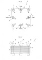
- FIG. 1A is a plan view of a solid oxide fuel cell of Example 1, and FIG. 1B is a side view of the solid oxide fuel cell. It is explanatory drawing which shows the state which fractured
- 6B is an explanatory view showing a flow path of air. It is explanatory drawing which shows the manufacture procedure of a solid oxide fuel cell. It is explanatory drawing which shows the state (formation procedure) of the seal
- 3 is a plan view showing a gas seal part of a solid oxide fuel cell of Example 2.
- FIG. 6 is a perspective view showing an air electrode frame used in the solid oxide fuel cell of Example 2.
- FIG. 6 is a plan view showing a gas seal portion of a solid oxide fuel cell of Example 3.
- FIG. 6 is a plan view showing a gas seal portion around a nut of a solid oxide fuel cell of Example 4.
- the fuel cell 1 is a device that generates power by receiving supply of a fuel gas (for example, hydrogen) and an oxidant gas (for example, air).
- the fuel cell 1 includes a fuel cell stack 5 in which a plurality of (for example, 24 stages) flat plate fuel cell cells 3 as power generation units (power generation cells) are stacked, and the fuel cell stack 5 in a stacking direction (in FIG. 1B).
- a plurality of bolts 11 to 18 penetrating in the vertical direction and nuts 19 (generic names) screwed to ends (here, upper portions) of the bolts 11 to 18 are provided.
- the fuel cell stack 5 has a plurality of fuel cells 3 electrically connected in series.
- a nut 19 that is screwed into the second bolt 12 among the bolts 11 to 18 is provided with a fuel gas introduction pipe 21 that supplies fuel gas to the fuel cell 1.
- the nut 19 that is screwed to the bolt 14 is provided with an air introduction pipe 23 that supplies an oxidant gas (hereinafter simply referred to as air) to the fuel cell 1, and the nut 19 that is screwed to the sixth bolt 16 is A fuel gas discharge pipe 25 that discharges the fuel gas after power generation from the fuel cell 1 is provided, and an air discharge pipe 27 that discharges the air after power generation from the fuel cell 1 to the nut 19 that is screwed into the eighth bolt 18. Is provided.
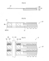
- each fuel cell 3 constituting the fuel cell stack 5 is a so-called fuel electrode support membrane type plate-like fuel cell 3, and the fuel cell 3 includes a pair of upper and lower fuel cells 3.
- the fuel flow path 31 in which the fuel gas flows and the air flow path 33 in which the air flows are provided separately between the interconnectors 43 and 43 (having conductivity).
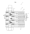
- the fuel cell 3 has a plate-shaped fuel electrode (anode) 35 disposed on the fuel flow path 31 side, and a thin solid electrolyte layer on the surface of the fuel electrode 35 (upper side in FIG. 2).
- a solid oxide layer 37 is formed.
- a thin air electrode (cathode) 39 is formed on the surface of the solid oxide layer 37 (upper side in FIG. 2).
- the fuel electrode 35, the solid oxide layer 37, and the air electrode 39 are referred to as a cell body (single cell) 41.
- a fuel electrode side current collector 53 (having air permeability made of a metal mesh or the like) is disposed in the fuel cell 3 between the fuel electrode 35 and the interconnector 43 on the lower side of FIG.
- a large number of block-shaped convex portions serving as the air electrode side current collector 55 are integrally formed.
- the fuel cell 3 includes a sheet-like gas seal portion 45 on the air electrode 39 side and an outer edge portion (specifically, solid oxidation) of the cell body (single cell) 41 so as to surround the cell body (single cell) 41.
- a separator 47 joined to the upper surface of the outer edge of the material layer 37 and blocking between the air flow path 33 and the fuel flow path 31, and a fuel electrode frame 49 disposed on the fuel flow path 31 side. These are laminated to form a single unit.
- the plate members (having the same conductivity as the interconnector 43) at both ends in the stacking direction of the fuel cell 1 are referred to as end plates 51.
- the solid oxide layer 37 materials such as YSZ, ScSZ, SDC, GDC, and perovskite oxide can be used.
- the fuel electrode 35 Ni and a cermet of Ni and ceramic can be used, and as the air electrode 39, a perovskite oxide, various noble metals and cermets of noble metal and ceramic can be used.
- the interconnector 43, the end plate 51, the separator 47, and the fuel electrode frame 49 for example, a metal plate made of ferritic stainless steel such as SUS430 and SUS444 can be used.
- a metal plate made of ferritic stainless steel such as SUS430 and SUS444 can be used.
- Each of the bolts 11 to 18 and the nut 19 can be a metal member made of, for example, Inconel (registered trademark).
- thermal expansion coefficient of each metal plate a range of 8 to 14 ⁇ 10 ⁇ 6 / K (20 to 300 ° C.) can be adopted, and the thermal expansion coefficients of the bolts 11 to 18 and the nut 19 are For example, 16 ⁇ 10 ⁇ 6 / K (20 to 300 ° C.) having a large thermal expansion coefficient can be employed.
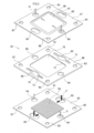
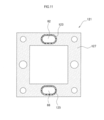
- each member which comprises the fuel cell 3 is demonstrated in detail. Since the planar shape of the fuel battery cell 3 is square, the planar shape of each member constituting the fuel battery cell 3 is also square.
- the interconnector 43 on which the fuel electrode side current collector 53 is placed, the fuel electrode frame 49, and the separator 47 joined to the cell body (single cell) 41 are the same.
- the fuel cell cassette 57 is laminated in the vertical direction in the figure and integrated (by laser welding described later).
- the interconnector 43 is a square plate member, and through holes (first to eighth insertion holes) 61 to 68 through which the bolts 11 to 18 are inserted are formed at substantially equal intervals.
- insertion holes 61 to 68 (the same numbers are assigned to the insertion holes in each member) are formed at eight positions at positions corresponding to the four corners of the interconnector 43 and the midpoint of each side.
- the first, third, fifth, and seventh insertion holes 61, 63, 65, and 67 at the four corners are round holes that are not used as gas flow paths for fuel gas or air.
- the second and sixth insertion holes 62 and 66 provided on the opposite sides are oval having a long dimension along the side.
- the second insertion hole 62 transmits the fuel gas to the fuel cell 3.
- This is a fuel gas introduction path (fuel manifold on the fuel gas introduction side) to be introduced into the internal fuel flow path 31.
- the sixth insertion hole 66 is a fuel gas discharge path (fuel manifold on the fuel gas discharge side) for discharging the fuel gas from the fuel flow path 31 in the fuel cell 3.
- the fourth and eighth insertion holes 64 and 68 provided on the other opposing sides are round holes, and among these, the fourth insertion hole 64 allows air to enter the air flow path 33 in the fuel cell 3.
- the eighth insertion hole 68 is an air discharge path (air manifold on the air discharge side) for discharging air from the air flow path 33 in the fuel cell 3.
- the fuel manifolds and air manifolds and the bolts 11 to 18 inserted through the fuel manifolds and air manifolds are arranged coaxially.
- the fuel electrode frame 49 is a square frame-shaped plate member, and the first to eighth insertion holes 61 to 68 through which the bolts 11 to 18 are inserted are formed on the outer edge portion thereof.
- the second and sixth insertion holes 62 and 66 are formed with slits 71 and 73 (through holes) in the longitudinal direction, and the interconnector 43 side (lower side in the figure) of the fuel electrode frame 49.
- a plurality of grooves 77 and 79 (which serve as fuel gas flow paths) are formed so that the slits 71 and 73 communicate with the opening 75 in the frame.
- the separator 47 is a square frame-shaped plate material, and the first to eighth insertion holes 61 to 68 through which the bolts 11 to 18 are inserted are formed on the outer edge portion thereof. And the cassette 57 of the structure mentioned above is laminated
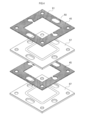
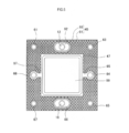
- the gas seal portion 45 in the first embodiment includes a sheet-like compression seal material 91 made of mica and a glass seal material 93 made of glass. Note that the compression seal material 91 and the glass seal material 93 have electrical insulation.
- an interconnector 43 or end plate 51 or a separator 47 constituting the fuel cell stack 5 is provided.
- the glass sealing material 93 and the compression sealing material 91 are seen from the inside along a plane (plane on which the paper surface spreads) in which the fuel cells 3 extend so as to be sandwiched from the stacking direction and surround the fuel manifold from the outer side (outer peripheral side). They are arranged in parallel in order.
- the fuel manifold when viewed from the axial direction of the bolts 12 and 16, and hence the second and sixth insertion holes 62 and 66, which are fuel manifolds (in plan view), the fuel manifold is surrounded from a radial direction perpendicular to the axial direction. Further, the glass sealing material 93 and the compression sealing material 91 are arranged concentrically. That is, the annular glass seal material 93 is disposed on the inner side, and the compression seal material 91 is disposed so as to surround the entire outer peripheral side thereof.
- the compression seal material 91 is a square frame-shaped member, and the first to eighth insertion holes 61 to 68 through which the bolts 11 to 18 are inserted are formed on the outer edge portion thereof.
- the compression seal material 91 has a thickness of 0.40 mm before assembling and 0.36 mm after assembling.
- first, third, fifth, and seventh insertion holes 61, 63, 65, and 67 are round holes
- fourth and eighth insertion holes 64 and 68 are round holes having a larger diameter
- the second and sixth insertion holes 62 and 66 are oval long holes.
- the compression seal material 91 is provided with communication passages 95 and 97 as air flow paths so as to communicate with the fourth and eighth insertion holes 64 and 68 and the opening 99 in the frame, respectively. .
- annular glass sealing material 93 having a thickness of 0.3 mm and a width of 3.0 mm is disposed so as to surround it.
- the glass sealing material 93 is a gas sealing material containing glass (for example, containing glass as a main component).
- a gas sealing material containing glass for example, containing glass as a main component.
- a commercially available crystallized glass preform preliminary sintered body
- its softening point is, for example, 770 ° C.
- the glass sealing material 93 has a thermal expansion coefficient close to that of the surrounding metal plate (for example, ferritic stainless steel), for example, a thermal expansion coefficient of 8 to 14 ⁇ 10 ⁇ 6 / K (20 to 300 ° C.) is desirable (for example, 11 ⁇ 10 ⁇ 6 / K (20 to 300 ° C.)).
- a thermal expansion coefficient close to that of the surrounding metal plate for example, ferritic stainless steel
- a thermal expansion coefficient of 8 to 14 ⁇ 10 ⁇ 6 / K (20 to 300 ° C.) is desirable (for example, 11 ⁇ 10 ⁇ 6 / K (20 to 300 ° C.)).
- G018-311 manufactured by SCHOTT can be used.
- the operating temperature of the fuel cell 1 is, for example, 700 ° C., but is approximately 650 ° C. in the vicinity of the gas seal portion 45. Therefore, as the glass seal material 93, the softening point is higher than the temperature of the gas seal portion 45 during operation. Higher ones are used.
- a groove (not shown) is formed in the axial direction at the tip of the second bolt 12 (upward in the figure), and the space in the fuel gas introduction pipe 21 and the second insertion hole 62 are formed through this groove.
- the inside communicates (the fuel gas discharge side, the air introduction side and the discharge side have the same structure).
- This fuel gas is introduced into the fuel flow path 31 inside the fuel cell 3 from the second insertion hole 62 via the groove 77 of the fuel electrode frame 49 of each fuel cell 3. Thereafter, the remaining fuel gas that has contributed to power generation in the fuel cell 3 is inserted through the other groove 79 of the fuel electrode frame 49 through the sixth bolt 16 (which is a discharge-side fuel manifold). The fuel gas is discharged from the fuel gas discharge pipe 25 to the outside of the fuel cell stack 5 through the six insertion holes 66.
- Air flow path> As shown in FIG. 6B, the air introduced into the fuel cell stack 5 from the air introduction pipe 23 is introduced into the fourth insertion hole 64 through which the fourth bolt 14 is inserted (which is an air manifold on the introduction side). .
- This air is introduced from the fourth insertion hole 64 into the air flow path 33 inside the fuel cell 3 through the communication passage 95 of the compression seal material 91 of each fuel cell 3. Thereafter, the remaining air that has contributed to power generation in the fuel cell 3 is inserted into the eighth bolt 18 through the other communication passage 97 of the compression seal material 91 (which is an air manifold on the discharge side). The air is discharged from the air discharge pipe 27 to the outside of the fuel cell stack 5 through the eight insertion holes 68.
- a method for manufacturing the fuel cell 1 will be described.
- a cell body (single cell) 41 in which a fuel electrode 35, a solid oxide layer 37, and an air electrode 39 are integrated is manufactured according to a conventional method.
- a frame-like separator 47 is brazed to the outer edge of the (single cell) 41.
- the fuel electrode frame 49 is sandwiched between the separator 47 and the interconnector 43 (or end plate 51), and the fuel electrode frame 49, the separator 47, and the interconnector 43 (or end plate) are laser-welded. 51) are integrally joined to produce a fuel cell cassette 57.
- the periphery of the second and sixth insertion holes 62 and 66 that are fuel manifolds and the fourth and eighth insertion holes 64 and 68 that are air manifolds are joined in an annular shape by laser welding, and the separator 47. And the outer edge of the interconnector 43 (or the end plate 51) are joined in an annular shape.
- the gas seal portion 45 (the material to be formed) made of the compression seal material 91 and the glass seal material 93 (to be the glass material) is disposed between the cassettes 57 of the fuel cell.
- the annular glass sealing material 93 (and so on) is provided so as to completely surround the fuel manifold (second and sixth insertion holes 62 and 66) on the same plane of the surface of each separator 47.
- the compression sealing material 91 is disposed so as to completely surround the periphery of the glass sealing material 93 (becoming glass material).
- the bolts 11 to 18 are inserted into the insertion holes 61 to 68, and the bolts 11 to 18 and the nut 19 are tightened, so that the fuel cell stack 5 is stacked in the stacking direction (up and down in FIG.
- the fuel cell stack 5 is integrated.
- the thickness of the compression sealant 91 is 0.36 mm, and the thickness of the glass sealant 93 (before softening) is larger than 0.30 mm. 43 (or end plate 51) has a slight gap.
- the fuel cell stack 5 (specifically, the glass sealing material 93 (becoming glass material)) is heated to, for example, 850 ° C. above the crystallization temperature of the glass for 2 hours to crystallize the glass.
- the glass sealing material 93 softens and becomes rounded by its surface tension as shown in FIG.
- the upper interconnector 43 (or the end plate 51) is contacted. Further, the glass is crystallized by heating at 850 ° C. for 2 hours.
- the glass sealing material 93 is firmly bonded to the separator 47 and the interconnector 43 (or the end plate 51).
- the glass sealing material 93 is softened when the glass is heated, as described above, the thermal expansion coefficients of the bolts 11 to 18 are arranged in the stacking direction such as the separator 47, the interconnector 43, and the fuel electrode frame 49.
- the fuel cell stack 5 Since the thermal expansion coefficient of the metal plate and the thermal expansion coefficient of the glass seal material 93 are larger than each other, the fuel cell stack 5 is loosened when the glass is heated (the pressing force of the bolts 11 to 18 is reduced, It ’s not lost.) Thereafter, when cooled, the bolts 11 to 18 and the like shrink in the stacking direction (return to the original) to form a compression field, so that the glass seal material 93 is sealed in a compressed state (that is, by glass). Sealed).
- annular glass sealing material 93 is disposed along a plane (that is, a radial direction of each manifold) in which the fuel cells 3 spread so as to surround each manifold (for example, in a plan view shown in FIG. 5).
- Compression sealing materials 91 are arranged in parallel so as to surround the glass sealing material 93 from the radial direction on the same plane.
- the compression seal material 91 can suppress an excessive force from being applied to the glass seal material 93, so that the glass seal material 93 can be prevented from cracking. Gas leakage can be suitably prevented.
- the compression seal material 91 suppresses excessive deformation of the glass seal material 93, so that the glass spreads around and the electrical connectivity is reduced. Can be prevented.
- the occurrence of gas leakage of the fuel gas can be suitably prevented, so that the power generation efficiency is high and there is no need for post-processing of the leaked gas (or post-processing is easy). Has an effect.
- the fuel cell stack 5 is fastened and fixed by the bolts 11 to 18 and the nut 19, so that there is an advantage that the fixing is easy and can be surely fixed.
- the temperature of the fuel cell 1 varies according to the operation (ON) and stop (OFF) of the fuel cell 1, but in the first embodiment, the above-described configuration (relation of the thermal expansion coefficient of each part). Even if the temperature fluctuates, the glass sealing material 93 and the like can always be pressed, so that there is an advantage that gas leakage can be prevented. [Example 2] Next, the second embodiment will be described, but the description of the same contents as the first embodiment will be omitted.
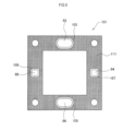
- the second embodiment is different from the first embodiment in the configuration of the gas seal portion of the fuel cell, so the gas seal portion will be described.
- the same number as the said Example 1 is used.
- the second and sixth insertion holes 62 and 66 that are fuel manifolds are surrounded by annular glass seal materials 103 and 105.
- the periphery of the fourth and eighth insertion holes 64 and 68 that are air manifolds is also surrounded by the annular glass seal materials 107 and 109.
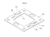
- the compression seal material 111 has a rectangular frame shape as in the first embodiment, and is disposed so as to surround the outer periphery of each glass seal material 103, 105, 107, 109. Further, in the second embodiment, as shown in FIG. 10, the gap between the gas seal portion 101 and the separator 47 is the same as that of the frame-shaped fuel electrode frame 49 of the first embodiment (however, the direction is 90 degrees in plan view). An air electrode frame 118 (which is different) is disposed (the same applies to the third embodiment).
- the air electrode frame 118 includes slits 113 and 114 which are through holes extending along the sides from the fourth and eighth insertion holes 64 and 68 and grooves 116 and 117 extending from the slits 113 and 114 to the air electrode 39 side. It is a frame-like member, and communicates the fourth and eighth insertion holes 64 and 68 and the air electrode 39 side through the slits 113 and 114 and the grooves 116 and 117 of the air electrode frame 118.
- the second embodiment has the same effects as the first embodiment and can prevent not only fuel gas leak but also air leak. Therefore, since the gas flow rate can be adjusted with high accuracy, there is an advantage that the fuel cell 1 can be operated more precisely.
- Example 3 Next, the third embodiment will be described, but the description of the same contents as the first embodiment will be omitted.
- the third embodiment is different from the first embodiment in the configuration of the gas seal portion of the fuel cell, so the gas seal portion will be described.
- the same number as the said Example 1 is used.
- the gas seal portion 121 of the fuel cell 1 of the third embodiment is composed of compression seal materials 123 and 125 and a glass seal material 127 made of the same material as in the first embodiment. The arrangement is reversed.
- annular compression seal materials 123 and 125 are disposed around the place where the glass seal material is used in the first embodiment, that is, around the second and sixth insertion holes 62 and 66 that are fuel manifolds.
- a rectangular frame-shaped glass seal material 127 is disposed at a place where the compression seal material is used in the first embodiment, that is, surrounding the compression seal materials 123 and 125.
- the third embodiment has the same effect as the first embodiment, and has many advantages such as excellent gas sealability since there are many glass sealing portions.
- the fourth embodiment will be described, but the description of the same contents as the first embodiment will be omitted.
- a plurality of bolts are provided so as to penetrate the fuel cell stack 5 having the same configuration as that of the first embodiment in the stacking direction. 131 is arranged.
- annular first gas seal portion 137 is provided between a nut 133 screwed into the bolt 131 and one end plate 135 (upper side in the figure).
- An annular second gas seal portion 143 (similar to the first gas seal portion 137) is provided between the head 139 and the other end plate 141 (downward in the figure).
- the members constituting the fuel cell of the present invention include the bolt 131 (including the head 139), the nut 133, the end plates 135 and 141, and the like.
- the insertion hole 145 through which the bolt 131 is inserted is the same fuel manifold as in the first embodiment, but both the fuel manifold and the air manifold may be used as in the second embodiment.
- the first gas seal portion 137 surrounds the periphery of the compression seal member 147 and the annular compression seal member 147 arranged so as to surround the bolt 131 (and the insertion hole 145), and also includes the nut 133 and the end.
- An annular glass sealing material 149 joined to the plate 135.
- the second gas seal portion 143 includes an annular compression seal material 151 disposed so as to surround the bolt 131 (and the second and sixth insertion holes 62 and 66), and the periphery of the compression seal material 151.
- An annular glass sealing material 153 which is enclosed and joined to the head 139 of the bolt 131 and the end plate 141 is formed.
- the glass sealing materials 149 and 153 for example, the same material as the glass sealing material 93 of the first embodiment can be used.
- the 1st gas seal part 137 and the 2nd gas seal part 143 which are the principal parts of the present Example 4 are demonstrated in detail.
- one of the second insertion hole 62 and the sixth insertion hole 66 (upper part in the drawing) constituting the fuel manifold is open ends (openings) 62a, 66a.
- the first gas seal portion 137 is provided for gas sealing
- the second gas seal portion 143 is provided for gas sealing the other open ends (opening portions) 62b and 66b. Yes.
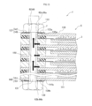
- the first gas seal portion 137 is disposed on one end plate 135 on the upper side of FIG. 13 (on one opening 62a, 66a side of the second and sixth insertion holes 62, 66 which are fuel manifolds). ) Between each nut 133, that is, between the upper surface 135 a of one end plate 135 and the lower surface 133 a of each nut 133, a gas seal is provided.
- the nut 133 is provided so as to cover the openings 62a and 66a on one side (upper side of FIG. 13) of the fuel manifold when viewed from the upper side of FIG. 13 (in plan view).
- the second gas seal portion 143 is disposed on the other end plate 141 in the lower part of FIG. 13 (on the other opening portions 62b and 66b side of the second and sixth insertion holes 62 and 66 which are fuel manifolds).
- a gas seal is provided between the heads 139 of the bolts 131, that is, between the lower surface 141b of the other end plate 141 and the upper surface 139b of the heads 139 of the bolts 131.
- the head portion 139 of the bolt 131 is provided so as to cover the openings 62b and 66b on the other side (lower side in FIG. 13) of the fuel manifold as viewed from the lower side in FIG. 13 (in plan view).
- the 1st gas seal part 137 is the circumference
- the end plate 135 and the periphery of the portion of the bolt 131 that protrudes from the fuel cell stack 5 (upward in FIG. 13) in the radial direction are surrounded by the outer side (outer peripheral side).
- the compression seal material 147 and the glass seal material are sandwiched by the nut 133 from the stacking direction of the fuel cells 3 (up and down direction in FIG. 13) and along the plane in which the fuel cells 3 spread (a plane perpendicular to the stacking direction). 149 are arranged in parallel in order.
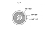
- FIG. 14 when viewed from the axial direction of the bolt 131 (in a plan view), it surrounds the periphery of the axial portion 150 of the bolt 131, that is, the axial direction of the axial portion 150 is perpendicular to the axial direction.
- the compression sealing material 147 and the glass sealing material 149 are arranged concentrically so as to surround from. That is, an annular compression seal material 147 is disposed on the inner side, and an annular glass seal material 149 is disposed so as to surround the entire outer peripheral side thereof.
- the second gas seal portion 143 is arranged on the same plane (viewed from the vertical direction in FIG. 13: in plan view), and the shaft portion 150 of each bolt 131 (and each insertion hole 62, 66) and an annular compression seal material 151 arranged so as to surround the periphery of the compression seal material 151, and arranged so as to surround the periphery of the compression seal material 151 (joined to the head 139 and the end plate 141 of each bolt 131). It is comprised from the cyclic
- the end plate 141 and the periphery of the portion of the bolt 131 that protrudes from the fuel cell stack 5 (downward in FIG. 13) in the radial direction are surrounded by the end plate 141 and the outer periphery.
- the compression seal material 151 and the glass seal material 153 are arranged in parallel in order along the plane in which the fuel cell 3 spreads while being sandwiched by the heads 139 of the bolts 131 from the stacking direction of the fuel cells 3. .
- FIG. 14 when viewed from the axial direction of the bolt 131 (in plan view), it surrounds the periphery of the axial portion 150 of the bolt 131, that is, the diameter of the axial portion 150 is perpendicular to the axial direction.
- the compression seal material 151 and the glass seal material 153 are arranged concentrically so as to surround from the direction. That is, an annular compression seal material 151 is disposed on the inner side, and an annular glass seal material 153 is disposed so as to surround the entire outer periphery thereof.
- the compression seal materials 147 and 151 are sheet-like members made of mica, like the gas seal portion 45, and the glass seal materials 149 and 153 are It is composed of glass. Both compression sealing materials 147 and 151 and the glass sealing materials 149 and 153 also have electrical insulation.
- each compression seal material 147, 151 is a ring with an outer diameter of 17 mm ⁇ an inner diameter of 11 mm), the thickness before assembly is 0.5 mm, and the thickness after assembly (after compression) is 0.4 mm. .
- each glass sealing material 149,153 is a gas sealing material containing glass (for example, glass is the main component).
- a gas sealing material containing glass for example, glass is the main component.
- a commercially available crystallized glass preform preliminarily sintered body
- its softening point is, for example, 770 ° C.
- glass sealing materials 149 and 153 those having a thermal expansion coefficient close to that of a surrounding metal plate (for example, made of ferritic stainless steel), for example, a thermal expansion coefficient of 8 to 14 ⁇ 10 ⁇ 6 / K ( 20 to 300 ° C.) is desirable (for example, 11 ⁇ 10 ⁇ 6 / K (20 to 300 ° C.)).
- a thermal expansion coefficient of 8 to 14 ⁇ 10 ⁇ 6 / K 20 to 300 ° C.
- 11 ⁇ 10 ⁇ 6 / K (20 to 300 ° C.
- G018-311 manufactured by SCHOTT can be used.
- the operating temperature of the fuel cell 1 is, for example, 700 ° C., but is around 640 ° C. in the vicinity of the first and second gas seal portions 137, 143. Therefore, as the glass seal materials 149, 153, Those having a softening point higher than the temperature of the first and second gas seal portions 137 and 143 are used. Further, different materials (for example, materials having different softening points) may be used as the glass seal material 93 of the gas seal portion 45 and the glass seal materials 149 and 153 of the first and second gas seal portions 137 and 143.
- the first, third, fourth, fifth, seventh, and eighth insertion holes 61, 63, 64, 65, 67, and 68 through which the fuel gas does not flow are screwed into these bolts 131. Since there is no need to gas seal the nut 133 to be used, only a compression seal material (not shown) made of the same annular mica as that used in the first and second gas seal portions 137 and 143 is used as a spacer. Is used.
- the gas having the same configuration as the first and second gas seal portions 137 and 143 so that the openings of the fourth and eighth insertion holes 64 and 68 corresponding to the air manifold are gas-sealed in the same manner as the fuel manifold.
- a seal portion (not shown) may be provided.
- a gas seal portion (not shown) having the same configuration as the first and second gas seal portions 137 and 143 is provided so that all the openings of the first to eighth insertion holes 61 to 68 are gas-sealed. It may be provided.
- the first gas seal portion 137 is formed, as shown in FIG. 14, an annular compression seal material 147 is arranged around the bolt 131, and an annular compression seal material 147 is arranged around A glass sealing material 149 (becoming glass material) is disposed.
- the glass sealing materials 149 and 153 are softened by heating, joined to surrounding members, and then cooled.
- the fourth embodiment has the same effect as the first embodiment, and has the advantage that gas can be effectively prevented from leaking from the gap between the fuel cell stack 5 and the head 139 of the nut 133 or the bolt 131. is there.
- Example of this invention is not limited to the said Example, A various aspect can be taken.
- a method of pressing the fuel cell stack in the stacking direction in addition to the tightening by screwing of the bolt and nut described above, for example, a method of putting a weight so as to apply a load in the stacking direction, a spring is used. Examples include a method of pressing in the stacking direction.
- each fuel manifold or air manifold and each bolt inserted through each fuel manifold or air manifold may not be arranged coaxially (not shown).
- Each bolt may be arranged outside each fuel manifold or air manifold (not shown).
- the present invention is not limited to a solid oxide fuel cell (SOFC), but is applied to a high-temperature type fuel cell having an operating temperature range of about 600 ° C. or more, such as a molten carbonate fuel cell (MCFC). Is possible.
- SOFC solid oxide fuel cell
- MCFC molten carbonate fuel cell
Abstract
Description
シール材の割れを防止するとともに、ガス漏れを好適に防止できる燃料電池及びその製造方法を提供することが望ましい。 Furthermore, when a ceramic annular sealing material is used, if a strong force is applied, the sealing material may be cracked and gas leakage may occur.
It is desirable to provide a fuel cell and a method for manufacturing the same that can prevent cracking of the sealing material and suitably prevent gas leakage.
(2)本発明の第2局面の燃料電池では、前記少なくとも一方の前記積層方向に延びるマニホールドの周囲に、環状に前記ガラスシール材が配置されているとともに、該ガラスシール材の外周側に、前記コンプレッションシール材が配置されていてもよい。 Here, the manifold is a flow path of gas (fuel gas or oxidant gas) extending in the stacking direction, and the gas flow path is branched in the middle of the flow path.
(2) In the fuel cell according to the second aspect of the present invention, the glass sealing material is annularly disposed around the at least one manifold extending in the stacking direction, and on the outer peripheral side of the glass sealing material, The compression seal material may be disposed.
この場合、ボルト(及びボルトに螺合するナット)によって、燃料電池を締め付け押圧して固定するので、固定が容易であるとともに、確実に固定できるという利点がある。 (4) In the fuel cell according to the fourth aspect of the present invention, the fuel cell may be assembled by being pressed in the stacking direction by bolting.
In this case, since the fuel cell is fastened and pressed by a bolt (and a nut screwed to the bolt), there is an advantage that the fixing is easy and the fixing can be surely performed.
燃料電池を構成する部材としては、燃料極側の空間(燃料流路)と空気極側の空間(空気流路)とを分離するセパレータや、燃料電池の構成単位である燃料電池セルを区分するとともに、各燃料電池セル間の導通を確保するインターコネクタや、燃料電池の積層方向の端部を構成する部材であるエンドプレートが挙げられる。 The above description exemplifies members constituting the fuel cell.
As a member constituting the fuel cell, a separator that separates a space on the fuel electrode side (fuel flow path) and a space on the air electrode side (air flow path) and a fuel cell that is a constituent unit of the fuel cell are classified. In addition, there are an interconnector that ensures conduction between the fuel cells and an end plate that is a member that constitutes an end portion of the fuel cell in the stacking direction.
なお、以下に、本発明の各構成について説明する。
前記燃料電池としては、固体酸化物形燃料電池(SOFC)が挙げられる。 By this manufacturing method, the above-described fuel cell can be preferably manufactured.
Hereinafter, each configuration of the present invention will be described.
Examples of the fuel cell include a solid oxide fuel cell (SOFC).
ガラスシール材としては、通常のガラス(例えば非結晶化ガラス)を用いることができるが、それ以外に、結晶化ガラス、部分結晶化ガラス(半結晶化ガラス)を用いることができる。また、ガラス成分以外に、セラミックなど各種の材料を添加してもよい。 As this compression sealing material, in addition to gas sealing properties, a material having a function as an elastic stopper that is not compressed more than a certain amount, an electrical insulating property, or the like can be adopted.
As the glass sealing material, normal glass (for example, non-crystallized glass) can be used. In addition, crystallized glass and partially crystallized glass (semi-crystallized glass) can be used. In addition to the glass component, various materials such as ceramics may be added.
各燃料電池セルを積層方向から押圧する部材として、ボルトを使用する場合には、ボルトの熱膨張係数としてガラスシール材の熱膨張係数より大きいものが好ましい。これにより、燃料電池の運転時等(ガラスが軟化しないとき)に、ボルトによってガラスシール材に圧縮応力をかけることができるので、(引張応力が加わる場合に比べて)ガラスの割れを低減できる。 The glass seal material may be disposed only around the fuel manifold.
When a bolt is used as a member for pressing each fuel cell from the stacking direction, it is preferable that the thermal expansion coefficient of the bolt is larger than the thermal expansion coefficient of the glass sealing material. Thereby, since the compressive stress can be applied to the glass sealing material by the bolt during the operation of the fuel cell (when the glass is not softened), the cracking of the glass can be reduced (compared to the case where the tensile stress is applied).
3…燃料電池セル
5…燃料電池スタック
11、12、13、14、15、16、17、18、131…ボルト
19、133…ナット
35…燃料極
37…固体酸化物層
39…空気極
41…セル本体(単セル)
43…インターコネクタ
45、101、121、137、143…ガスシール部
47…セパレータ
49…燃料極フレーム
51、135、141…エンドプレート
57…カセット
61、62、63、64、65、66、67、68、145…挿通孔
91、111、123、125、147、151…コンプレッションシール材
93、103、105、107、109、127、149、153…ガラスシール材 DESCRIPTION OF
43 ...
[実施例1]
a)まず、本実施例1の固体酸化物形燃料電池の概略構成について説明する。なお、以下では「固体酸化物形」を省略する。 Embodiments of a fuel cell to which the present invention is applied and a method for manufacturing the same will be described below with reference to the drawings. In the following examples, a solid oxide fuel cell (SOFC) will be described as an example of the fuel cell.
[Example 1]
a) First, the schematic configuration of the solid oxide fuel cell of Example 1 will be described. In the following, “solid oxide form” is omitted.
この燃料電池1は、発電単位(発電セル)である平板形の燃料電池セル3が、複数個(例えば24段)積層された燃料電池スタック5と、燃料電池スタック5を積層方向(図1Bの上下方向)貫く複数のボルト11~18と、各ボルト11~18の端部(ここでは上部)に螺合する各ナット19(総称)とを備えている。 As shown in FIGS. 1A-1B, the
The
また、図1Aに示す様に、各ボルト11~18のうち、第2ボルト12に螺合するナット19には、燃料ガスを燃料電池1に供給する燃料ガス導入管21が設けられ、第4ボルト14に螺合するナット19には、酸化剤ガス(以下、単に空気と記す)を燃料電池1に供給する空気導入管23が設けられ、第6ボルト16に螺合するナット19には、発電後の燃料ガスを燃料電池1から排出する燃料ガス排出管25が設けられ、第8ボルト18に螺合するナット19には、発電後の空気を燃料電池1から排出する空気排出管27が設けられている。 The
As shown in FIG. 1A, a
図2に示す様に、前記燃料電池スタック5を構成する各燃料電池セル3は、いわゆる燃料極支持膜形タイプの板状の燃料電池セル3であり、この燃料電池セル3には、上下一対の(導電性を有する)インターコネクタ43、43の間に、燃料ガスが流れる燃料流路31と空気が流れる空気流路33とが分離して設けられている。 Each configuration will be described below.
As shown in FIG. 2, each
ここで、固体酸化物層37としては、YSZ、ScSZ、SDC、GDC、ペロブスカイト系酸化物等の材料が使用できる。また、燃料極35としては、Ni及びNiとセラミックとのサーメットが使用でき、空気極39としては、ペロブスカイト系酸化物、各種貴金属及び貴金属とセラミックとのサーメットが使用できる。 The plate members (having the same conductivity as the interconnector 43) at both ends in the stacking direction of the
Here, as the
なお、燃料電池セル3の平面形状は正方形であるので、燃料電池セル3を構成する各部材の平面形状も正方形である。 Below, each member which comprises the
Since the planar shape of the
また、対向する辺に設けられた第2、第6挿通孔62、66は、辺に沿った寸法が長い長円形である、このうち、第2挿通孔62が、燃料ガスを燃料電池セル3内の燃料流路31に導入する燃料ガスの導入路(燃料ガスの導入側の燃料マニホールド)である。一方、第6挿通孔66が、燃料ガスを燃料電池セル3内の燃料流路31から排出する燃料ガスの排出路(燃料ガスの排出側の燃料マニホールド)である。 Of the insertion holes 61 to 68, the first, third, fifth, and seventh insertion holes 61, 63, 65, and 67 at the four corners are round holes that are not used as gas flow paths for fuel gas or air.
The second and sixth insertion holes 62 and 66 provided on the opposite sides are oval having a long dimension along the side. Of these, the
前記燃料極フレーム49は、正方形の枠状の板材であり、その外縁部には、前記ボルト11~18が貫挿される前記第1~第8挿通孔61~68が形成されている。 The fuel manifolds and air manifolds and the
The
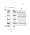
そして、上述した構成のカセット57は、図4に示すように、間にシート状のガスシール部45を介して積層されている。 The
And the
<燃料ガスの流路>
図6Aに示すように、燃料ガス導入管21から燃料電池スタック5内に導入された燃料ガスは、第2ボルト12が挿通される(導入側の燃料マニホールドである)第2挿通孔62に導入される。 b) Next, the gas flow path in the first embodiment will be briefly described.
<Flow path of fuel gas>
As shown in FIG. 6A, the fuel gas introduced into the
その後、燃料電池セル3内にて発電に寄与した残余の燃料ガスは、燃料極フレーム49の他の溝79を介して、第6ボルト16が挿通される(排出側の燃料マニホールドである)第6挿通孔66を介して、燃料ガス排出管25から燃料電池スタック5外に排出される。 This fuel gas is introduced into the
Thereafter, the remaining fuel gas that has contributed to power generation in the
図6Bに示すように、空気導入管23から燃料電池スタック5内に導入された空気は、第4ボルト14が挿通される(導入側の空気マニホールドである)第4挿通孔64に導入される。 <Air flow path>
As shown in FIG. 6B, the air introduced into the
その後、燃料電池セル3内にて発電に寄与した残余の空気は、コンプレッションシール材91の他の連通路97を介して、第8ボルト18が挿通される(排出側の空気マニホールドである)第8挿通孔68を介して、空気排出管27から燃料電池スタック5外に排出される。 This air is introduced from the
Thereafter, the remaining air that has contributed to power generation in the
図7Aに示すように、定法に従って、燃料極35と固体酸化物層37と空気極39とが一体となった(正方形の板状の)セル本体(単セル)41を作製し、このセル本体(単セル)41の外縁部に枠状のセパレータ47を、ろう付けする。 c) Next, a method for manufacturing the
As shown in FIG. 7A, a cell body (single cell) 41 in which a
なお、ガラスを加熱するとガラスシール材93が軟化するが、上述のように、ボルト11~18の熱膨張係数は、セパレータ47、インターコネクタ43、燃料極フレーム49等のような積層方向に配置された金属板の熱膨張係数や、ガラスシール材93の熱膨張係数より大きいので、ガラスの加熱時には、燃料電池スタック5は全体が緩んだ状態となる(ボルト11~18の押圧力は減るが、無くなっている訳ではない)。その後、冷却されると、ボルト11~18等が積層方向に縮んで(元に戻って)圧縮場となっているので、ガラスシール材93が圧縮された状態で封止される(即ちガラスによって封止される)。 Thereafter, by cooling, as shown in FIG. 8C, the
Although the
d)本実施例1の効果について説明する。
本実施例1では、燃料マニホールドである第2、第6挿通孔62、66と、空気マニホールドである第4、第8挿通孔64、68との周囲には、セパレータ47やインターコネクタ43(又はエンドプレート51)によって積層方向から挟まれるとともに、各マニホールドを囲むように、ガスシール部45が配置されている。 In this way, the gas seal configuration is realized and the
d) The effect of the first embodiment will be described.
In the first embodiment, around the second and sixth insertion holes 62 and 66 that are fuel manifolds and the fourth and eighth insertion holes 64 and 68 that are air manifolds, a
[実施例2]
次に、実施例2について説明するが、前記実施例1と同様な内容の説明は省略する。 Furthermore, the temperature of the
[Example 2]
Next, the second embodiment will be described, but the description of the same contents as the first embodiment will be omitted.
更に、本実施例2では、ガスシール部101とセパレータ47との間に、図10に示すように、実施例1の枠状の燃料極フレーム49と同様な(但し向きは平面視で90度異なっている)空気極フレーム118を配置している(実施例3も同様)。 The
Further, in the second embodiment, as shown in FIG. 10, the gap between the
[実施例3]
次に、実施例3について説明するが、前記実施例1と同様な内容の説明は省略する。 Therefore, the second embodiment has the same effects as the first embodiment and can prevent not only fuel gas leak but also air leak. Therefore, since the gas flow rate can be adjusted with high accuracy, there is an advantage that the
[Example 3]
Next, the third embodiment will be described, but the description of the same contents as the first embodiment will be omitted.
[実施例4]
次に、実施例4について説明するが、前記実施例1と同様な内容の説明は省略する。 Therefore, the third embodiment has the same effect as the first embodiment, and has many advantages such as excellent gas sealability since there are many glass sealing portions.
[Example 4]
Next, the fourth embodiment will be described, but the description of the same contents as the first embodiment will be omitted.
ここで、ボルト131が挿通される挿通孔145は、前記実施例1と同様な燃料マニホールドであるが、前記実施例2と同様に、燃料マニホールドと空気マニホールドの両方でもよい。 The members constituting the fuel cell of the present invention include the bolt 131 (including the head 139), the
Here, the insertion hole 145 through which the
図13に示す様に、本実施例4の燃料電池1では、燃料マニホールドを構成する第2挿通孔62及び第6挿通孔66の一方(同図上方)の開口端(開口部)62a、66aをガスシールするために、第1ガスシール部137が設けられ、他方(同図下方)の開口端(開口部)62b、66bをガスシールするために、第2ガスシール部143が設けられている。 b) Next, the 1st
As shown in FIG. 13, in the
同様に、第2ガスシール部143は、図13の下方の他方のエンドプレート141と(燃料マニホールドである第2、第6挿通孔62、66の他方の開口部62b、66b側に配置された)各ボルト131の頭部139の間、つまり、他方のエンドプレート141の下面141bと各ボルト131の頭部139の上面139bとの間をガスシールするように設けられている。 The
Similarly, the second
このうち、第1ガスシール部137は、同一平面上にて(図13の上下方向から見て:平面視で)、各ボルト131の軸部150(及び各挿通孔62、66)の周囲を囲むように配置された環状のコンプレッションシール材147と、コンプレッションシール材147の外側の周囲を囲むように配置された(ナット133やエンドプレート135に接合した)環状のガラスシール材149とから構成されている。 The
Among these, the 1st
(1)例えば、燃料電池スタックを積層方向に押圧する方法としては、上述したボルト及びナットの螺合による締め付け以外に、例えば積層方向に荷重を加えるように錘を乗せる方法、バネを利用して積層方向に押圧する方法などが挙げられる。 As mentioned above, although the Example of this invention was described, this invention is not limited to the said Example, A various aspect can be taken.
(1) For example, as a method of pressing the fuel cell stack in the stacking direction, in addition to the tightening by screwing of the bolt and nut described above, for example, a method of putting a weight so as to apply a load in the stacking direction, a spring is used. Examples include a method of pressing in the stacking direction.
なお、各燃料マニホールドや空気マニホールドと、各燃料マニホールドや空気マニホールドに挿通される各ボルトとは、それぞれ同軸に配置されていなくともよい(図示せず)。また、各ボルトは、各燃料マニホールドや空気マニホールドの外部に配置されていてもよい(図示せず)。 (2) As the bolt, for example, a solid bolt (with no space inside), a hollow bolt (for example, with space along the axial direction), or the like can be adopted.
Each fuel manifold or air manifold and each bolt inserted through each fuel manifold or air manifold may not be arranged coaxially (not shown). Each bolt may be arranged outside each fuel manifold or air manifold (not shown).
Claims (7)
- 電解質層と、該電解質層の一方の面に設けられて燃料ガスに接する燃料極と、該電解質層の他方の面に設けられて酸化剤ガスに接する空気極と、を有する板状の燃料電池セルが、複数積層されるとともに、該燃料電池セルが前記積層方向から押圧された状態で組み付けられた平板型の燃料電池において、
前記燃料電池には、前記燃料極側の空間に連通する燃料マニホールド及び前記空気極側の空間に連通する酸化剤マニホールドのうち少なくとも一方が、前記積層方向に延びるように設けられており、
前記燃料マニホールド及び前記酸化剤マニホールドの少なくとも一方の前記積層方向に延びるマニホールドの周囲には、前記燃料電池を構成する部材によって前記積層方向から挟まれるとともに、前記少なくとも一方のマニホールドを囲むように、前記燃料電池セルが広がる平面に沿って、コンプレッションシール材とガラスシール材とが並列に配置されていることを特徴とする燃料電池。 A plate-like fuel cell having an electrolyte layer, a fuel electrode provided on one surface of the electrolyte layer and in contact with the fuel gas, and an air electrode provided on the other surface of the electrolyte layer and in contact with the oxidant gas In a flat plate type fuel cell in which a plurality of cells are stacked and assembled in a state where the fuel cell is pressed from the stacking direction,
In the fuel cell, at least one of a fuel manifold communicating with the space on the fuel electrode side and an oxidant manifold communicating with the space on the air electrode side is provided so as to extend in the stacking direction,
The periphery of the manifold extending in the stacking direction of at least one of the fuel manifold and the oxidant manifold is sandwiched from the stacking direction by members constituting the fuel cell and surrounds the at least one manifold. A fuel cell, wherein a compression sealing material and a glass sealing material are arranged in parallel along a plane in which the fuel cell extends. - 前記少なくとも一方の前記積層方向に延びるマニホールドの周囲に、環状に前記ガラスシール材が配置されるとともに、該ガラスシール材の外周側に、前記コンプレッションシール材が配置されていることを特徴とする請求項1に記載の燃料電池。 The glass sealing material is arranged in an annular shape around the at least one manifold extending in the stacking direction, and the compression sealing material is arranged on the outer peripheral side of the glass sealing material. Item 4. The fuel cell according to Item 1.
- 前記少なくとも一方の前記積層方向に延びるマニホールドの周囲に、環状に前記コンプレッションシール材が配置されるとともに、該コンプレッションシール材の外周側に、前記ガラスシール材が配置されていることを特徴とする請求項1に記載の燃料電池。 The compression seal material is arranged in an annular shape around the at least one manifold extending in the stacking direction, and the glass seal material is arranged on the outer peripheral side of the compression seal material. Item 4. The fuel cell according to Item 1.
- 前記燃料電池は、ボルト締めによって、前記積層方向に押圧されて組み付けられていることを特徴とする請求項1~3のいずれか1項に記載の燃料電池。 4. The fuel cell according to claim 1, wherein the fuel cell is assembled by being pressed in the stacking direction by bolting.
- 前記燃料電池を構成する部材は、前記燃料極側の空間と前記空気極側の空間とを分離するセパレータ、前記燃料電池セルを区分するとともに各燃料電池セル間の導通を確保するインターコネクタ、前記燃料電池の積層方向の端部を構成するエンドプレートのうち、少なくとも1種であることを特徴とする請求項1~4のいずれか1項に記載の燃料電池。 The members constituting the fuel cell include a separator that separates the space on the fuel electrode side and the space on the air electrode side, an interconnector that separates the fuel cell and ensures conduction between the fuel cells, The fuel cell according to any one of claims 1 to 4, wherein the fuel cell is at least one of end plates constituting end portions in the stacking direction of the fuel cells.
- 前記コンプレッションシール材と前記ガラスシール材とは、各燃料電池セル間を分離するインターコネクタ又は前記燃料電池の積層側の端部に配置されたエンドプレートと、前記電解質層に接合されて前記燃料極側の空間と前記空気極側の空間とを分離するセパレータとの間に配置されていることを特徴とする請求項1~5のいずれか1項に記載の燃料電池。 The compression sealing material and the glass sealing material are interconnectors that separate the fuel cells, or an end plate that is disposed at the end of the fuel cell on the stacking side, and the fuel electrode that is joined to the electrolyte layer. The fuel cell according to any one of claims 1 to 5, wherein the fuel cell is disposed between a separator separating the space on the side and the space on the air electrode side.
- 前記請求項1~6のいずれか1項に記載の燃料電池を製造する燃料電池の製造方法において、
前記燃料電池を構成する部材によって前記積層方向において挟まれるとともに、前記積層方向に沿って設けられた前記燃料マニホールド及び前記酸化剤マニホールドの少なくとも一方の周囲を囲むように、前記コンプレッションシール材と前記ガラスシール材となるガラス材料とを同一平面上に配置する第1工程と、
前記第1工程の後に、前記燃料電池の積層方向より圧力を加えて、前記コンプレッションシール材を押圧する第2工程と、
前記第2工程の後に、前記ガラス材料が軟化する温度以上で加熱し、その後冷却することによって、前記ガラスシール材を形成するとともに、該ガラスシール材を、前記燃料電池を構成する部材に接合する第3工程と、
を有することを特徴とする燃料電池の製造方法。 In the method for manufacturing a fuel cell for manufacturing the fuel cell according to any one of claims 1 to 6,
The compression sealant and the glass are sandwiched by the members constituting the fuel cell in the stacking direction and surround at least one of the fuel manifold and the oxidant manifold provided along the stacking direction. A first step of arranging a glass material to be a sealing material on the same plane;
A second step of pressing the compression seal material by applying pressure from the stacking direction of the fuel cell after the first step;
After the second step, the glass sealing material is formed by heating at a temperature higher than the temperature at which the glass material softens, and then cooling, and the glass sealing material is joined to a member constituting the fuel cell. A third step;
A method for producing a fuel cell, comprising:
Priority Applications (6)
| Application Number | Priority Date | Filing Date | Title |
|---|---|---|---|
| KR1020167002327A KR101903863B1 (en) | 2013-06-28 | 2014-06-27 | Fuel cell and method for manufacturing same |
| DK14816720.8T DK3016192T3 (en) | 2013-06-28 | 2014-06-27 | Fuel Cell and its Process |
| CN201480037221.4A CN105340116B (en) | 2013-06-28 | 2014-06-27 | Fuel cell and its manufacturing method |
| EP14816720.8A EP3016192B1 (en) | 2013-06-28 | 2014-06-27 | Fuel cell and method for manufacturing same |
| CA2916417A CA2916417C (en) | 2013-06-28 | 2014-06-27 | Fuel cell and method for manufacturing same |
| US14/901,292 US10693174B2 (en) | 2013-06-28 | 2014-06-27 | Fuel cell stack and method of producing the same |
Applications Claiming Priority (4)
| Application Number | Priority Date | Filing Date | Title |
|---|---|---|---|
| JP2013136710 | 2013-06-28 | ||
| JP2013-136710 | 2013-06-28 | ||
| JP2014005312 | 2014-01-15 | ||
| JP2014-005312 | 2014-01-15 |
Publications (1)
| Publication Number | Publication Date |
|---|---|
| WO2014208739A1 true WO2014208739A1 (en) | 2014-12-31 |
Family
ID=52142062
Family Applications (1)
| Application Number | Title | Priority Date | Filing Date |
|---|---|---|---|
| PCT/JP2014/067219 WO2014208739A1 (en) | 2013-06-28 | 2014-06-27 | Fuel cell and method for manufacturing same |
Country Status (8)
| Country | Link |
|---|---|
| US (1) | US10693174B2 (en) |
| EP (1) | EP3016192B1 (en) |
| JP (1) | JP6175410B2 (en) |
| KR (1) | KR101903863B1 (en) |
| CN (1) | CN105340116B (en) |
| CA (1) | CA2916417C (en) |
| DK (1) | DK3016192T3 (en) |
| WO (1) | WO2014208739A1 (en) |
Cited By (6)
| Publication number | Priority date | Publication date | Assignee | Title |
|---|---|---|---|---|
| WO2016031517A1 (en) * | 2014-08-27 | 2016-03-03 | 株式会社 村田製作所 | Fuel cell unit |
| JP2016170939A (en) * | 2015-03-12 | 2016-09-23 | 日本特殊陶業株式会社 | Fuel battery stack |
| WO2016175231A1 (en) * | 2015-04-30 | 2016-11-03 | 日本特殊陶業株式会社 | Fuel cell stack |
| JP2016225078A (en) * | 2015-05-28 | 2016-12-28 | 日本特殊陶業株式会社 | Fuel cell structure |
| JP2017010804A (en) * | 2015-06-23 | 2017-01-12 | 日本特殊陶業株式会社 | Method of manufacturing electrochemical reaction cell stack and electrochemical reaction cell stack |
| JP2021111473A (en) * | 2020-01-07 | 2021-08-02 | 東芝エネルギーシステムズ株式会社 | Solid oxide electrochemical stack |
Families Citing this family (16)
| Publication number | Priority date | Publication date | Assignee | Title |
|---|---|---|---|---|
| JP6236103B2 (en) * | 2016-03-01 | 2017-11-22 | 本田技研工業株式会社 | Fuel cell stack |
| KR102123715B1 (en) | 2016-08-16 | 2020-06-16 | 주식회사 엘지화학 | Solid oxide fuel cell |
| JP6511195B2 (en) | 2016-11-22 | 2019-05-15 | 日本特殊陶業株式会社 | Electrochemical reaction unit, electrochemical reaction cell stack, and method for producing electrochemical reaction unit |
| WO2018173134A1 (en) * | 2017-03-22 | 2018-09-27 | 株式会社 東芝 | Electrochemical cell stack |
| JP6893127B2 (en) * | 2017-06-14 | 2021-06-23 | 森村Sofcテクノロジー株式会社 | Electrochemical reaction unit and electrochemical reaction cell stack |
| KR102148066B1 (en) | 2017-07-13 | 2020-08-25 | 주식회사 엘지화학 | Fuel cell stack |
| KR102017578B1 (en) * | 2017-09-19 | 2019-09-03 | 주식회사 미코 | Fuelcell structure |
| JP6607977B2 (en) * | 2018-01-17 | 2019-11-20 | 本田技研工業株式会社 | Water electrolyzer |
| CN208444898U (en) * | 2018-06-13 | 2019-01-29 | 宁波索福人能源技术有限公司 | A kind of plate type solid-oxide fuel battery pile |
| WO2020004786A1 (en) * | 2018-06-29 | 2020-01-02 | 주식회사 미코 | Fuel cell structure |
| JP7241588B2 (en) * | 2019-03-29 | 2023-03-17 | 大阪瓦斯株式会社 | Electrochemical elements, electrochemical modules, electrochemical devices and energy systems |
| CN113632270A (en) * | 2019-06-13 | 2021-11-09 | 松下知识产权经营株式会社 | Electrochemical cell, electrochemical cell stack, method for producing electrochemical cell, and method for producing electrochemical cell stack |
| US11322771B2 (en) * | 2019-12-30 | 2022-05-03 | Hyaxiom, Inc. | Fuel cell tie rod isolator |
| DK3893300T3 (en) * | 2020-04-07 | 2023-11-06 | Korea Inst Energy Res | Flat Tubular Solid Oxide Fuel Cell or Water Electrolysis Cell with Integrated Current Collector and Manufacturing Method Therefor |
| CN114079061B (en) * | 2020-08-20 | 2023-04-25 | 国家能源投资集团有限责任公司 | Sealing structure for battery and battery |
| US11784325B2 (en) | 2021-09-30 | 2023-10-10 | Nissan North America, Inc. | Frameless fuel cell stack having hollow fasteners |
Citations (8)
| Publication number | Priority date | Publication date | Assignee | Title |
|---|---|---|---|---|
| JP2002141083A (en) | 2000-10-31 | 2002-05-17 | Mitsubishi Materials Corp | Solid oxide fuel cell |
| JP2005294153A (en) | 2004-04-02 | 2005-10-20 | Mitsubishi Materials Corp | Manifold mechanism of fuel cell |
| JP2006049195A (en) * | 2004-08-06 | 2006-02-16 | Nissan Motor Co Ltd | Insulation sealing structure and fuel cell |
| JP2009043550A (en) | 2007-08-08 | 2009-02-26 | Ngk Spark Plug Co Ltd | Solid oxide fuel cell |
| JP2012007727A (en) * | 2010-05-21 | 2012-01-12 | Ngk Spark Plug Co Ltd | Gas sealing composite and apparatus with the same |
| JP2012119164A (en) * | 2010-12-01 | 2012-06-21 | Honda Motor Co Ltd | Fuel cell stack |
| JP2012124020A (en) | 2010-12-08 | 2012-06-28 | Honda Motor Co Ltd | Solid electrolyte fuel battery |
| JP2013051128A (en) * | 2011-08-31 | 2013-03-14 | Aisin Seiki Co Ltd | Solid oxide fuel cell device |
Family Cites Families (11)
| Publication number | Priority date | Publication date | Assignee | Title |
|---|---|---|---|---|
| JPH1092450A (en) * | 1996-09-17 | 1998-04-10 | Chubu Electric Power Co Inc | Sealing member and solid electrolyte type fuel cell equipped with it |
| DE10044703B4 (en) * | 2000-09-09 | 2013-10-17 | Elringklinger Ag | Fuel cell unit, fuel cell block assembly and method for producing a fuel cell block assembly |
| US20030096147A1 (en) | 2001-11-21 | 2003-05-22 | Badding Michael E. | Solid oxide fuel cell stack and packet designs |
| US20060166053A1 (en) | 2001-11-21 | 2006-07-27 | Badding Michael E | Solid oxide fuel cell assembly with replaceable stack and packet modules |
| US7258942B2 (en) | 2002-04-26 | 2007-08-21 | Battelle Memorial Institute | Multilayer compressive seal for sealing in high temperature devices |
| US20060188649A1 (en) | 2005-02-22 | 2006-08-24 | General Electric Company | Methods of sealing solid oxide fuel cells |
| WO2009128849A1 (en) | 2008-04-18 | 2009-10-22 | The Regents Of The University Of California | Integrated seal for high-temperature electrochemical device |
| WO2009155184A1 (en) | 2008-06-17 | 2009-12-23 | Battelle Memorial Institute | Sofc double seal with dimensional control for superior thermal cycle stability |
| CA2760129A1 (en) * | 2009-04-30 | 2010-11-04 | Fdi Energy, Inc. | High-volume-manufacture fuel cell arrangement and method for production thereof |
| KR101135367B1 (en) * | 2010-04-09 | 2012-04-16 | 포항공과대학교 산학협력단 | Large Scale Stacks of Flat Tube Type Solid Oxide Fuel Cells and their Manufacturing Methods |
| EP2946427B1 (en) | 2013-01-21 | 2017-04-26 | Flexitallic Investments, Inc. | Gasket for fuel cells |
-
2014
- 2014-06-16 JP JP2014123710A patent/JP6175410B2/en active Active
- 2014-06-27 KR KR1020167002327A patent/KR101903863B1/en active IP Right Grant
- 2014-06-27 DK DK14816720.8T patent/DK3016192T3/en active
- 2014-06-27 CN CN201480037221.4A patent/CN105340116B/en active Active
- 2014-06-27 CA CA2916417A patent/CA2916417C/en not_active Expired - Fee Related
- 2014-06-27 US US14/901,292 patent/US10693174B2/en active Active
- 2014-06-27 EP EP14816720.8A patent/EP3016192B1/en active Active
- 2014-06-27 WO PCT/JP2014/067219 patent/WO2014208739A1/en active Application Filing
Patent Citations (8)
| Publication number | Priority date | Publication date | Assignee | Title |
|---|---|---|---|---|
| JP2002141083A (en) | 2000-10-31 | 2002-05-17 | Mitsubishi Materials Corp | Solid oxide fuel cell |
| JP2005294153A (en) | 2004-04-02 | 2005-10-20 | Mitsubishi Materials Corp | Manifold mechanism of fuel cell |
| JP2006049195A (en) * | 2004-08-06 | 2006-02-16 | Nissan Motor Co Ltd | Insulation sealing structure and fuel cell |
| JP2009043550A (en) | 2007-08-08 | 2009-02-26 | Ngk Spark Plug Co Ltd | Solid oxide fuel cell |
| JP2012007727A (en) * | 2010-05-21 | 2012-01-12 | Ngk Spark Plug Co Ltd | Gas sealing composite and apparatus with the same |
| JP2012119164A (en) * | 2010-12-01 | 2012-06-21 | Honda Motor Co Ltd | Fuel cell stack |
| JP2012124020A (en) | 2010-12-08 | 2012-06-28 | Honda Motor Co Ltd | Solid electrolyte fuel battery |
| JP2013051128A (en) * | 2011-08-31 | 2013-03-14 | Aisin Seiki Co Ltd | Solid oxide fuel cell device |
Non-Patent Citations (1)
| Title |
|---|
| See also references of EP3016192A4 |
Cited By (9)
| Publication number | Priority date | Publication date | Assignee | Title |
|---|---|---|---|---|
| WO2016031517A1 (en) * | 2014-08-27 | 2016-03-03 | 株式会社 村田製作所 | Fuel cell unit |
| JP2016048626A (en) * | 2014-08-27 | 2016-04-07 | 株式会社村田製作所 | Fuel cell unit |
| US10497944B2 (en) | 2014-08-27 | 2019-12-03 | Murata Manufacturing Co., Ltd. | Fuel cell unit |
| JP2016170939A (en) * | 2015-03-12 | 2016-09-23 | 日本特殊陶業株式会社 | Fuel battery stack |
| WO2016175231A1 (en) * | 2015-04-30 | 2016-11-03 | 日本特殊陶業株式会社 | Fuel cell stack |
| JP2016225078A (en) * | 2015-05-28 | 2016-12-28 | 日本特殊陶業株式会社 | Fuel cell structure |
| JP2017010804A (en) * | 2015-06-23 | 2017-01-12 | 日本特殊陶業株式会社 | Method of manufacturing electrochemical reaction cell stack and electrochemical reaction cell stack |
| JP2021111473A (en) * | 2020-01-07 | 2021-08-02 | 東芝エネルギーシステムズ株式会社 | Solid oxide electrochemical stack |
| JP7263269B2 (en) | 2020-01-07 | 2023-04-24 | 東芝エネルギーシステムズ株式会社 | Solid oxide electrochemical stack |
Also Published As
| Publication number | Publication date |
|---|---|
| CN105340116A (en) | 2016-02-17 |
| JP2015156352A (en) | 2015-08-27 |
| KR20160025014A (en) | 2016-03-07 |
| US10693174B2 (en) | 2020-06-23 |
| US20160372778A1 (en) | 2016-12-22 |
| EP3016192A4 (en) | 2016-11-16 |
| KR101903863B1 (en) | 2018-10-02 |
| CN105340116B (en) | 2018-05-29 |
| EP3016192A1 (en) | 2016-05-04 |
| CA2916417A1 (en) | 2014-12-31 |
| EP3016192B1 (en) | 2019-03-20 |
| CA2916417C (en) | 2019-06-11 |
| DK3016192T3 (en) | 2019-04-23 |
| JP6175410B2 (en) | 2017-08-02 |
Similar Documents
| Publication | Publication Date | Title |
|---|---|---|
| JP6175410B2 (en) | Fuel cell and manufacturing method thereof | |
| JP6054912B2 (en) | Fuel cell and manufacturing method thereof | |
| JP5330532B2 (en) | Solid oxide fuel cell | |
| JP6199697B2 (en) | Fuel cell single cell with separator, fuel cell stack, and manufacturing method thereof | |
| JP5727428B2 (en) | Fuel cell with separator and fuel cell | |
| JP2009217959A (en) | Flat plate type solid oxide fuel cell stack | |
| JP2007053043A (en) | Manifold structure of fuel cell and method of manufacturing same | |
| JP5113350B2 (en) | Gas sealing method and structure for SOFC | |
| JP6511195B2 (en) | Electrochemical reaction unit, electrochemical reaction cell stack, and method for producing electrochemical reaction unit | |
| JP6339495B2 (en) | Interconnector-fuel cell single cell composite and fuel cell stack | |
| JP5881594B2 (en) | Fuel cell stack and manufacturing method thereof | |
| JP6452809B2 (en) | Fuel cell power generation unit and fuel cell stack | |
| JP6873944B2 (en) | Electrochemical reaction cell stack | |
| JP6118230B2 (en) | Fuel cell stack | |
| JP6893126B2 (en) | Electrochemical reaction cell stack | |
| JP5283210B2 (en) | Fuel cell | |
| JP5727432B2 (en) | Fuel cell with separator, method for manufacturing the same, and fuel cell stack | |
| JP6273233B2 (en) | Method for manufacturing electrochemical reaction cell stack | |
| JP6389959B2 (en) | Fuel cell stack and fuel cell stack manufacturing method | |
| WO2016175231A1 (en) | Fuel cell stack | |
| WO2018154629A1 (en) | Electrochemical cell | |
| JP5727429B2 (en) | Fuel cell with separator and fuel cell | |
| JPH09180742A (en) | Fuel cell |
Legal Events
| Date | Code | Title | Description |
|---|---|---|---|
| WWE | Wipo information: entry into national phase |
Ref document number: 201480037221.4 Country of ref document: CN |
|
| 121 | Ep: the epo has been informed by wipo that ep was designated in this application |
Ref document number: 14816720 Country of ref document: EP Kind code of ref document: A1 |
|
| ENP | Entry into the national phase |
Ref document number: 2916417 Country of ref document: CA |
|
| NENP | Non-entry into the national phase |
Ref country code: DE |
|
| WWE | Wipo information: entry into national phase |
Ref document number: 14901292 Country of ref document: US Ref document number: 2014816720 Country of ref document: EP |
|
| ENP | Entry into the national phase |
Ref document number: 20167002327 Country of ref document: KR Kind code of ref document: A |