WO2014208680A1 - 無人ヘリコプタ - Google Patents
無人ヘリコプタ Download PDFInfo
- Publication number
- WO2014208680A1 WO2014208680A1 PCT/JP2014/067029 JP2014067029W WO2014208680A1 WO 2014208680 A1 WO2014208680 A1 WO 2014208680A1 JP 2014067029 W JP2014067029 W JP 2014067029W WO 2014208680 A1 WO2014208680 A1 WO 2014208680A1
- Authority
- WO
- WIPO (PCT)
- Prior art keywords
- fuel
- unmanned helicopter
- main body
- holding portion
- pump
- Prior art date
- Legal status (The legal status is an assumption and is not a legal conclusion. Google has not performed a legal analysis and makes no representation as to the accuracy of the status listed.)
- Ceased
Links
Images


Classifications
-
- B—PERFORMING OPERATIONS; TRANSPORTING
- B64—AIRCRAFT; AVIATION; COSMONAUTICS
- B64D—EQUIPMENT FOR FITTING IN OR TO AIRCRAFT; FLIGHT SUITS; PARACHUTES; ARRANGEMENT OR MOUNTING OF POWER PLANTS OR PROPULSION TRANSMISSIONS IN AIRCRAFT
- B64D37/00—Arrangements in connection with fuel supply for power plant
- B64D37/02—Tanks
- B64D37/06—Constructional adaptations thereof
-
- B—PERFORMING OPERATIONS; TRANSPORTING
- B64—AIRCRAFT; AVIATION; COSMONAUTICS
- B64U—UNMANNED AERIAL VEHICLES [UAV]; EQUIPMENT THEREFOR
- B64U10/00—Type of UAV
- B64U10/10—Rotorcrafts
- B64U10/17—Helicopters
-
- B—PERFORMING OPERATIONS; TRANSPORTING
- B64—AIRCRAFT; AVIATION; COSMONAUTICS
- B64U—UNMANNED AERIAL VEHICLES [UAV]; EQUIPMENT THEREFOR
- B64U50/00—Propulsion; Power supply
- B64U50/10—Propulsion
- B64U50/11—Propulsion using internal combustion piston engines
Definitions
- This invention relates to an unmanned helicopter, and more particularly to an unmanned helicopter equipped with a fuel tank.
- Patent Document 1 discloses an unmanned helicopter including a fuel tank. In the case of an unmanned helicopter, in order to maintain the attitude of the aircraft with respect to the wind, the aircraft may fly while maintaining a state where the aircraft is tilted in a certain direction for a certain period of time.
- a main object of the present invention is to provide an unmanned helicopter capable of suppressing the fuel pump from sucking air regardless of the flight state.
- the fuel tank includes a driving source, a main body and a fuel holding portion provided in the main body so as to protrude at least below the main body, and holds fuel supplied to the driving source.
- a fuel pump having a fuel inlet provided so as to face the fuel holding portion, and the fuel holding portion is provided with an unmanned helicopter that protrudes downward from either the left side or the right side of the main body portion.
- the fuel tank has the fuel holding portion protruding at least downward from the main body portion, so that the fuel can be held preferentially in the fuel holding portion rather than the main body portion. That is, even when there is no fuel in the main body part or when there is little, it becomes easy to secure the fuel in the fuel holding part. Therefore, the fuel in the fuel holding portion can be taken into the fuel pump from the fuel suction port, and the fuel pump can be prevented from sucking air regardless of the flight state.
- the fuel holding portion is formed in a cylindrical shape. In this case, it is easy to secure fuel in the fuel holding portion even when flying while maintaining a state where the unmanned helicopter (airframe) is tilted in the front-rear direction for acceleration or deceleration.
- the fuel holding portion includes a peripheral wall portion extending from the main body portion and a bottom portion provided at an end portion of the peripheral wall portion, and the peripheral wall portion is formed to expand from the main body portion side toward the bottom portion side. In this case, even if the unmanned helicopter is tilted, it becomes easier to secure the fuel in the fuel holding portion.
- it further includes a tail rotor and a drive shaft for applying a driving force from a driving source to the tail rotor, the drive shaft extends in the front-rear direction, and the fuel holding portion is Provided on the opposite side.
- the fuel holding portion is Provided on the opposite side.
- a part of the fuel holding portion is located at the lowest position of the fuel tank.
- the fuel remains in the fuel holding portion. Therefore, fuel that does not contain air can be supplied to the fuel pump.
- a virtual inverted cone whose apex is located at the fuel suction port of the fuel pump is arranged such that the generatrix of the inverted cone and the horizontal plane have a predetermined angle.
- the line of intersection between the fuel holding portion and the inverted conical surface is formed in an annular shape.
- the fact that the intersection line between the fuel holding portion and the conical surface is formed in an annular shape means that the fuel holding portion and the conical surface intersect over the entire circumference. In other words, it means that the fuel holding part has a part that rises from the conical surface (the angle with respect to the horizontal plane is large) over the entire circumference.
- the fuel can be continuously supplied from the fuel inlet to the driving source.
- the fuel pump includes a pump body provided in the fuel tank.
- the pump body of the fuel pump is provided in the fuel tank, the number of parts around the fuel tank can be reduced. Therefore, a more compact unmanned helicopter can be obtained.
- the fuel holding portion extends from the main body portion toward the outside in the left-right direction.
- the fuel holding portion extends outward and obliquely downward from the main body portion. Therefore, the fuel pump and the fuel inlet can be arranged at appropriate positions to continue supplying fuel to the drive source even if the unmanned helicopter continues to fly in a tilted state when there is little fuel remaining in the fuel tank.
- the fuel holding portion further includes an opening and a lid member provided in the opening, and the fuel pump is provided in the lid member.
- the fuel pump is provided on the lid member and the fuel pump and the lid member can be attached and detached simultaneously, maintenance of the fuel pump and the fuel tank is facilitated.
- the drive source is an engine, and further includes a fuel injection device that supplies fuel to the engine.
- the fuel pump can suppress the intake of air regardless of the flight state, even when the drive source is an engine supplied with fuel from the fuel injection device, the control of the engine air-fuel ratio remains stable. it can.
- the bottom part of the main body part is formed to be inclined downward toward the fuel holding part side.
- the fuel in the main body part flows toward the fuel holding part, and the fuel is easily collected in the fuel holding part.
- a liquid level detection unit provided integrally with the fuel suction port for detecting the liquid level of the fuel in the fuel tank is further provided.
- the liquid level detector is provided integrally with the fuel inlet, the remaining amount of fuel around the fuel inlet can be accurately detected. Furthermore, since a member for attaching the liquid level detection unit is not required separately, a more compact and lightweight unmanned helicopter can be obtained.
- front and rear, left and right, and top and bottom mean front and rear, left and right, and top and bottom based on the basic attitude of the helicopter 10.
- the basic attitude of the helicopter 10 refers to the attitude of the helicopter 10 when the mast 14 is parallel to the vertical direction, in other words, the helicopter with the helicopter 10 landing on the horizontal plane. It corresponds to 10 postures.
- “Fr” indicates the front
- “Rr” indicates the rear
- “R” indicates the right
- “L” indicates the left.
- constituent elements of a fuel pump 52 and a fuel holding unit 60 described later are shown in a simplified manner, and a liquid level detection sensor 76 described later is omitted. ing.
- helicopter 10 includes a main body 12, a mast 14, a main rotor 16, a tail body 18, and a tail rotor 20.
- the main body 12 includes a frame 22, a body cover 24, legs 26 and 28, and a pair of skids 30 (only the left skid 30 is shown in FIG. 1).
- the frame 22 has a substantially rectangular shape in front view and extends in the front-rear direction.
- the tail body 18 and the body cover 24 are supported by the frame 22.
- the leg portions 26 and 28 are each formed in an inverted U shape when viewed from the front, and are supported by the frame 22. Specifically, the leg portions 26 are supported on both side surfaces of the frame 22 via a pair of support members 32 (only the left support member 32 is shown in FIG. 1) extending in the vertical direction. The leg portions 28 are supported on both side surfaces of the frame 22 via a pair of support members 34 (only the left support member 34 is shown in FIG. 1) extending in the vertical direction. In this embodiment, the pair of support members 34 extends to the upper side than the frame 22.
- the pair of skids 30 are attached to the legs 26 and 28 so as to be lined up on the left and right. Specifically, the skid 30 on one side (left side) is attached to the one side (left side) portion of the legs 26 and 28, and the skid 30 (not shown) on the other side (right side) is attached to the leg portion 26. , 28 on the other side (right side).
- the mast 14 is provided so as to protrude upward from the body cover 24 and to be rotatable.
- a main rotor 16 is fixed to the upper end portion of the mast 14. Thereby, the mast 14 and the main rotor 16 rotate integrally.
- the tail body 18 has a substantially cylindrical shape and extends rearward from the main body 12. The front end portion of the tail body 18 is supported by the rear end portion of the frame 22 in the body cover 24.
- the tail rotor 20 is rotatably provided at the rear end portion of the tail body 18.
- the helicopter 10 further includes a drive source 36, a fuel injection device 38, a transmission 40, a supply unit 42, a drive shaft 44, and a control device 46.
- the drive source 36, the fuel injection device 38, the transmission 40 and the supply unit 42 are accommodated in the body cover 24.
- the drive source 36 is supported on the front end of the frame 22 below the main rotor 16.
- an engine is used as the drive source 36. More specifically, for example, a horizontally opposed multi-cylinder engine is used as the drive source 36.
- the fuel injection device 38 is provided in the drive source 36 and supplies fuel to the drive source 36.
- the transmission 40 is supported by the frame 22 behind the drive source 36.
- the transmission 40 is connected to a crankshaft (not shown) of the drive source 36.
- a lower end portion of the mast 14 is connected to the transmission 40.
- the main rotor 16 rotates based on the driving force transmitted from the driving source 36 via the transmission 40 and the mast 14.
- a drive shaft 44 is provided so as to extend rearward from the transmission 40.
- the drive shaft 44 extends in the front-rear direction in the main body 12 and the tail body 18.
- the tail rotor 20 is connected to the rear end portion of the drive shaft 44.
- the tail rotor 20 is provided on the right side of the rear end portion of the drive shaft 44. The tail rotor 20 rotates based on the driving force transmitted from the driving source 36 via the transmission 40 and the drive shaft 44.
- a supply unit 42 for supplying fuel to the drive source 36 is provided behind the mast 14.
- the supply unit 42 supplies fuel to the drive source 36 via the fuel injection device 38.
- the supply unit 42 is supported by the upper ends of the pair of support members 34 above the frame 22.
- An upper end portion of the supply unit 42 (more specifically, a lid 50 (see FIG. 2) described later) is exposed upward from the main body 12.
- a control device 46 is provided in the frame 22.
- the control device 46 controls various devices mounted on the helicopter 10.
- the control device 46 controls various electrical components (not shown) based on the attitude of the helicopter 10 detected by an attitude detector (not shown), for example, and adjusts the attitude of the helicopter 10. .
- the supply unit 42 includes a fuel tank 48, a lid 50, and a fuel pump 52.
- the fuel tank 48 includes an injection part 54, a main body part 56, a pair of attachment parts 58 a and 58 b, and a fuel holding part 60, and holds fuel supplied to the drive source 36.
- the injection part 54 has a substantially cylindrical shape and is provided in the upper part of the fuel tank 48. The upper end of the injection part 54 opens upward.
- the lid 50 is attached to the injection portion 54 so as to close the upper end portion of the injection portion 54. The operator can inject fuel into the fuel tank 48 from the upper end of the injection part 54 with the lid 50 removed.
- the main body portion 56 has a hollow substantially box shape and is provided at a substantially central portion of the fuel tank 48.
- the main body portion 56 includes a ceiling portion 56a, a front wall portion 56b, a rear wall portion 56c, a pair of side wall portions 56d and 56e, and a bottom portion 56f.
- the ceiling part 56a is provided so as to extend in a substantially horizontal direction from the lower end part of the injection part 54.
- the front wall portion 56b extends downward from the front end portion of the ceiling portion 56a.
- the rear wall portion 56c extends downward from the rear end portion of the ceiling portion 56a.
- the pair of side wall portions 56d and 56e extend downward from both side portions of the ceiling portion 56a.
- the side wall portion 56d extends downward from the right end portion of the ceiling portion 56a and connects the front wall portion 56b and the rear wall portion 56c.
- the side wall part 56e extends downward from the left end part of the ceiling part 56a and connects the front wall part 56b and the rear wall part 56c.
- the bottom portion 56f is provided below the ceiling portion 56a so as to face the ceiling portion 56a. In this embodiment, the bottom portion 56f extends in a substantially horizontal direction so as to be connected to the front wall portion 56b, the rear wall portion 56c, the side wall portions 56d and 56e, and the fuel holding portion 60.
- the bottom portion 56 f has an inclined surface 56 g that is inclined downward toward the fuel holding portion 60 side.
- the inclined surface 56 g is a surface facing the inside of the fuel tank 48.
- the inclined surface 56g is formed so as to be continuous with the inner surface 60a of the fuel holding portion 60.
- the angle A1 formed by the inclined surface 56g and the horizontal plane is preferably, for example, 3 degrees or more.
- the pair of attachment portions 58a and 58b have a hollow shape and project laterally (in the left-right direction) from the pair of side wall portions 56d and 56e.
- the attachment portion 58a protrudes rightward from the rear portion of the side wall portion 56d
- the attachment portion 58b protrudes leftward from the rear portion of the side wall portion 56e.
- the upper ends of the pair of support members 34 are fixed to the attachment portions 58a and 58b.
- the fuel tank 48 is supported by the frame 22 (see FIG. 1) via the pair of support members 34 (see FIG. 1).
- fuel holding portion 60 is provided on the side opposite to tail rotor 20 as viewed from drive shaft 44.
- the fuel holding portion 60 is provided on one side when viewed from the drive shaft 44, and the tail rotor 20 is provided on the other side.
- the tail rotor 20 is provided on the right side of the drive shaft 44, and the fuel holding unit 60 is provided on the left side of the drive shaft 44.
- fuel holding portion 60 has a cylindrical shape and protrudes downward from main body portion 56.
- the fuel holding portion 60 protrudes downward from the left side of the main body portion 56. More specifically, the fuel holding part 60 protrudes obliquely downward to the left from the main body part 56. Accordingly, a part of the fuel holding portion 60 is located at the lowest position of the fuel tank 48 in a state where the helicopter 10 is landed on the horizontal plane.
- fuel holding portion 60 includes a peripheral wall portion 62, a bottom portion 64, and a lid member 66.
- the peripheral wall portion 62 has a substantially rectangular tube shape, extends downward from the main body portion 56 (in the present embodiment, diagonally downward to the left), and is connected to the outer edge of the bottom portion 64. That is, the bottom 64 is provided at the end of the peripheral wall 62.
- the peripheral wall portion 62 is formed so as to expand from the main body portion 56 side toward the bottom portion 64 side.
- the inner surface 60a of the fuel holding portion 60 is formed so as to expand from the main body portion 56 side toward the bottom portion 64 side.
- the bottom 64 has an outer edge that is substantially polygonal (in this embodiment, substantially hexagonal).
- the bottom portion 64 has an annular portion 64b having an opening 64a at the center thereof, and a plurality (six in this embodiment) of concave portions 64c that are recessed from the annular portion 64b into the fuel holding portion 60.
- the recesses 64c are provided corresponding to a plurality (six in this embodiment) of screw holes 80c (see FIG. 7) described later.
- the lid member 66 is formed in a substantially disk shape, and the outer diameter of the lid member 66 is set larger than the inner diameter of the opening 64a.
- the fuel pump 52 is attached to the lid member 66.
- the fuel pump 52 includes a substantially disc-shaped pedestal portion 68 provided on the upper surface of the lid member 66, a pump body 70 standing on the pedestal portion 68, and a side of the pump body 70 (right side in this embodiment). And a liquid strip detection sensor 76 provided on the pump main body 70 so as to protrude downward from the lid member 66. And a substantially L-shaped discharge portion 78 provided in the.
- the lid member 66 and the pedestal portion 68 are arranged concentrically with each other, and the outer diameter of the pedestal portion 68 is set substantially equal to the inner diameter of the opening 64a.
- the filter 74 is provided in contact with the suction part 72.
- the suction part 72 has a fuel suction port 72 a provided on the end face on the filter 74 side so as to face the fuel holding part 60.
- the discharge unit 78 communicates with the pump main body 70 through the lid member 66 and the pedestal unit 68.
- the pump main body 70 includes a power generation device (for example, an electric motor) (not shown).
- the fuel in the fuel tank 48 is sucked from the suction portion 72 via the filter 74 and discharged from the discharge portion 78. Electric power from the battery is supplied to the power generation device of the pump body 70 via a connector portion (both not shown). Thereby, the pump main body 70 is driven.
- the liquid level detection sensor 76 is a liquid level detection unit provided integrally with the fuel suction port 72a, and detects the level of the fuel in the fuel tank 48.
- a support member 80 is attached to the lid member 66.
- the support member 80 is formed in an annular shape.
- the support member 80 has an outer edge formed in a substantially hexagonal shape and an inner edge formed in a circular shape.
- the support member 80 includes an outer peripheral portion 80a, an annular flange portion 80b formed inward from the inner edge of the outer peripheral portion 80a, and a plurality (six in this embodiment) of screw holes 80c formed in the outer peripheral portion 80a. And have.
- the inner diameter of the outer peripheral portion 80 a is set substantially equal to the outer diameter of the lid member 66, and the inner diameter of the flange portion 80 b is set smaller than the outer diameter of the lid member 66.
- the support member 80 is fitted to the lid member 66 such that the outer peripheral portion 80 a is in contact with the outer edge of the lid member 66 and the flange portion 80 b is in contact with the lower surface of the lid member 66.
- the lid member 66 to which the fuel pump 52 and the support member 80 are thus attached is provided in the opening 64 a of the fuel holding unit 60.
- a sealing member 86 such as an O-ring is disposed so as to surround the opening 64a in a state where the cap nut 82 is embedded and the nut 84 is disposed in each recess 64c of the bottom 64 of the fuel holding unit 60. Is done.
- the pump body 70 is inserted into the fuel tank 48 from the opening 64a of the bottom 64, and the screw holes 80c of the support member 80 are positioned so as to correspond to the recesses 64c, and the pedestal 68 is formed in the opening 64a. It is inserted.
- a plurality (six in this embodiment) of fastening members 88 such as bolts are inserted into the screw holes 80c and the sealing member 86 and attached to the nut 84 and the cap nut 82, respectively.
- the lid member 66 is provided on the bottom 64 of the fuel holding unit 60. Therefore, the fuel pump 52 is attached to the bottom portion 64 of the fuel holding portion 60 via the lid member 66.
- the sealing member 86 prevents the fuel in the fuel tank 48 from leaking from between the fuel holding unit 60 and the fuel pump 52.
- the discharge unit 78 is connected to a fuel injection device 38 for supplying fuel to the drive source 36 via a fuel hose (not shown).
- the fuel in the fuel tank 48 is discharged by the fuel pump 52 and supplied to the fuel injection device 38 via the fuel hose.
- the fuel injection device 38 injects the fuel supplied from the fuel tank 48 into the drive source 36.
- a virtual inverted cone B whose apex is located at the fuel inlet 72 a of the fuel pump 52 with the helicopter 10 landing on a horizontal plane.
- the generatrix B1 of the inverted cone B and the horizontal plane have a predetermined angle A2
- the intersecting line C between the fuel holding portion 60 and the conical surface B2 of the inverted cone B is formed in an annular shape.
- the angle A2 is, for example, preferably 10 degrees or more, more preferably 15 degrees or more, and is set to 15 degrees in this embodiment.
- the fuel tank 48 includes the fuel holding portion 60 that protrudes at least downward from the main body portion 56, thereby preferentially holding fuel in the fuel holding portion 60 rather than the main body portion 56. It becomes easy. That is, even if there is no fuel in the main body portion 56 or a slight amount of fuel, it is easy to secure the fuel in the fuel holding portion 60. Therefore, the fuel in the fuel holding unit 60 can be continuously taken into the fuel pump 52 from the fuel suction port 72a, and the fuel pump 52 can be prevented from sucking air regardless of the flight state.
- the fuel holding portion 60 is formed in a cylindrical shape, fuel is secured in the fuel holding portion 60 even when the helicopter 10 is tilted in the front-rear direction in order to accelerate or decelerate while flying for a certain period of time. It becomes easy to do.
- peripheral wall portion 62 of the fuel holding portion 60 is formed so as to expand from the main body portion 56 side toward the bottom portion 64 side, it becomes easier to secure fuel in the fuel holding portion 60 even if the helicopter 10 is tilted.
- the weight balance of the helicopter 10 can be achieved by providing the fuel holding portion 60 and the tail rotor 20 on the opposite side when viewed from the drive shaft 44.
- a part of the fuel holding unit 60 is located at the lowest position of the fuel tank 48. Therefore, when the remaining amount of fuel in the fuel tank 48 is small, even if the helicopter 10 flies while maintaining a state of being inclined in a certain direction (for example, left or right), the fuel remains in the fuel holding unit 60. Therefore, fuel that does not contain air can be supplied to the fuel pump 52.
- intersection line C between the fuel holding portion 60 and the conical surface B2 is formed in an annular shape means that the fuel holding portion 60 and the conical surface B2 intersect over the entire circumference.
- the fuel holding part 60 has a part that rises from the conical surface B2 (the angle with respect to the horizontal plane is large) over the entire circumference. Therefore, even if the helicopter 10 continues to fly in an arbitrary direction with a predetermined angle A2 (for example, 15 degrees) or less, all of the fuel does not flow out of the fuel holding unit 60, and the fuel holding unit 60
- the fuel held in the fuel can be continuously supplied to the drive source 36 from the fuel suction port 72a.
- the pump body 70 of the fuel pump 52 is provided in the fuel tank 48, the number of parts around the fuel tank 48 can be reduced. Therefore, a more compact helicopter 10 is obtained.
- the fuel holding portion 60 extends outward and obliquely downward from the main body portion 56. Accordingly, the fuel pump 52 and the fuel suction port 72a are placed at appropriate positions to continue supplying fuel to the drive source 36 even if the helicopter 10 continues to fly in a tilted state when the fuel remaining in the fuel tank 48 is small. Can be placed.
- the fuel pump 52 is provided on the lid member 66, and the fuel pump 52 and the lid member 66 can be attached and detached at the same time. Therefore, maintenance of the fuel pump 52 and the fuel tank 48 is facilitated.
- the fuel pump 52 can suppress the intake of air regardless of the flight state of the helicopter 10, even when the drive source 36 is an engine supplied with fuel from the fuel injection device 38, the control of the engine air-fuel ratio is stable. Can be maintained.
- the bottom portion 56f of the main body portion 56 is formed so as to be inclined downward toward the fuel holding portion 60 side, the fuel in the main body portion 56 flows toward the fuel holding portion 60 and the fuel inside the fuel holding portion 60 is fueled. Tends to accumulate.
- the liquid level detection sensor 76 is provided integrally with the fuel suction port 72a, the remaining amount of fuel around the fuel suction port 72a can be accurately detected. Furthermore, since a member for attaching the liquid level detection sensor 76 is not required separately, the helicopter 10 that is more compact and lightweight can be obtained.
- the fuel can be held in the filter 74, the fuel can be reliably supplied from the fuel pump 52 by the drive source 36.
- the fuel holding portion 60 protrudes downward from the left side of the main body portion 56 .
- the fuel holding portion may protrude downward from the right side of the main body portion. More specifically, the fuel holding portion may protrude obliquely downward to the right from the main body portion.
- the shape of the fuel holding portion is not limited to the cylindrical shape, and may be a spherical shape or a cone shape, for example.
- a fuel holding part 60 may be provided on each of the right and left sides of the main body part.
- the pump main body 70 of the fuel pump 52 is provided in the fuel tank 48
- the present invention is not limited thereto, and the pump main body 70 may be provided outside the fuel tank 48.
- the fuel injection device 38 is used as the means for supplying fuel to the drive source 36 .
- the present invention is not limited to this, and a carburetor may be used.
- the drive source is not limited to the engine.
- a motor and a fuel cell may be used as a drive source.
- the fuel supplied to the fuel cell is stored in the fuel tank 48.
Landscapes
- Engineering & Computer Science (AREA)
- Aviation & Aerospace Engineering (AREA)
- Mechanical Engineering (AREA)
- Chemical & Material Sciences (AREA)
- Combustion & Propulsion (AREA)
- Remote Sensing (AREA)
- Cooling, Air Intake And Gas Exhaust, And Fuel Tank Arrangements In Propulsion Units (AREA)
Abstract
無人ヘリコプタ10は、駆動源36に供給する燃料を保持する燃料タンク48を含む。燃料タンク48は、本体部56と燃料保持部60とを含む。燃料保持部60は、本体部56から左斜め下方に突出する。燃料保持部60は筒状に形成され、燃料保持部60の周壁部62は、本体部56側から底部64側に向かって拡がるように形成される。ドライブシャフト44からみて、燃料保持部60は、テールロータ20とは反対側に設けられる。燃料保持部60の開口部64aには蓋部材66が設けられ、蓋部材66には燃料ポンプ52が設けられる。燃料ポンプ52は、燃料保持部60内に臨むように設けられる燃料吸込口72aと、燃料タンク48内に設けられるポンプ本体70とを含む。
Description
この発明は無人ヘリコプタに関し、より特定的には、燃料タンクを備える無人ヘリコプタに関する。
この種の従来技術の一例が特許文献1において開示されている。
特許文献1には、燃料タンクを備える無人ヘリコプタが開示されている。無人ヘリコプタの場合、風に対して機体の姿勢を維持するために、ある方向に機体を傾けた状態をある程度の時間維持しながら飛行することがある。
特許文献1には、燃料タンクを備える無人ヘリコプタが開示されている。無人ヘリコプタの場合、風に対して機体の姿勢を維持するために、ある方向に機体を傾けた状態をある程度の時間維持しながら飛行することがある。
ところで、このような無人ヘリコプタにおいて、燃費を低下させず(機体全体の重量を増加させず)に長時間飛行できるようにすることが求められている。そのためには、燃料タンクの容量(燃料を含む燃料タンクの重量)を大きくせずに、燃料タンクからエンジンに供給できる燃料の量をより多くすることが考えられる。
この場合において、燃料ポンプの燃料吸込口が燃料タンクの下部にあったとしても、上記飛行の際に燃料タンク内の燃料吸込口付近に滞留する燃料が少なくなり、その結果、燃料ポンプが空気を吸い込み、エンジンへの燃料供給が不安定になることがある。
それゆえに、この発明の主たる目的は、飛行状態に拘わらず燃料ポンプが空気を吸い込むことを抑制できる、無人ヘリコプタを提供することである。
この発明の或る見地によれば、駆動源と、本体部および本体部よりも少なくとも下方に突出するように本体部に設けられる燃料保持部を含み、駆動源に供給する燃料を保持する燃料タンクと、燃料保持部内に臨むように設けられる燃料吸込口を有する燃料ポンプとを備え、燃料保持部は、本体部の左側または右側のいずれか一方から下方に突出する、無人ヘリコプタが提供される。
この発明では、燃料タンクは、本体部よりも少なくとも下方に突出する燃料保持部を有することによって、本体部よりも燃料保持部に優先的に燃料を保持し易くなる。すなわち、本体部内に燃料がないあるいは僅かな場合であっても、燃料保持部内に燃料を確保し易くなる。したがって、燃料保持部内の燃料を燃料吸込口から燃料ポンプに取り込むことができるとともに飛行状態に拘わらず燃料ポンプが空気を吸い込むことを抑制できる。
好ましくは、燃料保持部は筒状に形成される。この場合、加速または減速するために無人ヘリコプタ(機体)を前後方向に傾けた状態をある程度の時間維持しながら飛行する際にも、燃料保持部内に燃料を確保し易くなる。
また好ましくは、燃料保持部は、本体部から延びる周壁部と、周壁部の端部に設けられる底部とを含み、周壁部は、本体部側から底部側に向かって拡がるように形成される。この場合、無人ヘリコプタを傾けても燃料を燃料保持部内により確保し易くなる。
さらに好ましくは、テールロータと、駆動源からの駆動力をテールロータに与えるためのドライブシャフトとをさらに備え、ドライブシャフトは前後方向に延び、ドライブシャフトからみて、燃料保持部は、テールロータとは反対側に設けられる。この場合、ドライブシャフトからみて、燃料保持部とテールロータとを反対側に設けることによって、無人ヘリコプタの重量バランスをとることができる。
好ましくは、当該無人ヘリコプタが水平面上に着地している状態で、燃料保持部の一部が燃料タンクの最も下に位置している。この場合、燃料タンク内の燃料の残量が少ない際に、無人ヘリコプタが或る方向(たとえば左または右)に傾いた状態を維持しながら飛行しても、燃料が燃料保持部内に留まっているため、空気を含まない燃料を燃料ポンプに供給できる。
また好ましくは、当該無人ヘリコプタが水平面上に着地している状態で、燃料ポンプの燃料吸込口に頂点が位置する仮想的な逆円錐を、逆円錐の母線と水平面とが所定の角度を有するように描いたとき、燃料保持部と逆円錐の円錐面との交線は環状に形成される。この場合、燃料保持部と円錐面との交線が環状に形成されるということは、燃料保持部と円錐面とが全周に亘って交わることを意味する。言い換えれば、燃料保持部は、当該円錐面よりも立ち上がっている(水平面に対する角度が大きい)部分を全周に亘って有することを意味する。したがって、無人ヘリコプタが任意の方向に所定の角度(たとえば15度)以下傾いた状態で飛行し続けたとしても、燃料の全てが燃料保持部から流出することはなく、燃料保持部内に保持された燃料を燃料吸込口から駆動源に供給し続けることができる。
さらに好ましくは、燃料ポンプは、燃料タンク内に設けられるポンプ本体を含む。この場合、燃料ポンプのポンプ本体は燃料タンク内に設けられるので、燃料タンクの周囲の部品点数を少なくできる。したがって、よりコンパクトな無人ヘリコプタが得られる。
好ましくは、燃料保持部は本体部から左右方向の外側に向かって延びる。この場合、燃料保持部は本体部から外方かつ斜め下方に向かって延びることになる。したがって、燃料タンク内に残る燃料が少ないときに無人ヘリコプタが傾いた状態で飛行し続けても燃料を駆動源に供給し続けるのに適切な位置に、燃料ポンプおよび燃料吸込口を配置できる。
また好ましくは、燃料保持部は、開口部と、開口部に設けられる蓋部材とをさらに含み、燃料ポンプは蓋部材に設けられる。この場合、燃料ポンプは蓋部材に設けられ、燃料ポンプおよび蓋部材を同時に着脱できるため、燃料ポンプおよび燃料タンクのメンテナンスが容易になる。
さらに好ましくは、駆動源がエンジンであり、エンジンに燃料を供給する燃料噴射装置をさらに備える。この発明では、飛行状態に拘わらず燃料ポンプが空気を吸い込むことを抑制できるため、駆動源が燃料噴射装置から燃料が供給されるエンジンであっても、エンジン空燃比の制御が安定した状態を維持できる。
好ましくは、本体部の底部は、燃料保持部側に向かって下に傾斜するように形成される。この場合、本体部内の燃料が燃料保持部に向かって流れ、燃料保持部内に燃料が溜まり易くなる。
また好ましくは、燃料タンク内の燃料の液面を検出するために燃料吸込口と一体に設けられる液面検出部をさらに備える。この場合、液面検出部は燃料吸込口と一体に設けられるので、燃料吸込口周辺における燃料の残量を正確に検出できる。さらに、液面検出部を取り付けるための部材を別途必要としないので、よりコンパクトで軽量な無人ヘリコプタが得られる。
この発明の上述の目的およびその他の目的、特徴、局面および利点は、添付図面に関連して行われる以下のこの発明の実施形態の詳細な説明から一層明らかとなろう。
以下、図面を参照してこの発明の一実施形態に係る無人ヘリコプタ10(以下、ヘリコプタ10と略記する)について説明する。この実施形態における前後、左右、上下とは、ヘリコプタ10の基本姿勢を基準とした前後、左右、上下を意味する。ここで、ヘリコプタ10の基本姿勢とは、マスト14が鉛直方向に対して平行になっているときのヘリコプタ10の姿勢をいい、言い換えれば、ヘリコプタ10が水平面上に着地している状態でのヘリコプタ10の姿勢に相当する。図中において、「Fr」は前方を示し、「Rr」は後方を示し、「R」は右方を示し、「L」は左方を示す。なお、図7においては、図面が煩雑になることを避けるために、後述する燃料ポンプ52および燃料保持部60の各構成要素を簡略化して示し、後述する液面検出センサ76の図示を省略している。
図1を参照して、ヘリコプタ10は、メインボディ12、マスト14、メインロータ16、テールボディ18およびテールロータ20を含む。
メインボディ12は、フレーム22、ボディカバー24、脚部26および28、ならびに一対のスキッド30(図1では左側のスキッド30のみ図示)を含む。
フレーム22は、正面視において略矩形状を有しかつ前後方向に延びる。テールボディ18およびボディカバー24は、フレーム22に支持される。
脚部26および28はそれぞれ、正面視逆U字状に形成され、フレーム22に支持される。具体的には、脚部26は、上下方向に延びる一対の支持部材32(図1では左側の支持部材32のみ図示)を介してフレーム22の両側面に支持される。脚部28は、上下方向に延びる一対の支持部材34(図1では左側の支持部材34のみ図示)を介してフレーム22の両側面に支持される。この実施形態では、一対の支持部材34は、フレーム22よりも上方まで延びる。
一対のスキッド30は、左右に並ぶように脚部26および28に取り付けられる。具体的には、一方側(左側)のスキッド30は、脚部26,28の一方側(左側)の部分に取り付けられ、他方側(右側)のスキッド30(図示せず)は、脚部26,28の他方側(右側)の部分に取り付けられる。
マスト14は、ボディカバー24から上方に突出するようにかつ回転可能に設けられる。マスト14の上端部に、メインロータ16が固定される。これにより、マスト14とメインロータ16とが一体的に回転する。テールボディ18は略円筒形状を有し、メインボディ12よりも後方に延びる。テールボディ18の前端部は、ボディカバー24内においてフレーム22の後端部に支持される。テールロータ20は、テールボディ18の後端部に回転可能に設けられる。
ヘリコプタ10はさらに、駆動源36、燃料噴射装置38、トランスミッション40、供給ユニット42、ドライブシャフト44、および制御装置46を含む。駆動源36、燃料噴射装置38、トランスミッション40および供給ユニット42は、ボディカバー24に収容される。
駆動源36は、メインロータ16の下方においてフレーム22の前端部に支持される。この実施形態では、駆動源36としてエンジンが用いられる。より具体的には、駆動源36として、たとえば、水平対向型の多気筒エンジンが用いられる。燃料噴射装置38は駆動源36に設けられ、駆動源36に燃料を供給する。
トランスミッション40は、駆動源36の後方においてフレーム22に支持される。トランスミッション40は、駆動源36の図示しないクランクシャフトに連結される。トランスミッション40にマスト14の下端部が連結される。メインロータ16は、駆動源36からトランスミッション40およびマスト14を介して伝達される駆動力に基づいて回転する。
トランスミッション40から後方に延びるようにドライブシャフト44が設けられる。ドライブシャフト44は、メインボディ12内およびテールボディ18内を前後方向に延びる。テールロータ20は、ドライブシャフト44の後端部に連結される。この実施形態では、テールロータ20は、ドライブシャフト44の後端部の右側に設けられる。テールロータ20は、駆動源36からトランスミッション40およびドライブシャフト44を介して伝達される駆動力に基づいて回転する。
マスト14の後方に、駆動源36に燃料を供給する供給ユニット42が設けられる。この実施形態では、供給ユニット42は、燃料噴射装置38を介して駆動源36に燃料を供給する。供給ユニット42は、フレーム22の上方において一対の支持部材34の上端部に支持される。供給ユニット42の上端部(より具体的には、後述する蓋50(図2参照))は、メインボディ12から上方に露出する。
フレーム22内に制御装置46が設けられる。制御装置46は、ヘリコプタ10に搭載される種々の装置を制御する。この実施形態では、制御装置46は、たとえば、姿勢検出器(図示せず)が検出するヘリコプタ10の姿勢に基づいて種々の電装品(図示せず)を制御し、ヘリコプタ10の姿勢を調整する。
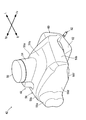
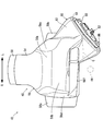
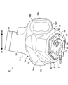
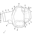
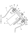
図2~図5を参照して、供給ユニット42は、燃料タンク48、蓋50および燃料ポンプ52を含む。燃料タンク48は、注入部54、本体部56、一対の取付部58a,58b、および燃料保持部60を含み、駆動源36に供給する燃料を保持する。注入部54は略円筒形状を有し、燃料タンク48の上部に設けられる。注入部54の上端部は、上方に向かって開口する。蓋50は、注入部54の上端部を塞ぐように注入部54に取り付けられる。作業者は、蓋50を取り外した状態で、注入部54の上端部から燃料タンク48に燃料を注入できる。
本体部56は中空略箱形状を有し、燃料タンク48の略中央部に設けられる。本体部56は、天井部56a、前壁部56b、後壁部56c、一対の側壁部56d,56e、および底部56fを有する。天井部56aは、注入部54の下端部から略水平方向に拡がるように設けられる。前壁部56bは、天井部56aの前端部から下方に延びる。後壁部56cは、天井部56aの後端部から下方に延びる。一対の側壁部56d,56eは、天井部56aの両側部から下方に延びる。この実施形態では、側壁部56dは、天井部56aの右端部から下方に延びかつ前壁部56bと後壁部56cとを連結する。側壁部56eは、天井部56aの左端部から下方に延びかつ前壁部56bと後壁部56cとを連結する。底部56fは、天井部56aに対向するように天井部56aの下方に設けられる。この実施形態では、底部56fは、前壁部56b、後壁部56c、側壁部56d,56eおよび燃料保持部60に接続されるように略水平方向に延びる。
図6を参照して、底部56fは、燃料保持部60側に向かって下に傾斜する傾斜面56gを有する。傾斜面56gは、燃料タンク48の内方に臨む面である。傾斜面56gは、燃料保持部60の内面60aに連続するように形成される。傾斜面56gと水平面とのなす角度A1は、たとえば、3度以上であることが好ましい。
図2~図5を参照して、一対の取付部58a,58bは中空形状を有し、一対の側壁部56d,56eから側方(左右方向)に突出する。この実施形態では、取付部58aは側壁部56dの後部から右方に突出し、取付部58bは側壁部56eの後部から左方に突出する。取付部58a,58bには、一対の支持部材34(図1参照)の上端部が固定される。これにより、燃料タンク48は一対の支持部材34(図1参照)を介してフレーム22(図1参照)に支持される。
図1および図3を参照して、ヘリコプタ10の幅方向において、燃料保持部60は、ドライブシャフト44からみて、テールロータ20とは反対側に設けられる。言い換えると、ヘリコプタ10の幅方向において、ドライブシャフト44からみて一方側に燃料保持部60が設けられ、他方側にテールロータ20が設けられる。この実施形態では、ドライブシャフト44の右側にテールロータ20が設けられ、ドライブシャフト44の左側に燃料保持部60が設けられる。
図2~図6を参照して、燃料保持部60は筒形状を有し、本体部56よりも下方に突出する。この実施形態では、燃料保持部60は、本体部56の左側から下方に突出する。より具体的には、燃料保持部60は、本体部56から左斜め下方に突出する。したがって、ヘリコプタ10が水平面上に着地している状態で、燃料保持部60の一部が燃料タンク48の最も下に位置している。
図3、図4、図6および図7を参照して、燃料保持部60は、周壁部62、底部64および蓋部材66を含む。
図3、図4、図6および図7を参照して、燃料保持部60は、周壁部62、底部64および蓋部材66を含む。
周壁部62は略角筒形状を有し、本体部56から下方(この実施形態では左斜め下方)に延びて、底部64の外縁に接続される。すなわち、周壁部62の端部に底部64が設けられる。この実施形態では、周壁部62は、本体部56側から底部64側に向かって拡がるように形成される。言い換えれば、燃料保持部60の内面60aは、本体部56側から底部64側に向かって拡がるように形成される。底部64は、略多角形状(この実施形態では略六角形状)の外縁を有する。底部64は、その中央部に開口部64aを有する環状部64b、および環状部64bから燃料保持部60内に凹む複数(この実施形態では6つ)の凹部64cを有する。凹部64cは、後述する複数(この実施形態では6つ)のねじ孔80c(図7参照)に対応して設けられる。蓋部材66は略円板状に形成され、蓋部材66の外径は開口部64aの内径より大きく設定される。
図6および図7を参照して、蓋部材66に燃料ポンプ52が取り付けられる。燃料ポンプ52は、蓋部材66の上面に設けられる略円板状の台座部68と、台座部68上に立設されるポンプ本体70と、ポンプ本体70の側方(この実施形態では右側)の下端部に設けられる吸入部72と、台座部68上に立設される略短冊状のフィルタ74と、ポンプ本体70に設けられる液面検出センサ76と、蓋部材66から下方に突出するように設けられる略L字状の吐出部78とを含む。
蓋部材66と台座部68とは互いに同心状に配置され、台座部68の外径は、開口部64aの内径と略等しく設定される。
フィルタ74は、吸入部72に接するように設けられる。吸入部72は、フィルタ74側の端面に、燃料保持部60内に臨むように設けられる燃料吸込口72aを有する。
吐出部78は、蓋部材66内および台座部68内を通ってポンプ本体70に連通している。ポンプ本体70は、図示しない動力発生装置(たとえば電動モータ)を含み、燃料タンク48内の燃料を、フィルタ74を介して吸入部72から吸入し、吐出部78から吐出する。ポンプ本体70の動力発生装置には、バッテリからの電力がコネクタ部(ともに図示せず)を介して供給される。これにより、ポンプ本体70が駆動される。
液面検出センサ76は、燃料吸込口72aと一体に設けられる液面検出部であり、燃料タンク48内の燃料の液面を検出する。
蓋部材66には、支持部材80が取り付けられる。支持部材80は、環状に形成される。支持部材80は、外縁が略六角形状かつ内縁が円形状に形成される。支持部材80は、外周部80aと、外周部80aの内縁から内方に形成される円環状のフランジ部80bと、外周部80aに形成される複数(この実施形態では6つ)のねじ孔80cとを有する。外周部80aの内径は、蓋部材66の外径と略等しく設定され、フランジ部80bの内径は、蓋部材66の外径より小さく設定される。支持部材80は、外周部80aが蓋部材66の外縁に接しかつフランジ部80bが蓋部材66の下面に接するように、蓋部材66に嵌められる。
このように燃料ポンプ52および支持部材80が取り付けられた蓋部材66が、燃料保持部60の開口部64aに設けられる。
このとき、燃料保持部60の底部64の各凹部64cに、袋ナット82が埋め込まれかつナット84が配置された状態で、開口部64aを囲むようにたとえばOリング等の封止部材86が配置される。その状態で、ポンプ本体70が底部64の開口部64aから燃料タンク48内に挿入され、支持部材80の各ねじ孔80cが凹部64cに対応するように位置決めされ、開口部64aに台座部68が嵌め込まれる。そして、複数(この実施形態では6つ)のたとえばボルトなどの締結部材88がそれぞれ、ねじ孔80cおよび封止部材86に挿通されて、ナット84および袋ナット82に取り付けられる。このようにして、燃料保持部60の底部64に蓋部材66が設けられる。したがって、燃料保持部60の底部64に、蓋部材66を介して燃料ポンプ52が取り付けられる。封止部材86によって、燃料タンク48内の燃料が燃料保持部60と燃料ポンプ52との間から漏れ出すことが防止される。
なお、吐出部78は、図示しない燃料ホースを介して、駆動源36に燃料を供給するための燃料噴射装置38に連結されている。燃料タンク48内の燃料は、燃料ポンプ52によって吐出され、燃料ホースを介して燃料噴射装置38に供給される。燃料噴射装置38は、燃料タンク48から供給された燃料を駆動源36内に噴射する。
図3から図7を参照して、このような供給ユニット42において、ヘリコプタ10が水平面上に着地している状態で、燃料ポンプ52の燃料吸込口72aに頂点が位置する仮想的な逆円錐Bを、逆円錐Bの母線B1と水平面とが所定の角度A2を有するように描いたとき、燃料保持部60と逆円錐Bの円錐面B2との交線Cは環状に形成される。図4および図5を参照して、図4に示す交線Cの両端D1,D2をそれぞれ、図5に示す交線Cの両端D1,D2に結べば、交線Cは環状になることは容易に理解できる。角度A2は、たとえば、10度以上であることが好ましく、15度以上であることがより好ましく、この実施形態では15度に設定される。
このようなヘリコプタ10によれば、燃料タンク48は、本体部56よりも少なくとも下方に突出する燃料保持部60を有することによって、本体部56よりも燃料保持部60に優先的に燃料を保持し易くなる。すなわち、本体部56内に燃料がないあるいは僅かな場合であっても、燃料保持部60内に燃料を確保し易くなる。したがって、燃料保持部60内の燃料を燃料吸込口72aから燃料ポンプ52に継続して取り込むことができるとともに飛行状態に拘わらず燃料ポンプ52が空気を吸い込むことを抑制できる。
燃料保持部60は筒状に形成されるので、加速または減速するためにヘリコプタ10を前後方向に傾けた状態をある程度の時間維持しながら飛行する際にも、燃料保持部60内に燃料を確保し易くなる。
燃料保持部60の周壁部62は本体部56側から底部64側に向かって拡がるように形成されるので、ヘリコプタ10を傾けても燃料を燃料保持部60内により確保し易くなる。
ドライブシャフト44からみて、燃料保持部60とテールロータ20とを反対側に設けることによって、ヘリコプタ10の重量バランスをとることができる。
燃料保持部60の一部が燃料タンク48の最も下に位置している。したがって、燃料タンク48内の燃料の残量が少ない際に、ヘリコプタ10が或る方向(たとえば左または右)に傾いた状態を維持しながら飛行しても、燃料が燃料保持部60内に留まっているため、空気を含まない燃料を燃料ポンプ52に供給できる。
燃料保持部60と円錐面B2との交線Cが環状に形成されるということは、燃料保持部60と円錐面B2とが全周に亘って交わることを意味する。言い換えれば、燃料保持部60は、円錐面B2よりも立ち上がっている(水平面に対する角度が大きい)部分を全周に亘って有することを意味する。したがって、ヘリコプタ10が任意の方向に所定の角度A2(たとえば15度)以下傾いた状態で飛行し続けたとしても、燃料の全てが燃料保持部60から流出することはなく、燃料保持部60内に保持された燃料を燃料吸込口72aから駆動源36に供給し続けることができる。
燃料ポンプ52のポンプ本体70は燃料タンク48内に設けられるので、燃料タンク48の周囲の部品点数を少なくできる。したがって、よりコンパクトなヘリコプタ10が得られる。
燃料保持部60は本体部56から外方かつ斜め下方に向かって延びる。したがって、燃料タンク48内に残る燃料が少ないときにヘリコプタ10が傾いた状態で飛行し続けても燃料を駆動源36に供給し続けるのに適切な位置に、燃料ポンプ52および燃料吸込口72aを配置できる。
燃料ポンプ52は蓋部材66に設けられ、燃料ポンプ52および蓋部材66を同時に着脱できるため、燃料ポンプ52および燃料タンク48のメンテナンスが容易になる。
ヘリコプタ10の飛行状態に拘わらず燃料ポンプ52が空気を吸い込むことを抑制できるため、駆動源36が燃料噴射装置38から燃料が供給されるエンジンであっても、エンジン空燃比の制御が安定した状態を維持できる。
本体部56の底部56fは、燃料保持部60側に向かって下に傾斜するように形成されるので、本体部56内の燃料が燃料保持部60に向かって流れ、燃料保持部60内に燃料が溜まり易くなる。
液面検出センサ76は燃料吸込口72aと一体に設けられるので、燃料吸込口72a周辺における燃料の残量を正確に検出できる。さらに、液面検出センサ76を取り付けるための部材を別途必要としないので、よりコンパクトで軽量なヘリコプタ10が得られる。
また、フィルタ74内においても燃料を保持できるので、燃料を燃料ポンプ52から駆動源36により確実に供給し続けることができる。
上述の実施形態では、燃料保持部60が本体部56の左側から下方に突出する場合について説明したが、燃料保持部は本体部の右側から下方に突出してもよい。より具体的には、燃料保持部は本体部から右斜め下方に突出してもよい。また、燃料保持部の形状は、筒形状に限定されず、たとえば球状や錐状であってもよい。
上述の実施形態では、1つの燃料保持部60が本体部56に設けられる場合について説明したが、燃料保持部の数は上述の例に限定されない。たとえば、本体部の右側および左側にそれぞれ燃料保持部が設けられてもよい。
上述の実施形態では、燃料ポンプ52のポンプ本体70は、燃料タンク48内に設けられる場合について説明したが、これに限定されず、燃料タンク48の外に設けられてもよい。
上述の実施形態では、駆動源36に燃料を供給する手段として、燃料噴射装置38を用いた場合について説明したが、これに限定されず、キャブレタを用いてもよい。
上述の実施形態では、駆動源36としてエンジンを用いた場合について説明したが、駆動源はエンジンに限定されない。たとえば、駆動源としてモータおよび燃料電池を用いてもよい。この場合、燃料タンク48には、燃料電池に供給される燃料が貯留される。
以上、この発明の好ましい実施形態について説明されたが、この発明の範囲および精神を逸脱しない限りにおいて種々の変更が可能であることは明らかである。この発明の範囲は、添付された請求の範囲のみによって限定される。
10 無人ヘリコプタ
20 テールロータ
36 駆動源
38 燃料噴射装置
44 ドライブシャフト
48 燃料タンク
52 燃料ポンプ
56 本体部
56f,64 底部
60 燃料保持部
62 周壁部
64a 開口部
66 蓋部材
70 ポンプ本体
72a 燃料吸込口
76 液面検出センサ
A1,A2 角度
B 仮想的な逆円錐
B1 母線
B2 円錐面
C 交線
20 テールロータ
36 駆動源
38 燃料噴射装置
44 ドライブシャフト
48 燃料タンク
52 燃料ポンプ
56 本体部
56f,64 底部
60 燃料保持部
62 周壁部
64a 開口部
66 蓋部材
70 ポンプ本体
72a 燃料吸込口
76 液面検出センサ
A1,A2 角度
B 仮想的な逆円錐
B1 母線
B2 円錐面
C 交線
Claims (12)
- 駆動源と、
本体部および前記本体部よりも少なくとも下方に突出するように前記本体部に設けられる燃料保持部を含み、前記駆動源に供給する燃料を保持する燃料タンクと、
前記燃料保持部内に臨むように設けられる燃料吸込口を有する燃料ポンプとを備え、
前記燃料保持部は、前記本体部の左側または右側のいずれか一方から下方に突出する、無人ヘリコプタ。 - 前記燃料保持部は筒状に形成される、請求項1に記載の無人ヘリコプタ。
- 前記燃料保持部は、前記本体部から延びる周壁部と、前記周壁部の端部に設けられる底部とを含み、前記周壁部は、前記本体部側から前記底部側に向かって拡がるように形成される、請求項1または2に記載の無人ヘリコプタ。
- テールロータと、
前記駆動源からの駆動力を前記テールロータに与えるためのドライブシャフトとをさらに備え、
前記ドライブシャフトは前後方向に延び、
前記ドライブシャフトからみて、前記燃料保持部は、前記テールロータとは反対側に設けられる、請求項1から3のいずれかに記載の無人ヘリコプタ。 - 当該無人ヘリコプタが水平面上に着地している状態で、前記燃料保持部の一部が前記燃料タンクの最も下に位置している、請求項1から4のいずれかに記載の無人ヘリコプタ。
- 当該無人ヘリコプタが水平面上に着地している状態で、前記燃料ポンプの前記燃料吸込口に頂点が位置する仮想的な逆円錐を、前記逆円錐の母線と前記水平面とが所定の角度を有するように描いたとき、前記燃料保持部と前記逆円錐の円錐面との交線は環状に形成される、請求項1から5のいずれかに記載の無人ヘリコプタ。
- 前記燃料ポンプは、前記燃料タンク内に設けられるポンプ本体を含む、請求項1から6のいずれかに記載の無人ヘリコプタ。
- 前記燃料保持部は前記本体部から左右方向の外側に向かって延びる、請求項2から7のいずれかに記載の無人ヘリコプタ。
- 前記燃料保持部は、開口部と、前記開口部に設けられる蓋部材とをさらに含み、
前記燃料ポンプは前記蓋部材に設けられる、請求項1から8のいずれかに記載の無人ヘリコプタ。 - 前記駆動源がエンジンであり、前記エンジンに燃料を供給する燃料噴射装置をさらに備える、請求項1から9のいずれかに記載の無人ヘリコプタ。
- 前記本体部の底部は、前記燃料保持部側に向かって下に傾斜するように形成される、請求項1から10のいずれかに記載の無人ヘリコプタ。
- 前記燃料タンク内の燃料の液面を検出するために前記燃料吸込口と一体に設けられる液面検出部をさらに備える、請求項1から11のいずれかに記載の無人ヘリコプタ。
Applications Claiming Priority (2)
| Application Number | Priority Date | Filing Date | Title |
|---|---|---|---|
| JP2013-137407 | 2013-06-28 | ||
| JP2013137407A JP2015009707A (ja) | 2013-06-28 | 2013-06-28 | 無人ヘリコプタ |
Publications (1)
| Publication Number | Publication Date |
|---|---|
| WO2014208680A1 true WO2014208680A1 (ja) | 2014-12-31 |
Family
ID=52142006
Family Applications (1)
| Application Number | Title | Priority Date | Filing Date |
|---|---|---|---|
| PCT/JP2014/067029 Ceased WO2014208680A1 (ja) | 2013-06-28 | 2014-06-26 | 無人ヘリコプタ |
Country Status (2)
| Country | Link |
|---|---|
| JP (1) | JP2015009707A (ja) |
| WO (1) | WO2014208680A1 (ja) |
Families Citing this family (2)
| Publication number | Priority date | Publication date | Assignee | Title |
|---|---|---|---|---|
| JP2019059815A (ja) * | 2017-09-25 | 2019-04-18 | 第一工業製薬株式会社 | 共重合体、分散剤、分散体組成物 |
| CN112407230A (zh) * | 2020-10-30 | 2021-02-26 | 中国直升机设计研究所 | 一种无人直升机多功能蒙皮结构 |
Citations (11)
| Publication number | Priority date | Publication date | Assignee | Title |
|---|---|---|---|---|
| GB573307A (en) * | 1940-09-20 | 1945-11-15 | Bernard Wilkinson | Improvements in or relating to fuel tanks for aircraft |
| GB851428A (en) * | 1957-08-28 | 1960-10-19 | United Aircraft Corp | Fuel supply system for use in aircraft |
| US4624425A (en) * | 1984-05-23 | 1986-11-25 | Michael Austin | Fixed wing light aircraft |
| JPH0228075A (ja) * | 1988-07-15 | 1990-01-30 | Yamaha Motor Co Ltd | 自動二輪車の燃料タンク装置 |
| JPH09110000A (ja) * | 1995-10-19 | 1997-04-28 | Yanmar Agricult Equip Co Ltd | 遠隔操縦ヘリコプタ |
| JPH09507445A (ja) * | 1993-12-20 | 1997-07-29 | ユナイテッド テクノロジーズ コーポレーイション | 燃料セルの除去方法 |
| US20050178916A1 (en) * | 2004-01-29 | 2005-08-18 | Howe Mark E. | Auxiliary fuel tank systems for aircraft and methods for their manufacture and use |
| JP2008238903A (ja) * | 2007-03-27 | 2008-10-09 | Honda Motor Co Ltd | 燃料タンク |
| JP2010116140A (ja) * | 2008-11-12 | 2010-05-27 | Honeywell Internatl Inc | 非袋状垂直燃料タンクを備えるダクトファン航空機 |
| US20130001364A1 (en) * | 2009-12-02 | 2013-01-03 | Saab Ab | Helicopter with removable fuel tank |
| US20130105628A1 (en) * | 2011-11-01 | 2013-05-02 | Vanguard Defense International, Llc | Airframe |
-
2013
- 2013-06-28 JP JP2013137407A patent/JP2015009707A/ja active Pending
-
2014
- 2014-06-26 WO PCT/JP2014/067029 patent/WO2014208680A1/ja not_active Ceased
Patent Citations (11)
| Publication number | Priority date | Publication date | Assignee | Title |
|---|---|---|---|---|
| GB573307A (en) * | 1940-09-20 | 1945-11-15 | Bernard Wilkinson | Improvements in or relating to fuel tanks for aircraft |
| GB851428A (en) * | 1957-08-28 | 1960-10-19 | United Aircraft Corp | Fuel supply system for use in aircraft |
| US4624425A (en) * | 1984-05-23 | 1986-11-25 | Michael Austin | Fixed wing light aircraft |
| JPH0228075A (ja) * | 1988-07-15 | 1990-01-30 | Yamaha Motor Co Ltd | 自動二輪車の燃料タンク装置 |
| JPH09507445A (ja) * | 1993-12-20 | 1997-07-29 | ユナイテッド テクノロジーズ コーポレーイション | 燃料セルの除去方法 |
| JPH09110000A (ja) * | 1995-10-19 | 1997-04-28 | Yanmar Agricult Equip Co Ltd | 遠隔操縦ヘリコプタ |
| US20050178916A1 (en) * | 2004-01-29 | 2005-08-18 | Howe Mark E. | Auxiliary fuel tank systems for aircraft and methods for their manufacture and use |
| JP2008238903A (ja) * | 2007-03-27 | 2008-10-09 | Honda Motor Co Ltd | 燃料タンク |
| JP2010116140A (ja) * | 2008-11-12 | 2010-05-27 | Honeywell Internatl Inc | 非袋状垂直燃料タンクを備えるダクトファン航空機 |
| US20130001364A1 (en) * | 2009-12-02 | 2013-01-03 | Saab Ab | Helicopter with removable fuel tank |
| US20130105628A1 (en) * | 2011-11-01 | 2013-05-02 | Vanguard Defense International, Llc | Airframe |
Also Published As
| Publication number | Publication date |
|---|---|
| JP2015009707A (ja) | 2015-01-19 |
Similar Documents
| Publication | Publication Date | Title |
|---|---|---|
| JP6463841B2 (ja) | 無人航空機 | |
| US11524797B2 (en) | Aircraft-retrieval system | |
| CN105752340B (zh) | 无人飞行器 | |
| CN206984368U (zh) | 运输无人机 | |
| JP6163041B2 (ja) | 燃料システム、航空機 | |
| JP5809422B2 (ja) | 無人ヘリコプター | |
| JP2017114186A (ja) | マルチコプタ | |
| CN108609165A (zh) | 无人机 | |
| CN103434643A (zh) | 一种六旋翼飞行器 | |
| CN104351157A (zh) | 一种无人机的农药喷洒装置 | |
| CN207060377U (zh) | 无人机 | |
| KR20150136641A (ko) | 농업용 무인방제 수직이착륙기 | |
| CN206485564U (zh) | 无人机 | |
| CN106428598B (zh) | 一种无人机云台和无人机 | |
| JPWO2019225607A1 (ja) | 飛行体および飛行体のフレーム | |
| JP2019069658A (ja) | 無人飛行体用フレーム | |
| JPH01237290A (ja) | 水噴射推進船 | |
| JP2015009707A (ja) | 無人ヘリコプタ | |
| WO2018171239A1 (zh) | 一种负压式低死油防气泡飞机油箱装置 | |
| WO2019181413A1 (ja) | 産業用ドローン | |
| CN205675214U (zh) | 一种快递无人机 | |
| CN103213683A (zh) | 一种油箱嵌入翼身融合体的小型多用途无人机 | |
| WO2016103485A1 (ja) | 培養フラスコ | |
| CN110834619B (zh) | 一种气垫船及其控制方法 | |
| JP2021169256A (ja) | ヘリコプタ |
Legal Events
| Date | Code | Title | Description |
|---|---|---|---|
| 121 | Ep: the epo has been informed by wipo that ep was designated in this application |
Ref document number: 14816590 Country of ref document: EP Kind code of ref document: A1 |
|
| NENP | Non-entry into the national phase |
Ref country code: DE |
|
| 122 | Ep: pct application non-entry in european phase |
Ref document number: 14816590 Country of ref document: EP Kind code of ref document: A1 |