WO2014208256A1 - カーテンエアバッグ装置 - Google Patents
カーテンエアバッグ装置 Download PDFInfo
- Publication number
- WO2014208256A1 WO2014208256A1 PCT/JP2014/064154 JP2014064154W WO2014208256A1 WO 2014208256 A1 WO2014208256 A1 WO 2014208256A1 JP 2014064154 W JP2014064154 W JP 2014064154W WO 2014208256 A1 WO2014208256 A1 WO 2014208256A1
- Authority
- WO
- WIPO (PCT)
- Prior art keywords
- vehicle
- expansion
- region
- curtain airbag
- gas
- Prior art date
- Legal status (The legal status is an assumption and is not a legal conclusion. Google has not performed a legal analysis and makes no representation as to the accuracy of the status listed.)
- Ceased
Links
Images


Classifications
-
- B—PERFORMING OPERATIONS; TRANSPORTING
- B60—VEHICLES IN GENERAL
- B60R—VEHICLES, VEHICLE FITTINGS, OR VEHICLE PARTS, NOT OTHERWISE PROVIDED FOR
- B60R21/00—Arrangements or fittings on vehicles for protecting or preventing injuries to occupants or pedestrians in case of accidents or other traffic risks
- B60R21/02—Occupant safety arrangements or fittings, e.g. crash pads
- B60R21/16—Inflatable occupant restraints or confinements designed to inflate upon impact or impending impact, e.g. air bags
- B60R21/23—Inflatable members
- B60R21/231—Inflatable members characterised by their shape, construction or spatial configuration
- B60R21/232—Curtain-type airbags deploying mainly in a vertical direction from their top edge
Definitions
- the present invention relates to a curtain airbag that inflates and deploys along a side surface in a vehicle compartment for the purpose of protecting an occupant during a vehicle side collision or rollover (rollover).
- the curtain airbag is an airbag that is installed above the side door in the vehicle interior and inflates and deploys along the side window of the vehicle when an impact occurs.
- the curtain airbag is large among various airbags, and an inflator (gas generator) to be equipped may require a large output.
- the shape of the inflator is large, and there is a tendency that a problem in layout tends to occur. Therefore, the curtain airbag is desired to have a configuration that can restrain an occupant with as little gas capacity as possible. For example, in the non-inflatable region provided in the curtain airbag of Patent Document 1, the occupant can be restrained without using gas.
- curtain airbags can use low-power, inexpensive, and small inflators as the gas capacity is reduced. However, even in that case, it is a premise that the occupant's outside-release prevention performance, which is the original function of the curtain airbag, is not deteriorated.
- the vehicle release prevention performance is highly evaluated as the amount of occupants released from the side window at the time of a side collision, that is, the vehicle release amount is smaller.
- the non-inflatable area of the curtain airbag of Patent Document 1 has the advantage of reducing the gas capacity, it may affect the anti-release performance of the curtain airbag when installed easily. Consideration is necessary.
- the present invention has been made in view of such a problem, and an object of the present invention is to provide a curtain airbag capable of exhibiting high out-of-vehicle release prevention performance while suppressing gas capacity.
- a typical configuration of a curtain airbag according to the present invention is a curtain airbag that is stored above a side surface in a vehicle compartment and inflates and deploys along the side surface, and gas flows into the curtain airbag.
- An inflatable bag-like inflatable region and a non-inflatable region into which gas does not flow, and the inflatable region includes a duct portion extending in the vehicle front-rear direction at the upper part of the rear side window on the vehicle rear side of the center pillar of the side surface portion.
- a front inflating portion that is provided on the vehicle front side of the rear side window and expands in a predetermined range above and below the center pillar, a rear inflating portion that inflates on the rear side of the vehicle on the rear side window, and a vehicle lower side on the rear side window
- a lower connecting portion that extends in the vehicle longitudinal direction and communicates the lower end of the front inflating portion and the lower end of the rear inflating portion, and the non-inflating region includes a duct portion
- the rear side window is surrounded by the side connecting part, the front inflating part, and the rear inflating part, and the front edge of the rear inflating part is an opening area that is covered by the rear side window as a collision target of an impactor that is a test apparatus in the vehicle outside release prevention performance evaluation test Among a plurality of hitting positions each having a predetermined area, the second hitting point position second from the center pillar toward the vehicle rear side and the vehicle rear side from the hitting point center of the second hitting point position The upper edge
- the device in order to provide a non-inflatable region that does not require gas, the device has been devised so that the out-of-vehicle release prevention performance does not deteriorate.
- region is provided by making the 2nd hit point position into a standard among the several hit point positions of the impactor in a vehicle outside discharge
- the first hit point position is a position close to the center pillar, but the area near the center pillar of the curtain airbag is supported by the center pillar, so that the outside release prevention performance is originally high.
- expansion regions are provided in the main portion of the second hit point position, particularly in the vehicle rear side and the vehicle lower side. If it is an inflating region, it protrudes to the inside of the vehicle as compared with the non-inflating region, so that the occupant can be restrained at an early stage and the amount of release outside the vehicle can be suppressed.
- a non-inflatable region is provided on the vehicle front side above the second hit point position.
- the above-described non-expanded region may overlap with a first hit point position that is first located from the center pillar toward the vehicle rear side among a plurality of hit point positions. Since the non-inflatable region does not expand, the non-inflatable region is located on the vehicle outer side compared to the vehicle inner surface of each inflated region, which may be disadvantageous in terms of suppressing the amount of occupant discharge from the vehicle. However, since the area on the curtain airbag that overlaps the first hit point position is close to the area that is supported by the center pillar, the amount of discharge outside the vehicle is originally small. Therefore, by setting the region overlapping the first hit point position as the non-expanded region as described above, it is possible to reduce the gas capacity without deteriorating the vehicle release prevention performance.
- the curtain airbag device includes an inflator that supplies gas to an inflatable region, an inflator attachment portion that guides gas from the inflator to a duct portion by attaching the inflator at a predetermined position above the duct portion, and gas received from the duct portion.
- a front main chamber that expands on the front side of the vehicle relative to the front expansion portion; and a rear main chamber that receives gas from the duct portion and expands on the rear side of the vehicle relative to the rear expansion portion. It is preferable that the gas flows from the rear main chamber by receiving gas from the rear main chamber, and the rear expansion portion expands after receiving the gas from the rear main chamber.
- the front expansion portion and the rear expansion portion are realized as regions (delay chambers) that subsequently expand after each main chamber.
- the expansion of the front expansion portion and the rear expansion portion is completed slightly later (several milliseconds to several tens of milliseconds) than the main chamber, it can be adjusted in accordance with the rollover that occurs following the side collision. Inflated. Therefore, the non-inflatable region can also be tensioned at the time of rollover and exhibit its occupant restraint performance.
- the curtain airbag device further includes a front communication port that connects the front inflating portion and the front main chamber, and the vertical width of the front communication port is preferably shorter than the vertical length of the front inflating portion. That is, the front expansion part is not connected to the front main chamber in the entire upper and lower parts, but is connected to the front main chamber through a front connection port that is smaller in the vertical direction than the front expansion part.
- the front communication port having this configuration, the amount of gas supplied per unit time from the front main chamber to the front expansion section can be limited, and the expansion and deployment of the front expansion section can be completed in accordance with the rollover.
- the curtain airbag device further includes a rear communication port that connects the rear inflating portion and the rear main chamber, and the vertical width of the rear communication port is preferably shorter than the vertical length of the rear inflating portion.
- the rear expansion part is not connected to the rear main chamber in the entire upper and lower parts, but is connected to the rear main chamber through a rear connection port that is smaller in the vertical direction than the rear expansion part.
- the front expansion part, the rear expansion part, and the lower communication part that connects them are preferably delay chambers that complete the expansion and deployment with a delay compared to other parts included in the expansion region.
- the front expansion part, the rear expansion part, and the lower connection part are slightly delayed (several milliseconds to several tens of milliseconds) from the other main chambers as a delay chamber. It will be in an expanded state according to the rollover. Accordingly, the non-inflatable region surrounded by the delay chamber and the duct portion can also be tensioned at the time of rollover and exhibit its occupant restraint performance.
- the present invention it is possible to provide a curtain airbag capable of exhibiting high out-of-vehicle release prevention performance while suppressing gas capacity.
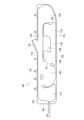
- FIG. 2 is an enlarged detail view of the curtain airbag of FIG. It is the figure which illustrated the non-expansion area
- FIG. 1 is a diagram illustrating a curtain airbag 100 as an embodiment of the curtain airbag device of the present invention.
- FIG. 1A is a view of the interior of the vehicle as viewed from the vehicle inner side in the vehicle width direction, and illustrates a storage form of the cushion portion 102 of the curtain airbag 100.
- the cushion portion 102 is a portion that is inflated and deployed in an emergency to protect the occupant.
- FIG. 1B illustrates the time when the cushion portion 102 is inflated and deployed.
- the expression “up” indicates the vehicle ceiling direction as viewed from the point of interest
- the expression “down” indicates the vehicle floor direction as viewed from the point of interest.
- the cushion portion 102 is wound and becomes a roll-shaped storage form that is long in the front and rear of the vehicle, and is attached to the upper side portion (the roof side rail 104) in the vehicle interior. Installed. Normally, since the roof side rail 104 is covered with a roof trim (not shown), the installed cushion portion 102 is not visible from the vehicle interior.
- the storage form of the cushion part 102 can also be realized by folding.
- the curtain airbag 100 includes an inflator 106, which is a gas generator, on the upper portion of the cushion portion 102.
- the cushion portion 102 is inflated by the pressure of gas supplied from the inflator 106 to restrain the occupant.
- the inflator 106 employed in this embodiment is a cylinder type (tubular type).
- Inflators that are currently popular are types that are filled with a gas generating agent and burn it to generate gas, types that are filled with compressed gas and supply gas without generating heat, and There are types including both a gas generating agent and a compressed gas. Any type of inflator 106 can be used.
- a sensor (not shown) provided in the vehicle 108 first detects an impact and transmits an ignition signal to the inflator 106. Then, the explosive of the inflator 106 burns and the generated gas is supplied to the cushion part 102. When the gas from the inflator 106 is received, the cushion portion 102 expands downward along the side surface portions (the front side window 110 and the rear side window 112) of the passenger compartment as illustrated in FIG. Expands and protects passengers.
- FIG. 2 is a diagram exemplarily showing the cushion portion 102 when deployed in FIG. 1 (b).
- the cushion part 102 illustrated in FIG. 2 is manufactured, for example, by sewing a base fabric that constitutes the surface thereof on the front and back sides or by using OPW (One-Piece Woven).
- the cushion portion 102 is roughly configured to include an inflated region formed in a bag shape so that gas flows in and a non-inflated region 136 formed in a cloth shape into which gas does not flow.
- An inflator attachment portion 116 is provided near the center of the upper edge 114 of the cushion portion 102.
- the inflator attachment portion 116 serves as an attachment port for attaching the inflator 106 (see FIG. 1B), and guides the gas from the inflator 106 to the duct portion 118 therebelow.
- the duct portion 118 is a gas passage extending in the vehicle front-rear direction at the upper portion of the rear side window 112 of FIG. 1A, and the gas received from the upper inflator attachment portion 116 is passed to each portion in the vehicle front-rear direction. And flow.
- the duct portion 118 is disposed along the upper edge 114 of the cushion portion 102 and extends from the front end of the chamber 137 in front of the vehicle to the rear end of the rear main chamber 124.
- the expansion region of the cushion portion 102 is partitioned into a plurality of small rooms (chambers).
- a front main chamber 120 is provided on the vehicle front side of the duct portion 118.
- the front main chamber 120 is inflated and deployed by receiving gas from the duct portion 118, and mainly protects the occupant of the front seat 122 of FIG.
- a rear main chamber 124 is provided behind the duct portion 118 in the vehicle.
- the rear main chamber 124 also receives gas from the duct portion 118 and expands and deploys to protect the occupant of the rear seat 126.
- a front delay chamber 128 is provided on the vehicle rear side of the front main chamber 120 and the vehicle lower side of the duct portion 118 as a front expansion portion that can be placed in this embodiment.
- the front delay chamber 128 receives the gas through the front main chamber 120 on the front side of the vehicle, and completes the expansion and deployment slightly behind the front main chamber 120.
- the front delay chamber 128 expands by overlapping a predetermined range above and below the center pillar 130 (the pillar in which the front side window 110 is present on the front side of the vehicle and the rear side window 112 is present on the rear side of the vehicle) in FIG.
- the front delay chamber 128 which is the front expansion portion and the front main chamber 120 are communicated with each other through a front communication port 131.
- the front communication port 131 is a gas passage and is provided in the vicinity of the center of the front delay chamber 128 on the front side of the vehicle.
- the vertical width of the front communication port 131 is set shorter than the vertical length of the front delay chamber 128.
- the front delay chamber 128 is not connected to the front main chamber 120 in the entire vertical direction, but is connected to the front main chamber 120 through the front communication port 131 that is smaller in the vertical direction than the front delay chamber 128.
- the front communication port 131 having this configuration allows the gas to flow into the front main chamber 120 in front of the front delay chamber 128 and restricts the amount of gas supplied to the front delay chamber 128 per unit time. Therefore, the expansion and deployment of the front delay chamber 128 is intentionally delayed. As a result, the expansion and deployment of the front delay chamber 128 can be completed in accordance with the rollover.
- a rear delay chamber 132 is provided on the vehicle front side of the rear main chamber 124 and the vehicle lower side of the duct portion 118 as a rear expansion portion that can be placed in this embodiment.
- the rear delay chamber 132 receives gas through the rear main chamber 124 at the rear of the vehicle, and the expansion and deployment of the rear delay chamber 132 are completed with a slight delay after the rear main chamber 124.
- the rear delay chamber 132 expands so as to overlap the rear part of the rear side window 112 in FIG.
- the rear delay chamber 132 and the rear main chamber 124, which are the rear expansion part, are communicated with each other through a rear communication port 135.
- the rear communication port 135 is a gas passage and is provided near the lower part of the rear delay chamber 132 on the rear side of the vehicle.
- the vertical width of the rear communication port 135 is also set shorter than the vertical length of the rear delay chamber 132. That is, the rear delay chamber 132 is not connected to the rear main chamber 124 in the entire top and bottom, but is connected to the rear main chamber 124 through the rear communication port 135 that is smaller in the vertical direction than the rear delay chamber 132.
- the rear communication port 135 of this configuration allows the gas to flow into the rear delay chamber 132 while being circulated into the rear main chamber 124, and limits the amount of gas supplied to the rear delay chamber 132 per unit time.
- the expansion and deployment of the rear delay chamber 132 is intentionally delayed.
- the expansion and deployment of the rear delay chamber 132 can be completed in accordance with the rollover.
- the rear part of the vehicle at the lower end 129 of the front delay chamber 128 and the front part of the vehicle at the lower end 133 of the rear delay chamber 132 are connected by a lower communication part 134.
- the lower communication portion 134 extends in the vehicle front-rear direction on the vehicle lower side on the rear side window 112 in FIG. 1B and communicates gas between the front delay chamber 128 and the rear delay chamber 132.
- the lower connecting portion 134 is also a delay chamber similar to the front delay chamber 128 and the like, and is a portion where expansion and deployment is completed later than other portions of the expansion region.
- the cushion portion 102 has a configuration in which each delay chamber is provided between the front main chamber 120 and the rear main chamber 124.
- the chamber 137 further ahead of the vehicle than the front main chamber 120 can also be set as a delay chamber that completes the expansion and deployment later than the other chambers.
- the chamber 137 implemented as a delay chamber, it is possible to efficiently restrain the occupant even in the vicinity of the front end of the side window at the time of rollover.
- the non-expanding region 136 is surrounded by the duct portion 118 and the lower connecting portion 134 in the vehicle vertical direction, and is surrounded by the front delay chamber 128 that is the front expansion portion and the rear delay chamber 132 that is the rear expansion portion in the vehicle front-rear direction.
- the rear side window 112 is covered. That is, the non-expanding region 136 is a portion surrounded by the duct portion 118 and each delay chamber.
- the non-inflatable region 136 is a cloth-like portion where gas does not flow in, the non-inflatable region 136 is pulled and tensioned from the duct portion 118 and the lower communication portion 134, the front delay chamber 128 and the rear delay chamber 132, and exerts occupant restraint force It is possible to do.
- the edge 142 and the like of the cushion portion 102 are also cloth-like portions that do not expand, but are distinguished from portions that are different from the non-inflatable region 136.
- the above-described front delay chamber 128, rear delay chamber 132, and lower connecting portion 134 that connects them are delay chambers that are inflated and deployed in a delayed manner as compared with other parts included in the expansion region.
- These front delay chambers 128 and the like are slightly delayed (several msec to several tens of msec) from the other main chambers and the like, so that the expansion and deployment are completed. Become. Therefore, the non-inflatable region 136 surrounded by the front delay chamber 128 and the like and the duct portion 118 can also be tensioned in accordance with the rollover and exhibit the occupant restraint performance.
- the curtain airbag 100 by providing a non-inflatable region, the gas capacity of the cushion portion 102 can be reduced, and the output required for the inflator 106 can be suppressed. Therefore, the curtain airbag 100 can accept the use of a low-cost, inexpensive and small inflator. Such a small inflator is preferable because the degree of freedom in layout on the roof side rail 104 in FIG.
- a plurality of tabs 138 are provided on the upper edge 114 of the cushion portion 102 as portions for attachment to the roof side rail 104 (see FIG. 1B).
- the tab 138 is formed in a band shape, and is fixed to the roof side rail 104 by using a bolt or the like.
- a strap 140 is provided at the front end of the vehicle.
- the strap 140 is a member that stabilizes the posture of the cushion portion 102 when inflated and deployed.
- the strap 140 connects the edge 142 and the front pillar 144. When the expansion region is expanded, the expansion region slightly contracts in the vehicle front-rear direction, and the strap 140 has a shape that is tensioned at that time.
- tension is applied to each chamber or the like at the time of expansion and deployment, and the posture is stabilized without breaking.
- the non-inflatable region of the curtain airbag 100 can exhibit high off-vehicle emission reduction performance while suppressing the output required for the inflator 106.
- the range and position where the non-inflatable region is provided are devised.
- a detailed configuration of the non-inflatable region will be described.
- FIG. 3 is an enlarged detail view of the curtain airbag 100 of FIG. Symbols A1 to A4, B2, B3, and B5 illustrated in FIG. 3 are impactors 150 (test equipment that simulates an occupant in a vehicle exterior release prevention performance evaluation test based on NPRM (NHTSA-2009-0183), see FIG. 4 (b). ).
- the out-of-vehicle emission prevention performance evaluation test is a test defined in NPRM (NHTSA-2009-0183).
- the impactor 150 is the same as that of NPRM (NHTSA-2009-0183). It is defined in “Proposed Ejection Mitigation Requirements and Test Procedures”.
- the impact target of the impactor 150 is the same as that of NPRM (NHTSA-2009-0183). “Proposed Ejection Mitigation Requirements and Test Procedures”, d. “Locations Where the Device would Impact the Ejection Mitigation Countermeasure To Asses Efficacy”, 4.Targets defined by “Method for Determining Impactor Target LocationsTarget” ing.
- These hit points are exemplified by the hit point positions of the targets described in the NPRM, for example, the points shown in A1 to A4, B2, B3, and the like.
- Each hitting point is set with respect to the opening regions 144a and 144b (lighting openings) covered by the front side window 110 and the rear side window 112, respectively, and the cushion portion 102 is designed so as to cover these hitting points.
- the definition of the daylighting opening is that the opening of the side window (including the portion of the window glass in the 50 mm car) is directed to the center plane in the vehicle longitudinal direction (vertical plane obtained by cutting the center of the vehicle in the longitudinal direction). It is said that it is the range projected horizontally.
- Each spot position such as the spot position A1 has a predetermined area according to the shape of the impactor 150 (see FIG. 4B, etc.), and is set at various positions of the daylighting opening.
- the outline of the setting procedure is as follows. First, offset lines F1 and F2 (lines in which the outer edge of the daylighting opening is moved 25 ⁇ 2 mm toward the center) are set in the daylighting opening. Then, the outline of the impactor 150 (the outline of the headform of the impactor 150) is arranged at a position where the outline contacts the offset lines F1 and F2 (within 2 mm) at a predetermined point, and this is determined as the hitting position.
- a main target position (in this embodiment, hitting point positions A1 and A4 and B3 and B2 are equal) is determined.
- a vertical line and a horizontal line passing through the center of the daylighting opening are drawn to divide the daylighting opening into four sections.
- the front lower section and the rear upper section are the main quadrant sections.
- the front upper section and the rear lower section are main quadrant sections.
- those arranged such that the offset line of the impactor 150 is in contact at two or three points are the main target positions (the hit point positions A1, A4, B3, B2).
- a secondary target position (for example, hit point positions A3 and A2 are equal) is determined.
- two vertical lines are drawn inside the daylighting opening so as to divide the two previously determined main target positions (for example, hit point positions A1 and A4) into three equal parts.
- the outline of the impactor 150 is centered on this vertical line, and in the lower section of the four sections described above, the lower portion of the outline is in contact with the offset line, or in the upper section, the outline is aligned with the offset line. Arrange so that the top of These are the secondary target positions (spot positions A2 and A3).
- the method for determining the secondary target position is different.
- the window frame is small as described above and there is a distance of 360 mm or more between the hit point positions B3 and B2 that have already been determined, on the straight line connecting the hit point centers of these hit point positions B3 and B2.
- the intermediate point is determined as a secondary target position (for example, hitting point position B5).
- the amount of movement of the impactor 150 in the vehicle outward direction is measured during the side collision test based on NPRM.
- the measurement standard of the movement amount at that time is a vertical surface that is in contact with the outermost surface of the impactor 150 when the impactor is in contact with the inner surface of each side window.
- the non-expanding region 136 overlaps with a hitting point position B3 that is a first hitting point position first from the center pillar 130 toward the vehicle rear side in the opening region 144a covered by the rear side window 112. Is provided. Since the non-inflatable region 136 does not expand, it is located on the vehicle outer side compared to the vehicle inner surface of each expansion region, which may be disadvantageous in terms of suppressing the amount of occupant discharge outside the vehicle. However, since the region on the curtain airbag 100 that overlaps the hit point position B3 is close to the region that is supported by the center pillar 130, the performance of preventing release from the vehicle is originally high. Therefore, by setting the region overlapping with the hit point position B3 as described above as the non-inflatable region 136, it is possible to reduce the gas capacity without reducing the out-of-vehicle release prevention performance.
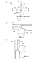
- FIG. 4 is a diagram illustrating the vicinity of the non-expanded region in FIG. 3 from each direction.
- FIG. 4A is an enlarged view near the hit point position B5 in FIG.
- the hit point position B5 illustrated in FIG. 4A is a second hit point position located second from the center pillar 130 (see FIG. 3) toward the vehicle rear side.
- the boundary between the rear end of the non-expanding region 136 and the expanding region (the rear delay chamber 132 and the lower connecting portion 134) is set on the hit point position B5.
- the front edge 146 of the rear delay chamber 132 is located in the vehicle rear side region relative to the hit point center P on the hit point position B5, and the upper edge 148 of the lower connecting portion 134 is the hit point center on the hit point position B5. It is set to be located in a region below the vehicle from P.
- the front edge 146 of the rear delay chamber 132 is a joining line that mainly borders the rear delay chamber 132 and extends in the vehicle vertical direction. This leading edge 146 also constitutes the rear end of the non-inflatable region 136.
- the upper edge 148 of the lower connecting portion 134 is a joining line that mainly borders the lower connecting portion 134 and extends in the vehicle front-rear direction, and also constitutes the lower end of the non-inflatable region 136.
- the front edge 146 of the rear delay chamber 132 and the upper edge 148 of the lower connecting portion 134 are continuous while being curved to some extent and do not need to be clearly distinguished.
- the front edge 146 is roughly referred to as a location including a portion that can have a tangent in the vehicle vertical direction
- the upper edge 148 is referred to as a location including a portion that can have a tangent in the vehicle horizontal direction.
- the upper edge 148 of the lower connecting portion 134 enters from the front side of the vehicle at a position below the hit point center P with respect to the hit point position B5. It extends like so.
- the front edge 146 of the rear delay chamber 132 enters at least the hit position B5 of the upper edge 148 from the position below the hit point center P continuing from the upper edge 148 of the lower connecting portion 134 and the rear side of the vehicle. It extends toward the upper side of the vehicle so as to exit from above.
- FIG. 4B is a cross-sectional view taken along the line AA in FIG. As illustrated in FIG. 4B, in this embodiment, when the impactor 150 is brought into contact with the hit point position B ⁇ b> 5, the rear half of the impactor 150 is restrained by the rear delay chamber 132.
- 4C is a cross-sectional view taken along the line BB in FIG. 4A. The lower half of the impactor 150 is restrained by the lower connecting portion 134.
- FIG. As described above, the impactor 150 is in contact with the rear delay chamber 132 and the lower connecting portion 134 that protrude to the outside of the vehicle, and is less likely to touch the non-inflatable region 136 that is located on the outside of the vehicle.
- the main portion of the hit point position B5, particularly the vehicle rear side and the vehicle lower side, are provided with the expansion regions (the rear delay chamber 132 and the lower connecting portion 134).
- the impactor 150 heading for B5 is contacted and restrained at an early stage, and the amount of discharge outside the vehicle can be suppressed.
- a non-inflatable region is provided on the vehicle front side above the hit point position B5, the configuration contributes to a reduction in gas capacity.
- the front delay chamber 128 and the rear delay chamber 132 are expanded and deployed slightly later (several milliseconds to several tens of milliseconds) than the main chambers. It will be in an expanded state according to the rollover. Accordingly, the non-inflatable region 136 is also tensioned at the time of rollover, and can exhibit its occupant restraint performance.
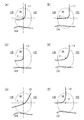
- FIG. 5 is a modification of the non-expanded region 136 in FIG.
- the boundaries between the non-inflatable region 136, the rear delay chamber 132, and the lower connecting portion 134 are denoted by symbols L1 to L6.
- the boundary L1 extends from the upper part on the vehicle rear side of the hit point center P to the front part on the vehicle lower side of the hit point center P so as to pass through the hit point center P on the hit point position B5.
- 5B is set so that the upper edge of the lower connecting portion 134 extends linearly from the hit point center P toward the vehicle front side.
- the front edge of the rear delay chamber 132 is linearly provided from the hit point center P along the vehicle upper direction.
- the boundary L4 in FIG. 5 (d) has a relatively large arc
- the boundary L5 in FIG. 5 (e) has a small angle of bending in the middle and extends obliquely as a whole.
- the non-inflatable region 136 does not reach the hitting point center P, but the boundary L6 is the same as the hitting point center P and the portion located on the vehicle rear side to the same extent as the hitting point center P. From the vehicle lower side to the vehicle upper side and the vehicle front side. Even in the non-expanded region 136 having these shapes, the delay chamber 132 and the lower communication portion 134 that are inflated regions are in contact with most of the impactor 150 (see FIG. 4) at the hit point position B5. The amount can be reduced.
- the present invention can be used for a curtain airbag that inflates and deploys along a side surface of a vehicle interior for the purpose of protecting an occupant at the time of a vehicle side collision or rollover (rollover).
Landscapes
- Engineering & Computer Science (AREA)
- Mechanical Engineering (AREA)
- Air Bags (AREA)
Abstract
【課題】ガス容量を抑えつつも高い車外放出防止性能を発揮可能なカーテンエアバッグ。 【解決手段】カーテンエアバッグ100は、各膨張領域と非膨張領域136とを備える。膨張領域はダクト部118、センタピラー130に重なるフロントディレーチャンバ128、リアディレーチャンバ132、下側連絡部134を含む。非膨張領域136は、ダクト部118および下側連絡部134、フロントディレーチャンバ128およびリアディレーチャンバ132に囲まれてリアサイドウィンドウ112を覆う。リアディレーチャンバ132の前縁146は、車外放出防止性能評価試験におけるインパクタ150の打点位置B5の打点中心Pから車両後方側の領域に位置し、リアディレーチャンバ132の前縁146から連続する下側連絡部134の上縁148は、打点位置B5上であって打点中心Pから車両下方側の領域に位置する。
Description
本発明は、車両の側面衝突時やロールオーバ(横転)時に、乗員保護を目的として車両室内の側面部に沿って膨張展開するカーテンエアバッグに関するものである。
近年、車両には高い安全性が求められている。この傾向は世界各国に共通していて、現在では世界各国でエアバッグが車両の安全装置としてほぼ標準装備されている。そして、車両開発に関係する事業者はさらなる安全性向上を重要な開発テーマとして掲げ、これに伴って日々新たなエアバッグを開発している。
車両の安全性の評価基準は各国において異なっていて、各事業者は製造品が多国の評価基準に対応し得るよう開発を行っている。例えば世界最大の自動車保有台数をほこる米国では、米国高速道路交通安全局(NHTSA)によって米国連邦自動車安全基準(FMVSS)が制定されている。このNHTSAによって正式に制定されたFMVSS226の基となっているFMVSSの規則策定の通知(NPRM;Notice of Proposed Rule Making: docket Number NHTSA-2009-0183)には「側突時・ロールオーバ(横転)時において、放出緩和システムによりサイドウィンドウを通した乗員の車外放出の見込みを減少させる」という要件が提案されている。この要件は、放出緩和システムを成す車外放出軽減対策装置としてカーテンエアバッグを備えることで達成可能である。
カーテンエアバッグは、車室内のサイドドアの上方に設置されていて、衝撃発生時に車両のサイドウィンドウに沿って膨張展開するエアバッグである。カーテンエアバッグは各種エアバッグの中でも大型であり、装備させるインフレータ(ガス発生装置)も出力の大きなものが必要になることがある。しかし、インフレータは出力の大きいものほど高価であり、さらには形状も大型になってレイアウト上の問題が生じやすくなる傾向がある。そのため、カーテンエアバッグはなるべく無駄のないガス容量で乗員を拘束できる構成が望まれている。例えば、特許文献1のカーテンエアバッグが備えている非膨張領域であれば、ガスを利用しなくとも乗員を拘束することができる。
カーテンエアバッグは、ガス容量を抑えた構成であるほど、低出力で安価かつ小型のインフレータを使用することが可能になる。しかしその場合であっても、カーテンエアバッグの本来の機能である乗員の車外放出防止性能を低下させないことが前提である。車外放出防止性能は、側突時に乗員がサイドウィンドウから放出される量、すなわち車外放出量が少ないほど高く評価される。特許文献1のカーテンエアバッグが備える非膨張領域は、ガス容量を抑えるという利点はあるものの、安易に設置するとカーテンエアバッグの車外放出防止性能に影響を与えるおそれがあり、設置するには相応の配慮が必要である。
本発明は、このような課題に鑑み、ガス容量を抑えつつも高い車外放出防止性能を発揮可能なカーテンエアバッグを提供することを目的としている。
上記課題を解決するために、本発明にかかるカーテンエアバッグの代表的な構成は、車両室内の側面部上方に収納され、側面部に沿って膨張展開するカーテンエアバッグであって、ガスが流入して膨張する袋状の膨張領域と、ガスの流入しない非膨張領域とを備え、膨張領域は、側面部のセンタピラーの車両後方側におけるリアサイドウィンドウの上部にて車両前後方向に延びるダクト部と、リアサイドウィンドウの車両前方側に設けられ、センタピラーの上下の所定範囲に重なって膨張する前方膨張部と、リアサイドウィンドウ上の車両後方側で膨張する後方膨張部と、リアサイドウィンドウ上の車両下方側にて車両前後方向に延び、前方膨張部の下端と後方膨張部の下端とを連絡する下側連絡部と、を含み、非膨張領域は、ダクト部、下側連絡部、前方膨張部および後方膨張部によって囲まれてリアサイドウィンドウを覆い、後方膨張部の前縁は、車外放出防止性能評価試験における試験装置であるインパクタの衝突目標としてリアサイドウィンドウが覆う開口領域内に設定されるそれぞれ所定面積を有する複数の打点位置のうち、センタピラーから車両後方側へ向かって2番目に位置する第2打点位置上であって第2打点位置の打点中心から車両後方側の領域に位置し、後方膨張部の前縁から連続する下側連絡部の上縁は、第2打点位置上であって打点中心から車両下方側の領域に位置することを特徴とする。
上記構成では、ガスの必要のない非膨張領域を設けるにあたり、車外放出防止性能が低下しないよう工夫を凝らしている。まず上記構成では、車外放出防止性能評価試験におけるインパクタの複数の打点位置のうち、第2打点位置を目安にして非膨張領域を設けている。例えば、車外放出防止性能評価試験における第1打点位置はセンタピラーに近い位置であるが、カーテンエアバッグのセンタピラー付近の領域はセンタピラーに支えられることで車外放出防止性能が元々高い。しかし、第1打点位置よりも車両後方側に位置する第2打点位置では、センタピラー等の支えになる部位から遠いため、カーテンエアバッグの車外放出防止性能は低下し、乗員の車外放出量が増加しがちである。そこで上記構成では、第2打点位置の主要部分、特に車両後方側と車両下方側とには膨張領域(後方膨張部および下側連絡部)を設けている。膨張領域であれば、非膨張領域に比べて車内側に突出しているため、乗員を早期に拘束してその車外放出量を抑えることができる。そして、第2打点位置の上部の車両前方側には非膨張領域を設けている。この構成であれば、ガス容量を削減しつつ、車外放出防止性能を高く維持することが可能である。
上記の非膨張領域は、複数の打点位置のうち、センタピラーから車両後方側へ向かって1番目に位置する第1打点位置に重なるとよい。非膨張領域は膨張しないため、各膨張領域の車内側表面に比べて車外側に位置していて、乗員の車外放出量を抑えるという点においては不利になりかねない。しかし第1打点位置に重なるカーテンエアバッグ上の領域は、センタピラーに重なって支えられる領域に近接しているため、車外放出量が元々少ない。したがって、上記のように第1打点位置に重なる領域を非膨張領域とすることで、車外放出防止性能を下げることなく、ガス容量を削減することが可能になる。
当該カーテンエアバッグ装置は、膨張領域にガスを供給するインフレータと、ダクト部の上部の所定位置にインフレータを取り付けてダクト部へインフレータからのガスを導くインフレータ取付部と、ダクト部からガスを受けて前方膨張部よりも車両前方側で膨張するフロントメインチャンバと、ダクト部からガスを受けて後方膨張部よりも車両後方側で膨張するリアメインチャンバと、をさらに備え、前方膨張部はフロントメインチャンバからガスを受けることでフロントメインチャンバに続いて膨張し、後方膨張部はリアメインチャンバからガスを受けることでリアメインチャンバに続いて膨張するとよい。
上記構成では、前方膨張部および後方膨張部は、各メインチャンバに続いてその後に膨張する領域(ディレーチャンバ)として実現されている。この構成によれば、前方膨張部および後方膨張部は、メインチャンバに比べて若干遅く(数msec~数十msec)に膨張展開が完了するため、側面衝突に続いて発生するロールオーバ時に合わせて膨張状態となる。したがって、非膨張領域もまたロールオーバ時に合わせて緊張してその乗員拘束性能を発揮することが可能になる。
当該カーテンエアバッグ装置はさらに、前方膨張部とフロントメインチャンバとを連絡する前方連絡口を有し、前方連絡口の上下幅は、前方膨張部の上下長さよりも短いとよい。すなわち前方膨張部は、上下全体でフロントメインチャンバとつながっているのではなく、前方膨張部よりも上下に小さい前方連絡口でフロントメインチャンバとつながっている。この構成の前方連絡口であれば、フロントメインチャンバから前方膨張部への単位時間あたりのガスの供給量を制限し、ロールオーバ時に合わせて前方膨張部の膨張展開を完了させることができる。
当該カーテンエアバッグ装置はさらに、後方膨張部とリアメインチャンバとを連絡する後方連絡口を有し、後方連絡口の上下幅は、後方膨張部の上下長さよりも短いとよい。後方膨張部もまた、上下全体でリアメインチャンバとつながっているのではなく、後方膨張部よりも上下に小さい後方連絡口でリアメインチャンバとつながっている。この構成の後方連絡口であれば、リアメインチャンバから後方膨張部への単位時間あたりのガスの供給量を制限し、ロールオーバ時に合わせて後方膨張部の膨張展開を完了させることができる。
上記の前方膨張部、後方膨張部およびそれらを連絡する下側連絡部は、膨張領域に含まれる他の部位に比べて遅延して膨張展開が完了するディレーチャンバであるとよい。前方膨張部、後方膨張部および下側連絡部は、ディレーチャンバとして他のメインチャンバ等に比べて若干遅延して(数msec~数十msec)膨張展開が完了するため、側面衝突に続いて発生するロールオーバ時に合わせて膨張状態となる。したがって、これらディレーチャンバおよびダクト部に囲われた非膨張領域もまたロールオーバ時に合わせて緊張してその乗員拘束性能を発揮することが可能になる。
本発明によれば、ガス容量を抑えつつも高い車外放出防止性能を発揮可能なカーテンエアバッグが提供可能となる。
100 …カーテンエアバッグ、102 …クッション部、104 …ルーフサイドレール、106 …インフレータ、108 …車両、110 …フロントサイドウィンドウ、112 …リアサイドウィンドウ、114 …クッション部の上縁、116 …インフレータ取付部、118 …ダクト部、120 …フロントメインチャンバ、122 …前部座席、124 …リアメインチャンバ、126 …後部座席、128 …フロントディレーチャンバ、129 …フロントディレーチャンバの下端、130 …センタピラー、131 …前方連絡口、132 …リアディレーチャンバ、133 …リアディレーチャンバの下端、134 …下側連絡部、135 …後方連絡口、136 …非膨張領域、137 …車両前方のチャンバ、138 …タブ、140 …ストラップ、142 …クッション部の縁部、144 …フロントピラー、144a …フロントサイドウィンドウの開口領域、144b …リアサイドウィンドウの開口領域、146 …リアディレーチャンバの前縁、148 …下側連絡部の上縁、150 …インパクタ、F1、F2 …オフセットライン、L1~L2 …変形例におけるリアディレーチャンバと下側連絡部の境界
以下に添付図面を参照しながら、本発明の好適な実施形態について詳細に説明する。かかる実施形態に示す寸法、材料、その他具体的な数値などは、発明の理解を容易とするための例示に過ぎず、特に断る場合を除き、本発明を限定するものではない。なお、本明細書及び図面において、実質的に同一の機能、構成を有する要素については、同一の符号を付することにより重複説明を省略し、また本発明に直接関係のない要素は図示を省略する。
(第1実施形態)
図1は、本発明のカーテンエアバッグ装置の実施形態としてカーテンエアバッグ100を例示した図である。図1(a)は車両室内を車幅方向の車内側から見た図であって、カーテンエアバッグ100のクッション部102の収納形態を例示している。クッション部102は緊急時に膨張展開して乗員を保護する部位であって、続く図1(b)ではこのクッション部102の膨張展開時を例示している。なお、本願において「上」と表現する場合は着目点から見て車両天井方向を示し、「下」と表現する場合は着目点から見て車両床方向を示す。
図1は、本発明のカーテンエアバッグ装置の実施形態としてカーテンエアバッグ100を例示した図である。図1(a)は車両室内を車幅方向の車内側から見た図であって、カーテンエアバッグ100のクッション部102の収納形態を例示している。クッション部102は緊急時に膨張展開して乗員を保護する部位であって、続く図1(b)ではこのクッション部102の膨張展開時を例示している。なお、本願において「上」と表現する場合は着目点から見て車両天井方向を示し、「下」と表現する場合は着目点から見て車両床方向を示す。
図1(a)に例示するように、クッション部102は、巻回されて車両前後に長尺なロール状の収納形態となって、車両室内の側面部上方(ルーフサイドレール104)に取り付けられ、設置される。通常は、ルーフサイドレール104はルーフトリム(図示省略)で覆われるため、設置されたクッション部102は車両室内からは視認不能である。なお、クッション部102の収納形態は、折り畳みによっても実現することができる。
カーテンエアバッグ100はガス発生装置であるインフレータ106をクッション部102の上部に備えていて、クッション部102はインフレータ106から供給されるガスの圧力によって膨張して乗員を拘束する。本実施形態で採用しているインフレータ106は、シリンダ型(筒型)のものである。現在普及しているインフレータには、ガス発生剤が充填されていてこれを燃焼させてガスを発生させるタイプや、圧縮ガスが充填されていて熱を発生させることなくガスを供給するタイプ、さらにはガス発生剤と圧縮ガスとを両方備えたタイプのものなどがある。インフレータ106としては、いずれのタイプも利用可能である。
車両108に側面衝突時やロールオーバ(横転)等が発生すると、まず車両108に備えられたセンサ(図示省略)が衝撃を感知し、インフレータ106に発火信号を発信する。すると、インフレータ106の火薬が燃焼し、発生したガスがクッション部102へ供給される。クッション部102は、インフレータ106からのガスを受給すると、図1(b)に例示するように、車室の側面部(フロントサイドウィンドウ110およびリアサイドウィンドウ112)に沿うように下方へ向かって膨張領域が展開し、乗員の保護を行う。
図2は、図1(b)の展開時のクッション部102を単独で例示した図である。図2に例示するクッション部102は、例えば、その表面を構成する基布を表裏で縫製したり、OPW(One-Piece Woven)を用いて紡織したりすることにより製造される。クッション部102は、大きく分けて、ガスが流入するよう袋状に形成されている膨張領域と、ガスの流入しない布状に形成された非膨張領域136とを含んで構成されている。
ガスの流れに沿ってクッション部102の各部位を説明する。クッション部102の上縁114の中央付近には、インフレータ取付部116が設けられている。インフレータ取付部116はインフレータ106(図1(b)参照)を取り付ける取付口の役割をする部位であって、インフレータ106からのガスをその下方のダクト部118へと導く。ダクト部118は、図1(a)のリアサイドウィンドウ112の上部にて車両前後方向に延びているガスの通路であって、上部のインフレータ取付部116から受けたガスを車両前後方向の各部位へと流す。ダクト部118は、クッション部102の上縁114に沿って配置されていて、車両前方のチャンバ137の前端から、リアメインチャンバ124の後端まで延びている。
クッション部102の膨張領域は複数の小部屋(チャンバ)に区画されている。まず、ダクト部118の車両前方側には、フロントメインチャンバ120が設けられている。フロントメインチャンバ120はダクト部118からガスを受けて膨張展開し、主に図1(b)の前部座席122の乗員の保護を行う。また、ダクト部118の車両後方には、リアメインチャンバ124が設けられている。リアメインチャンバ124もまたダクト部118からガスを受けて膨張展開し、後部座席126の乗員の保護を行う。
フロントメインチャンバ120の車両後方側かつダクト部118の車両下方側には、本実施形態に置ける前方膨張部として、フロントディレーチャンバ128が設けられている。フロントディレーチャンバ128は、その車両前方側のフロントメインチャンバ120を通じてガスを受給し、このフロントメインチャンバ120に僅かに遅れて膨張展開を完了する。フロントディレーチャンバ128は、図1(b)のセンタピラー130(車両前方側にフロントサイドウィンドウ110、車両後方側にリアサイドウィンドウ112が存在するピラー)の上下の所定範囲に重なって膨張する。
前方膨張部であるフロントディレーチャンバ128とフロントメインチャンバ120とは、前方連絡口131で連絡されている。前方連絡口131は、ガスの通路であって、フロントディレーチャンバ128の車両前側の中央部付近に設けられている。前方連絡口131の上下幅は、フロントディレーチャンバ128の上下長さよりも短く設定されている。言い換えると、フロントディレーチャンバ128は、上下全体でフロントメインチャンバ120とつながっているのではなく、フロントディレーチャンバ128よりも上下に小さい前方連絡口131でフロントメインチャンバ120とつながっている。この構成の前方連絡口131によって、ガスをフロントディレーチャンバ128に対して前方のフロントメインチャンバ120に回り込ませながら流入し、そしてフロントディレーチャンバ128への単位時間あたりのガスの供給量を制限することで、フロントディレーチャンバ128の膨張展開をあえて遅延させている。その結果、ロールオーバ時に合わせてフロントディレーチャンバ128の膨張展開を完了させることが可能になっている。
リアメインチャンバ124の車両前方側かつダクト部118の車両下方側には、本実施形態に置ける後方膨張部として、リアディレーチャンバ132が設けられている。リアディレーチャンバ132は、その車両後方のリアメインチャンバ124を通じてガスを受給し、このリアメインチャンバ124に僅かに遅れて膨張展開を完了する。リアディレーチャンバ132は、図1(b)のリアサイドウィンドウ112の後部に重なって膨張する。
後方膨張部であるリアディレーチャンバ132とリアメインチャンバ124とは、後方連絡口135で連絡されている。後方連絡口135は、ガスの通路であり、リアディレーチャンバ132の車両後側の下部付近に設けられている。後方連絡口135の上下幅もまた、リアディレーチャンバ132の上下長さよりも短く設定されている。すなわち、リアディレーチャンバ132は、上下全体でリアメインチャンバ124とつながっているのではなく、リアディレーチャンバ132よりも上下に小さい後方連絡口135でリアメインチャンバ124とつながっている。この構成の後方連絡口135によって、ガスをリアディレーチャンバ132に対して後方のリアメインチャンバ124に回り込ませながら流入し、そしてリアディレーチャンバ132への単位時間あたりのガスの供給量を制限することで、リアディレーチャンバ132の膨張展開をあえて遅延させている。その結果、ロールオーバ時に合わせてリアディレーチャンバ132の膨張展開を完了させることが可能になっている。
フロントディレーチャンバ128の下端129の車両後部と、リアディレーチャンバ132の下端133の車両前部は、下側連絡部134によってつながれている。下側連絡部134は、図1(b)のリアサイドウィンドウ112上の車両下方側にて車両前後方向に延び、フロントディレーチャンバ128とリアディレーチャンバ132との間でガスを連絡する。この下側連絡部134もまた、フロントディレーチャンバ128等と同じくディレーチャンバとして、膨張領域の他の部位よりも遅れて膨張展開が完了する部位である。
上記のように、本実施形態では、クッション部102は、フロントメインチャンバ120とリアメインチャンバ124との間に、各ディレーチャンバを備えた構成となっている。なお、フロントメインチャンバ120のさらに車両前方のチャンバ137もまた、他のチャンバよりも遅延して膨張展開が完了するディレーチャンバとして設定することが可能である。ディレーチャンバとして実施したチャンバ137であれば、ロールオーバ時において、サイドウィンドウの前端付近であっても乗員を効率よく拘束することが可能になる。
非膨張領域136は、車両上下方向をダクト部118および下側連絡部134に囲まれ、車両前後方向を前方膨張部であるフロントディレーチャンバ128および後方膨張部であるリアディレーチャンバ132に囲まれてリアサイドウィンドウ112を覆う。すなわち、非膨張領域136は、ダクト部118および各ディレーチャンバに囲われた部位となっている。非膨張領域136は、ガスの流入しない布状の部位であるものの、ダクト部118と下側連絡部134、およびフロントディレーチャンバ128とリアディレーチャンバ132から引っ張られて緊張し、乗員拘束力を発揮することが可能になっている。なお、クッション部102の縁部142等も布状で膨張しない部位であるが、非膨張領域136とは異なる部位として区別する。
上述したフロントディレーチャンバ128、リアディレーチャンバ132およびそれらを連絡する下側連絡部134は、膨張領域に含まれる他の部位に比べて遅延して膨張展開が完了するディレーチャンバである。これらフロントディレーチャンバ128等は、他のメインチャンバ等に比べて若干遅延して(数msec~数十msec)膨張展開が完了するため、側面衝突に続いて発生するロールオーバ時に合わせて膨張状態となる。したがって、フロントディレーチャンバ128等およびダクト部118に囲われた非膨張領域136もまた、ロールオーバ時に合わせて緊張してその乗員拘束性能を発揮することが可能になっている。
当該カーテンエアバッグ100では、非膨張領域を設けることでクッション部102のガス容量を削減し、インフレータ106に求める出力を抑えることが可能になっている。そのためカーテンエアバッグ100は、出力の低く安価で小型のインフレータの使用も許容可能である。そのような小型のインフレータであれば、図1(b)のルーフサイドレール104上のレイアウトの自由度も向上するため、好適である。
その他、クッション部102の上縁114にはルーフサイドレール104(図1(b)参照)への取付け用の部位として、複数のタブ138が設けられている。タブ138は帯状に形成されていて、ボルトを使用するなどしてルーフサイドレール104に固定される。また、車両前端にはストラップ140が設けられている。ストラップ140は、クッション部102の膨張展開時の姿勢を安定させる部材である。ストラップ140は、縁部142とフロントピラー144とを連結する。膨張領域は膨張すると車両前後方向に若干収縮し、ストラップ140はその際に緊張する形状を有している。ストラップ140が緊張することで膨張展開時の各チャンバ等に張力が加えられ、その姿勢が崩れることなく安定する。
上述したように、当該カーテンエアバッグ100の非膨張領域は、インフレータ106に必要な出力を抑えながらも、高い車外放出軽減性能を発揮可能となっている。特にカーテンエアバッグ100では、非膨張領域を設ける範囲や位置を工夫している。以下、非膨張領域の詳細な構成について説明する。
図3は、図1(b)のカーテンエアバッグ100の拡大詳細図である。図3に例示する記号A1~A4、B2、B3、B5は、NPRM(NHTSA-2009-0183)に基づく車外放出防止性能評価試験におけるインパクタ150(乗員を模擬した試験装置。図4(b)参照)の打点である。車外放出防止性能評価試験とは、NPRM(NHTSA-2009-0183)に定められる試験を示す。
インパクタ150は、同NPRM(NHTSA-2009-0183)のV.「Proposed Ejection Mitigation Requirements and Test Procedures」で規定されている。インパクタ150の衝突目標は、同NPRM(NHTSA-2009-0183)のV.「Proposed Ejection Mitigation Requirements and Test Procedures」、d.「Locations Where the Device Would Impact the Ejection Mitigation Countermeasure To Asses Efficacy」、4.「Method for Determining Impactor Target Locations」で定められるターゲットロケーション(Target locations)に規定されている。これらの打点は、同NPRMで記載されている各ターゲットの打点位置、例えばA1~A4、B2、B3などに示されている各ポイントによって例示される。
各打点はフロントサイドウィンドウ110およびリアサイドウィンドウ112がそれぞれ覆う開口領域144a、144b(採光用開口部)に対して設定され、クッション部102はこれら各打点を覆い得るように設計される。なお、採光用開口部の定義は、サイドウィンドウの開口部(ウィンドウガラスの50mm車内の部分を含む)を、車両長手方向の中心面(車両の中心を長手方向に切った鉛直面)へ向かって水平に投影させた範囲であるとされている。
打点位置A1等の各打点位置は、インパクタ150(図4(b)等参照)の形状に合わせた所定の面積を有して、採光用開口部の各所に設定されている。その設定手順の概要は、まず、採光用開口部にオフセットラインF1、F2(採光用開口部の外縁をその中心に向かって25±2mm動かしたライン)を設定する。そして、インパクタ150のアウトライン(インパクタ150のヘッドフォームの外形線)を、このアウトラインが所定の点でオフセットラインF1、F2に(2mm以内で)接する位置に配置し、これを打点位置として決定する。
具体的には、はじめに主目標位置(本実施形態では打点位置A1・A4、B3・B2が相等)を決定する。まず、採光用開口部の中心を通る鉛直線と水平線を引き、採光用開口部を4つの区分に分ける。この4つの区分のうち、例えばセンタピラー130より車両前方側の採光用開口部では、前方下部の区分と後方上部の区分とが主4分区間となる。また、センタピラー130より車両後方側の採光用開口部では、前方上部の区分と後方下部の区分とが主4分区間となる。そして、これらの主4分区間内にて、前述のインパクタ150のオフセットラインが2点または3点で接するように配置したものが、主目標位置(打点位置A1・A4、B3・B2)となる。
次に、2次目標位置(例えば、打点位置A3・A2が相等)を決定する。まず、採光用開口部の内部に、既に決定した2つの主目標位置(例えば打点位置A1・A4)同士の間を3等分するように2本の鉛直線を引く。そして、インパクタ150のアウトラインを、この鉛直線にその中心がくるよう、かつ、前述した4つの区分のうち下部の区分ではオフセットラインにアウトラインの下部が接するよう、または上部の区分ではオフセットラインにアウトラインの上部が接するよう、配置する。これらが、2次目標位置(打点位置A2・A3)となる。
しかし、例えばセンタピラー130の車両後方側の開口領域144bのような窓枠自体が小さい場合は、2次目標位置の決定方法が異なる。本実施形態では、このように窓枠が小さい場合であって、既に決定した打点位置B3、B2の間が360mm以上ある場合は、これら打点位置B3、B2の打点中心同士を結んだ直線上の中間点を、2次目標位置(例えば、打点位置B5)として決定する。
以上のようにして設定した各打点位置を基準にして、NPRMに基づく側面衝突試験時では、インパクタ150の車外方向への移動量を測定する。その際の移動量の測定基準は、インパクタが各サイドウィンドウの内面に触れている状態において、インパクタ150の最も車外表面に接する垂直面である。
図3に例示するように、非膨張領域136は、リアサイドウィンドウ112が覆う開口領域144aにおいてセンタピラー130から車両後方側へ向かって1番目に位置する第1打点位置である打点位置B3に重なるよう設けられている。非膨張領域136は膨張しないため、各膨張領域の車内側表面に比べて車外側に位置していて、乗員の車外放出量を抑えるという点においては不利になりかねない。しかし打点位置B3に重なるカーテンエアバッグ100上の領域は、センタピラー130に重なって支えられる領域に近接しているため、車外放出防止性能が元々高い。したがって、上記のように打点位置B3に重なる領域を非膨張領域136とすることで、車外放出防止性能を下げることなく、ガス容量を削減することが可能になる。
膨張しない非膨張領域136であっても、上記のようにセンタピラー130に近い打点位置B3付近であれば高い車外放出防止性能を発揮することができる。しかしながら、打点位置B3よりも車両後方側、すなわち開口領域144bの中心側へ行くほど、センタピラー130等の支えとなる部位から遠くなるため、車外放出防止性能が低下して車外放出量は大きくなるおそれがある。そこで、本実施形態では、非膨張領域の後端を設定するにあたっても、特別な工夫を施している。
図4は、図3の非膨張領域付近を各方向から例示した図である。図4(a)は、図3の打点位置B5付近の拡大図である。図4(a)に例示する打点位置B5は、センタピラー130(図3参照)から車両後方側へ向かって2番目に位置する第2打点位置である。本実施形態では、非膨張領域136の後端であって膨張領域(リアディレーチャンバ132および下側連絡部134)との境目を、この打点位置B5上に設定している。
本実施形態では、リアディレーチャンバ132の前縁146は打点位置B5上における打点中心Pよりも車両後方側の領域に位置し、下側連絡部134の上縁148は打点位置B5上における打点中心Pよりも車両下方側の領域に位置するよう設定されている。ここで、リアディレーチャンバ132の前縁146とは、リアディレーチャンバ132を縁取っている主に車両上下方向へ延びた接合ラインである。この前縁146は、非膨張領域136の後端も構成している。また下側連絡部134の上縁148は、下側連絡部134を縁取っている主に車両前後方向へ延びた接合ラインであって、非膨張領域136の下端も構成している。
リアディレーチャンバ132の前縁146と下側連絡部134の上縁148は互いにある程度湾曲しつつ連続していて、明確に区分けして呼ぶ必要はない。しかしながらここでは、おおよそ、前縁146は車両鉛直方向の接線を有し得る部分を含む箇所、および上縁148は車両水平方向の接線を有し得る部分を含む箇所として呼び分けている。
本実施形態では図4(a)に例示しているように、下側連絡部134の上縁148は、打点位置B5に対して、打点中心Pよりも下方の位置における車両前方側から進入するように延びている。そしてリアディレーチャンバ132の前縁146は、下側連絡部134の上縁148から続く打点中心Pよりも車両下方側かつ車両後方側の位置から、少なくともこの上縁148の打点位置B5への進入箇所よりも上方から出るよう、車両上方側へ向かって延びている。
図4(b)は、図4(a)のA-A断面図である。図4(b)に例示するように、本実施形態では、打点位置B5にインパクタ150を接触させた場合、インパクタ150はその車両後方側半分がリアディレーチャンバ132に拘束される。また、図4(c)は図4(a)のB―B断面図であるが、インパクタ150の車両下側半分は下側連絡部134に拘束される。これらのように、インパクタ150は、車外側に突出したリアディレーチャンバ132および下側連絡部134に接触し、それらよりも車外側に位置する非膨張領域136には触れにくい。
上記のように、本実施形態では、打点位置B5の主要部分、特に車両後方側と車両下方側とには膨張領域(リアディレーチャンバ132および下側連絡部134)を設けているため、打点位置B5に向かうインパクタ150と早期に接触して拘束し、その車外放出量を抑えることが可能になっている。また、打点位置B5の上部の車両前方側には非膨張領域を設けているため、ガス容量の削減にも資する構成となっている。
また、本実施形態では、フロントディレーチャンバ128とリアディレーチャンバ132が、各メインチャンバに比べて若干遅く(数msec~数十msec)に膨張展開が完了するため、これらは側面衝突に続いて発生するロールオーバ時に合わせて膨張状態となる。したがって、非膨張領域136もまたロールオーバ時に合わせて緊張し、その乗員拘束性能を発揮することが可能になっている。
図5は、図4(a)の非膨張領域136の変形例である。以下では、非膨張領域136とリアディレーチャンバ132および下側連絡部134との境界を記号L1~L6で記す。例えば図5(a)では、境界L1は、打点位置B5上のほぼ打点中心Pを通るようにして、打点中心Pの車両後方側の上部から打点中心Pの車両下方側の前部へと延びるよう設定されている。また図5(b)の境界L2は、下側連絡部134の上縁が打点中心Pから車両前方側へ向かって直線的に延びるよう設定されている。図5(c)の境界L3では、リアディレーチャンバ132の前縁が打点中心Pから車両上方に沿って直線的に設けられている。さらには、図5(d)の境界L4は比較的大きく弧を描いていて、図5(e)の境界L5は途中の屈曲の角度が小さく全体的に斜めに延びている。図5(f)では、非膨張領域136が打点中心Pまでは到達していないが、境界L6は打点中心Pと同じ程度まで車両後方側に位置する部分と、および打点中心Pと同じ程度にまで車両下方側に位置する部分とを有してから車両上方側および車両前方側へ沿って延びている。これらの形状の非膨張領域136であっても、打点位置B5のインパクタ150(図4参照)の大部分には膨張領域であるディレーチャンバ132および下側連絡部134が接触するため、その車外放出量を抑えることができる。
以上、添付図面を参照しながら本発明の好適な実施形態について説明したが、以上に述べた実施形態は、本発明の好ましい例であって、これ以外の実施態様も、各種の方法で実施または遂行できる。特に本願明細書中に限定される主旨の記載がない限り、この発明は、添付図面に示した詳細な部品の形状、大きさ、および構成配置等に制約されるものではない。また、本願明細書の中に用いられた表現および用語は、説明を目的としたもので、特に限定される主旨の記載がない限り、それに限定されるものではない。
したがって、当業者であれば、特許請求の範囲に記載された範疇内において、各種の変更例または修正例に想到し得ることは明らかであり、それらについても当然に本発明の技術的範囲に属するものと了解される。
また、上記実施形態においては本発明にかかるカーテンエアバッグを自動車に適用した例を説明したが、自動車以外にも航空機や船舶などに適用することも可能であり、同様の作用効果を得ることができる。
本発明は、車両の側面衝突時やロールオーバ(横転)時に、乗員保護を目的として車両室内の側面部に沿って膨張展開するカーテンエアバッグに利用することができる。
Claims (6)
- 車両室内の側面部上方に収納され、該側面部に沿って膨張展開するカーテンエアバッグであって、
ガスが流入して膨張する袋状の膨張領域と、
ガスの流入しない非膨張領域とを備え、
前記膨張領域は、
前記側面部のセンタピラーの車両後方側におけるリアサイドウィンドウの上部にて車両前後方向に延びるダクト部と、
前記リアサイドウィンドウの車両前方側に設けられ、前記センタピラーの上下の所定範囲に重なって膨張する前方膨張部と、
前記リアサイドウィンドウ上の車両後方側で膨張する後方膨張部と、
前記リアサイドウィンドウ上の車両下方側にて車両前後方向に延び、前記前方膨張部の下端と前記後方膨張部の下端とを連絡する下側連絡部と、
を含み、
前記非膨張領域は、前記ダクト部、前記下側連絡部、前記前方膨張部および前記後方膨張部によって囲まれて前記リアサイドウィンドウを覆い、
前記後方膨張部の前縁は、車外放出防止性能評価試験における試験装置であるインパクタの衝突目標として前記リアサイドウィンドウが覆う開口領域内に設定されるそれぞれ所定面積を有する複数の打点位置のうち、前記センタピラーから車両後方側へ向かって2番目に位置する第2打点位置上であって該第2打点位置の打点中心から車両後方側の領域に位置し、
前記後方膨張部の前記前縁から連続する前記下側連絡部の上縁は、前記第2打点位置上であって前記打点中心から車両下方側の領域に位置することを特徴とするカーテンエアバッグ装置。 - 前記非膨張領域は、前記複数の打点位置のうち、前記センタピラーから車両後方側へ向かって1番目に位置する第1打点位置に重なることを特徴とする請求項1に記載のカーテンエアバッグ装置。
- 前記膨張領域にガスを供給するインフレータと、
前記ダクト部の上部の所定位置に前記インフレータを取り付けて該ダクト部へ該インフレータからのガスを導くインフレータ取付部と、
前記ダクト部からガスを受けて前記前方膨張部よりも車両前方側で膨張するフロントメインチャンバと、
前記ダクト部からガスを受けて前記後方膨張部よりも車両後方側で膨張するリアメインチャンバと、
をさらに備え、
前記前方膨張部は前記フロントメインチャンバからガスを受けることで該フロントメインチャンバに続いて膨張し、前記後方膨張部は前記リアメインチャンバからガスを受けることで該リアメインチャンバに続いて膨張することを特徴とする請求項1または2に記載のカーテンエアバッグ装置。 - 当該カーテンエアバッグ装置はさらに、
前記前方膨張部と前記フロントメインチャンバとを連絡する前方連絡口を有し、
前記前方連絡口の上下幅は、前記前方膨張部の上下長さよりも短いことを特徴とする請求項3に記載のカーテンエアバッグ装置。 - 当該カーテンエアバッグ装置はさらに、
前記後方膨張部と前記リアメインチャンバとを連絡する後方連絡口を有し、
前記後方連絡口の上下幅は、前記後方膨張部の上下長さよりも短いことを特徴とする請求項3または4に記載のカーテンエアバッグ装置。 - 前記前方膨張部、後方膨張部およびそれらを連絡する下側連絡部は、前記膨張領域に含まれる他の部位に比べて遅延して膨張展開が完了するディレーチャンバであることを特徴とする請求項1から5のいずれか1項に記載のカーテンエアバッグ装置。
Priority Applications (1)
| Application Number | Priority Date | Filing Date | Title |
|---|---|---|---|
| JP2015523931A JP6072909B2 (ja) | 2013-06-26 | 2014-05-28 | カーテンエアバッグ装置 |
Applications Claiming Priority (2)
| Application Number | Priority Date | Filing Date | Title |
|---|---|---|---|
| JP2013-133977 | 2013-06-26 | ||
| JP2013133977 | 2013-06-26 |
Publications (1)
| Publication Number | Publication Date |
|---|---|
| WO2014208256A1 true WO2014208256A1 (ja) | 2014-12-31 |
Family
ID=52141608
Family Applications (1)
| Application Number | Title | Priority Date | Filing Date |
|---|---|---|---|
| PCT/JP2014/064154 Ceased WO2014208256A1 (ja) | 2013-06-26 | 2014-05-28 | カーテンエアバッグ装置 |
Country Status (2)
| Country | Link |
|---|---|
| JP (1) | JP6072909B2 (ja) |
| WO (1) | WO2014208256A1 (ja) |
Cited By (1)
| Publication number | Priority date | Publication date | Assignee | Title |
|---|---|---|---|---|
| US12420737B2 (en) | 2023-03-20 | 2025-09-23 | Ashimori Industry Co., Ltd. | Curtain airbag device |
Citations (3)
| Publication number | Priority date | Publication date | Assignee | Title |
|---|---|---|---|---|
| US20030218324A1 (en) * | 2002-05-24 | 2003-11-27 | Breed Automotive Technology, Inc. | Curtain air bag assembly |
| JP2004148867A (ja) * | 2002-10-28 | 2004-05-27 | Toyoda Gosei Co Ltd | 頭部保護エアバッグ装置のエアバッグ |
| JP2010149689A (ja) * | 2008-12-25 | 2010-07-08 | Toyoda Gosei Co Ltd | 頭部保護エアバッグ装置 |
-
2014
- 2014-05-28 JP JP2015523931A patent/JP6072909B2/ja active Active
- 2014-05-28 WO PCT/JP2014/064154 patent/WO2014208256A1/ja not_active Ceased
Patent Citations (3)
| Publication number | Priority date | Publication date | Assignee | Title |
|---|---|---|---|---|
| US20030218324A1 (en) * | 2002-05-24 | 2003-11-27 | Breed Automotive Technology, Inc. | Curtain air bag assembly |
| JP2004148867A (ja) * | 2002-10-28 | 2004-05-27 | Toyoda Gosei Co Ltd | 頭部保護エアバッグ装置のエアバッグ |
| JP2010149689A (ja) * | 2008-12-25 | 2010-07-08 | Toyoda Gosei Co Ltd | 頭部保護エアバッグ装置 |
Cited By (1)
| Publication number | Priority date | Publication date | Assignee | Title |
|---|---|---|---|---|
| US12420737B2 (en) | 2023-03-20 | 2025-09-23 | Ashimori Industry Co., Ltd. | Curtain airbag device |
Also Published As
| Publication number | Publication date |
|---|---|
| JP6072909B2 (ja) | 2017-02-01 |
| JPWO2014208256A1 (ja) | 2017-02-23 |
Similar Documents
| Publication | Publication Date | Title |
|---|---|---|
| US9248799B2 (en) | Dual cushion airbag with independent inflation | |
| JP5529968B2 (ja) | カーテンエアバッグ | |
| JP5901915B2 (ja) | カーテンエアバッグ | |
| JP5629325B2 (ja) | カーテンエアバッグ | |
| JP5629368B2 (ja) | カーテンエアバッグ | |
| US20190337478A1 (en) | Overhead inflatable airbag assembly | |
| US10870407B2 (en) | Airbag apparatus for vehicle | |
| JP5856405B2 (ja) | カーテンエアバッグ | |
| JP2012101782A (ja) | カーテンエアバッグ | |
| JP5427220B2 (ja) | カーテンエアバッグ | |
| JP6412265B2 (ja) | カーテンエアバッグ装置 | |
| JP5623355B2 (ja) | カーテンエアバッグ | |
| JP6072909B2 (ja) | カーテンエアバッグ装置 | |
| JP5646060B2 (ja) | カーテンエアバッグ | |
| JP5615791B2 (ja) | カーテンエアバッグ | |
| WO2019073826A1 (ja) | サイドエアバッグ装置 | |
| JPWO2014162955A1 (ja) | エアバッグ装置 | |
| JP5947551B2 (ja) | カーテンエアバッグ | |
| JP2012224164A (ja) | カーテンエアバッグ | |
| JP2014037165A (ja) | カーテンエアバッグ | |
| JP2013107428A (ja) | カーテンエアバッグ取付構造およびカーテンエアバッグ取付方法 |
Legal Events
| Date | Code | Title | Description |
|---|---|---|---|
| 121 | Ep: the epo has been informed by wipo that ep was designated in this application |
Ref document number: 14818224 Country of ref document: EP Kind code of ref document: A1 |
|
| ENP | Entry into the national phase |
Ref document number: 2015523931 Country of ref document: JP Kind code of ref document: A |
|
| NENP | Non-entry into the national phase |
Ref country code: DE |
|
| 122 | Ep: pct application non-entry in european phase |
Ref document number: 14818224 Country of ref document: EP Kind code of ref document: A1 |