WO2014208241A1 - Joint homocinétique de type fixe - Google Patents
Joint homocinétique de type fixe Download PDFInfo
- Publication number
- WO2014208241A1 WO2014208241A1 PCT/JP2014/063853 JP2014063853W WO2014208241A1 WO 2014208241 A1 WO2014208241 A1 WO 2014208241A1 JP 2014063853 W JP2014063853 W JP 2014063853W WO 2014208241 A1 WO2014208241 A1 WO 2014208241A1
- Authority
- WO
- WIPO (PCT)
- Prior art keywords
- joint member
- joint
- track groove
- track
- constant velocity
- Prior art date
Links
Images


Classifications
-
- F—MECHANICAL ENGINEERING; LIGHTING; HEATING; WEAPONS; BLASTING
- F16—ENGINEERING ELEMENTS AND UNITS; GENERAL MEASURES FOR PRODUCING AND MAINTAINING EFFECTIVE FUNCTIONING OF MACHINES OR INSTALLATIONS; THERMAL INSULATION IN GENERAL
- F16D—COUPLINGS FOR TRANSMITTING ROTATION; CLUTCHES; BRAKES
- F16D3/00—Yielding couplings, i.e. with means permitting movement between the connected parts during the drive
- F16D3/16—Universal joints in which flexibility is produced by means of pivots or sliding or rolling connecting parts
- F16D3/20—Universal joints in which flexibility is produced by means of pivots or sliding or rolling connecting parts one coupling part entering a sleeve of the other coupling part and connected thereto by sliding or rolling members
- F16D3/22—Universal joints in which flexibility is produced by means of pivots or sliding or rolling connecting parts one coupling part entering a sleeve of the other coupling part and connected thereto by sliding or rolling members the rolling members being balls, rollers, or the like, guided in grooves or sockets in both coupling parts
- F16D3/223—Universal joints in which flexibility is produced by means of pivots or sliding or rolling connecting parts one coupling part entering a sleeve of the other coupling part and connected thereto by sliding or rolling members the rolling members being balls, rollers, or the like, guided in grooves or sockets in both coupling parts the rolling members being guided in grooves in both coupling parts
- F16D3/224—Universal joints in which flexibility is produced by means of pivots or sliding or rolling connecting parts one coupling part entering a sleeve of the other coupling part and connected thereto by sliding or rolling members the rolling members being balls, rollers, or the like, guided in grooves or sockets in both coupling parts the rolling members being guided in grooves in both coupling parts the groove centre-lines in each coupling part lying on a sphere
-
- F—MECHANICAL ENGINEERING; LIGHTING; HEATING; WEAPONS; BLASTING
- F16—ENGINEERING ELEMENTS AND UNITS; GENERAL MEASURES FOR PRODUCING AND MAINTAINING EFFECTIVE FUNCTIONING OF MACHINES OR INSTALLATIONS; THERMAL INSULATION IN GENERAL
- F16D—COUPLINGS FOR TRANSMITTING ROTATION; CLUTCHES; BRAKES
- F16D3/00—Yielding couplings, i.e. with means permitting movement between the connected parts during the drive
- F16D3/16—Universal joints in which flexibility is produced by means of pivots or sliding or rolling connecting parts
- F16D3/20—Universal joints in which flexibility is produced by means of pivots or sliding or rolling connecting parts one coupling part entering a sleeve of the other coupling part and connected thereto by sliding or rolling members
- F16D3/22—Universal joints in which flexibility is produced by means of pivots or sliding or rolling connecting parts one coupling part entering a sleeve of the other coupling part and connected thereto by sliding or rolling members the rolling members being balls, rollers, or the like, guided in grooves or sockets in both coupling parts
- F16D3/223—Universal joints in which flexibility is produced by means of pivots or sliding or rolling connecting parts one coupling part entering a sleeve of the other coupling part and connected thereto by sliding or rolling members the rolling members being balls, rollers, or the like, guided in grooves or sockets in both coupling parts the rolling members being guided in grooves in both coupling parts
- F16D2003/22303—Details of ball cages
-
- F—MECHANICAL ENGINEERING; LIGHTING; HEATING; WEAPONS; BLASTING
- F16—ENGINEERING ELEMENTS AND UNITS; GENERAL MEASURES FOR PRODUCING AND MAINTAINING EFFECTIVE FUNCTIONING OF MACHINES OR INSTALLATIONS; THERMAL INSULATION IN GENERAL
- F16D—COUPLINGS FOR TRANSMITTING ROTATION; CLUTCHES; BRAKES
- F16D3/00—Yielding couplings, i.e. with means permitting movement between the connected parts during the drive
- F16D3/16—Universal joints in which flexibility is produced by means of pivots or sliding or rolling connecting parts
- F16D3/20—Universal joints in which flexibility is produced by means of pivots or sliding or rolling connecting parts one coupling part entering a sleeve of the other coupling part and connected thereto by sliding or rolling members
- F16D3/22—Universal joints in which flexibility is produced by means of pivots or sliding or rolling connecting parts one coupling part entering a sleeve of the other coupling part and connected thereto by sliding or rolling members the rolling members being balls, rollers, or the like, guided in grooves or sockets in both coupling parts
- F16D3/223—Universal joints in which flexibility is produced by means of pivots or sliding or rolling connecting parts one coupling part entering a sleeve of the other coupling part and connected thereto by sliding or rolling members the rolling members being balls, rollers, or the like, guided in grooves or sockets in both coupling parts the rolling members being guided in grooves in both coupling parts
- F16D2003/22309—Details of grooves
-
- Y—GENERAL TAGGING OF NEW TECHNOLOGICAL DEVELOPMENTS; GENERAL TAGGING OF CROSS-SECTIONAL TECHNOLOGIES SPANNING OVER SEVERAL SECTIONS OF THE IPC; TECHNICAL SUBJECTS COVERED BY FORMER USPC CROSS-REFERENCE ART COLLECTIONS [XRACs] AND DIGESTS
- Y10—TECHNICAL SUBJECTS COVERED BY FORMER USPC
- Y10S—TECHNICAL SUBJECTS COVERED BY FORMER USPC CROSS-REFERENCE ART COLLECTIONS [XRACs] AND DIGESTS
- Y10S464/00—Rotary shafts, gudgeons, housings, and flexible couplings for rotary shafts
- Y10S464/904—Homokinetic coupling
- Y10S464/906—Torque transmitted via radially spaced balls
Definitions
- the direction dimension t 3 and the axial dimension t 4 of the cage 125 are set to values so that the ball 124 does not come off the track grooves 127 and 129 even when the joint takes the maximum operating angle ⁇ max.
- the fixed constant velocity universal joint of the track groove intersection type is highly efficient and excellent in durability due to its structural features, but reduces the frictional resistance (sliding resistance) at the contact portion between members. If this is possible, the torque loss and heat generation can be further suppressed to achieve further higher efficiency, so it was considered that there is room for improvement.
- joint axis in the present invention means a longitudinal axis serving as the center of rotation of the joint, and refers to the joint axis NN in an embodiment described later.
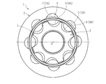
- joint center plane in a state where the operating angle is 0 ° is synonymous with a plane including the joint center and extending in a direction perpendicular to the axis of the joint in a state where the operating angle is 0 °. Refers to P (see, eg, FIG. 1A).
- FIG. 1 It is a figure for demonstrating the dimension of each part of the fixed type constant velocity universal joint shown in FIG. It is a schematic diagram which shows the state which the constant velocity universal joint shown in FIG. 1 took the maximum operating angle.
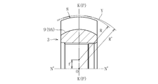
- FIG. 4 is a cross-sectional view of the track groove 7A shown in FIG. 2A as viewed in a plane M including the ball track center line X and the joint center O, that is, an angle ⁇ in the circumferential direction with respect to the joint axis NN.
- FIG. 6 is a cross-sectional view in a plane including an inclination axis N′-N ′ inclined by a distance of FIG. 4 shows only the track groove 7A among the track grooves 7A and 7B having different inclination directions.
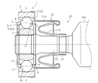
- a track groove 7A is formed in the spherical inner peripheral surface 6 of the outer joint member 2 along the axial direction.
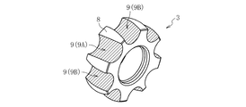
- 6A and 6B show dimensional characteristics of the constant velocity universal joint 1 of the present embodiment specialized for the propeller shaft.
- 6A and 6B are both cross-sections along the axis NN of the joint, but the track grooves 7 and 9 shown in both figures are similar to the track grooves 7 and 9 shown in FIG.
- the ball 4 is formed on the defining surface of the track groove 7 (7A, 7B), which is a portion (surface) where the ball 4 as the counterpart member repeatedly rolls.
- Surface treatment was performed to reduce the frictional resistance (sliding resistance).
- the portion to be subjected to the surface treatment is a portion indicated by hatching in FIG. 7A, and the same applies to FIGS. 7B, 8A, 8B and 9A to 9C referred to in the following description.
- the main difference between the constant velocity universal joints of the second and third embodiments and the fixed type constant velocity universal joint 1 of the first embodiment described above is that the center of curvature of the track groove (ball track center line) is the joint. Is located at a position offset by f in the radial direction with respect to the axial line NN (there is no axial offset with respect to the joint center O). That is, in the second and third embodiments, the center of curvature of the ball track center line of the track groove is offset by f in the radial direction on the joint center plane P including the perpendicular K and having an operating angle of 0 °.
Landscapes
- Engineering & Computer Science (AREA)
- General Engineering & Computer Science (AREA)
- Mechanical Engineering (AREA)
- Rolling Contact Bearings (AREA)
Abstract
Dans ce joint homocinétique de type fixe (1), à rainures de pistes croisées, les rainures de pistes (7) d'un élément de joint externe (2) forment un arc, le centre de courbure étant le centre du joint (O), et sont inclinées dans le sens circonférentiel par rapport à l'axe N-N du joint, ledit sens d'inclinaison étant opposé à celui des rainures de pistes (7) adjacentes dans le sens circonférentiel, et les rainures de pistes (9) d'un élément de joint interne (3) sont disposées en symétrie spéculaire avec la paire de rainures de pistes (7) de l'élément de joint externe (2) en référence au plan central de joint (P) dans un état dans lequel l'angle de travail est de 0 °. Les rainures de pistes (7, 9) des deux éléments de joint (2, 3) ont une longueur correspondant à l'angle de travail maximum θmax calculé à partir de l'arbre à cardan, et le traitement de surface pour diminuer la résistance de frottement (résistance au glissement) avec les billes (4) est effectué sur des surfaces définissant les rainures formant pistes (7) de l'élément de joint externe (2).
Priority Applications (3)
| Application Number | Priority Date | Filing Date | Title |
|---|---|---|---|
| CN201480036637.4A CN105339692A (zh) | 2013-06-26 | 2014-05-26 | 固定式等速万向联轴器 |
| US14/899,856 US10066674B2 (en) | 2013-06-26 | 2014-05-26 | Fixed-type constant velocity universal joint |
| EP14817418.8A EP3015729B1 (fr) | 2013-06-26 | 2014-05-26 | Joint homocinétique de type fixe |
Applications Claiming Priority (2)
| Application Number | Priority Date | Filing Date | Title |
|---|---|---|---|
| JP2013-133809 | 2013-06-26 | ||
| JP2013133809A JP2015010616A (ja) | 2013-06-26 | 2013-06-26 | 固定式等速自在継手 |
Publications (1)
| Publication Number | Publication Date |
|---|---|
| WO2014208241A1 true WO2014208241A1 (fr) | 2014-12-31 |
Family
ID=52141593
Family Applications (1)
| Application Number | Title | Priority Date | Filing Date |
|---|---|---|---|
| PCT/JP2014/063853 WO2014208241A1 (fr) | 2013-06-26 | 2014-05-26 | Joint homocinétique de type fixe |
Country Status (5)
| Country | Link |
|---|---|
| US (1) | US10066674B2 (fr) |
| EP (1) | EP3015729B1 (fr) |
| JP (1) | JP2015010616A (fr) |
| CN (1) | CN105339692A (fr) |
| WO (1) | WO2014208241A1 (fr) |
Families Citing this family (1)
| Publication number | Priority date | Publication date | Assignee | Title |
|---|---|---|---|---|
| TWI687333B (zh) * | 2019-05-17 | 2020-03-11 | 陳鵬任 | 汽車前輪傳動轉向裝置 |
Citations (6)
| Publication number | Priority date | Publication date | Assignee | Title |
|---|---|---|---|---|
| JP2007503556A (ja) * | 2003-08-22 | 2007-02-22 | ゲー カー エヌ ドライブライン ドイチュラント ゲゼルシャフト ミット ベシュレンクテル ハフツング | ねじれたトラック横断面を有する固定式ボールジョイント |
| JP2009250342A (ja) * | 2008-04-04 | 2009-10-29 | Ntn Corp | 等速自在継手 |
| JP2009250365A (ja) | 2008-04-08 | 2009-10-29 | Ntn Corp | 等速自在継手 |
| JP2010043667A (ja) * | 2008-08-11 | 2010-02-25 | Ntn Corp | 固定式等速自在継手 |
| JP2010527427A (ja) * | 2007-05-18 | 2010-08-12 | ゲーカーエン ドライブライン ドイチュラント ゲーエムベーハー | 低押込み力による等速押込みボールジョイント |
| JP2011112117A (ja) * | 2009-11-25 | 2011-06-09 | Ntn Corp | 固定式等速自在継手 |
Family Cites Families (8)
| Publication number | Priority date | Publication date | Assignee | Title |
|---|---|---|---|---|
| JPS5969523A (ja) * | 1982-10-08 | 1984-04-19 | Matsushita Electric Ind Co Ltd | 流体軸受 |
| US6736729B2 (en) * | 2002-07-03 | 2004-05-18 | Gkn Automotive, Inc. | Constant velocity joint and method of making same |
| JP2004301314A (ja) * | 2003-04-01 | 2004-10-28 | Nsk Ltd | 転がり軸受 |
| WO2009145035A1 (fr) | 2008-05-30 | 2009-12-03 | Ntn株式会社 | Joint homocinétique de type fixe |
| JP5420369B2 (ja) * | 2009-10-08 | 2014-02-19 | Ntn株式会社 | 固定式等速自在継手 |
| US9133886B2 (en) * | 2011-03-18 | 2015-09-15 | Ntn Corporation | Constant velocity universal joint |
| US9163672B2 (en) | 2011-05-30 | 2015-10-20 | Ntn Corporation | Fixed constant velocity universal joint |
| CN202203295U (zh) * | 2011-08-28 | 2012-04-25 | 襄阳博亚精工装备股份有限公司 | 内外沟道表面涂覆复合层的球笼联轴器 |
-
2013
- 2013-06-26 JP JP2013133809A patent/JP2015010616A/ja active Pending
-
2014
- 2014-05-26 CN CN201480036637.4A patent/CN105339692A/zh active Pending
- 2014-05-26 WO PCT/JP2014/063853 patent/WO2014208241A1/fr active Application Filing
- 2014-05-26 US US14/899,856 patent/US10066674B2/en active Active
- 2014-05-26 EP EP14817418.8A patent/EP3015729B1/fr active Active
Patent Citations (6)
| Publication number | Priority date | Publication date | Assignee | Title |
|---|---|---|---|---|
| JP2007503556A (ja) * | 2003-08-22 | 2007-02-22 | ゲー カー エヌ ドライブライン ドイチュラント ゲゼルシャフト ミット ベシュレンクテル ハフツング | ねじれたトラック横断面を有する固定式ボールジョイント |
| JP2010527427A (ja) * | 2007-05-18 | 2010-08-12 | ゲーカーエン ドライブライン ドイチュラント ゲーエムベーハー | 低押込み力による等速押込みボールジョイント |
| JP2009250342A (ja) * | 2008-04-04 | 2009-10-29 | Ntn Corp | 等速自在継手 |
| JP2009250365A (ja) | 2008-04-08 | 2009-10-29 | Ntn Corp | 等速自在継手 |
| JP2010043667A (ja) * | 2008-08-11 | 2010-02-25 | Ntn Corp | 固定式等速自在継手 |
| JP2011112117A (ja) * | 2009-11-25 | 2011-06-09 | Ntn Corp | 固定式等速自在継手 |
Also Published As
| Publication number | Publication date |
|---|---|
| EP3015729A1 (fr) | 2016-05-04 |
| US10066674B2 (en) | 2018-09-04 |
| CN105339692A (zh) | 2016-02-17 |
| EP3015729B1 (fr) | 2020-01-15 |
| EP3015729A4 (fr) | 2017-02-22 |
| US20160146260A1 (en) | 2016-05-26 |
| JP2015010616A (ja) | 2015-01-19 |
Similar Documents
| Publication | Publication Date | Title |
|---|---|---|
| JP6114644B2 (ja) | 固定式等速自在継手 | |
| JP5964030B2 (ja) | 固定式等速自在継手 | |
| EP2530346B1 (fr) | Joint à vitesse constante de type balle glissante pour véhicule | |
| WO2012005087A1 (fr) | Joint homocinétique de type fixe | |
| WO2012169299A1 (fr) | Joint homocinétique fixe | |
| JP2010043667A (ja) | 固定式等速自在継手 | |
| WO2012165096A1 (fr) | Joint de cardan homocinétique fixe | |
| JP2012017809A5 (fr) | ||
| JP6113459B2 (ja) | 固定式等速自在継手 | |
| JP5840463B2 (ja) | 固定式等速自在継手 | |
| JP5955732B2 (ja) | 固定式等速自在継手 | |
| WO2014057781A1 (fr) | Joint universel homocinétique de type fixe | |
| WO2014069210A1 (fr) | Joint à rotule à vitesse constante fixe | |
| JP5882050B2 (ja) | 固定式等速自在継手 | |
| JP6199159B2 (ja) | 固定式等速自在継手 | |
| WO2014208241A1 (fr) | Joint homocinétique de type fixe | |
| CN108779807B (zh) | 固定式等速万向联轴器 | |
| JP5885997B2 (ja) | 固定式等速自在継手 | |
| JP5885998B2 (ja) | 固定式等速自在継手 | |
| JP6779723B2 (ja) | 摺動式等速自在継手 | |
| JP2014084952A (ja) | 固定式等速自在継手 | |
| WO2019003765A1 (fr) | Joint homocinétique de type fixe |
Legal Events
| Date | Code | Title | Description |
|---|---|---|---|
| WWE | Wipo information: entry into national phase |
Ref document number: 201480036637.4 Country of ref document: CN |
|
| 121 | Ep: the epo has been informed by wipo that ep was designated in this application |
Ref document number: 14817418 Country of ref document: EP Kind code of ref document: A1 |
|
| WWE | Wipo information: entry into national phase |
Ref document number: 14899856 Country of ref document: US |
|
| NENP | Non-entry into the national phase |
Ref country code: DE |
|
| WWE | Wipo information: entry into national phase |
Ref document number: 2014817418 Country of ref document: EP |