WO2014207873A1 - シザーズギヤ、動力伝達機構、ロボットおよびシザーズギヤの製造方法 - Google Patents
シザーズギヤ、動力伝達機構、ロボットおよびシザーズギヤの製造方法 Download PDFInfo
- Publication number
- WO2014207873A1 WO2014207873A1 PCT/JP2013/067715 JP2013067715W WO2014207873A1 WO 2014207873 A1 WO2014207873 A1 WO 2014207873A1 JP 2013067715 W JP2013067715 W JP 2013067715W WO 2014207873 A1 WO2014207873 A1 WO 2014207873A1
- Authority
- WO
- WIPO (PCT)
- Prior art keywords
- gear
- sub
- hole
- main gear
- main
- Prior art date
- Legal status (The legal status is an assumption and is not a legal conclusion. Google has not performed a legal analysis and makes no representation as to the accuracy of the status listed.)
- Ceased
Links
Images






Classifications
-
- B—PERFORMING OPERATIONS; TRANSPORTING
- B25—HAND TOOLS; PORTABLE POWER-DRIVEN TOOLS; MANIPULATORS
- B25J—MANIPULATORS; CHAMBERS PROVIDED WITH MANIPULATION DEVICES
- B25J9/00—Program-controlled manipulators
- B25J9/10—Program-controlled manipulators characterised by positioning means for manipulator elements
- B25J9/102—Gears specially adapted therefor, e.g. reduction gears
- B25J9/103—Gears specially adapted therefor, e.g. reduction gears with backlash-preventing means
-
- F—MECHANICAL ENGINEERING; LIGHTING; HEATING; WEAPONS; BLASTING
- F16—ENGINEERING ELEMENTS AND UNITS; GENERAL MEASURES FOR PRODUCING AND MAINTAINING EFFECTIVE FUNCTIONING OF MACHINES OR INSTALLATIONS; THERMAL INSULATION IN GENERAL
- F16H—GEARING
- F16H55/00—Elements with teeth or friction surfaces for conveying motion; Worms, pulleys or sheaves for gearing mechanisms
- F16H55/02—Toothed members; Worms
- F16H55/17—Toothed wheels
- F16H55/18—Special devices for taking up backlash
Definitions
- the disclosed embodiment relates to a scissors gear, a power transmission mechanism, a robot, and a method of manufacturing a scissors gear.
- the scissor gear described above is configured to include a main gear, a sub gear, and a spring.
- spring accommodating grooves are respectively provided on the overlapping surfaces where the main gear and the sub gear overlap, and a holding portion for holding the spring is attached to the accommodating groove.
- a spring is installed in the housing groove to which the holding portion is attached, and the main gear and the sub gear are overlapped and connected.
- the spring applies urging forces to the main gear and the sub gear in mutually different rotational directions, so that the mating gear is sandwiched between the main gear and the sub gear to reduce backlash.
- One aspect of the embodiments has been made in view of the above, and an object thereof is to provide a scissors gear, a power transmission mechanism, a robot, and a method of manufacturing a scissors gear that can improve assembly while simplifying the configuration.
- a scissor gear includes a main gear, a sub gear, a main gear hole, a sub gear hole, and a clamping member.
- the sub gear is superposed on the main gear.
- the main gear hole is formed in the overlapping surface overlapping with the sub gear of the main gear.
- the sub gear hole is an overlapping surface that overlaps the main gear of the sub gear, and is formed at a position corresponding to the main gear hole.
- the clamping member is clamped between the main gear hole and the sub gear hole while partially contacting the main gear hole and the sub gear hole.
- the clamping member is clamped in a state where the main gear and the sub gear are deformed by being shifted in mutually different rotation directions, and in the deformed state, the clamping member is connected to the main gear hole portion and the sub gear hole portion. It has resilience that generates a repulsive force at the contact portion.
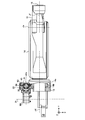
- FIG. 1 is a side view showing a robot provided with scissor gears according to the first embodiment.
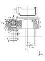
- FIG. 2 is a partial cross-sectional top view showing only the vicinity of the upper arm and first to third wrists shown in FIG.
- FIG. 3 is an enlarged partial cross-sectional top view showing the vicinity of the upper arm shown in FIG. 2 in an enlarged manner.
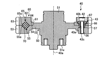
- 4 is an enlarged cross-sectional view showing the scissor gear shown in FIG.
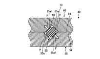
- FIG. 5 is a plan view of the scissor gear shown in FIG. 6 is a cross-sectional view taken along line VI-VI in FIG. FIG.
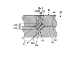
- FIG. 7 is a cross-sectional view taken along the line VI-VI showing a state in which the main gear and the sub gear are overlapped with the main gear hole and the sub gear hole facing each other.
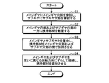
- FIG. 8 is a flowchart showing the procedure for assembling the scissors gear.
- FIG. 9 is an enlarged cross-sectional view showing a modification of the scissor gear according to the first embodiment.
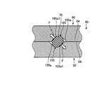
- FIG. 10A is an enlarged cross-sectional view showing the vicinity of the main gear hole and the sub-gear hole of the scissor gear according to the second embodiment.
- 10B is a cross-sectional view taken along the line VI-VI showing a cross section near the main gear hole portion and the sub gear hole portion of the scissor gear shown in FIG. 10A.
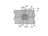
- 11A is an enlarged cross-sectional view of the vicinity of the main gear hole and the sub gear hole, showing a modification of the scissor gear according to the second embodiment.
- 11B is a cross-sectional view taken along the line VI-VI showing a cross section near the main gear hole and the sub gear hole of the scissor gear shown in FIG. 11A.
- FIG. 12A is an enlarged cross-sectional view of the vicinity of the main gear hole and the sub-gear hole showing a modification of the scissor gear according to the second embodiment.
- 12B is a cross-sectional view taken along the line VI-VI showing a cross section near the main gear hole portion and the sub gear hole portion of the scissor gear shown in FIG. 12A.
- FIG. 1 is a side view showing a robot provided with scissor gears according to the first embodiment.
- the vertical upward direction is a positive direction
- the vertical downward direction is a negative direction
- the Z axis is a negative direction
- the horizontal direction on the paper is the Y axis
- the front side from the back is the X axis.
- a three-dimensional orthogonal coordinate system is illustrated. Such an orthogonal coordinate system may also be shown in other drawings used in the following description.
- X-axis direction means the axis and the Z-axis direction, and is not limited to the expressed direction.
- the robot 1 is an articulated robot having a plurality of links and a plurality of rotation axes (joint axes) Ja to Jf for connecting the links.
- the robot 1 includes, as links, a base 10, a turning unit 11, a lower arm 12, an upper arm (first link) 13, and a first wrist (second link, predetermined member) 14.
- the second wrist portion 15 and the third wrist portion 16 are connected to each other so as to be rotatable.
- the swivel unit 11 is connected to the base 10 so as to be rotatable about the rotation axis Ja, and the lower arm 12 is rotatable relative to the swivel unit 11 about the rotation axis Jb perpendicular to the rotation axis Ja.
- the upper arm 13 is connected to the lower arm 12 so as to be rotatable about a rotation axis Jc parallel to the rotation axis Jb, and the first wrist portion 14 is perpendicular to the rotation axis Jc with respect to the upper arm 13. It is connected so as to be rotatable around the rotation axis Jd.
- the second wrist portion 15 is connected to the first wrist portion 14 so as to be rotatable around a rotation axis Je perpendicular to the rotation axis Jd
- the third wrist portion 16 is connected to the second wrist portion 15. , And are connected so as to be rotatable around a rotation axis Jf perpendicular to the rotation axis Je.
- the robot 1 further includes actuators Ma to Mf for rotationally driving the swivel unit 11, the lower arm 12, the upper arm 13, and the first to third wrist parts 14, 15, and 16 (only the actuator Md is shown in the figure). Is provided.
- Each of the actuators Ma to Mf is specifically a servo motor, for example.
- the actuators Ma to Mf are servo motors, the present invention is not limited thereto, and may be other types of motors such as a hydraulic motor. In the following, the actuator is expressed as “motor”.
- the motor Ma is connected to the turning unit 11 and rotationally drives the turning unit 11.
- the motor Mb is connected to the lower arm 12 to rotationally drive the lower arm 12, and the motor Mc is connected to the upper arm 13 to rotationally drive the upper arm 13.
- the motor Md is attached to the upper arm 13 and an output shaft (not visible in FIG. 1) is connected to the first wrist portion 14 via the power transmission mechanism 20. Accordingly, the motor Md transmits the driving force to the first wrist portion 14 via the power transmission mechanism 20 and rotationally drives the first wrist portion 14.
- the power transmission mechanism 20 includes a gear that transmits the driving force of the motor Md to the first wrist portion 14, and a scissors gear, for example, is used as the gear.
- a gear that transmits the driving force of the motor Md to the first wrist portion 14, and a scissors gear, for example, is used as the gear.
- the configuration of the power transmission mechanism 20 including the scissor gear will be described in detail later.
- the motor Me is connected to the second wrist 15 and rotates the second wrist 15.
- the motor Mf is connected to the third wrist portion 16 and rotationally drives the third wrist portion 16.
- a signal indicating an operation command is input to the motors Ma to Mf from a control device (not shown), and the operation is controlled based on the signal. Further, an end effector (for example, a hand) (not shown) is attached to the third wrist portion 16.
- the robot 1 controls the operations of the motors Ma to Mf and the like by the control device, so that, for example, the position and angle of the end effector are appropriately changed, and a predetermined work such as a work transfer work or an assembly work is performed. And so on.
- a hand is provided as an end effector.
- work etc. were mentioned as an example of the predetermined
- the driving forces of the motors Ma to Mf are transmitted to the turning portion 11, the lower arm 12, the upper arm 13, and the first to third wrist portions 14, 15, and 16 through the power transmission mechanism, respectively.
- the power transmission mechanism is composed of a gear or the like, and for example, a scissors gear capable of reducing backlash may be used as the gear.
- the scissor gear includes a main gear and a sub gear superposed on the main gear, and is configured to sandwich the mating gear between the main gear and the sub gear by applying urging forces to the main gear and the sub gear in different rotational directions.
- urging forces for example, if the above-described urging force is applied using a spring, the configuration of the scissors gear may be complicated.
- a spring for example, a spring accommodating groove is provided on each overlapping surface where the main gear and the sub gear overlap, a mounting hole is formed in the receiving groove, and a holding portion for holding the spring is attached to the mounting hole. Then, a spring is installed in the housing groove to which the holding part is attached, and the main gear and the sub gear are overlapped and connected.
- the structure of the scissor gear may be complicated because the holding part and the mounting hole are required. there were.
- the holding portion or the like since the holding portion or the like is required, there is a possibility that the assembling property of the scissor gear is lowered.
- the structure is simplified and the assemblability is improved.
- the configuration of the power transmission mechanism 20 including the scissor gear will be described in detail.
- FIG. 2 is a partial cross-sectional top view showing only the vicinity of the upper arm 13 shown in FIG. 1 and the first to third wrist portions 14, 15, and 16.
- FIG. 3 is an enlarged view of the vicinity of the upper arm 13 shown in FIG. FIG. In FIGS. 2 and 3, the swivel unit 11 and the lower arm 12 are not shown for simplification.
- the power transmission mechanism 20 is interposed between the motor Md and the first wrist portion 14.
- the power transmission mechanism 20 includes a wave gear device 30 and a scissors gear 40.
- the wave gear device 30 includes a flex spline 31, a wave generator 32, and a circular spline 33, and functions as a speed reduction mechanism.
- the flexspline 31 has flexibility, and teeth are formed on the outer peripheral surface. Further, the flexspline 31 is connected to the scissors gear 40 at the end.
- the wave generator 32 is connected to the output shaft 21 of the motor Md and is formed in an elliptical shape when viewed in the Y-axis direction.
- the wave generator 32 is fitted inside the flexspline 31 via a bearing 34.
- the circular spline 33 has teeth formed on the inner peripheral surface and is disposed outside the flexspline 31. Note that the number of teeth of the circular spline 33 is set to be different from the number of teeth of the flexspline 31, and is set to be larger than the number of teeth of the flexspline 31, for example.
- the flexspline 31 is partially meshed with the teeth of the circular spline 33 in a state where the flexspline 31 is deformed into the shape of the wave generator 32, that is, an elliptical shape.
- the flexspline 31 is also rotated at a reduced speed while moving the meshing portion with the circular spline 33 in the circumferential direction. . Then, the rotation of the flexspline 31 is output to the scissor gear 40.
- FIG. 4 is an enlarged sectional view showing the scissors gear 40 shown in FIG. 3
- FIG. 5 is a plan view of the scissors gear 40 shown in FIG.
- the scissors gear 40 includes a main gear 50, a sub gear 60, and a clamping member 70 (indicated by a one-dot chain line in FIG. 5).
- the main gear 50 and the sub gear 60 are superposed, and an urging force is applied from the clamping member 70 to the main gear 50 and the sub gear 60 in mutually different rotational directions, whereby a mating gear (a driven gear 14b to be described later) (See FIG. 3).
- the main gear 50 includes a shaft 51, a main gear main body 52, and a tooth portion 53 as shown in FIG.
- the shaft 51 is formed solid inside, and the flex spline 31 that is the output side of the wave gear device 30 is connected to the bolt hole 51a.
- the shaft 51 is rotatably supported by the bearing 41 (see FIG. 3).
- the main gear main body 52 is continuously formed from the vicinity of the center of the shaft 51 and is formed in a disc shape that protrudes outward in the radial direction of the shaft 51.
- the teeth 53 are formed on the outer peripheral surface of the main gear main body 52.
- the sub gear 60 includes a sub gear main body portion 62 having a hollow portion 61 and a tooth portion 63.
- the sub gear main body 62 is formed in a disk shape having substantially the same diameter as the main gear 50 (more precisely, the main gear main body 52).
- the main gear 50 and the sub gear 60 are superposed by inserting the shaft 51 of the main gear 50 and a part of the main gear main body 52 into the hollow portion 61 of the sub gear main body 62.
- the overlapping surface that overlaps the sub gear 60 in the main gear 50 is indicated by reference numeral 54
- the overlapping surface that overlaps the main gear 50 in the sub gear 60 is indicated by reference numeral 64.
- the tooth part 63 is formed on the outer peripheral surface of the sub-gear main body part 62.
- gear part 63 of the sub gear 60 are spur gears, for example, it is not restricted to this, For example, other types of gears, such as a helical gear, may be sufficient.
- the tooth portion 53 and the tooth portion 63 have substantially the same values such as the number of teeth and the circular pitch.
- a main gear hole 55 is formed in the overlapping surface 54 of the main gear 50, while a sub gear hole 65 is formed in the overlapping surface 64 of the sub gear 60. Note that the main gear hole 55 and the sub gear hole 65 are not shown in appearance when the main gear 50 and the sub gear 60 are overlapped with each other.
- FIG. 6 is a cross-sectional view taken along the line VI-VI in FIG. 5 and shows a cross section near the main gear hole 55 and the sub gear hole 65.
- each member such as the clamping member 70 is exaggerated and schematically shown for convenience of understanding.
- the main gear hole 55 is formed in a shape having a conical surface 55a, specifically, for example, a conical shape.
- the main gear hole 55 is formed such that an angle ⁇ (see FIG. 6) formed by the conical surface 55a and the overlapping surface 54 is a predetermined angle ⁇ 1.
- the predetermined angle ⁇ 1 is, for example, 0 degree ⁇ 1 ⁇ 90 degrees, and specifically, for example, 45 degrees.
- a plurality of (for example, three) main gear hole portions 55 formed as described above are provided on the overlapping surface 54 of the main gear 50 as shown in FIG. Specifically, the plurality of main gear hole portions 55 are provided at intervals of a predetermined angle (for example, 120 degrees) with respect to the rotation shaft 40a of the scissors gear 40.
- a predetermined angle for example, 120 degrees
- the sub gear hole portion 65 is formed in a shape having a conical surface 65a, specifically, for example, a conical shape, like the main gear hole portion 55.
- the sub gear hole 65 is formed such that an angle ⁇ (see FIG. 6) formed by the conical surface 65a and the overlapping surface 64 is a predetermined angle ⁇ 1.
- the predetermined angle ⁇ 1 is, for example, 0 degree ⁇ 1 ⁇ 90 degrees, and specifically, for example, 45 degrees which is the same as that of the main gear hole 55.
- the specific angles ⁇ 1 and ⁇ 1 have been described with specific numerical values. However, this is an example and is not limited.
- a plurality of (for example, three) sub gear hole portions 65 are provided on the overlapping surface 64 of the sub gear 60. Specifically, the plurality of sub-gear hole portions 65 are provided at intervals of a predetermined angle (for example, 120 degrees) around the rotation shaft 40a of the scissors gear 40. That is, the sub gear hole 65 is formed at a position corresponding to the main gear hole 55.
- the opening area of the sub gear hole 65 (corresponding to the bottom area of the cone) is substantially the same as the opening area of the main gear hole 55.
- the main gear hole 55 and the sub gear hole 65 have substantially the same shape.
- the main gear hole portion 55 and the sub gear hole portion 65 are configured to have substantially the same shape.
- the present invention is not limited to this, and may be configured to have different shapes.
- the number of the main gear hole 55 and the sub gear hole 65 is three, for example, but may be one, two, or four or more, respectively.
- the scissor gear 40 according to the present embodiment is configured such that when the main gear 50 and the sub gear 60 are assembled with each other, the main gear hole 55 and the sub gear hole 65 are opposed to each other as described later.
- a biconical space S is formed by the main gear hole 55 and the sub gear hole 65.
- the clamping member 70 is disposed in the space S.
- the clamping member 70 is made of, for example, an elastically deformable material (for example, rubber, specifically, urethane rubber, silicon rubber, natural rubber, or the like). Although the inside of the clamping member 70 is solid, it may be configured to be hollow. Further, the sandwiching member 70 may have a multilayer structure, and the surface side layer may be made of the elastically deformable material described above.
- an elastically deformable material for example, rubber, specifically, urethane rubber, silicon rubber, natural rubber, or the like.
- the sandwiching member 70 is deformed when the scissors gear 40 is assembled (described later), but in a state before being deformed, that is, in a state shown in FIG.
- the clamping member 70 can be easily manufactured by making the clamping member 70 spherical.
- the sandwiching member 70 has a spherical shape, but this is an example and is not limited. That is, the clamping member 70 may have other shapes such as a spheroid such as a columnar shape, a prismatic shape, or a rugby ball shape.
- the diameter of the clamping member 70 is set to a value larger than the separation distance L1 between the conical surface 55a of the opposing main gear hole 55 and the conical surface 65a of the sub gear hole 65, for example. Accordingly, the clamping member 70 is clamped while being in contact with the main gear hole 55 and the sub gear hole 65 in a state where it is disposed between the main gear hole 55 and the sub gear hole 65.
- the sandwiching member 70 has a spherical shape, and the main gear hole portion 55 and the sub gear hole portion 65 both have the conical surfaces 55a and 65a. Therefore, the sandwiching member 70 includes the main gear hole portion 55 and the sub gear portion. It will be pinched while partially contacting the hole 65.
- the portions 55 a 1 and 65 a 1 that are in contact with the clamping member 70 are spaced apart from the overlapping surfaces 54 and 64 of the main gear 50 and the sub gear 60 by a predetermined distance L 50 and L 60. It becomes. That is, the main gear hole 55 and the sub gear hole 65 are configured such that the clamping member 70 does not contact the overlapping surfaces 54 and 64 of the main gear 50 and the sub gear 60.
- the scissors gear 40 shifts the main gear 50 and the sub gear 60 in different rotational directions. Specifically, for example, the main gear 50 is shifted counterclockwise in FIG. 5 and the sub gear 60 is shifted clockwise. assemble.
- the main gear 50 and the sub-gear 60 hold the holding member 70 in the state shown in FIG. 7 and then shift them in different rotational directions.
- the clamping member 70 is clamped between the main gear 50 and the sub gear 60 in a deformed state as shown in FIG.
- the holding member 70 is made of a material that is elastically deformed as described above, in the deformed state, the repulsive force F against the contact portions 55a1 and 65a1 with the main gear hole portion 55 and the sub gear hole portion 65. Produce. In this manner, the clamping member 70 has a resilience that generates a repulsive force F at the contact portions 55a1 and 65a1 with the main gear hole 55 and the sub gear hole 65.
- the tooth portion 53 of the main gear 50 and the tooth portion 63 of the sub gear 60 will be described. As shown in FIG. 6, in a state where the main gear 50 and the sub gear 60 are shifted and the clamping member 70 is deformed, the tooth portion 53 and the tooth portion 63 are in a state in which the teeth are aligned, in other words, the phase is the same. State.
- the main gear 50 and the sub gear 60 are meshed with the mating gear in the state where the teeth 53 and the teeth 63 are in the same phase, that is, in the state shown in FIG. Therefore, when a repulsive force F is generated from the above-described clamping member 70 to the contact portions 55a1 and 65a1, the tooth portion 53 and the tooth portion 63 are slightly displaced, so that the mating gear is sandwiched between the main gear 50 and the sub gear 60. As a result, backlash can be reduced.
- the urging forces applied to the main gear 50 and the sub gear 60 in different rotational directions are generated by the repulsive force F of the clamping member 70.
- a spring holding portion or the like can be eliminated, so that the configuration of the scissors gear 40 can be simplified.
- the clamp member 70 in a deformed state will be further described.
- the pinching member 70 is spherical, and both the main gear hole 55 and the sub gear hole 65 have the conical surfaces 55a and 65a. Therefore, the direction of the repulsive force F is as shown in FIG. It is not parallel to the overlapping surfaces 54 and 64 of the main gear 50 and the sub gear 60.
- the shearing stress (specifically, the stress acting in the direction parallel to the overlapping surfaces 54 and 64) that the clamping member 70 receives from the main gear 50 or the sub gear 60 is applied to the overlapping surfaces 54 and 64.
- the holding member 70 is in a position where the contact portions 55a1 and 65a1 with the main gear hole 55 and the sub gear hole 65 are separated from the overlapping surfaces 54 and 64 by a predetermined distance L50 and L60, that is, on the overlapping surfaces 54 and 64. Did not abut. Thereby, in the clamping member 70, the shear stress does not act directly from the overlapping surfaces 54 and 64, so that it is possible to prevent the shear stress from being concentrated locally on the portions near the overlapping surfaces 54 and 64. .
- the main gear 50 and the sub gear 60 are engaged with each other by the bolt 42 while maintaining a relatively rotatable state, and thus the superposed main gear 50 and the sub gear 60 are disengaged. I try to prevent it.
- the main gear 50 has a bolt hole 56 in which a female screw corresponding to the bolt 42 is formed, and a concave portion 57 that is larger in diameter than the bolt hole 56 and opens to the overlapping surface 54 side while communicating with the bolt hole 56. It is formed.
- the sub gear 60 has a diameter larger than that of the recess 57 and passes through the insertion surface 66 at a position facing the recess 57, and is continuous from the insertion hole 66, and is open to the outside of the sub gear 60.
- a recess 67 is formed.
- the slider 43 is disposed in the recess 57, the loose insertion hole 66 and the recess 67.
- the slider 43 includes a fitting portion 43 a that fits into the recess 57 while being loosely inserted into the insertion hole 66, and a flange portion 43 b that is positioned while being loosely inserted into the recess 67. Further, the slider 43 is formed with an insertion hole 43c through which the bolt 42 is inserted at the center thereof.
- the slider 43 is fitted to the main gear 50 by fitting the fitting portion 43 a to the recess 57.
- the slider 43 allows the sub gear 60 to move in the rotational direction by loosely inserting the fitting portion 43a into the loose insertion hole 66 and positioning the flange portion 43b while loosely inserting the flange portion 43b into the concave portion 67.
- the main gear 50 and the sub gear 60 are engaged by screwing the bolt 42 into the bolt hole 56 while inserting the bolt 42 into the insertion hole 43 c of the slider 43.
- the configuration of the bolts 42 and the like for engaging the main gear 50 and the sub gear 60 described above is provided at a plurality of locations (for example, 3 locations) in the scissors gear 40 as shown in FIG. Specifically, the configuration of the bolts 42 and the like is provided between the portions where the main gear hole portion 55 and the sub gear hole portion 65 are formed, and is spaced at a predetermined angle (for example, 120 degrees) with respect to the rotation shaft 40a of the scissors gear 40. Provided.
- the scissor gear 40 configured as described above is connected to the first wrist portion 14.
- the first wrist portion 14 includes a cylindrical shaft 14a, and a driven gear 14b is formed at an end portion of the shaft 14a.
- the scissors gear 40 is meshed with the driven gear 14b, which is the counterpart gear. Thereby, the scissors gear 40 transmits the driving force output from the motor Md to the first wrist portion 14 to drive the first wrist portion 14 to rotate.
- FIG. 8 is a flowchart showing the procedure for assembling the scissor gear 40.
- the main gear hole 55 is formed in the overlapping surface 54 of the main gear 50, and the sub gear hole 65 is formed in the overlapping surface 64 of the sub gear 60 (step S1). At this time, the sub gear hole 65 is formed at a position corresponding to the main gear hole 55 on the overlapping surface 64 of the sub gear 60.
- the clamping member 70 is placed in one of the drilled main gear hole 55 and sub-gear hole 65. Specifically, for example, the clamping member 70 is placed in the main gear hole 55 (step S2). In the above description, the clamping member 70 is placed in the main gear hole 55, but it may be placed in the sub gear hole 65.
- the main gear 50 and the sub gear 60 are overlapped with the other of the main gear hole 55 and the sub gear hole 65 (specifically, the sub gear hole 65) facing one (specifically, the main gear hole 55).
- the placed clamping member 70 is clamped between the main gear hole 55 and the sub gear hole 65 while partially contacting the main gear hole 55 and the sub gear hole 65 (step S3).
- step S4 the clamping member 70 is clamped in a deformed state (step S4), and the repulsive force F is applied to the contact portions 55a1, 65a1 of the main gear hole 55 and the sub gear hole 65 in the deformed clamping member 70.
- the scissors gear 40 is incorporated into the power transmission mechanism 20 and thus the robot 1 by engaging the scissors gear 40 configured as described above with the driven gear 14 b of the first wrist portion 14. .
- the assembly of the springs and the like can be made unnecessary as compared with a scissors gear having a configuration using a spring, a holding portion, and the like, thereby improving the assemblability of the scissors gear 40. Can be made.
- the scissors gear 40 includes the main gear 50, the sub gear 60, the main gear hole 55, the sub gear hole 65, and the clamping member 70.
- the main gear hole 55 is formed in the overlapping surface 54 of the main gear 50.
- the sub gear hole 65 is formed on the overlapping surface 64 of the sub gear 60 at a position corresponding to the main gear hole 55.
- the sandwiching member 70 is sandwiched between the main gear hole 55 and the sub gear hole 65 while partially contacting the main gear hole 55 and the sub gear hole 65.
- the clamping member 70 is clamped in a state where the main gear 50 and the sub gear 60 are deformed by being shifted in mutually different rotation directions, and in the deformed state, the clamping member 70 is connected to the main gear hole 55 and the sub gear hole 65.
- the contact portions 55a1 and 65a1 have resilience that generates a repulsive force F.
- the shaft 51 of the main gear 50 is solid.
- the shaft 51 may be provided with a hollow portion 51b. Good.
- FIG. 9 is an enlarged cross-sectional view showing a modified example of the scissors gear 40 according to the first embodiment.
- a cable or the like can be inserted through the hollow portion 51 b of the shaft 51, and thus the configuration in the vicinity of the scissors gear 40 can be made compact.
- FIG. 10A is an enlarged cross-sectional view showing the vicinity of the main gear hole 155 and the sub gear hole 165 of the scissors gear 40 according to the second embodiment.
- 10B is a cross-sectional view taken along the line VI-VI similar to FIG. 6, showing a cross section near the main gear hole 155 and the sub gear hole 165 of the scissor gear 40 shown in FIG. 10A.
- the same components as those in the first embodiment are denoted by the same reference numerals and description thereof is omitted.
- the main gear hole 155 is formed in a shape having a conical surface 155a and is substantially conical, but the apex portion of the conical shape conforms to the outer shape of the clamping member 70, Specifically, it is configured to be hemispherical.
- the sub-gear hole 165 has substantially the same shape as the main gear hole 155. That is, the sub-gear hole 165 is formed in a shape having a conical surface 165a and is substantially conical, but the apex of the conical shape conforms to the outer shape of the sandwiching member 70 (specifically, hemispherical) It is comprised so that.
- the areas of the portions 155a1 and 165a1 in contact with the clamping member 70 in the main gear hole 155 and the sub gear hole 165 are compared with those in the first embodiment. Can be enlarged.
- the shear stress received by the clamping member 70 from the main gear 50 or the sub gear 60 can be dispersed, in other words, the shear stress can be effectively prevented from being concentrated locally.
- the remaining configuration and effects are the same as those in the first embodiment, and a description thereof will be omitted.
- the shapes of the main gear hole and the sub-gear hole are deformed with respect to the first embodiment, but the holding member may be similarly deformed.
- FIG. 11A is an enlarged cross-sectional view of the vicinity of the main gear hole 255 and the sub-gear hole 265 similar to FIG. 10A, showing a modification of the scissor gear 40 according to the second embodiment.
- 11B is a cross-sectional view taken along the line VI-VI similar to FIG. 6, showing a cross section near the main gear hole 255 and the sub gear hole 265 of the scissor gear 40 shown in FIG. 11A.
- the holding member 270 is formed in a columnar shape, for example. Further, the main gear hole portion 255 and the sub gear hole portion 265 are formed in a hemispherical shape in the second embodiment in a shape corresponding to the outer shape of the holding member 270, that is, in a columnar shape.
- the areas of the portions 255a1 and 265a1 that are in contact with the clamping member 270 can be enlarged as compared with the first embodiment.
- the shear stress received by the clamping member 270 from the main gear 50 or the sub gear 60 can be dispersed, in other words, the shear stress can be effectively prevented from being concentrated locally.
- both the main gear hole portion 255 and the sub gear hole portion 265 have a shape having conical surfaces 255a and 265a. Therefore, the main gear hole portion 255 and the sub gear hole portion 265 are configured such that the clamping member 270 does not contact the overlapping surfaces 54 and 64 of the main gear 50 and the sub gear 60. Thereby, in the clamping member 270, the shear stress does not act directly from the overlapping surfaces 54 and 64, and it is possible to reliably prevent the shear stress from being concentrated locally on the portions near the overlapping surfaces 54 and 64. it can.
- main gear hole portion, the sub gear hole portion, and the clamping member may be deformed into shapes as shown in FIGS. 12A and 12B.
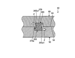
- FIG. 12A is an enlarged cross-sectional view of the vicinity of the main gear hole 355 and the sub gear hole 365 similar to FIG. 10A, showing a modification of the scissors gear 40 according to the second embodiment.
- 12B is a cross-sectional view taken along the line VI-VI similar to FIG. 6, showing a cross section near the main gear hole 355 and the sub gear hole 365 of the scissor gear 40 shown in FIG. 12A.
- the sandwiching member 370 is formed, for example, in a substantially cylindrical shape, and includes a constricted portion 370a.
- the constricted portion 370a is formed at a central portion of the clamping member 370, more specifically, at a portion of the clamping member 370 located near the overlapping surfaces 54 and 64 of the main gear 50 and the sub gear 60.
- both the main gear hole portion 355 and the sub gear hole portion 365 are formed in a cylindrical shape. Therefore, the clamping member 370 is configured not to contact the overlapping surfaces 54 and 64 of the main gear 50 and the sub gear 60 by including the constricted portion 370a. Thereby, in the clamping member 370, the shear stress does not act directly from the superposed surfaces 54, 64, and it is possible to reliably prevent the shear stress from being concentrated locally on the portions near the superposed surfaces 54, 64. it can.
- the areas of the portions 355a1 and 365a1 that are in contact with the clamping member 370 can be enlarged as compared with the first embodiment. .
- the shear stress received by the clamping member 370 from the main gear 50 or the sub gear 60 can be dispersed. In other words, it is possible to effectively prevent the shear stress from being concentrated locally.
- the scissors gear 40 shown in FIGS. 11A to 12B the remaining configuration and effects are the same as those in the first embodiment, and thus the description thereof is omitted.
- the power transmission mechanism 20 that connects the motor Md and the first wrist portion 14 includes the scissors gear 40.
- the present invention is not limited to this. That is, for example, the power transmission mechanism that connects the motor Ma and the turning portion 11, the motor Mb and the lower arm 12, the motor Mc and the upper arm 13, the motor Me and the second wrist portion 15, and the motor Mf and the third wrist portion 16.
- the scissors gear 40 as described above may be used.
- the robot 1 has been described as a 6-axis robot, the present invention is not limited to this configuration, and a robot other than the 6-axis configuration, for example, a 7-axis or 8-axis robot can be used.
Landscapes
- Engineering & Computer Science (AREA)
- General Engineering & Computer Science (AREA)
- Mechanical Engineering (AREA)
- Robotics (AREA)
- Gears, Cams (AREA)
Abstract
実施形態に係るシザーズギヤ(40)にあっては、メインギヤ(50)と、メインギヤに重合されるサブギヤ(60)と、メインギヤ穴部(55)と、サブギヤ穴部(65)と、挟持部材(70)とを備える。メインギヤ穴部はメインギヤの重合面(54)に、サブギヤ穴部はサブギヤの重合面(64)に穿設される。挟持部材は、メインギヤ穴部およびサブギヤ穴部に部分的に当接しつつ挟持される。また、挟持部材は、メインギヤおよびサブギヤが互いに異なる回転方向にずれることで変形させられた状態で挟持され、変形させられた状態で、メインギヤ穴部およびサブギヤ穴部との当接部分に反発力を生じさせる反発性を有する。
Description
開示の実施形態は、シザーズギヤ、動力伝達機構、ロボットおよびシザーズギヤの製造方法に関する。
従来、例えばロボットにおいて、アクチュエータの駆動力をアームなどの所定の部材へ伝達する動力伝達機構の一部としてシザーズギヤを用い、バックラッシの低減を図るようにした技術が提案されている(例えば特許文献1参照)。
上記したシザーズギヤは、メインギヤと、サブギヤと、バネとを備えるように構成される。具体的には、メインギヤとサブギヤとが重合する重合面にそれぞれバネの収容溝を設け、収容溝にバネを保持する保持部を取り付ける。そして、保持部が取り付けられた収容溝にバネを設置し、メインギヤとサブギヤとを重合させて接続するようにしている。これにより、シザーズギヤにおいては、バネがメインギヤおよびサブギヤに対して互いに異なる回転方向に付勢力を付与するため、相手側ギヤをメインギヤとサブギヤとで挟み込むこととなってバックラッシを低減するようにしている。
しかしながら、特許文献1記載のシザーズギヤのようにバネを用いると、収容溝に上記したバネの保持部や保持部を取り付ける取付穴などが必要になるため、シザーズギヤの構成が複雑になるおそれがあった。また、シザーズギヤの組立て性の点でも改善の余地があった。
実施形態の一態様は、上記に鑑みてなされたものであって、構成を簡素化しつつ、組立て性を向上させることのできるシザーズギヤ、動力伝達機構、ロボットおよびシザーズギヤの製造方法を提供することを目的とする。
実施形態の一態様に係るシザーズギヤは、メインギヤと、サブギヤと、メインギヤ穴部と、サブギヤ穴部と、挟持部材とを備える。サブギヤは、前記メインギヤに重合される。メインギヤ穴部は、前記メインギヤの前記サブギヤと重合する重合面に穿設される。サブギヤ穴部は、前記サブギヤの前記メインギヤと重合する重合面であって、前記メインギヤ穴部と対応する位置に穿設される。挟持部材は、前記メインギヤ穴部および前記サブギヤ穴部に部分的に当接しつつ、前記メインギヤ穴部と前記サブギヤ穴部との間で挟持される。また、前記挟持部材は、前記メインギヤおよび前記サブギヤが互いに異なる回転方向にずれることで変形させられた状態で挟持されるとともに、変形させられた状態で、前記メインギヤ穴部および前記サブギヤ穴部との当接部分に反発力を生じさせる反発性を有する。
実施形態の一態様によれば、シザーズギヤの構成を簡素化しつつ、組立て性を向上させることができる。
以下、添付図面を参照して、本願の開示するシザーズギヤ、動力伝達機構、ロボットおよびシザーズギヤの製造方法の実施形態を詳細に説明する。なお、以下に示す実施形態によりこの発明が限定されるものではない。
(第1の実施形態)
図1は、第1の実施形態に係るシザーズギヤを備えたロボットを示す側面図である。なお、説明を分かり易くするために、図1には、鉛直上向きを正方向とし、鉛直下向きを負方向とするZ軸、紙面における左右方向をY軸、紙面奥から手前方向をX軸とした3次元の直交座標系を図示している。かかる直交座標系は、後述の説明に用いる他の図面でも示す場合がある。
図1は、第1の実施形態に係るシザーズギヤを備えたロボットを示す側面図である。なお、説明を分かり易くするために、図1には、鉛直上向きを正方向とし、鉛直下向きを負方向とするZ軸、紙面における左右方向をY軸、紙面奥から手前方向をX軸とした3次元の直交座標系を図示している。かかる直交座標系は、後述の説明に用いる他の図面でも示す場合がある。
また、以下においては、ロボットの構成について「X軸方向」「Y軸方向」「Z軸方向」などと表現して説明するが、これらはロボットが図示された姿勢にあるときのX軸、Y軸、Z軸方向を意味するものであって、表現した方向に限定されるものではない。
ロボット1は、図1に示すように、複数のリンクと、各リンクを連結する複数の回転軸(関節軸)Ja~Jfとを有する多関節型ロボットである。かかるロボット1は、リンクとして、ベース10と、旋回部11と、下部アーム12と、上部アーム(第1のリンク)13と、第1の手首部(第2のリンク。所定の部材)14と、第2の手首部15と、第3の手首部16とを備え、これらは互いに回転可能に連結される。
具体的には、旋回部11は、ベース10に対して回転軸Ja回りに回転可能に連結され、下部アーム12は、旋回部11に対し、回転軸Jaと垂直な回転軸Jb回りに回転可能に連結される。また、上部アーム13は、下部アーム12に対して回転軸Jbと平行な回転軸Jc回りに回転可能に連結され、第1の手首部14は、上部アーム13に対し、回転軸Jcと垂直な回転軸Jd回りに回転可能に連結される。
第2の手首部15は、第1の手首部14に対し、回転軸Jdと垂直な回転軸Je回りに回転可能に連結され、第3の手首部16は、第2の手首部15に対し、回転軸Jeと垂直な回転軸Jf回りに回転可能に連結される。
なお、上記した「垂直」「平行」などの語句は、必ずしも数学的に厳密な精度を必要とするものではなく実質的な公差や誤差などについては許容されるものである。また、この明細書において「垂直」なる語句は、2つの直線(例えば回転軸)が同一平面上で直角に交わることのみを意味するものではなく、2つの直線の関係がねじれの位置である場合も含めるものとする。
ロボット1はさらに、上記した旋回部11、下部アーム12、上部アーム13、第1~第3の手首部14,15,16を回転駆動するアクチュエータMa~Mf(図においては、アクチュエータMdのみ図示)を備える。各アクチュエータMa~Mfは、具体的には例えばサーボモータである。
なお、上記のアクチュエータMa~Mfをサーボモータとしたが、それに限られるものではなく、例えば油圧モータなど他の種類のモータであってもよい。また、以下においては、アクチュエータを「モータ」と表現する。
各モータMa~Mfについて説明すると、モータMaは、旋回部11に接続されて旋回部11を回転駆動する。モータMbは、下部アーム12に接続されて下部アーム12を回転駆動し、またモータMcは、上部アーム13に接続されて上部アーム13を回転駆動する。
モータMdは、上部アーム13に取り付けられるとともに、出力軸(図1で見えず)が動力伝達機構20を介して第1の手首部14に接続される。したがって、モータMdは、駆動力が動力伝達機構20を介して第1の手首部14へ伝達されて、第1の手首部14を回転駆動する。
なお、本実施形態に係る動力伝達機構20においては、モータMdの駆動力を第1の手首部14へ伝達するギヤを有し、ギヤとして例えばシザーズギヤなどが用いられる。このシザーズギヤを含む動力伝達機構20の構成については、後に詳しく説明する。
モータMeは、第2の手首部15に接続され、第2の手首部15を回転駆動する。同様に、モータMfは、第3の手首部16に接続され、第3の手首部16を回転駆動する。
モータMa~Mfには、図示しない制御装置から動作指令を示す信号が入力され、その信号に基づいて動作が制御される。また、第3の手首部16には、図示しないエンドエフェクタ(例えばハンド)が取り付けられる。
したがって、ロボット1は、モータMa~Mfなどの動作が制御装置によって制御されることで、例えばエンドエフェクタの位置や角度などを適宜に変更しつつ、所定の作業、例えばワークの搬送作業や組み立て作業などを実行する。
なお、上記では、エンドエフェクタとしてハンドを備えるようにしたが、これは例示であって限定されるものではない。すなわち、エンドエフェクタとして例えばワークを吸着して保持する吸着部などを備えるように構成してもよい。また、ロボット1が行う所定の作業の例としてワークの搬送作業などを挙げたが、これに限定されるものではない。すなわち、ロボット1が、例えば溶接用トーチやスポット溶接用ガンをエンドエフェクタとして備え、ワークに対して溶接作業を行うなど他の作業を行うようにしてもよい。
ところで、上記したモータMa~Mfの駆動力はそれぞれ、動力伝達機構を介して旋回部11、下部アーム12、上部アーム13、第1~第3の手首部14,15,16へ伝達される。動力伝達機構はギヤなどから構成され、そのギヤとして例えばバックラッシを低減可能なシザーズギヤが用いられることがある。
シザーズギヤは、メインギヤと、メインギヤに重合されるサブギヤとを備え、メインギヤおよびサブギヤに対して互いに異なる回転方向に付勢力を付与することで、相手側のギヤをメインギヤとサブギヤとで挟み込むように構成される。しかし、例えば仮に、上記した付勢力をバネを用いて付与するようにした場合、シザーズギヤの構成が複雑になるおそれがあった。
すなわち、バネを用いる場合、例えばメインギヤとサブギヤとが重合する重合面にそれぞれバネ用の収容溝を設け、収容溝に取付穴を穿設し、取付穴にバネを保持する保持部を取り付ける。そして、保持部が取り付けられた収容溝にバネを設置し、メインギヤとサブギヤとを重合させて接続することとなるが、保持部や取付穴などを要する分、シザーズギヤの構成が複雑になるおそれがあった。また、保持部などを要することで、シザーズギヤの組立て性が低下するおそれもあった。
そこで、本実施形態に係るシザーズギヤにおいては、構成を簡素化しつつ、組み立て性を向上させるようにした。以下、そのシザーズギヤを備えた動力伝達機構20の構成について詳しく説明する。
図2は、図1に示す上部アーム13、第1~第3の手首部14,15,16付近のみを示す部分断面上面図であり、図3は、図2に示す上部アーム13付近を拡大して示す拡大部分断面上面図である。なお、図2,3にあっては、図示の簡略化のため、旋回部11や下部アーム12などの図示を省略した。
図2,3に示すように、ロボット1において、動力伝達機構20は、モータMdと第1の手首部14との間に介挿される。動力伝達機構20は、波動歯車装置30と、シザーズギヤ40とを備える。
図3によく示すように、波動歯車装置30は、フレクスプライン31と、ウェーブジェネレータ32と、サーキュラスプライン33とを備え、減速機構として機能する。具体的にフレクスプライン31は、可撓性を有し、外周面に歯が形成される。また、フレクスプライン31は、端部においてシザーズギヤ40に接続される。
ウェーブジェネレータ32は、モータMdの出力軸21に接続されるとともに、Y軸方向視において楕円形状に形成される。また、ウェーブジェネレータ32は、フレクスプライン31の内側にベアリング34を介して嵌合される。
サーキュラスプライン33は、内周面に歯が形成され、フレクスプライン31の外側に配置される。なお、サーキュラスプライン33の歯数は、フレクスプライン31の歯数と異なるように設定され、例えばフレクスプライン31の歯数よりも多くなるように設定される。そして、フレクスプライン31は、ウェーブジェネレータ32の形状、すなわち楕円形状に変形させられた状態で、外周面の歯がサーキュラスプライン33の歯と部分的に噛合される。
これにより、波動歯車装置30においては、ウェーブジェネレータ32がモータMdによって回転させられると、それに伴ってフレクスプライン31もサーキュラスプライン33との噛合部位を円周方向に移動させつつ減速して回転させられる。そして、フレクスプライン31の回転がシザーズギヤ40へ出力されることとなる。
図4は、図3に示すシザーズギヤ40を取り出して示す拡大断面図であり、図5は、図4に示すシザーズギヤ40の平面図である。
図4および図5に示すように、シザーズギヤ40は、メインギヤ50と、サブギヤ60と、挟持部材70(図5において一点鎖線で示す)とを備える。シザーズギヤ40は、メインギヤ50とサブギヤ60とが重合され、挟持部材70からメインギヤ50およびサブギヤ60に対して互いに異なる回転方向に付勢力が付与されることで、相手側のギヤ(後述する従動ギヤ14b。図3参照)を挟み込むように構成される。
以下詳しく説明すると、メインギヤ50は、図4によく示すように、シャフト51と、メインギヤ本体部52と、歯部53とを備える。シャフト51は、内部が中実に形成されるとともに、上記した波動歯車装置30の出力側たるフレクスプライン31がボルト孔51aに接続される。また、シャフト51は、ベアリング41によって回転可能に支持される(図3参照)。
メインギヤ本体部52は、シャフト51の中央付近から連続して形成され、シャフト51の径方向において外方へ突出するような円盤状に形成される。歯部53は、メインギヤ本体部52の外周面に形成される。
サブギヤ60は、中空部61を有するサブギヤ本体部62と、歯部63とを備える。サブギヤ本体部62は、メインギヤ50(正確には、メインギヤ本体部52)と略同一の直径を有する円盤状に形成される。
また、図示の如く、サブギヤ本体部62の中空部61に、メインギヤ50のシャフト51と、メインギヤ本体部52の一部とを挿通させることで、メインギヤ50とサブギヤ60とが重合される。なお、図4などでは、メインギヤ50においてサブギヤ60と重合する重合面を符号54で示し、サブギヤ60においてメインギヤ50と重合する重合面を符号64で示した。
歯部63は、サブギヤ本体部62の外周面に形成される。なお、メインギヤ50の歯部53およびサブギヤ60の歯部63はともに、例えば平歯車とされるが、これに限られるものではなく、例えばはすば歯車など他の種類の歯車であってもよい。また、歯部53と歯部63とは、歯数や円ピッチなどの値が略同一とされる。
メインギヤ50の重合面54には、メインギヤ穴部55が穿設される一方、サブギヤ60の重合面64には、サブギヤ穴部65が穿設される。なお、メインギヤ穴部55およびサブギヤ穴部65は、メインギヤ50とサブギヤ60とが重合されると、外観上は見えないため、図5では破線で示した。
図6は、図5のVI-VI線断面図であり、メインギヤ穴部55およびサブギヤ穴部65付近の断面を示す。なお、図6を含む各図面においては、理解の便宜のため、挟持部材70などの各部材を誇張して示すとともに、模式的に示している。
図4~6に示すように、メインギヤ穴部55は、円錐面55aを有する形状、具体的に例えば円錐体状に形成される。また、メインギヤ穴部55は、円錐面55aと重合面54とのなす角度α(図6参照)が所定角度α1となるように形成される。なお、所定角度α1は、例えば0度<α1<90度とされ、具体的に例えば45度とされる。
上記のように形成されたメインギヤ穴部55は、図5に示す如く、メインギヤ50の重合面54に複数個(例えば3個)設けられる。具体的に複数個のメインギヤ穴部55は、シザーズギヤ40の回転軸40aを中心として相互に所定角度(例えば120度)の間隔をおいて設けられる。
一方、サブギヤ穴部65は、メインギヤ穴部55と同様、円錐面65aを有する形状、具体的に例えば円錐体状に形成される。サブギヤ穴部65は、円錐面65aと重合面64とのなす角度β(図6参照)が所定角度β1となるように形成される。所定角度β1は、例えば0度<β1<90度とされ、具体的に例えばメインギヤ穴部55と同じ45度とされる。なお、上記では、所定角度α1,β1について具体的な数値を挙げて説明したが、これは例示であって限定されるものではない。
サブギヤ穴部65は、サブギヤ60の重合面64に複数個(例えば3個)設けられる。具体的に複数個のサブギヤ穴部65は、シザーズギヤ40の回転軸40aを中心として相互に所定角度(例えば120度)の間隔をおいて設けられる。すなわち、サブギヤ穴部65は、メインギヤ穴部55と対応する位置に穿設されている。
また、サブギヤ穴部65の開口面積(円錐体の底面積に相当)は、メインギヤ穴部55の開口面積と略同一とされる。このように、メインギヤ穴部55とサブギヤ穴部65とは、略同一形状とされる。
なお、上記では、メインギヤ穴部55とサブギヤ穴部65とを略同一形状となるように構成したが、これに限定されるものではなく、形状を相違させるように構成してもよい。また、メインギヤ穴部55およびサブギヤ穴部65の数を例えば3個としたが、それぞれ1個または2個、あるいは4個以上であってもよい。
本実施形態に係るシザーズギヤ40は、メインギヤ50とサブギヤ60とを重ね合わせて組み立てる際、後述するように、メインギヤ穴部55とサブギヤ穴部65とを対向させるようにする。
図7は、そのシザーズギヤ40を組み立てる際に、メインギヤ50とサブギヤ60とを、メインギヤ穴部55とサブギヤ穴部65とを対向させつつ重ね合わせた状態を示す、図6と同様なVI-VI線断面図である。
図7に示すように、メインギヤ50とサブギヤ60とを重ね合わせると、メインギヤ穴部55とサブギヤ穴部65とによって双円錐状の空間Sが形成される。この空間Sに挟持部材70が配置される。
挟持部材70は、例えば弾性変形可能な材料(例えばゴム。具体的に例えばウレタンゴムやシリコンゴム、天然ゴムなど)によって製作される。挟持部材70は、内部が中実とされるが、中空に構成されるようにしてもよい。さらには、挟持部材70を多層構造とし、表面側の層を上記した弾性変形可能な材料で製作するようにしてもよい。
挟持部材70は、シザーズギヤ40の組み立ての際に変形させられるが(後述)、変形させられる前の状態、すなわち図7に示す状態では、例えば球状に形成される。このように、挟持部材70を球状とすることで、挟持部材70を容易に製作することができる。
なお、上記では、挟持部材70を球状としたが、これは例示であって限定されるものではない。すなわち、挟持部材70は、例えば円柱状や角柱状、またはラグビーボール状などの回転楕円体など、その他の形状であってもよい。
挟持部材70の直径は、例えば、対向するメインギヤ穴部55の円錐面55aとサブギヤ穴部65の円錐面65aとの離間距離L1よりも大きい値に設定される。これにより、挟持部材70は、メインギヤ穴部55およびサブギヤ穴部65の間に配置された状態において、メインギヤ穴部55およびサブギヤ穴部65に当接しつつ挟持されることとなる。
また、上記したように挟持部材70を球状とし、メインギヤ穴部55とサブギヤ穴部65とがともに、円錐面55a,65aを有する形状としたことから、挟持部材70は、メインギヤ穴部55およびサブギヤ穴部65に部分的に当接しつつ挟持されることとなる。
なお、図7などでは、メインギヤ穴部55において挟持部材70と当接する部分を符号55a1で示し、サブギヤ穴部65において挟持部材70と当接する部分を符号65a1で示した。
図7に示すように、メインギヤ穴部55およびサブギヤ穴部65において、挟持部材70と当接する部分55a1,65a1は、メインギヤ50およびサブギヤ60の重合面54,64から所定距離L50,L60離間した位置となる。すなわち、メインギヤ穴部55およびサブギヤ穴部65は、挟持部材70が、メインギヤ50およびサブギヤ60の重合面54,64には当接しないように構成される。
そして、シザーズギヤ40は、後述するように、メインギヤ50とサブギヤ60とを互いに異なる回転方向にずらす、具体的に例えばメインギヤ50を図5において反時計回りに、サブギヤ60を時計回りにずらすようにして組み立てる。
すなわち、メインギヤ50とサブギヤ60とは、挟持部材70を図7に示す状態で挟持し、その後互いに異なる回転方向にずらすようにする。これにより、挟持部材70は、図6に示す如く、変形させられた状態でメインギヤ50およびサブギヤ60に挟持されることとなる。
挟持部材70は、上記したように弾性変形する材料で製作されることから、変形させられた状態では、メインギヤ穴部55およびサブギヤ穴部65との当接部分55a1,65a1に対して反発力Fを生じる。このように、挟持部材70は、メインギヤ穴部55およびサブギヤ穴部65との当接部分55a1,65a1に反発力Fを生じさせる反発性を有する。
ここで、メインギヤ50の歯部53と、サブギヤ60の歯部63との関係について説明する。図6に示すように、メインギヤ50とサブギヤ60とをずらして、挟持部材70が変形させられた状態では、歯部53および歯部63は歯すじが揃った状態、換言すれば、位相が同じ状態とされる。
したがって、図7に示すように、挟持部材70がメインギヤ50およびサブギヤ60によって変形させられていない状態では、歯部53および歯部63は歯すじがずれた状態、換言すれば、位相がずれた状態とされる。
メインギヤ50とサブギヤ60とは、歯部53および歯部63の位相が同じ状態、すなわち図6に示す状態で相手側のギヤに噛合される。そのため、上記した挟持部材70から当接部分55a1,65a1に対して反発力Fが生じると、歯部53および歯部63が僅かにずれ、よって相手側のギヤをメインギヤ50とサブギヤ60とで挟むこととなり、バックラッシを低減させることができる。
このように、本実施形態に係るシザーズギヤ40にあっては、メインギヤ50およびサブギヤ60に対して互いに異なる回転方向に付与される付勢力を、挟持部材70の反発力Fによって生じさせるようにした。
これにより、例えば付勢力をバネを用いて付与するようにした構成のシザーズギヤに比して、バネの保持部等を不要にできることから、シザーズギヤ40の構成を簡素化することができる。
変形させられた状態の挟持部材70についてさらに説明する。上記したように挟持部材70を球状とし、メインギヤ穴部55とサブギヤ穴部65とがともに、円錐面55a,65aを有する形状としたことから、反発力Fの方向は、図6に示すようにメインギヤ50およびサブギヤ60の重合面54,64に対して平行とならない。
これにより、挟持部材70がメインギヤ50あるいはサブギヤ60から受けるせん断応力(具体的には重合面54,64と平行な方向に作用する応力)を、反発力Fの方向が重合面54,64に対して平行である場合に比して、減少させることができる。この挟持部材70に作用するせん断応力の減少により、例えば挟持部材70の製品寿命を向上させることができる。
また、挟持部材70は、メインギヤ穴部55およびサブギヤ穴部65との当接部分55a1,65a1が重合面54,64から所定距離L50,L60離間した位置となる、すなわち、重合面54,64には当接しないようにした。これにより、挟持部材70において、せん断応力が重合面54,64から直接作用することはなく、よってせん断応力が重合面54,64近傍の部位などに局部的に集中するのを防止することができる。
シザーズギヤ40の説明を続けると、図4に示す如く、メインギヤ50とサブギヤ60とは、相対回転可能な状態を維持しつつ、ボルト42で係合され、よって重合したメインギヤ50とサブギヤ60とが外れるのを防止するようにしている。
詳しくは、メインギヤ50には、ボルト42に対応する雌ねじが形成されたボルト孔56と、ボルト孔56より大径であってボルト孔56に連通しつつ重合面54側に開口する凹部57とが形成される。
また、サブギヤ60には、凹部57より大径であって凹部57に対向する位置で重合面64側に貫通する遊挿孔66と、遊挿孔66から連続するとともに、サブギヤ60の外側に開口する凹部67とが形成される。
凹部57、遊挿孔66および凹部67には摺動子43が配置される。摺動子43は、遊挿孔66に遊挿しつつ凹部57に嵌合する嵌合部43aと、凹部67の内部に遊挿しつつ位置されるフランジ部43bとを備える。また、摺動子43は、その中央にボルト42が挿通する挿通孔43cが穿設される。
したがって、摺動子43は、嵌合部43aを凹部57に嵌合することでメインギヤ50に嵌合される。また、摺動子43は、嵌合部43aを遊挿孔66に遊挿し、フランジ部43bを凹部67に遊挿しつつ位置させることで、サブギヤ60の回転方向への移動を許容する。そして、ボルト42を摺動子43の挿通孔43cに挿通しつつボルト孔56に螺合させることで、メインギヤ50とサブギヤ60とが係合される。
このとき、摺動子43と、サブギヤ60の遊挿孔66および凹部67との間には、隙間が形成される。これにより、ボルト42でメインギヤ50とサブギヤ60とが係合された状態であっても、サブギヤ60はメインギヤ50に対して相対的に回転することができる。また、メインギヤ50とサブギヤ60とは、ボルト42によって係合されることから、重合したメインギヤ50とサブギヤ60とが外れることもない。
なお、上記したメインギヤ50とサブギヤ60とを係合するボルト42などの構成は、図5に示すように、シザーズギヤ40において複数箇所(例えば3箇所)に設けられる。具体的にボルト42などの構成は、メインギヤ穴部55やサブギヤ穴部65が形成される部位の間に設けられ、シザーズギヤ40の回転軸40aを中心として相互に所定角度(例えば120度)の間隔をおいて設けられる。
このように、メインギヤ50とサブギヤ60とを、ボルト42などを用いて複数箇所で係合するようにしたことから、重合したメインギヤ50とサブギヤ60とが外れるのを確実に防止することができる。
上記のように構成されたシザーズギヤ40は、第1の手首部14に接続される。詳しくは、図3に示すように、第1の手首部14は、円筒状のシャフト14aを備え、シャフト14aの端部に従動ギヤ14bが形成される。
そして、シザーズギヤ40は、相手側ギヤたる従動ギヤ14bと噛合される。これにより、シザーズギヤ40は、モータMdから出力された駆動力を第1の手首部14へ伝達して、第1の手首部14を回転駆動させる。
次いで、上記したシザーズギヤ40の組み立て(製造)について、図8を参照して説明する。図8は、シザーズギヤ40の組み立て手順を示すフローチャートである。
先ず、メインギヤ50の重合面54にメインギヤ穴部55を穿設し、サブギヤ60の重合面64にサブギヤ穴部65を穿設する(ステップS1)。このとき、サブギヤ穴部65は、サブギヤ60の重合面64においてメインギヤ穴部55と対応する位置に穿設されるようにする。
次いで、穿設されたメインギヤ穴部55およびサブギヤ穴部65の一方に挟持部材70を載置する、ここでは具体的に例えばメインギヤ穴部55に挟持部材70を載置する(ステップS2)。なお、上記では、挟持部材70をメインギヤ穴部55に載置したが、サブギヤ穴部65に載置してもよい。
つづいて、メインギヤ穴部55およびサブギヤ穴部65の他方(具体的にサブギヤ穴部65)を一方(具体的にメインギヤ穴部55)に対向させつつ、メインギヤ50とサブギヤ60とを重合する。これにより、載置された挟持部材70を、メインギヤ穴部55およびサブギヤ穴部65に部分的に当接させつつ、メインギヤ穴部55とサブギヤ穴部65との間で挟持させる(ステップS3)。
その後、重合されたメインギヤ50およびサブギヤ60を互いに異なる回転方向にずらし、ボルト42などを用いて接続する。これにより、挟持部材70を変形させた状態で挟持し(ステップS4)、よって変形した状態の挟持部材70において、メインギヤ穴部55およびサブギヤ穴部65との当接部分55a1,65a1に反発力Fを生じさせるようにする。
なお、図8において図示は省略したが、上記の如く構成されたシザーズギヤ40を第1の手首部14の従動ギヤ14bに噛合させることで、シザーズギヤ40は動力伝達機構20、ひいてはロボット1に組み込まれる。
このように、シザーズギヤ40は上記した工程で完成することから、例えばバネや保持部などを用いた構成のシザーズギヤに比して、バネなどの組み付けを不要にでき、よってシザーズギヤ40の組み立て性を向上させることができる。
上述してきたように、第1の実施形態では、シザーズギヤ40は、メインギヤ50と、サブギヤ60と、メインギヤ穴部55と、サブギヤ穴部65と、挟持部材70とを備える。
メインギヤ穴部55は、メインギヤ50の重合面54に穿設される。サブギヤ穴部65は、サブギヤ60の重合面64であって、メインギヤ穴部55と対応する位置に穿設される。挟持部材70は、メインギヤ穴部55およびサブギヤ穴部65に部分的に当接しつつ、メインギヤ穴部55およびサブギヤ穴部65との間で挟持される。また、挟持部材70は、メインギヤ50およびサブギヤ60が互いに異なる回転方向にずれることで変形させられた状態で挟持されるとともに、変形させられた状態で、メインギヤ穴部55およびサブギヤ穴部65との当接部分55a1,65a1に反発力Fを生じさせる反発性を有する。
したがって、本実施形態に係るシザーズギヤ40によれば、構成を簡素化しつつ、組立て性を向上させることができる。
なお、第1の実施形態に係るシザーズギヤ40では、メインギヤ50のシャフト51が中実であるようにしたが、例えば図9に示すように、シャフト51が中空部51bを備えるように構成してもよい。
図9は、第1の実施形態に係るシザーズギヤ40の変形例を示す拡大断面図である。図9のように構成することで、シャフト51の中空部51bに例えばケーブルなどを挿通させることも可能となり、よってシザーズギヤ40付近の構成をコンパクト化することができる。
(第2の実施形態)
図10Aは、第2の実施形態に係るシザーズギヤ40のメインギヤ穴部155およびサブギヤ穴部165付近を拡大して示す拡大断面図である。また、図10Bは、図10Aに示すシザーズギヤ40のメインギヤ穴部155およびサブギヤ穴部165付近の断面を示す、図6と同様なVI-VI線断面図である。なお、以下においては、第1の実施形態と共通の構成については、同一の符号を付して説明を省略する。
図10Aは、第2の実施形態に係るシザーズギヤ40のメインギヤ穴部155およびサブギヤ穴部165付近を拡大して示す拡大断面図である。また、図10Bは、図10Aに示すシザーズギヤ40のメインギヤ穴部155およびサブギヤ穴部165付近の断面を示す、図6と同様なVI-VI線断面図である。なお、以下においては、第1の実施形態と共通の構成については、同一の符号を付して説明を省略する。
第1の実施形態との相違点に焦点をおいて説明すると、第2の実施形態に係るシザーズギヤ40においては、メインギヤ穴部155およびサブギヤ穴部165の形状を、第1の実施形態のそれと異なるようにした。
図10A,10Bに示すように、メインギヤ穴部155は、円錐面155aを有する形状に形成され、略円錐体状とされるが、円錐体の頂点部分が挟持部材70の外形に即した形状、具体的には半球状となるように構成される。
一方、サブギヤ穴部165もメインギヤ穴部155と略同一形状とされる。すなわち、サブギヤ穴部165は、円錐面165aを有する形状に形成され、略円錐体状とされるが、円錐体の頂点部分が挟持部材70の外形に即した形状(具体的には半球状)となるように構成される。
第2の実施形態では、上記のように構成することで、メインギヤ穴部155およびサブギヤ穴部165において、挟持部材70と当接する部分155a1,165a1の面積を、第1の実施形態に比して拡大することができる。
これにより、挟持部材70がメインギヤ50あるいはサブギヤ60から受けるせん断応力を分散させることができる、換言すれば、せん断応力が局部的に集中するのを効果的に防止することができる。なお、残余の構成および効果は、第1の実施形態と同一であるので、説明を省略する。
上記した第2の実施形態では、メインギヤ穴部およびサブギヤ穴部の形状を第1の実施形態に対して変形させたが、挟持部材についても同様に変形させるようにしてもよい。
図11Aは、第2の実施形態に係るシザーズギヤ40の変形例を示す、図10Aと同様なメインギヤ穴部255およびサブギヤ穴部265付近の拡大断面図である。また、図11Bは、図11Aに示すシザーズギヤ40のメインギヤ穴部255およびサブギヤ穴部265付近の断面を示す、図6と同様なVI-VI線断面図である。
図11A,11Bに示す例では、挟持部材270は、例えば円柱状に形成される。また、メインギヤ穴部255およびサブギヤ穴部265は、第2の実施形態において半球状に形成された部分が、挟持部材270の外形に即した形状、すなわち、円柱状に形成される。
上記のように構成することで、メインギヤ穴部255およびサブギヤ穴部265において、挟持部材270と当接する部分255a1,265a1の面積を、第1の実施形態に比して拡大することができる。これにより、挟持部材270がメインギヤ50あるいはサブギヤ60から受けるせん断応力を分散させることができる、換言すれば、せん断応力が局部的に集中するのを効果的に防止することができる。
また、メインギヤ穴部255およびサブギヤ穴部265はともに、円錐面255a,265aを有する形状とされる。したがって、メインギヤ穴部255およびサブギヤ穴部265は、挟持部材270が、メインギヤ50およびサブギヤ60の重合面54,64には当接しないように構成される。これにより、挟持部材270において、せん断応力が重合面54,64から直接作用することはなく、せん断応力が重合面54,64近傍の部位などに局部的に集中するのを確実に防止することができる。
さらに、メインギヤ穴部、サブギヤ穴部および挟持部材を、図12A,12Bに示すような形状に変形させてもよい。
図12Aは、第2の実施形態に係るシザーズギヤ40の変形例を示す、図10Aと同様なメインギヤ穴部355およびサブギヤ穴部365付近の拡大断面図である。また、図12Bは、図12Aに示すシザーズギヤ40のメインギヤ穴部355およびサブギヤ穴部365付近の断面を示す、図6と同様なVI-VI線断面図である。
図12A,12Bに示す例では、挟持部材370は、例えば略円柱状に形成されるとともに、くびれ部370aを備えるように構成される。くびれ部370aは、挟持部材370の中央部分、詳しくは挟持部材370においてメインギヤ50およびサブギヤ60の重合面54,64近傍に位置する部位に形成される。
また、メインギヤ穴部355およびサブギヤ穴部365はともに、円柱状に形成される。したがって、挟持部材370は、くびれ部370aを備えることで、メインギヤ50およびサブギヤ60の重合面54,64には当接しないように構成される。これにより、挟持部材370において、せん断応力が重合面54,64から直接作用することはなく、せん断応力が重合面54,64近傍の部位などに局部的に集中するのを確実に防止することができる。
また、上記のように構成することで、メインギヤ穴部355およびサブギヤ穴部365において、挟持部材370と当接する部分355a1,365a1の面積を、第1の実施形態に比して拡大することができる。これにより、挟持部材370がメインギヤ50あるいはサブギヤ60から受けるせん断応力を分散させることができる、換言すれば、せん断応力が局部的に集中するのを効果的に防止することができる。なお、図11A~12Bに示すシザーズギヤ40において、残余の構成および効果は、第1の実施形態と同一であるので、説明を省略する。
なお、上述した実施形態では、モータMdと第1の手首部14とを接続する動力伝達機構20が、シザーズギヤ40を備えるようにしたが、これに限定されるものではない。すなわち、例えばモータMaと旋回部11、モータMbと下部アーム12、モータMcと上部アーム13、モータMeと第2の手首部15、モータMfと第3の手首部16とを接続する動力伝達機構に、上記したようなシザーズギヤ40を用いるようにしてもよい。
また、ロボット1を6軸構成のロボットで説明したが、かかる構成に限定されるものではなく、6軸構成以外のロボット、例えば7軸や8軸構成のロボットを用いることも可能である。
さらなる効果や変形例は、当業者によって容易に導き出すことができる。このため、本発明のより広範な態様は、以上のように表しかつ記述した特定の詳細および代表的な実施形態に限定されるものではない。したがって、添付の特許請求の範囲およびその均等物によって定義される総括的な発明の概念の精神または範囲から逸脱することなく、様々な変更が可能である。
1 ロボット
10 ベース
11 旋回部
12 下部アーム
13 上部アーム(第1のリンク)
14 第1の手首部(第2のリンク。所定の部材)
15 第2の手首部
16 第3の手首部
20 動力伝達機構
30 波動歯車装置
40 シザーズギヤ
50 メインギヤ
54 (メインギヤの)重合面
55,155,255,355 メインギヤ穴部
60 サブギヤ
64 (サブギヤの)重合面
65,165,265,365 サブギヤ穴部
70,270,370 挟持部材
Ja~Jf 回転軸(関節軸)
Ma~Mf モータ(アクチュエータ)
10 ベース
11 旋回部
12 下部アーム
13 上部アーム(第1のリンク)
14 第1の手首部(第2のリンク。所定の部材)
15 第2の手首部
16 第3の手首部
20 動力伝達機構
30 波動歯車装置
40 シザーズギヤ
50 メインギヤ
54 (メインギヤの)重合面
55,155,255,355 メインギヤ穴部
60 サブギヤ
64 (サブギヤの)重合面
65,165,265,365 サブギヤ穴部
70,270,370 挟持部材
Ja~Jf 回転軸(関節軸)
Ma~Mf モータ(アクチュエータ)
Claims (8)
- メインギヤと、
前記メインギヤに重合されるサブギヤと、
前記メインギヤの前記サブギヤと重合する重合面に穿設されるメインギヤ穴部と、
前記サブギヤの前記メインギヤと重合する重合面であって、前記メインギヤ穴部と対応する位置に穿設されるサブギヤ穴部と、
前記メインギヤ穴部および前記サブギヤ穴部に部分的に当接しつつ、前記メインギヤ穴部と前記サブギヤ穴部との間で挟持される挟持部材と
を備え、
前記挟持部材は、
前記メインギヤおよび前記サブギヤが互いに異なる回転方向にずれることで変形させられた状態で挟持されるとともに、変形させられた状態で、前記メインギヤ穴部および前記サブギヤ穴部との当接部分に反発力を生じさせる反発性を有すること
を特徴とするシザーズギヤ。 - 前記反発力の方向は、
前記メインギヤおよび前記サブギヤの重合面に対して平行ではないこと
を特徴とする請求項1に記載のシザーズギヤ。 - 前記メインギヤ穴部および前記サブギヤ穴部は、
前記挟持部材と当接する部分が、前記メインギヤおよび前記サブギヤの重合面から所定距離離間した位置となるような形状に形成されること
を特徴とする請求項1に記載のシザーズギヤ。 - 前記挟持部材は、
球状に形成されること
を特徴とする請求項1に記載のシザーズギヤ。 - 前記メインギヤ穴部および前記サブギヤ穴部のうちの少なくともいずれかは、
円錐面を有する形状に形成され、
前記挟持部材は、
前記円錐面に当接すること
を特徴とする請求項1~4のいずれか一つに記載のシザーズギヤ。 - 請求項1に記載のシザーズギヤ
を備え、
前記シザーズギヤは、
アクチュエータから出力された駆動力を所定の部材へ伝達すること
を特徴とする動力伝達機構。 - 請求項1に記載のシザーズギヤと、
互いに回転可能に接続される第1のリンクおよび第2のリンクと、
前記第2のリンクを回転駆動するアクチュエータと
を備え、
前記シザーズギヤは、
前記アクチュエータから出力された駆動力を前記第2のリンクへ伝達して、前記第2のリンクを回転駆動させること
を特徴とするロボット。 - メインギヤのサブギヤと重合する重合面にメインギヤ穴部を穿設するとともに、前記サブギヤの前記メインギヤと重合する重合面であって、前記メインギヤ穴部と対応する位置にサブギヤ穴部を穿設する穿設工程と、
前記穿設工程で穿設された前記メインギヤ穴部および前記サブギヤ穴部の一方に挟持部材を載置する載置工程と、
前記メインギヤ穴部および前記サブギヤ穴部の他方を一方に対向させつつ、前記メインギヤと前記サブギヤとを重合することで、前記載置工程で載置された前記挟持部材を、前記メインギヤ穴部および前記サブギヤ穴部に部分的に当接させつつ、前記メインギヤ穴部と前記サブギヤ穴部との間で挟持させるようにする重合工程と、
前記重合工程で重合された前記メインギヤおよび前記サブギヤを互いに異なる回転方向にずらして接続することで、前記挟持部材を変形させた状態で挟持し、よって変形した状態の前記挟持部材において、前記メインギヤ穴部および前記サブギヤ穴部との当接部分に反発力を生じさせるようにする接続工程と
を含むことを特徴とするシザーズギヤの製造方法。
Priority Applications (1)
| Application Number | Priority Date | Filing Date | Title |
|---|---|---|---|
| PCT/JP2013/067715 WO2014207873A1 (ja) | 2013-06-27 | 2013-06-27 | シザーズギヤ、動力伝達機構、ロボットおよびシザーズギヤの製造方法 |
Applications Claiming Priority (1)
| Application Number | Priority Date | Filing Date | Title |
|---|---|---|---|
| PCT/JP2013/067715 WO2014207873A1 (ja) | 2013-06-27 | 2013-06-27 | シザーズギヤ、動力伝達機構、ロボットおよびシザーズギヤの製造方法 |
Publications (1)
| Publication Number | Publication Date |
|---|---|
| WO2014207873A1 true WO2014207873A1 (ja) | 2014-12-31 |
Family
ID=52141273
Family Applications (1)
| Application Number | Title | Priority Date | Filing Date |
|---|---|---|---|
| PCT/JP2013/067715 Ceased WO2014207873A1 (ja) | 2013-06-27 | 2013-06-27 | シザーズギヤ、動力伝達機構、ロボットおよびシザーズギヤの製造方法 |
Country Status (1)
| Country | Link |
|---|---|
| WO (1) | WO2014207873A1 (ja) |
Cited By (2)
| Publication number | Priority date | Publication date | Assignee | Title |
|---|---|---|---|---|
| JP2017044234A (ja) * | 2015-08-25 | 2017-03-02 | 多摩川精機株式会社 | 筐体内のアンチバックラッシュギアの組立方法 |
| JP7477016B1 (ja) | 2023-05-30 | 2024-05-01 | いすゞ自動車株式会社 | シザーズギア及び伝達機構 |
Citations (7)
| Publication number | Priority date | Publication date | Assignee | Title |
|---|---|---|---|---|
| US2845809A (en) * | 1955-02-17 | 1958-08-05 | Univ California | Pre-loaded gear |
| US3127784A (en) * | 1963-01-29 | 1964-04-07 | Robert F O'neill | Anti-backlash gears |
| JPS62151464U (ja) * | 1986-03-18 | 1987-09-25 | ||
| GB2215807A (en) * | 1988-02-08 | 1989-09-27 | Pierburg Gmbh | Toothed gear wheel |
| JP2000081114A (ja) * | 1998-09-08 | 2000-03-21 | Ricoh Co Ltd | 歯車伝達機構 |
| JP2001116113A (ja) * | 1999-10-15 | 2001-04-27 | Nok Corp | 歯車装置 |
| JP4529456B2 (ja) * | 2003-11-28 | 2010-08-25 | 株式会社安川電機 | 産業用ロボットの腕機構 |
-
2013
- 2013-06-27 WO PCT/JP2013/067715 patent/WO2014207873A1/ja not_active Ceased
Patent Citations (7)
| Publication number | Priority date | Publication date | Assignee | Title |
|---|---|---|---|---|
| US2845809A (en) * | 1955-02-17 | 1958-08-05 | Univ California | Pre-loaded gear |
| US3127784A (en) * | 1963-01-29 | 1964-04-07 | Robert F O'neill | Anti-backlash gears |
| JPS62151464U (ja) * | 1986-03-18 | 1987-09-25 | ||
| GB2215807A (en) * | 1988-02-08 | 1989-09-27 | Pierburg Gmbh | Toothed gear wheel |
| JP2000081114A (ja) * | 1998-09-08 | 2000-03-21 | Ricoh Co Ltd | 歯車伝達機構 |
| JP2001116113A (ja) * | 1999-10-15 | 2001-04-27 | Nok Corp | 歯車装置 |
| JP4529456B2 (ja) * | 2003-11-28 | 2010-08-25 | 株式会社安川電機 | 産業用ロボットの腕機構 |
Cited By (2)
| Publication number | Priority date | Publication date | Assignee | Title |
|---|---|---|---|---|
| JP2017044234A (ja) * | 2015-08-25 | 2017-03-02 | 多摩川精機株式会社 | 筐体内のアンチバックラッシュギアの組立方法 |
| JP7477016B1 (ja) | 2023-05-30 | 2024-05-01 | いすゞ自動車株式会社 | シザーズギア及び伝達機構 |
Similar Documents
| Publication | Publication Date | Title |
|---|---|---|
| US8820189B2 (en) | Articulated robot wrist | |
| JP5861672B2 (ja) | ロボット | |
| CN103934831B (zh) | 机器人 | |
| JP4659098B2 (ja) | 3自由度を有する姿勢変更機構を備えたパラレルリンクロボット | |
| US8833196B2 (en) | Gear unit and robot | |
| KR100710968B1 (ko) | 링크 구동 기구 및 이것을 이용한 산업용 로봇 | |
| JP2019162701A (ja) | 駆動モータおよび減速機を備えるロボットの関節部の構造 | |
| EP2781317A1 (en) | Robot having a link made out of a welded steel pipe having a elliptical or subtantially rectangular shape | |
| JP5750029B2 (ja) | 関節機構および作業アタッチメント | |
| WO2012049996A1 (ja) | リンク作動装置 | |
| EP2901041A1 (en) | Gear mechanism, speed reducer, and robot arm | |
| JP6765284B2 (ja) | 作動装置および双腕型作動装置 | |
| JP5423910B1 (ja) | ロボット | |
| WO2014207873A1 (ja) | シザーズギヤ、動力伝達機構、ロボットおよびシザーズギヤの製造方法 | |
| WO2019202912A1 (ja) | 回転規制機構、回転アクチュエータおよびロボット | |
| JP5158710B2 (ja) | 干渉駆動関節機構 | |
| CN111168645A (zh) | 并联连杆机器人 | |
| KR20110088858A (ko) | 로봇의 회전 관절용 3자유도 액추에이터 | |
| US8141452B2 (en) | Rotational motion-positioning apparatus | |
| CN218698900U (zh) | 一种机械手指、机械手及机器人 | |
| JP2021008926A (ja) | パラレルリンク機構およびリンク作動装置 | |
| CN112549071B (zh) | 机械臂以及机器人 | |
| KR102944113B1 (ko) | 베벨 기어 및 하모닉 드라이브를 구비한 감속기를 갖는 수직 다관절 로봇 | |
| JP2018194056A (ja) | リンク作動装置 | |
| KR102456025B1 (ko) | 다자유도를 갖는 유압 매니퓰레이터 구조 |
Legal Events
| Date | Code | Title | Description |
|---|---|---|---|
| 121 | Ep: the epo has been informed by wipo that ep was designated in this application |
Ref document number: 13888481 Country of ref document: EP Kind code of ref document: A1 |
|
| NENP | Non-entry into the national phase |
Ref country code: DE |
|
| NENP | Non-entry into the national phase |
Ref country code: JP |
|
| 122 | Ep: pct application non-entry in european phase |
Ref document number: 13888481 Country of ref document: EP Kind code of ref document: A1 |