WO2014199997A1 - 磁気共鳴イメージング装置 - Google Patents
磁気共鳴イメージング装置 Download PDFInfo
- Publication number
- WO2014199997A1 WO2014199997A1 PCT/JP2014/065385 JP2014065385W WO2014199997A1 WO 2014199997 A1 WO2014199997 A1 WO 2014199997A1 JP 2014065385 W JP2014065385 W JP 2014065385W WO 2014199997 A1 WO2014199997 A1 WO 2014199997A1
- Authority
- WO
- WIPO (PCT)
- Prior art keywords
- magnetic resonance
- sensitivity
- image
- coil
- scan
- Prior art date
- Legal status (The legal status is an assumption and is not a legal conclusion. Google has not performed a legal analysis and makes no representation as to the accuracy of the status listed.)
- Ceased
Links
Images





Classifications
-
- A—HUMAN NECESSITIES
- A61—MEDICAL OR VETERINARY SCIENCE; HYGIENE
- A61B—DIAGNOSIS; SURGERY; IDENTIFICATION
- A61B5/00—Measuring for diagnostic purposes; Identification of persons
- A61B5/05—Detecting, measuring or recording for diagnosis by means of electric currents or magnetic fields; Measuring using microwaves or radio waves
- A61B5/055—Detecting, measuring or recording for diagnosis by means of electric currents or magnetic fields; Measuring using microwaves or radio waves involving electronic [EMR] or nuclear [NMR] magnetic resonance, e.g. magnetic resonance imaging
-
- G—PHYSICS
- G01—MEASURING; TESTING
- G01R—MEASURING ELECTRIC VARIABLES; MEASURING MAGNETIC VARIABLES
- G01R33/00—Arrangements or instruments for measuring magnetic variables
- G01R33/20—Arrangements or instruments for measuring magnetic variables involving magnetic resonance
- G01R33/44—Arrangements or instruments for measuring magnetic variables involving magnetic resonance using nuclear magnetic resonance [NMR]
- G01R33/48—NMR imaging systems
- G01R33/54—Signal processing systems, e.g. using pulse sequences ; Generation or control of pulse sequences; Operator console
- G01R33/56—Image enhancement or correction, e.g. subtraction or averaging techniques, e.g. improvement of signal-to-noise ratio and resolution
- G01R33/565—Correction of image distortions, e.g. due to magnetic field inhomogeneities
- G01R33/56554—Correction of image distortions, e.g. due to magnetic field inhomogeneities caused by acquiring plural, differently encoded echo signals after one RF excitation, e.g. correction for readout gradients of alternating polarity in EPI
-
- G—PHYSICS
- G01—MEASURING; TESTING
- G01R—MEASURING ELECTRIC VARIABLES; MEASURING MAGNETIC VARIABLES
- G01R33/00—Arrangements or instruments for measuring magnetic variables
- G01R33/20—Arrangements or instruments for measuring magnetic variables involving magnetic resonance
- G01R33/28—Details of apparatus provided for in groups G01R33/44 - G01R33/64
- G01R33/32—Excitation or detection systems, e.g. using radio frequency signals
- G01R33/34—Constructional details, e.g. resonators, specially adapted to MR
-
- G—PHYSICS
- G01—MEASURING; TESTING
- G01R—MEASURING ELECTRIC VARIABLES; MEASURING MAGNETIC VARIABLES
- G01R33/00—Arrangements or instruments for measuring magnetic variables
- G01R33/20—Arrangements or instruments for measuring magnetic variables involving magnetic resonance
- G01R33/28—Details of apparatus provided for in groups G01R33/44 - G01R33/64
- G01R33/38—Systems for generation, homogenisation or stabilisation of the main or gradient magnetic field
- G01R33/385—Systems for generation, homogenisation or stabilisation of the main or gradient magnetic field using gradient magnetic field coils
-
- G—PHYSICS
- G01—MEASURING; TESTING
- G01R—MEASURING ELECTRIC VARIABLES; MEASURING MAGNETIC VARIABLES
- G01R33/00—Arrangements or instruments for measuring magnetic variables
- G01R33/20—Arrangements or instruments for measuring magnetic variables involving magnetic resonance
- G01R33/44—Arrangements or instruments for measuring magnetic variables involving magnetic resonance using nuclear magnetic resonance [NMR]
- G01R33/48—NMR imaging systems
- G01R33/54—Signal processing systems, e.g. using pulse sequences ; Generation or control of pulse sequences; Operator console
- G01R33/543—Control of the operation of the MR system, e.g. setting of acquisition parameters prior to or during MR data acquisition, dynamic shimming, use of one or more scout images for scan plane prescription
-
- G—PHYSICS
- G01—MEASURING; TESTING
- G01R—MEASURING ELECTRIC VARIABLES; MEASURING MAGNETIC VARIABLES
- G01R33/00—Arrangements or instruments for measuring magnetic variables
- G01R33/20—Arrangements or instruments for measuring magnetic variables involving magnetic resonance
- G01R33/44—Arrangements or instruments for measuring magnetic variables involving magnetic resonance using nuclear magnetic resonance [NMR]
- G01R33/48—NMR imaging systems
- G01R33/54—Signal processing systems, e.g. using pulse sequences ; Generation or control of pulse sequences; Operator console
- G01R33/56—Image enhancement or correction, e.g. subtraction or averaging techniques, e.g. improvement of signal-to-noise ratio and resolution
- G01R33/561—Image enhancement or correction, e.g. subtraction or averaging techniques, e.g. improvement of signal-to-noise ratio and resolution by reduction of the scanning time, i.e. fast acquiring systems, e.g. using echo-planar pulse sequences
- G01R33/5611—Parallel magnetic resonance imaging, e.g. sensitivity encoding [SENSE], simultaneous acquisition of spatial harmonics [SMASH], unaliasing by Fourier encoding of the overlaps using the temporal dimension [UNFOLD], k-t-broad-use linear acquisition speed-up technique [k-t-BLAST], k-t-SENSE
-
- G—PHYSICS
- G01—MEASURING; TESTING
- G01R—MEASURING ELECTRIC VARIABLES; MEASURING MAGNETIC VARIABLES
- G01R33/00—Arrangements or instruments for measuring magnetic variables
- G01R33/20—Arrangements or instruments for measuring magnetic variables involving magnetic resonance
- G01R33/44—Arrangements or instruments for measuring magnetic variables involving magnetic resonance using nuclear magnetic resonance [NMR]
- G01R33/48—NMR imaging systems
- G01R33/54—Signal processing systems, e.g. using pulse sequences ; Generation or control of pulse sequences; Operator console
- G01R33/56—Image enhancement or correction, e.g. subtraction or averaging techniques, e.g. improvement of signal-to-noise ratio and resolution
- G01R33/561—Image enhancement or correction, e.g. subtraction or averaging techniques, e.g. improvement of signal-to-noise ratio and resolution by reduction of the scanning time, i.e. fast acquiring systems, e.g. using echo-planar pulse sequences
- G01R33/5615—Echo train techniques involving acquiring plural, differently encoded, echo signals after one RF excitation, e.g. using gradient refocusing in echo planar imaging [EPI], RF refocusing in rapid acquisition with relaxation enhancement [RARE] or using both RF and gradient refocusing in gradient and spin echo imaging [GRASE]
- G01R33/5616—Echo train techniques involving acquiring plural, differently encoded, echo signals after one RF excitation, e.g. using gradient refocusing in echo planar imaging [EPI], RF refocusing in rapid acquisition with relaxation enhancement [RARE] or using both RF and gradient refocusing in gradient and spin echo imaging [GRASE] using gradient refocusing, e.g. EPI
Definitions
- Embodiments described herein relate generally to a magnetic resonance imaging apparatus.
- magnetic resonance imaging the nuclear spin of a subject placed in a static magnetic field is magnetically excited with an RF (Radio Frequency) pulse at the Larmor frequency, and the data of the magnetic resonance signal generated by the excitation is used.
- RF Radio Frequency
- This is an imaging method for generating an image.
- various techniques for imaging at high speed and techniques for improving image quality have been proposed.
- the problem to be solved by the present invention is to provide a magnetic resonance imaging apparatus capable of improving the quality of an output image.
- the magnetic resonance imaging apparatus includes a pre-scan unit, a main scan unit, a correction unit, and a generation unit.
- the prescan unit executes prescan that collects the sensitivity distribution of the coil.
- the main scan unit executes a main scan for collecting magnetic resonance image signals.
- the correction unit corrects the sensitivity distribution based on distortion included in the magnetic resonance image by execution of the main scan.
- the generation unit generates an output magnetic resonance image using the corrected sensitivity distribution.
- FIG. 1 is a high level schematic block diagram of an MRI system adapted to reduce deployment artifacts due to spatially misaligned signals according to this embodiment.
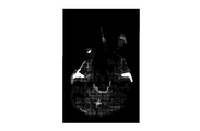
- FIG. 2A is a diagram showing an example of an MRI diagnostic image showing spatial distortion, which is generated by using Echo Planar Imaging (EPI) in a conventional MRI system without using parallel imaging.
- FIG. 2B is a diagram illustrating an example of a deployment artifact that is seen when the distortion of an EPI image is resolved in a conventional parallel imaging MRI system.
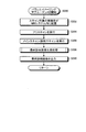
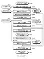
- FIG. 3 is a flowchart of a method for generating an image with reduced development artifacts due to a signal causing a spatial misalignment according to the present embodiment.
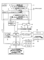
- FIG. 4 is a flowchart of a method for processing main scan data using an improved sensitivity map and an improved mask according to the present embodiment.
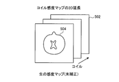
- FIG. 5A is a diagram illustrating a schematic diagram illustrating extension of the sensitivity map according to the present embodiment.
- FIG. 5B is a diagram illustrating a schematic diagram illustrating the extension of the sensitivity map according to the present embodiment.
- FIG. 5C is a diagram illustrating a schematic diagram illustrating the extension of the sensitivity map according to the present embodiment.
- FIG. 6A is a diagram showing an example of the prior art for extending the sensitivity map.
- FIG. 6B is a diagram showing an example of an error that can be caused by extending the sensitivity map by the conventional method.
- FIG. 7 is a diagram showing a technique for extending the sensitivity map according to the present embodiment.
- FIG. 8 is a flowchart of a method for processing main scan data using an improved sensitivity map according to the present embodiment.
- FIG. 9 is a flowchart of a method for processing main scan data using an improved mask according to the present embodiment.
- FIG. 10 is a flowchart of a method of using an improved sensitivity map and an improved mask according to this embodiment in combination with 2D phase correction in EPI.
- MRI Magnetic Resonance Imaging
- FIG. 1 is a high-level schematic block diagram of an MRI system adapted to reduce deployment artifacts due to spatially misaligned signals according to this embodiment.
- the MRI system shown in FIG. 1 includes a gantry 10 (shown in schematic cross section) and various associated system components 20 connected thereto. At least the gantry 10 is usually arranged in a shield room. Structure of the MRI system shown in Figure 1, a substantially static magnetic field B 0 magnet 12 arranged in a cylindrical coaxial, Gx, Gy, and the gradient coils 14 of Gz, a large whole body RF (radio frequency : RF) coil (Whole Body RF Coil: WBC) 16.
- RF radio frequency
- a small array RF coil (AC) 19 may be coupled within the imaging volume 18 closer to the patient's head (hereinafter referred to as “scanning object” or the like).
- small coils and / or array coils such as surface coils, as compared to whole body coils (WBCs) can be used for certain body parts (eg, arms, shoulders, Elbow, wrist, knee, leg, chest, spine, etc.)
- Array Coil AC
- PAC phased array coil
- the MRI system controller 22 has an input / output port connected to a display 24, a keyboard 26, and a printer 28.
- the display 24 may be of a touch screen type so as to allow control input.
- the MRI system controller 22 is connected to an MRI sequence controller 30, which includes Gx, Gy, and Gz gradient coil drivers 32, as well as an RF transmitter 34 and a transmit / receive switch (T / R) 36 ( Control when the same RF coil is used for both transmission and reception).
- the MRI sequence controller 30 includes a suitable program code structure 38 for implementing MRI imaging (also known as Nuclear Magnetic Resonance (NMR) imaging) techniques including parallel imaging. In parallel imaging, the MRI sequence controller 30 prepares a pre-scan sequence used to determine the sensitivity map of the whole body RF coil 16 and / or the array RF coil 19, and a scan sequence for acquiring a diagnostic image. Can be easily done.
- MRI imaging also known as Nuclear Magnetic Resonance (NMR) imaging
- the MRI system includes an RF receiver 40 that sends input to the MRI data processor 42 to create processed image data for display on the display 24.
- the MRI data processor 42 also includes a previously generated coil sensitivity map (hereinafter also referred to as sensitivity distribution), extended coil sensitivity map, mask data, and / or system configuration parameters 46, and MRI image reconstruction. Configured for access to program code structure 44 and program storage 50.
- FIG. 1 shows a general description of the program storage device 50 of the MRI system.
- the program storage 50 of the MRI system has stored program code structures (eg, for reducing deployment artifacts and reconstructing images, defining a graphical user interface, and receiving operator input thereto).
- the program storage 50 is segmented to provide at least a portion of the processing computer of the MRI system that requires such stored program code structure in normal operation with the highest priority. (I.e., not normally stored or directly connected to the MRI system controller 22).
- FIG. 1 shows a very high level schematic of a typical MRI system that has been modified to implement the exemplary embodiments described below.
- System components can be divided into “boxes” of various logical sets, usually with multiple digital signal processors (DSPs), microprocessors, and dedicated processing circuitry (eg, high-speed A / D). Conversion, fast Fourier transform, array processing, etc.).
- DSPs digital signal processors
- microprocessors eg, microcontrollers, microcontrollers, and dedicated processing circuitry (eg, high-speed A / D). Conversion, fast Fourier transform, array processing, etc.).
- Each of these processors is typically a clocked “state machine”, and the physical data processing circuit moves from one physical state to another every clock cycle (or a predetermined number of clock cycles). .
- the physical state of a processing circuit eg, CPU, register, buffer, computing device
- the physical state eg, magnetic
- Bit storage locations in the storage medium are also converted from one state to another during the operation of such a system.
- the array of storage locations of computer readable and accessible data values in the physical storage medium may have a certain prior state (e.g., all uniform To a new state, and the physical state of the physical location in such an array changes between the minimum and maximum values, resulting in real-world physics Events and physical conditions (eg, internal physical structures within the imaging volume space).
- such an array of stored data values is read sequentially into the instruction register and, when executed by one or more CPUs of the MRI system, a particular sequence of operating states within the MRI system. It represents and constitutes a physical structure, similar to a computer control program code of a particular structure that causes and transitions
- the exemplary embodiments described below provide an improved method for generating and displaying MR images.
- the MRI system includes an MRI sequence controller 30 and an MRI system controller 22.
- the MRI sequence controller 30 executes a pre-scan that collects the sensitivity distribution of the coil as a pre-scan unit.
- the MRI sequence controller 30 executes a main scan for collecting magnetic resonance image signals as a main scan unit.
- the MRI system controller 22 corrects the sensitivity distribution based on the distortion included in the magnetic resonance image by executing the main scan.
- the MRI system controller 22 generates an output magnetic resonance image (output image) by using the corrected sensitivity distribution as a generation unit.
- An MRI image is formed by acquiring an RF response value (for example, echo data) for a point in k-space.
- the RF response value is generated by traversing k-space two-dimensionally or three-dimensionally according to a set pulse sequence.
- Acquisition of echo data in the frequency encoding direction is usually fast and is on the order of a few milliseconds.
- each point is sampled with a different value of the applied phase encoding field gradient along the phase encoding direction (eg, y-axis). Therefore, usually, the acquisition time of the MRI image is mainly determined by the number of phase encoding steps.
- Non-Patent Document 1 describes a parallel imaging and reconstruction technique, the contents of which are incorporated herein in their entirety by reference. Another example of parallel imaging and reconstruction technology is SPEEDER® available in Toshiba's MRI system. However, parallel imaging may cause reconstruction artifacts in the output diagnostic image.
- the reconstruction artifact is mainly the unfolding required to obtain the desired diagnostic image based on the intermediate image obtained by undersampling (to reduce the image reconstruction area) in the phase encoding direction. Due to processing. “Development” is a process of combining a plurality of folded images in order to generate a desired diagnostic image. In many cases, the multiple folded images differ from each other in that each is collected from a different RF receiver coil. When two or more folded images are expanded, various artifacts may occur. Artifacts resulting from such expansion processing are referred to herein as “development artifacts”.
- MRI Magnetic resonance Imaging
- EPI Echo Planar Imaging
- the application of EPI in a high magnetic field has an advantage that a complete 2D (two-dimensional) image can be acquired by one imaging.
- Acquiring a complete image in a single shot includes, for example, diffusion (Diffusion Weighted Imaging (DWI), etc.), functional MRI (Functional MRI: FMRI), and perfusion (dynamic susceptibility contrast ( Dynamic Susceptibility Contrast (DSC) enhancement method or arterial spin labeling (Arterial Spin Labeling: ASL) is very desirable, but EPI is, for example, susceptibility, chemical shift, imperfect magnetic field uniformity adjustment and vortex Disadvantages include large distortions associated with current, and traditional acquisition encoding and reconstruction can cause spatial misalignment of these distortions, especially when traversing k-space with a fast zigzag pattern.
- diffusion Weighted Imaging DWI
- FMRI Functional MRI
- DSC Dynamic Susceptibility Contrast
- ASL arterial spin labeling
- EPI is, for example, susceptibility, chemical shift, imperfect magnetic field uniformity adjustment and vortex Disadvantages include large distortions associated with current, and traditional acquisition encoding and reconstruction can cause spatial
- Axial direction (eg, phase encoding direction) is slower than x direction (eg, frequency encoding direction) Crossing.
- x direction e.g., frequency encoding direction
- Crossing e.g., a phase encoding direction
- the second gradient magnetic field is much weaker than the first magnetic field gradient and thus becomes more that a large strain occurs along the phase encoding direction.
- the coil calibration pre-scan image also contributes to the final diagnostic image.
- the pixels are folded.
- the MR signal may be displaced (or shifted) before performing anti-aliasing compared to the corresponding coil calibration scan image (or corresponding coil sensitivity map). . If this defect is not solved, the development artifact may appear in the final diagnostic image.
- FIG. 2A shows an example of an MRI diagnostic image showing spatial distortion, which is generated by using Echo Planar Imaging (EPI) in a conventional MRI system without using parallel imaging.
- FIG. 2A shows an EPI image acquired without using parallel imaging and showing severe misalignment.
- the phase encoding is the front-back direction of the head (eg, the y-direction) and is shown as the up-down or vertical direction in the image.
- FIG. 2B shows an example of a deployment artifact that can be seen when the distortion of an EPI image is resolved in a conventional parallel imaging MRI system.
- FIG. 2B shows an EPI image of the head similar to FIG. 2A, which was acquired using parallel imaging.
- the distortion in the EPI is a distortion in which the masking from the sensitivity map as conventionally performed does not coincide with the position of the EPI signal. For example, if there is a region in the distorted EPI image that has important signals that extend outside the conventional mask, such as the signal for the right eye in FIG. 2A, the signal is placed in the wrong position due to parallel imaging matrix inversion.
- artifact 202 should be on the eye and roughly in the same position as the extreme distortion in FIG. 2A. However, as shown here, the overall distortion can be greatly reduced by the parallel imaging by the same factor value as the acceleration factor value for image acquisition. Here, in these images, the factor value is about 3. Note that a signal that has been developed in error can take a positive or negative value depending on the background phase difference. In particular, artifact 202 appears to be a relatively strong signal relative to other signals in the image, which can make it very difficult to accurately interpret the image from a diagnostic standpoint.
- Parallel imaging technology has two features that cause this incorrect reconstruction and aliasing.
- the distortion in the main scan is outside the mask formed from the conventional coil sensitivity map. Because it is outside the mask, the distorted signal is forcibly placed elsewhere in the reconstructed image, such as the location of another folded pixel.
- the second feature that causes incorrect reconstruction is that the sensitivity value used for the distorted signal is incorrect.
- This sensitivity value is determined from, for example, a corresponding coil sensitivity map. Due to incorrect values in the corresponding coil sensitivity map, improper encoding values can be used in the deployment. Errors in the coil sensitivity map may be caused by extrapolating the measured coil sensitivity.
- a local coil sensitivity value having a large error is selected. Can occur. If there is an error in the assumed encoding, an error will occur in the subsequent expansion step, and correspondingly, the final expansion image will contain errors and artifacts.
- Techniques for reducing deployment artifacts disclosed herein include techniques for processing coil sensitivity maps and techniques for processing masks used during deployment. A combination of improved techniques for processing coil sensitivity maps and improved techniques for processing masks can provide better results, but in some embodiments to generate improved diagnostic images. One of these techniques may be used.
- the technology for processing the coil sensitivity map in the pre-scan disclosed in the present specification detects the boundary line of the subject to be scanned, and then copies the sensitivity data outward so that the sensitivity map is positioned most particularly.
- a sensitivity map that more accurately reflects the actual coil sensitivity at the turning point in k-space is obtained compared to conventional coil sensitivity map generation. It is done.
- a sensitivity map is generated based on extrapolation of measured sensitivity data using a fitting polynomial corresponding to each RF coil in the array of RF coils.
- the technique for processing one or more masks disclosed in the present specification includes a step of generating one or more masks from a pre-expansion of a main scan.
- the advance development is a process of generating an intermediate diagnostic image in order to generate a mask, for example.
- the mask created from the preceding development of the main scan image displays the area of the important signal better, for example, with significantly improved accuracy compared to the conventional mask created based on the coil sensitivity map.
- the mask from the predevelopment has the same geometric distortion as the main scan, so using it does not improperly mask the signal in the critical area in the main scan, It is not forcibly arranged in other folded pixels.
- Conventional distortion correction techniques such as PLACE (phase-based correction technique) and so-called blip-up-blip-down techniques have required a significant increase in the number of acquisitions (for example, twice).
- PLACE phase-based correction technique
- blip-up-blip-down techniques have required a significant increase in the number of acquisitions (for example, twice).
- deployment artifacts can be reduced or substantially eliminated without increasing the number of acquisitions.
- artifacts are corrected without variations in the new series of images that may interfere with FMRI, DSC, or ASL processing.
- the disclosed embodiments can use conventional pre-scan techniques including techniques used for parallel imaging scans other than EPI.
- the technology disclosed herein is highly compatible with parallel programming and speeding up operations because it does not require conditions for creating different sized matrices or including different subsets of pixels. Provide the model.
- FIG. 3 is a flowchart of a method for generating an image with reduced development artifacts caused by a signal causing spatial misalignment according to the present embodiment.
- the parallel imaging subroutine A includes steps S302 to S310.
- steps S302 to S310 may not be executed or may be executed in an order other than that illustrated.
- the MRI system starts a parallel imaging subroutine A (step S300).
- the subject to be scanned is placed in the MRI system (step S302).
- This operation includes setting up an MRI system that executes a scan sequence suitable for acquiring a desired type of diagnostic image in addition to placing the subject in the gantry 10 in a manner suitable for scanning.
- Settings may include selection of pre-scan sequences and main scan sequences, attenuation factors associated with parallel imaging, tilt settings, and the like.
- the MRI sequence controller 30 performs a pre-scan that collects the sensitivity distribution of the coil as a pre-scan unit (step S304).
- a pre-scan of the subject in the gantry 10 By performing a pre-scan of the subject in the gantry 10, a coil sensitivity map is generated for a plurality of RF coils.
- the pre-scan can be executed within a settable time, which is usually about several seconds and is substantially shorter than the main scan.
- pre-scanning a low-resolution image is obtained for all the imaging volumes in the scanner (in this case, the subject arranged inside).
- Patent Document 1 describes one or more prescan techniques, which are incorporated herein in their entirety by reference.
- any of a plurality of pre-scan techniques including a high-speed 2D gradient recalled echo pulse sequence described in Patent Document 1 may be used.
- a 2D or 3D Fourier transform field echo scan may be performed (eg, it may take about 20 seconds in some cases).
- the pre-scan may include generating a coil sensitivity map (these are also referred to as “spatial sensitivity map” or “sensitivity distribution”) from the data acquired in the pre-scan.
- the coil sensitivity map may be determined using a technique selected from the techniques described in Non-Patent Document 1 or Patent Document 1.
- Patent Document 1 describes one or more techniques for determining the coil sensitivity of each coil, and may be used to create a sensitivity map for a coil array.
- the ratio of the prescan image luminance of each coil and the sum of the prescan image luminances of all the coils are calculated for each pixel.
- the technique described in Patent Document 1 does not require a WBC calibration image.
- the spatial sensitivity of each coil may be determined by distributing each pre-scan image to the whole body coil image by other techniques. These techniques remove noise (eg, patient effects on the measurement signal) due to the pre-scan image that provides the coil sensitivity map and define a spatial sensitivity map for each RF coil in the phased array coil.
- a coil sensitivity map may be stored for use in association with one or more subsequent main scans.
- the MRI sequence controller 30 performs a main scan as a main scan unit for collecting magnetic resonance image signals (step S306). For example, a main scan of a subject placed on the gantry 10 is executed. The type of main scan and the sequence of images to be acquired may be settable. For example, in one embodiment, EPI is executed as the main scan. In the parallel imaging technique, since all the coils in the phased array coil receive signals simultaneously, a spatial sensitivity map of each coil is necessary to recover an image without folding from the folded image of each coil. Data received from the main scan (main scan data) is also referred to herein as one or more intermediate diagnostic images.
- the MRI system controller 22 executes a final diagnostic image generation process (step S308).
- main scan data eg, an intermediate diagnostic image
- This process includes developing an intermediate diagnostic image using a coil sensitivity map and / or mask improved according to embodiments described herein.
- the deployment artifacts that the final diagnostic image has are greatly reduced compared to conventional parallel imaging scans.
- a plurality of final diagnostic images may be generated.
- any of parallel imaging subroutines B to E described later is executed (see FIGS. 4 and 8 to 10).
- a final diagnostic image (output image) is output (step S310).
- This output may include displaying on the display of the MRI system or on an external display.
- this output is transmitted through a network interface that may be part of the MRI system, or is embedded in or communicably coupled to the MRI system. The process of storing in any one of these memories or another memory
- storage device may be included.
- FIG. 4 is a flowchart of a method of processing a main scan using an improved sensitivity map and an improved mask according to the present embodiment.
- the parallel imaging subroutine B includes steps S410-426. However, depending on the embodiment, one or more of steps S410-426 may not be performed, or may be performed in an order other than illustrated. According to one embodiment, steps S410-426 are performed in the process of step S308 described above.
- the MRI system starts a parallel imaging subroutine B (step S400).
- the MRI system controller 22 specifies a position slightly inside the boundary line (peripheral part or the like) of the subject (step S410).
- a coil sensitivity map such as the coil sensitivity map generated by the process of step S304 described above is processed to determine the boundary line (for example, the peripheral edge) of the subject to be scanned.
- the input coil sensitivity map 402 is referred to as a “raw coil sensitivity map”, reflecting that these maps have not yet been extended.
- some embodiments may use a coil sensitivity map for which some further processing may have already been performed.
- the boundary line of the subject to be scanned may be detected by using a conventional boundary line finding technique using 2D display (for example, a transverse slice image) of the subject.
- 2D display for example, a transverse slice image
- a series of points that are slightly inside the boundary line are determined.
- the exact distance from the selected series of points to the boundary can be set.
- the selected point may be a configurable number of pixels inside the border, or may be a measurement of a configurable distance inside the border (eg millimeters or centimeters) It may be within a settable distance range (for example, 0.5 to 1.5 cm).
- not all of the selected series of points are at the same distance from the boundary.
- the initially indicated selection point may not have a value that is sufficiently accurate to indicate actual coil sensitivity. It is. For example, if the position of the first indicated point is very close to the bone or cavity (depending on the set distance range), the first indicated position remains within the set distance range and Modifications may be made to move away from bone or cavity areas that may cause inaccurate sensitivity values in the surrounding area.
- the MRI system controller 22 replicates each point at the specified position in the phase encoding direction (step S412). That is, the MRI system controller 22 corrects the sensitivity distribution as a correction unit based on the distortion included in the magnetic resonance image by executing the main scan. For example, the boundary line of the subject in the coil sensitivity map is extended. In particular, each point from the series of points identified in step S410 is replicated to a settable distance away from the boundary, at least in the phase encoding direction of the main scan.
- the reason for duplicating in the phase encoding direction is, for example, that the most error is expected, and this duplication is in contrast to extrapolation by curve fitting.
- the points may be duplicated up to the edge of the field of view (FOV) in either direction along the phase encoding direction.
- FOV field of view
- the MRI system controller 22 obtains a direction for expanding or reducing the sensitivity distribution based on the direction of distortion included in the magnetic resonance image, and corrects the sensitivity distribution as a correction unit. Specifically, the MRI system controller 22 corrects the sensitivity distribution by expanding or reducing the sensitivity distribution by duplication. More specifically, the MRI system controller 22 replicates a point inside the boundary line corresponding to the subject in the sensitivity distribution in the direction of phase encoding as replication.
- the distortion is distortion in which distortion generated along the phase encoding direction in the k space appears in the magnetic resonance image.
- FIGS. 5A-5C Example of duplication is shown in FIGS. 5A-5C.
- 5A to 5C are schematic diagrams showing the extension of the sensitivity map according to the present embodiment.
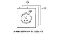
- the raw or uncorrected sensitivity map 502, such as that acquired by each coil, is accessed in the memory or storage of the MRI system.
- Each of the raw sensitivity maps 502 is analyzed to identify the outer boundary line 504.
- FIG. 5A shows a raw sensitivity map 502 with identified boundaries 504.
- a series of points at position 506 are identified slightly inside the boundary as shown in FIG. 5B.
- a peripheral portion that is relatively close to the specified boundary line is specified.
- the head scan identifies a series of points 1 cm inside the boundary.
- FIG. 5B a series of points 1 cm inside the boundary.
- the points 508 and 510 from the series of points at the identified position 506 are in the extending directions 512 and 514 where misalignment is likely to occur.
- the direction in which misalignment is likely to occur is the phase encoding direction associated with the main scan. This extension direction does not necessarily coincide with the phase encoding direction of the sensitivity map of the prescan.
- Each point in the extension directions 512 and 514 is realized by duplicating the points 508 and 510.
- the extension of points by duplication in this embodiment is in contrast to the prior art, which generally extended the sensitivity map by extrapolation by fitting the spatial polynomial curve of each coil.
- the preferred extension of the points 508 and 510 in the phase encoding direction in this embodiment is in contrast to the prior art which extends the boundary line in various (eg, probably all) directions according to the polynomial curve fit of each coil. is there.
- FIG. 6A shows an example of the prior art for extending the sensitivity map.
- FIG. 6B shows an example of an error that can be caused by extending the sensitivity map by the conventional method.
- FIG. 7 shows a technique for extending the sensitivity map according to the present embodiment.
- FIG. 6A shows a conventional technique for extending the boundary line of a scanned object by extrapolation.
- FIG. 6B shows an example of errors that can be caused by such prior art extending the sensitivity map.
- FIG. 7 illustrates the extension of the sensitivity map by duplication according to an exemplary embodiment. 6A-B and FIG. 7, it is assumed that the physical phase encoding direction is along the horizontal (left-right) direction. The vertical direction in these small schematic diagrams can be considered as the signal strength axis.
- FIG. 6A shows the extension of the coil sensitivity value according to the prior art.
- a boundary line 602 of the subject to be scanned is determined.
- the area within the detected boundary is considered to have a reliable measurement coil sensitivity value.
- a curve fitting polynomial is determined for each coil sensitivity of the array based on the value of the point inside the detected boundary line.
- the polynomials 604 and 606 representing the coil sensitivities of coil 1 and coil 2 of the array, respectively, correspond to the value of the corresponding point in the region surrounded by the detected boundary line 602. Determined to fit.
- polynomials 604 and 606 may be determined by any of the well-known polynomial fitting techniques.
- the prior art extrapolates each of the polynomials 604 and 606 to regions 610 and 612 outside the detected boundary.
- the prior art extrapolates each of the polynomials 604 and 606 to regions 610 and 612 outside the detected boundary.
- FIG. 6B shows how a signal with spatial misalignment as generated in EPI can cause a significant error when the conventional extension technique is applied.
- Coil sensitivity values 632 and 634 (and the EPI signal level associated with the image enhanced by the same sensitivity) within the detected boundary 620 of the object are considered to be shown at the true or correct signal position. sell.
- Values 626 and 628 at the position of the signal that shows the coil sensitivity (or sensitivity-enhanced main image (EPI) pixel signal value) but are misaligned may appear near the correct sensitivity values 632 and 634, respectively. is there. If the actual coil sensitivity is extended based on extrapolation of the corresponding polynomial, a relatively large error may occur.
- the magnitude of the error due to the misalignment between the misaligned signal 628 and the corresponding true signal 634 inside the scanned subject boundary 620 is the position corresponding to the developed position 638. As indicated by 640 indicating the difference from the misaligned position 634, it can be quite large when reconstructing the image.
- the corresponding signals are encoded using coil sensitivity values 634 and 632.
- the corresponding coil sensitivities used during reconstruction deployment are coil sensitivity values 638 and 636, respectively.
- These coil sensitivity values outside the detected boundary 620 of the subject are determined based on a polynomial that fits the coil sensitivity value of each coil.
- the error 640 between the coil sensitivity 638 used during reconstruction and the coil sensitivity 634 that actually encodes the signal is due to the specific misalignment of the signal and the corresponding actual error. It appears to be considerably larger than.
- One reason for the relatively large error between 634 and 638 is that the data is extrapolated from the inside to the outside of the detected boundary according to a polynomial by curve fitting corresponding to the coil sensitivity of each coil. Can be mentioned.
- FIG. 7 illustrates a point from the inside to the outside of the detected boundary line 650 (eg, coil sensitivity) by duplicating the corresponding value to the region extended from the inside of the detected boundary line, according to one embodiment.
- the extension (replication) of the value) is illustrated.
- the sensitivity map of coil 1 includes sensitivity 654 in the area inside the detected boundary and sensitivities 658 and 662 in the extended area.
- the sensitivity map of coil 2 includes sensitivity 652 in the region inside the detected boundary and sensitivities 656 and 664 in the extended region.
- the MRI system controller 22 generates a sensitivity encoding matrix (also simply referred to as a sensitivity matrix) (step S414).
- a sensitivity encoding matrix is formed using a sensitivity map extended by duplication.
- the sensitivity encoding matrix can be determined using a technique disclosed in Non-Patent Document 1 and Patent Document 2.
- the folded pixel position is indicated by.
- the value of the matrix at position (i, j) indicates the sensitivity for the jth pixel when received at coil i.
- each element of the sensitivity matrix can be determined from the sensitivity map acquired during the prescan. For this reason, before extending the sensitivity map as in step S412, the sensitivity map includes the measured sensitivity value. After extension by replication, the sensitivity matrix may include values based on the extension.
- the MRI system controller 22 inverts the sensitivity encoding matrix to generate a decoding matrix (step S416).
- the decoding matrix allows data to be converted back from a plurality of coils specified in the sensitivity matrix to a plurality of unfolded pixels.
- the inversion may be by a well-known matrix inversion technique such as a Moore-Penrose pseudo-inverse matrix. This is, for example, a closed-form solution of the least-squares method with a minimum noise condition on the premise of uniform uncorrected noise in a simple form. If necessary, correction of the receiver noise level and noise in the receiver channel can be used in determining the inverse of the sensitivity matrix as described in Non-Patent Document 1.
- inversion may or may not take into account receiver noise levels and corrections.
- SNR signal-to-noise ratio
- the MRI system controller 22 expands the main scan data 404 (step S418).
- the development of the main scan data is executed using the decoding matrix generated in step S416.
- the expansion in step S418 is performed without using a mask.
- the mask indicates which data points in the image can be ignored because they are outside the region of interest (ROI).
- the expansion in step S418 includes the use of a mask formed based on a coil sensitivity map or coil sensitivity matrix.
- a mask formed based on a coil sensitivity map or coil sensitivity matrix indicates which pixel locations are inside the region of interest and which are outside, and using such information, By simply considering pixel locations that are inside and / or near the ROI, the quality of the unfolding process can be improved.
- Non-Patent Document 1 describes that the size of the sensitivity map can be reduced by removing the folding point where there is no signal, and that the degree of freedom to minimize noise can be increased if a constrained and smaller system can be handled. Has been.
- Patent Document 4 of King et al. Describes a technique for reducing noise with some loss of signal fidelity by improving the sensitivity matrix and adding a regularization term to matrix inversion processing. Which is incorporated herein by reference in its entirety. Conventionally, the points to be excluded or not emphasized are identified by using a pre-scan sensitivity map because they do not have aliasing.
- a technique for developing main scan data (image) using a decoding matrix is well-known, and a technique such as that described in Non-Patent Document 1 is used to make main scan data using a decoding matrix as described above.
- the diagnostic image developed from can be acquired.
- the diagnostic image developed at this stage is called an intermediate diagnostic image.
- the MRI system controller 22 generates a mask from the main scan data (intermediate diagnostic image) developed in step S418 (step S420).
- the mask can be determined based on a threshold function that identifies that a particular pixel or region has a pixel brightness lower than the required pixel brightness.
- the required pixel brightness may be settable.
- the mask is intended to indicate which image data points are outside the ROI and can be ignored.
- the mask allows the pixel to be excluded from consideration in the reconstruction when the corresponding position in the scanned subject does not contribute to the signal, for example because it is outside the subject or ROI. In general, by removing pixels that are unlikely to contribute to reconstruction, the degree of aliasing can be reduced, resulting in improved SNR.
- Pixel exclusion from the encoding matrix can be done as a whole using a matrix with the columns removed, or it can be partially resized by multiplying a small value to de-emphasize the columns. And pixels can be excluded. If the column is unemphasized and not specifically excluded, the matrix inversion of the same size can be performed for all series of folded pixels, and the algorithm may be applied to computational parallel processing.
- the MRI system controller 22 generates the intermediate magnetic resonance image by performing the first unfolding process on the signal obtained by the parallel imaging as the mask generation unit by the processes of steps S418 and S420. A mask or weighting information is generated using the generated intermediate magnetic resonance image.
- the MRI system controller 22 generates an improved sensitivity encoding matrix using the mask generated in step S420 (step S422).
- the columns in the sensitivity matrix indicate the location of the folded pixels.
- one or more columns in the sensitivity matrix that correspond to pixel locations that do not contribute to the signal or that are outside the ROI may be removed.
- the MRI system controller 22 inverts the improved sensitivity map to generate an improved decoding matrix (step S424).
- the processing in step S424 may be performed in the same manner as in step S416, but based on the improved sensitivity matrix.
- the improved sensitivity matrix can be inverted with or without taking receiver noise into account.
- the MRI system controller 22 develops the main scan data 404 using the improved decoding matrix (step S426).
- the process of step S426 may be performed in the same manner as step S418 based on the improved decoding matrix.
- the output image of the main scan is reconstructed.
- the MRI system controller 22 uses the sensitivity distribution of each coil obtained by pre-scanning, the signal obtained by parallel imaging, and the mask or weighting information as a generation unit by the processing of steps S422 to S426.
- an output magnetic resonance image is generated by performing the second unfolding process.
- the MRI system controller 22 generates an output magnetic resonance image using the corrected sensitivity distribution as a generation unit.
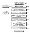
- FIG. 8 is a flowchart of a method for processing a main scan using an improved sensitivity map according to the present embodiment.
- FIG. 8 shows a flowchart for processing main scan data using the improved sensitivity map according to the present embodiment.
- the parallel imaging subroutine C includes steps S806-814.
- steps S806 to S814 may not be executed, or may be executed in an order other than that illustrated.
- steps S806-814 are performed during the process of step S308 above.
- a diagnostic image may be generated using the improved sensitivity map disclosed herein, but the use of the improved mask disclosed herein is not required.
- the MRI system starts a parallel imaging subroutine C (step S800).
- An unwrapped raw sensitivity map 802 is provided as an input to step S806.
- the raw sensitivity map 802 may be a sensitivity map acquired from the receiving coil.
- the processing in steps S806 to S812 may be performed in the same manner as the corresponding processing in steps S410 to S416 described above. If necessary, in the process of step S810, in addition to the process described with respect to step S414, a mask generated based on the sensitivity map or the sensitivity matrix may be considered when generating the sensitivity encoding matrix. The use of masks in creating the decoding matrix has been described above in connection with other operations.
- the MRI system controller 22 develops the main scan data 804 using the decoding matrix generated in the process of step S812 (step S814).
- the main scan data 804 may be a folded image.
- FIG. 9 is a flowchart of a method for processing main scan data using an improved mask according to the present embodiment.
- FIG. 9 shows a flowchart of a parallel imaging subroutine D according to the present embodiment, which processes main scan data using an improved mask.
- the parallel imaging subroutine D includes steps S906-918.
- steps S906 to S918 may not be executed or may be executed in an order other than that illustrated.
- steps S906 to 918 are performed in the process of step S308 described above.
- a diagnostic image may be generated using the improved mask disclosed in the present specification, but the use of the improved sensitivity map disclosed in the present specification is not required.
- the MRI system starts a parallel imaging subroutine D (step S900).
- An unwrapped raw sensitivity map 902 is provided as an input to step S906.
- the raw sensitivity map 902 may be a sensitivity map acquired from the receiving coil.
- a sensitivity matrix is generated based on the sensitivity map.
- the sensitivity map is used without further processing to extend the map beyond the boundary of the subject.
- the map may be extended in step S906 so as to exceed the boundary line of the subject.
- the extension may be based on an extrapolation of known (eg, measured) sensitivity values. For example, the extrapolation may follow prior art as described above with respect to FIG. 6A, but preferably uses an extension technique by duplication as described above with respect to FIG.
- the MRI system controller 22 creates a decoding matrix by inverting the sensitivity matrix generated using the sensitivity map (step S908).
- the sensitivity map may or may not be extended. The generation of the sensitivity matrix and the decoding matrix has been described above.
- the MRI system controller 22 develops the main scan data 904 using the decoding matrix (step S910).
- the MRI system controller 22 generates a mask based on the main scan data developed in step S910 (step S912). Development and mask generation have been described above with reference to FIG.
- the MRI system controller 22 generates an improved sensitivity encoding matrix using the mask generated in step S912 (step S914), and the sensitivity matrix is processed.
- An improved sensitivity matrix may be generated by removing or weakening pixel locations that either do not provide a signal or are outside the region of interest in a manner similar to that described above with respect to step S422. .
- the MRI system controller 22 inverts the improved sensitivity encoding matrix generated by the process of step S914, and generates an improved decoding matrix (step S916).
- the MRI system controller 22 develops the main scan data 904 using the improved decoding matrix from the process of step S916 (step S918).
- FIG. 10 is a flowchart of a method of using the improved sensitivity map and the improved mask according to the present embodiment in combination with 2D phase correction in EPI.
- FIG. 10 shows a flowchart using an improved sensitivity map in combination with an improved mask according to this embodiment in combination with 2D phase correction in EPI.
- the parallel imaging subroutine E includes steps S1022 to S1050. However, depending on the embodiment, one or more of steps S1022 to S1050 may not be executed, or may be executed in an order other than illustrated. According to one embodiment, steps S1022 to S1050 are executed in the process of step S308 described above.
- the parallel imaging subroutine E uses 2D phase correction in EPI to combine an improved sensitivity map and an improved mask as disclosed herein.
- 2D phase correction is frequently used to remove Nyquist ghosts in EPI images.
- Non-Patent Document 2 describes 2D phase correction in EPI.
- method step S1000 illustrates the use of an improved sensitivity map and an improved mask as disclosed herein, along with correction of 2D Nyquist low spatial frequency ghosts.
- the MRI system starts a parallel imaging subroutine E (step S1000).
- the MRI system controller 22 extends the coil sensitivity map 1002 in the phase encoding direction (step S1022).
- the extension of the coil sensitivity map 1002 includes the steps of identifying the position of the sensitivity map or region on the pre-scan image slightly inside the subject's boundary, and the phase encoding direction. Extending the identified pixels by duplication.
- the extended sensitivity map 1008 may be held in a memory.
- the MRI system controller 22 receives the EPI Nyquist pre-scan data 1004 as an input, and generates separate reference images for even and odd numbers using a 2D Fourier transform (2DFT) (step S1024).
- This EPI Nyquist pre-scan data 1004 is also known as an “EPI template”.
- the EPI template may be acquired in a prescan different from the prescan for acquiring the sensitivity map.
- the MRI system controller 22 determines the phase difference between the even row image and the odd row image using the odd and even reference images (step S1026).
- the MRI system controller 22 accumulates the phase differences over a plurality of channels with or without additional processing, adds the signals of the plurality of channels, obtains the phase in arctangent from the signal values of the real part and the imaginary part (ATNA) (step S1028). ), A Nyquist correction map 1010 is generated. In some embodiments, the Nyquist correction map 1010 identifies the multiplicative composite phase map required to remove the Nyquist ghost.
- the MRI system controller 22 selects a reference MRI data acquisition shot from the image of the EPI main scan 1006 (step S1030).
- the MRI system controller 22 determines even and odd 2DFT image data for mask generation based on the selected reference image (step S1032).
- the MRI system controller 22 receives as input the even and odd 2DFT image data, the Nyquist correction map 1010, and the extended sensitivity map 1008 determined in step S1032, and generates an intermediate EPI image 1036 (step S1034).
- the processing in step S1034 may include a step of encoding a sensitivity matrix, a step of generating a decoding matrix by inverting the sensitivity matrix, and a step of developing an EPI image using the decoding matrix.
- the EPI image 1036 is suboptimal in the sense that it can have a high g value.
- the MRI system controller 22 identifies the position of the pixel whose luminance value is less than the threshold based on the sub-optimal EPI image 1036 (threshold processing) (step S1038).
- the threshold value may be set or dynamically determined. These positions may be non-emphasized maps in which the emphasis of each position becomes smaller as the position expands from the scanned object. As a result, a mask or non-emphasized map 1012 is determined using pixel locations identified as being less than the threshold.
- the non-emphasis map is an example of weighting information in which a luminance value is weighted according to the pixel position.
- the MRI system controller 22 determines even and odd 2DFTs for all the EPI main scan images 1006 (step S1040). Next, the MRI system controller 22 considers the even and odd 2DFT image data obtained from each of the EPI main scan images 1006 together with the mask 1012, the Nyquist correction map 1010, and the extended sensitivity map 1008. The final EPI image 1050 with the g value reduced to a desired value is generated (step S1042). Note that the process of step S1042 includes a process of encoding a sensitivity matrix, a process of generating a decoding matrix, and a process of developing an EPI image using the decoding matrix, as in the process of step S1034.
- the final EPI image is subjected to partial k-space homodyne filtering correction (Partial K-Space Homodyne Filtering Correction: PKH), high-frequency image uniformity correction (radio frequency Image Uniformity Correction: IUC), gradient distortion correction (Gradient Distortion Correction: GDC) ) And other post-processing functions.
- PKH Partial K-Space Homodyne Filtering Correction
- IUC Radio frequency Image Uniformity Correction
- GDC Gradient Distortion Correction
- the above embodiment is (A) a developed “intermediate” diagnostic image to generate a more accurate mask for use in further processing the raw image data to obtain a final developed diagnostic image; (B) Provides improved parallel MR imaging by using either or both of the coil sensitivity map extension by duplication (rather than extrapolation by curve fitting) used in final development of diagnostic images To do.
- the improved sensitivity map (sensitivity distribution) can be used for luminance correction.
- luminance correction is performed using a sensitivity distribution obtained by pre-scan (for example, reference scan).
- pre-scan for example, reference scan
- the obtained image is distorted, so that appropriate luminance correction can be performed using the sensitivity distribution obtained by the prescan.
- the image quality of the output image deteriorates.
- the MRI system according to the present embodiment performs luminance correction on the image obtained by EPI using the sensitivity distribution (for example, FIG. 7) according to the present embodiment.
- the MRI system performs luminance correction using the extended sensitivity distribution for the distorted image, so that the luminance correction can be performed appropriately and the image quality of the output image can be improved.
- the embodiment is not limited to this.
- the above-described problem is not limited to EPI, but may also occur when a pulse sequence is performed that reverses the polarity of the gradient magnetic field.
- the MRI system according to the embodiment is not limited to EPI, and may be applied when a pulse sequence in which the polarity of the gradient magnetic field is reversed is performed.
- a “regularization” process is used instead, a mask can be generated or not used.
- the image quality of the output image can be improved.
Landscapes
- Physics & Mathematics (AREA)
- Health & Medical Sciences (AREA)
- Condensed Matter Physics & Semiconductors (AREA)
- General Physics & Mathematics (AREA)
- Engineering & Computer Science (AREA)
- High Energy & Nuclear Physics (AREA)
- Nuclear Medicine, Radiotherapy & Molecular Imaging (AREA)
- Signal Processing (AREA)
- General Health & Medical Sciences (AREA)
- Radiology & Medical Imaging (AREA)
- Life Sciences & Earth Sciences (AREA)
- Biophysics (AREA)
- Biomedical Technology (AREA)
- Heart & Thoracic Surgery (AREA)
- Medical Informatics (AREA)
- Molecular Biology (AREA)
- Surgery (AREA)
- Animal Behavior & Ethology (AREA)
- Pathology (AREA)
- Public Health (AREA)
- Veterinary Medicine (AREA)
- Magnetic Resonance Imaging Apparatus (AREA)
Abstract
実施形態に係るMRIシステムは、MRIシーケンスコントローラ(30)と、MRIシステムコントローラ(22)とを備える。MRIシーケンスコントローラ(30)は、プリスキャン部として、コイルの感度分布を収集するプリスキャンを実行する。MRIシーケンスコントローラ(30)は、本スキャン部として、磁気共鳴画像の信号を収集する本スキャンを実行する。MRIシステムコントローラ(22)は、補正部として、前記本スキャンの実行により磁気共鳴画像に含まれる歪みに基づいて、前記感度分布を補正する。MRIシステムコントローラ(22)は、生成部として、前記補正後の感度分布を用いて、出力磁気共鳴画像を生成する。
Description
本発明の実施形態は、磁気共鳴イメージング装置に関する。
磁気共鳴イメージングは、静磁場中に置かれた被検体の原子核スピンを、そのラーモア(Larmor)周波数のRF(Radio Frequency)パルスで磁気的に励起し、励起に伴い発生する磁気共鳴信号のデータから画像を生成する撮像法である。磁気共鳴イメージングにおいて、高速に撮像するための技術や画質を向上させるための技術が種々提案されている。
K.P.Pruessmann他著、「SENSE:高速MRIのための感度エンコーディング法(Sensitivity Encoding for Fast MRI)」、磁気共鳴医学会(Magnetic Resonance in Medicine)、42巻、952~962ページ、1999年
D.Xu他著、「狭い撮像視野におけるエコープラナーイメージングのためのロバスト2D位相補正(Robust 2D Phase Correction for Echo-Planar Imaging Under a Tight Field of View)」、磁気共鳴医学会(Magnetic Resonance in Medicine)、64巻(6版)、1800~1813ページ、2010年12月
本発明が解決しようとする課題は、出力画像の画質を向上させることができる磁気共鳴イメージング装置を提供することである。
実施形態に係る磁気共鳴イメージング装置は、プリスキャン部と、本スキャン部と、補正部と、生成部とを備える。プリスキャン部は、コイルの感度分布を収集するプリスキャンを実行する。本スキャン部は、磁気共鳴画像の信号を収集する本スキャンを実行する。補正部は、前記本スキャンの実行により磁気共鳴画像に含まれる歪みに基づいて、前記感度分布を補正する。生成部は、前記補正後の感度分布を用いて、出力磁気共鳴画像を生成する。
以下、図面を参照して、実施形態に係る磁気共鳴イメージング装置(以下、適宜、MRI(Magnetic Resonance Imaging)システム)を説明する。
(実施形態)
図1は、本実施形態に係る、空間的位置ずれを起こした信号に起因する展開アーティファクトを低減するように適合させた、MRIシステムの高度な概略ブロック図である。図1に示すMRIシステムは、ガントリ10(概略断面で示す)と、これに接続された各種の関連システム構成要素20とを含む。少なくともガントリ10は、通常はシールドルーム内に配置される。図1に示すMRIシステムの構造は、実質的に同軸の円筒形に配置された静磁場B0磁石12と、Gx、Gy、及びGzの傾斜磁場コイル14と、大型の全身用高周波(radio frequency:RF)コイル(Whole Body RF Coil:WBC)16とを含む。この円筒形に配列された要素の水平軸に沿って、患者用寝台11によって支持された患者(被検体)9の頭部を実質的に取り囲むように示された、イメージングボリューム18がある。小型のアレイRFコイル(Array RF Coil:AC)19を、イメージングボリューム18内で患者の頭部(以後、「スキャン対象」等と呼ぶ)に、より近接して結合してもよい。当業者には明らかなように、表面コイル等のように、全身用コイル(Whole Body Coil:WBC)と比較して小さいコイル及び/又はアレイコイルは、特定の身体部分(例えば、腕、肩、肘、手首、膝、脚、胸、背骨等)に合わせて設計されることが多い。以後、そのような小型RFコイルを、アレイコイル(Array Coil:AC)又はフェーズドアレイコイル(Phased Array Coil:PAC)と呼ぶ。これらは、RF信号をイメージングボリューム内に送信するよう構成された少なくとも1つのコイルと、イメージングボリュームにおいて、上記の例における患者の頭部等の被検体からのRF信号を受信するよう構成された複数の受信コイルとを含んでもよい。
図1は、本実施形態に係る、空間的位置ずれを起こした信号に起因する展開アーティファクトを低減するように適合させた、MRIシステムの高度な概略ブロック図である。図1に示すMRIシステムは、ガントリ10(概略断面で示す)と、これに接続された各種の関連システム構成要素20とを含む。少なくともガントリ10は、通常はシールドルーム内に配置される。図1に示すMRIシステムの構造は、実質的に同軸の円筒形に配置された静磁場B0磁石12と、Gx、Gy、及びGzの傾斜磁場コイル14と、大型の全身用高周波(radio frequency:RF)コイル(Whole Body RF Coil:WBC)16とを含む。この円筒形に配列された要素の水平軸に沿って、患者用寝台11によって支持された患者(被検体)9の頭部を実質的に取り囲むように示された、イメージングボリューム18がある。小型のアレイRFコイル(Array RF Coil:AC)19を、イメージングボリューム18内で患者の頭部(以後、「スキャン対象」等と呼ぶ)に、より近接して結合してもよい。当業者には明らかなように、表面コイル等のように、全身用コイル(Whole Body Coil:WBC)と比較して小さいコイル及び/又はアレイコイルは、特定の身体部分(例えば、腕、肩、肘、手首、膝、脚、胸、背骨等)に合わせて設計されることが多い。以後、そのような小型RFコイルを、アレイコイル(Array Coil:AC)又はフェーズドアレイコイル(Phased Array Coil:PAC)と呼ぶ。これらは、RF信号をイメージングボリューム内に送信するよう構成された少なくとも1つのコイルと、イメージングボリュームにおいて、上記の例における患者の頭部等の被検体からのRF信号を受信するよう構成された複数の受信コイルとを含んでもよい。
MRIシステムコントローラ22は、ディスプレイ24、キーボード26、及びプリンタ28に接続された入力/出力ポートを有する。当然のことながら、ディスプレイ24は、制御入力もできるようにタッチスクリーンタイプのものでもよい。
MRIシステムコントローラ22は、MRIシーケンスコントローラ30に接続され、MRIシーケンスコントローラ30は、Gx、Gy、及びGzの傾斜磁場コイルドライバ32、ならびにRF送信機34及び送信/受信スイッチ(T/R)36(同じRFコイルが送信と受信の両方に使用される場合)を制御する。MRIシーケンスコントローラ30は、パラレルイメージングを含むMRIイメージング(核磁気共鳴(Nuclear Magnetic Resonance:NMR)イメージングとしても知られている)技術を実装するための適切なプログラムコード構造38を含む。パラレルイメージングでは、MRIシーケンスコントローラ30により、全身用RFコイル16及び/又はアレイRFコイル19の感度マップを決定するために用いられる準備スキャン(プリスキャン)シーケンス、及び診断画像を取得するためのスキャンシーケンスを容易にできる。
MRIシステムは、ディスプレイ24に表示する処理画像データを作成するために、入力をMRIデータプロセッサ42に送るRF受信機40を含む。また、MRIデータプロセッサ42は、前に生成されたコイル感度マップ(以下、感度分布とも表記する)、延長されたコイル感度マップ、マスクデータ、及び/又はシステム構成のパラメータ46、及びMRI画像再構成プログラムコード構造44及びプログラム記憶装置50へのアクセス用に構成される。
また、図1に、MRIシステムのプログラム記憶装置50の一般的説明を示す。MRIシステムのプログラム記憶装置50では、(例えば、展開アーティファクトを低減して画像再構成するためや、グラフィカルユーザーインタフェースを規定し、それに対する操作者の入力を受け取るための)格納されたプログラムコード構造が、MRIシステムの各種データ処理構成要素へアクセス可能な非一時的コンピュータ可読記憶媒体に格納される。当業者には明らかなように、プログラム記憶装置50をセグメント化して、少なくとも一部分を、MRIシステムの処理コンピュータのうち、通常操作においてそのような格納されたプログラムコード構造を最優先で必要とする別のコンピュータに直接接続してもよい(すなわち、MRIシステムコントローラ22に普通に格納したり直接接続したりするのではない)。
実際に、当業者には明らかなように、図1は、後述する例示的実施形態を実現するために変更された典型的なMRIシステムの、非常に高度な概略図を示したものである。システム構成要素は、様々な論理集合の「ボックス」に分割することができ、通常、多数のデジタル信号プロセッサ(Digital Signal Processor:DSP)と、マイクロプロセッサと、専用処理回路(例えば、高速A/D変換用、高速フーリエ変換用、アレイ処理等用)とを含む。これらのプロセッサの各々は、通常、クロック制御された「状態マシン」であり、物理データ処理回路は、クロックサイクル(又は、所定数のクロックサイクル)毎に、ある物理状態から別の物理状態に移る。
処理回路(例えば、CPU、レジスタ、バッファ、演算装置)の物理状態が、操作過程であるクロックサイクルから別のクロックサイクルに徐々に変化するだけでなく、関連データ記憶媒体の物理状態(例えば、磁気記憶媒体内のビット記憶場所)も、このようなシステムの操作過程において、ある状態から別の状態に変換される。例えば、画像再構成処理及び/又は時としてコイル感度マップ生成処理の終わりに、物理的記憶媒体内のコンピュータ可読でアクセス可能なデータ値の記憶場所の配列は、ある先行状態(例えば、全て一様に「0」値、又は全て「1」値)から新しい状態に変換され、そのような配列における物理的場所の物理状態は、最小値と最大値との間で変化して、実世界の物理的事象及び物理的条件(例えば、イメージングボリューム空間内の内部物理構造)を表す。当業者には明らかなように、そのような記憶データ値の配列は、命令レジスタに順次読み込まれ、MRIシステムの1つ以上のCPUによって実行されたとき、MRIシステム内で特定のシーケンスの動作状態を引き起こし遷移させる特定構造のコンピュータ制御プログラムコードと同様に、物理的構造を表し構成する。
以下に説明する例示的実施形態は、MR画像を生成し表示する、改良された方法を提供する。
最初に、以下の例示的な実施形態に係るMRIシステムの概要を説明しておく。実施形態に係るMRIシステムは、MRIシーケンスコントローラ30と、MRIシステムコントローラ22とを備える。MRIシーケンスコントローラ30は、プリスキャン部として、コイルの感度分布を収集するプリスキャンを実行する。MRIシーケンスコントローラ30は、本スキャン部として、磁気共鳴画像の信号を収集する本スキャンを実行する。MRIシステムコントローラ22は、補正部として、本スキャンの実行により磁気共鳴画像に含まれる歪みに基づいて、感度分布を補正する。MRIシステムコントローラ22は、生成部として、補正後の感度分布を用いて、出力磁気共鳴画像(出力画像)を生成する。
MRI画像は、k空間における点に対するRF応答値(例えば、エコーデータ)を取得することにより形成される。RF応答値は、設定されたパルスシーケンスに従ってk空間を2次元的又は3次元的に横断することにより生成される。周波数エンコーディング方向(例えば、x軸に沿って)のエコーデータの取得は、通常は高速であり数ミリ秒程度である。しかし、位相エンコーディング方向(例えば、y軸)に沿って、適用される位相エンコード磁場勾配の異なる値を用いて各点がサンプリングされる。したがって、通常、MRI画像の取得時間は、主に位相エンコードステップの数によって決まる。
パラレルイメージングでは、k空間を位相エンコーディング方向に沿ってアンダーサンプリングする(間引く)ことにより、収集時間を短縮できる。多くのパラレルイメージング技術において、位相エンコーディング方向に沿ってサンプリングされるk空間の点の数が減少するため、収集時間が大幅に短縮される。位相エンコーディング方向に沿って各点をサンプリングする代わりに、パラレルイメージング技術により、RFコイル(例えば、フェーズドアレイコイル)固有の空間情報の使用が可能となり、位相エンコーディング方向に沿ってより少ない選択点のサンプルを用いてMRI画像が再構成される。また、パラレルイメージングに基づき再構成された画像では、空間分解能が改善されうる。非特許文献1に、パラレルイメージング及び再構成技術が記載されており、その内容は参照することによってその全体が本明細書に組み込まれる。パラレルイメージング及び再構成技術の別の例として、株式会社東芝のMRIシステムにおいて利用可能なSPEEDER(登録商標)がある。しかし、パラレルイメージングにより、出力された診断画像内に再構成アーティファクトが生じることがある。
再構成アーティファクトは、主に、位相エンコーディング方向の(画像再構成領域を減らすための)アンダーサンプリングで取得した中間的な画像に基づき所望の診断画像を得るために必要とされる展開(アンフォールディング)処理に起因する。「展開」とは、所望の診断画像を生成するために複数の折り返し画像を組み合わせる処理である。多くの場合、複数の折り返し画像は、それぞれが異なるRF受信コイルから収集された点というで、互いに異なる。2つ以上の折り返し画像が展開されると、様々なアーティファクトが生じることがある。そのような展開処理に起因するアーティファクトを、ここでは「展開アーティファクト」と呼ぶ。
展開アーティファクトにより、特に空間的位置ずれを起こした信号を組み合わせる場合に、診断画像を正確に読影することが著しく困難になる可能性がある。空間的位置ずれはどのような種類のMRIでも発生しうるが、エコープラナーイメージング(Echo Planar Imaging:EPI)等の技術では、特に影響が大きいことがある。特に高磁場におけるEPIの適用には、1回の撮影で完全な2D(2次元)画像を取得できるという利点がある。1回の撮影で完全な画像を取得することは、例えば、拡散(拡散強調イメージング(Diffusion Weighted Imaging:DWI)等)、ファンクショナルMRI(Functional MRI:FMRI)、及び潅流(動的磁化率コントラスト(Dynamic Susceptibility Contrast:DSC)増強法、又は動脈スピン標識法(Arterial Spin Labeling:ASL)の適用では大変望ましい。しかし、EPIは、例えば、磁化率、化学シフト、不完全な磁場均一度調整、及び渦電流に関連する大きな歪みを欠点として持つ。従来の収集エンコード及び再構成では、これらの歪みの空間的位置ずれを起こす可能性がある。特に、k空間を高速のジグザグパターンで横断する場合、y軸方向(例えば、位相エンコーディング方向)はx方向(例えば、周波数エンコーディング方向)よりも低速で横断する。これにより、(例えば、位相エンコーディング方向の)第2の傾斜磁場が第1の傾斜磁場よりかなり弱くなる場合があり、このため位相エンコーディング方向に沿ってより大きな歪みが生じることになる。
上記の技術を含む多くのパラレルイメージング技術では、2つの異なる画像取得法を用いて最終診断画像を再構成する。また、本明細書において「中間的な診断画像」と呼ぶものを得るメインスキャンに加えて、コイル校正プリスキャン画像も最終診断画像に寄与する。メインスキャンでは、折り返されていない画像再構成領域が狭いため、画素が折り返される。メインスキャンによっては、例えばEPIにおいては、MR信号が、対応するコイル校正スキャン画像(又は対応するコイル感度マップ)と比べて折り返し防止を行う前に位置ずれを起こす(又は、ずらされる)ことがある。この不具合が解決されなければ、展開アーティファクトが最終診断画像に現れるおそれがある。これらのアーティファクトのうち最も深刻なものは、位相エンコーディング方向にシフトした不連続な折り返しエラーの領域として現れる。しかしまた、これらのアーティファクトは、特定の場所における不完全な信号又は増加した雑音(低下した信号対雑音比(signal-to-noise ratio:SNR))、あるいはこれらの特徴のいくつか又は全ての組み合わせとして現れる可能性もある。
図2Aは、パラレルイメージングを用いずに、従来のMRIシステムにエコープラナーイメージング(Echo Planar Imaging:EPI)を使用して生成された、空間歪みを示すMRI診断画像の例を示したものである。図2Aには、パラレルイメージングを用いずに取得され、ひどい位置ずれを示しているEPI画像を示す。例えば、MRI画像において、頭部に対して右目は前方(上向き)方向に引き伸ばされたように見える。図2Aにおいて、位相エンコードは頭部の前後方向(例えば、y方向)であり、画像内の上下又は垂直方向として示される。
図2Bは、EPI画像の歪みが従来のパラレルイメージングMRIシステムにおいて解消された際に見られる展開アーティファクトの例を示したものである。図2Bには、図2Aと同様に頭部のEPI画像を示すが、これはパラレルイメージングを用いて取得したものである。EPIにおける歪みは、多くの事例において、従来行われているような感度マップからのマスキングがEPI信号の位置と一致しないような歪みである。例えば、図2Aにおける右目の信号等のように、歪んだEPI画像内で従来のマスクの外側に伸びる重要な信号を有する領域がある場合、パラレルイメージングマトリクス反転により、信号が誤った位置に配置されることがある。図2Bに示されたアーティファクト202及び204は、歪んだ重要信号の位置ずれの例である。例えば、アーティファクト202は、目の上であって、図2Aにおける極端な歪みとおおまかに同じ位置にあるべきものである。しかし、ここに示すように、パラレルイメージングにより、おおよそ画像取得の加速ファクタ値と同じファクタ値の分だけ、全体の歪みが大幅に低減されうる。ここで、これらの画像においては約3のファクタ値である。なお、誤って展開された信号は、バックグラウンド位相差により、正か負の値を取り得る。特にアーティファクト202は、画像内の他の信号に対して比較的強い信号であるように見え、それにより、診断の見地から、画像を正確に読影することが非常に困難になる可能性がある。
パラレルイメージング技術には、この誤った再構成及び折り返しの原因となる2つの特徴がある。第1の特徴では、メインスキャンにおける歪みは、従来コイル感度マップから形成されるマスクの外側にある。マスクの外側にあるために、再構成された画像において、歪んだ信号は、別の折り返された画素の位置等、どこか別の場所に無理やり配置される。
誤った再構成の原因となる第2の特徴は、歪んだ信号のために用いられる感度値が間違っていることである。この感度値は、例えば、対応するコイル感度マップから決定される。対応するコイル感度マップにおける間違った値により、不適切なエンコード値が展開において用いられることとなりうる。コイル感度マップにおける誤差は、測定されたコイル感度を外挿(extrapolate)することにより生じることがある。また、これらの誤差は、メインスキャンの歪みが主要な信号からかけ離れ、かつ、急激に変化するコイル感度マップがある中で、大きな誤差を有する局所的なコイル感度値が選択される場合にも、生じる可能性がある。想定されるエンコードに誤りがあると、それに続く展開ステップにも誤りが生じ、またこれに対応して、最終的な展開画像が誤差及びアーティファクトを含むことになる。
本明細書に開示する技術は、パラレルイメージングにおいて取得された空間的位置ずれを起こした信号によって生じた展開アーティファクトの大幅な低減、あるいは除去さえも提供する。本明細書に開示する展開アーティファクトを低減する技術は、コイル感度マップを処理する技術と、展開の際に用いられるマスクを処理する技術とを含む。コイル感度マップを処理する改善された技術と、マスクを処理する改善された技術とを組み合わせて用いれば、より優れた結果が得られるが、実施形態によっては、改善された診断画像を生成するために、これらの技術の1つを用いてもよい。
本明細書に開示するプリスキャンにてコイル感度マップを処理する技術は、スキャン対象の被検体の境界線を検出してから、感度データを外に向かって複製することにより感度マップを特に最も位置ずれが起こりそうな方向に延長することで、改善された感度マップを提供する。最も位置ずれが起こりそうな方向に複製することにより延長することで、従来のコイル感度マップ生成と比較して、k空間内の折り返し点における実際のコイル感度をより正確に反映した感度マップが得られる。なお、従来は、RFコイルのアレイ内の各RFコイルに対応する適合多項式を用いて、測定された感度データの外挿に基づいて、感度マップが生成される。
本明細書に開示する1つ以上のマスクを処理する技術は、メインスキャンの先行展開から1つ以上のマスクを生成する工程を含む。ここで、先行展開とは、例えば、マスクを生成するために中間的な診断画像を生成する工程である。このようにメインスキャン画像の先行展開から作成されたマスクは、コイル感度マップに基づいて作成された従来のマスクと比べて、例えば、大幅に向上した精度で重要信号の領域をよりよく表示する。先行展開からのマスクはメインスキャンと同じ幾何学的歪みを有するため、これを使用することにより、メインスキャンにおける重要な領域の信号が不適切にマスキングされることはなく、また、信号が誤って他の折り返し画素に無理やり配置されることもない。
このように、上記の技術のいずれか1つ又は両方を、例えば、上述の非特許文献1又はSPEEDER(登録商標)の従来の態様と組み合わせて用い、診断画像を生成すると、展開アーティファクトが低減され改善された画像を取得することができる。
PLACE(位相ベースの補正技術)やいわゆるブリップアップブリップダウン(blip-up-blip-down)技術等の従来の歪み補正技術では、取得回数を大幅に(例えば、2回)増やす必要があったが、本明細書に開示する新技術を使用することで、取得回数を増やすことなく、展開アーティファクトの低減又は実質的な除去が可能になる。さらに、FMRI、DSC、又はASL処理に支障を来たしかねないようなバラツキが新たな一連の画像内に入ることなく、アーティファクトが補正される。さらに、開示する実施形態は、EPI以外のパラレルイメージングスキャンに用いられる技術を含む従来のプリスキャン技術を用いることもできる。加えて、本明細書に開示する技術は、異なるサイズのマトリクスの作成や異なるサブセットの画素を含むか含まないかの選択に関する条件を必要としないため、並列プログラミング及び演算の高速化に高度に適合したモデルを提供する。
図3は、本実施形態に係る、空間的位置ずれを起こした信号に起因する展開アーティファクトを低減した画像を生成する方法のフローチャートである。図示した実施形態では、パラレルイメージングサブルーチンAにはステップS302~S310が含まれる。しかし、実施形態によっては、ステップS302~S310のうち1つ又は複数の操作は実行されなくてもよいし、図示した以外の順序で実行されてもよい。
MRIシステムは、パラレルイメージングサブルーチンAを開始する(ステップS300)。スキャン対象の被検体は、MRIシステム内に配置される(ステップS302)。この操作は、スキャンに適した方法でガントリ10内に被検体を配置することに加え、所望の種類の診断画像を取得するのに適したスキャンシーケンスを実行するMRIシステムを設定する工程を含む。設定には、プリスキャンシーケンス及びメインスキャンシーケンスの選択、パラレルイメージングに関連する減衰因子、傾斜設定等が含まれてもよい。
MRIシーケンスコントローラ30は、プリスキャン部として、コイルの感度分布を収集するプリスキャンを実行する(ステップS304)。ガントリ10内の被検体のプリスキャンを実行することにより、複数のRFコイル用にコイル感度マップが生成される。プリスキャンは、通常は数秒程度であってメインスキャンよりも所要時間が実質的に短い、設定可能な時間内で実行することができる。プリスキャンにより、スキャナ内の全イメージングボリューム(この場合、内側に配置された被検体)に対して低分解能の画像が得られる。特許文献1に、1つ以上のプリスキャン技術が記載されており、参照することによりその全体が本明細書に組み込まれる。一実施形態において、特許文献1に記載の高速2Dグラジェントリコールドエコーパルスシーケンスを含む複数のプリスキャン技術のいずれかを用いてもよい。実施形態によっては、2D又は3Dフーリエ変換フィールドエコースキャンを行ってもよい(例えば、場合により約20秒かかる)。
また、プリスキャンは、プリスキャンにおいて取得したデータからのコイル感度マップ(これらは「空間感度マップ」又は「感度分布」とも呼ばれる)の生成を含んでもよい。一実施形態では、非特許文献1又は特許文献1に記載の技術から選択した技術を用いて、コイル感度マップを決定してもよい。例えば、特許文献1には、各コイルのコイル感度を決定する1つ以上の技術が記載されており、コイルアレイ用の感度マップを作成するために用いてもよい。特許文献1では、画素毎に、各コイルのプリスキャン画像輝度の割合及び全コイルのプリスキャン画像輝度の合計を計算している。特許文献1に記載の技術は、WBCの校正画像を必要としない。しかし、他の技術により、各プリスキャン画像を全身コイル画像に配分して、各コイルの空間感度を決定してもよい。これらの技術は、コイル感度マップを与えるプリスキャン画像に起因する雑音(例えば、測定信号に対する患者による影響)を取り除き、フェーズドアレイコイル内の各RFコイル用の空間感度マップを画定する。本実施形態では、1つ以上の後続のメインスキャンと関連付けて使用するために、コイル感度マップを格納してもよい。
MRIシーケンスコントローラ30は、本スキャン部として、磁気共鳴画像の信号を収集する本スキャンを実行する(ステップS306)。例えば、ガントリ10に配置された被検体のメインスキャンが実行される。メインスキャンの種類及び取得対象の画像のシーケンスは、設定可能であってもよい。例えば、一実施形態では、メインスキャンとしてEPIが実行される。パラレルイメージング技術では、フェーズドアレイコイル内の全コイルが信号を同時に受信するので、各コイルの折り返し画像から折り返しのない画像を回復するために、各コイルの空間感度マップが必要である。このメインスキャンから受信したデータ(メインスキャンデータ)を、本明細書では1つ以上の中間的な診断画像とも呼ぶ。
MRIシステムコントローラ22は、最終診断画像生成処理を実行する(ステップS308)。例えば、メインスキャンデータ(例えば、中間的な診断画像)が、一実施形態により延長された1つ以上のコイル感度マップ及び/又は一実施形態によるマスクに従って処理され、最終診断画像が生成される。この処理は、本明細書に記載の実施形態により改良されたコイル感度マップ及び/又はマスクを用いて、中間的な診断画像を展開する工程を含む。最終診断画像が有する展開アーティファクトは、従来のパラレルイメージングスキャンに比べて、大幅に低減される。実施形態によっては、複数の最終診断画像を生成してもよい。なお、ステップS308の最終診断画像生成処理としては、後述のパラレルイメージングサブルーチンB~Eのいずれかが実行される(図4,8~10参照)。
そして、最終診断画像(出力画像)が出力される(ステップS310)。この出力は、MRIシステムのディスプレイ又は外部ディスプレイに表示する工程を含んでもよい。実施形態によっては、この出力は、1つ以上の診断画像を、MRIシステムの一部であってもよいネットワークインタフェースを介して送信する工程や、MRIシステムに内蔵されるか通信可能に結合されるかのいずれかのメモリ又は他の記憶装置に格納する工程を含んでもよい。
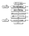
図4は、本実施形態に係る、改良された感度マップ及び改良されたマスクを用いてメインスキャンを処理する方法のフローチャートである。図示した実施形態では、パラレルイメージングサブルーチンBにはステップS410~426が含まれる。しかし、実施形態によっては、ステップS410~426の1つ又は複数は実行されなくてもよいし、又は図示した以外の順序で実行されてもよい。一実施形態によると、ステップS410~426は、上述のステップS308の処理の中で実行される。
MRIシステムは、パラレルイメージングサブルーチンBを開始する(ステップS400)。MRIシステムコントローラ22は、被検体の境界線(周縁部等)よりわずかに内側の位置を特定する(ステップS410)。上述のステップS304の処理で生成されたコイル感度マップ等のコイル感度マップが処理されて、スキャン対象の被検体の境界線(例えば、周縁部)が決定される。本明細書では、入力コイル感度マップ402を、これらのマップがまだ延長されていないことを反映して、「生のコイル感度マップ」と呼ぶ。しかし、実施形態によっては、それに対していくつかの更なる処理が既に実行されている可能性のあるコイル感度マップを用いてもよい。
ステップS410の処理では、例えば、被検体の2D表示(例えば、横断スライス画像)を用いた従来の境界線発見技術を用いて、スキャン対象の被検体の境界線を検出してもよい。境界線が特定されると、境界線のわずかに内側の位置にある一連の点が決定される。選択された一連の点から境界線までの厳密な距離は、設定可能である。例えば、選択された点は、境界線の内側の設定可能な数の画素であってもよいし、境界線から内側の設定可能な距離の測定値(例えば、ミリメートルやセンチメートル)であってもよいし、又は設定可能な距離範囲(例えば、0.5~1.5cm)内にあってもよい。別の実施形態によると、選択された一連の点の全てが、境界線から同じ距離にあるわけではない。例えば、境界線から異なる距離に位置する点があってもよく、これは最初に示された選択点が実際のコイル感度を十分正確に示す値を有していない場合があると判断されるからである。例えば、(設定された距離範囲により)最初に示された点の位置が骨や空洞域に非常に近い場合、最初に示された位置を、設定された距離範囲内にあるままで、間近の周辺領域内で不正確な感度値の原因となりうる骨や空洞域から離れるように、変更してもよい。
MRIシステムコントローラ22は、特定された位置の各点を位相エンコーディング方向に複製する(ステップS412)。すなわち、MRIシステムコントローラ22は、補正部として、本スキャンの実行により磁気共鳴画像に含まれる歪みに基づいて、感度分布を補正する。例えば、コイル感度マップ内の被検体の境界線が延長される。特に、ステップS410によって特定された一連の点からそれぞれの点が、少なくともメインスキャンの位相エンコーディング方向に、境界線から離れた設定可能な距離まで複製される。ここで、位相エンコーディング方向に複製されるのは、例えば、最も誤差が予想されるからであり、このように複製されるのは曲線当てはめによる外挿とは対照的である。一実施形態によると、位相エンコーディング方向に沿ったいずれかの方向の、画像再構成領域(field of view:FOV)の端まで、点を複製してもよい。例えば、位相エンコーディング方向が左右方向の場合、境界線が左右に延長されるように、境界線のわずかに内側から選択された点が複製される。
なお、換言すると、MRIシステムコントローラ22は、補正部として、磁気共鳴画像に含まれる歪みの方向に基づいて感度分布を拡張又は縮小する方向を求め、感度分布を補正する。具体的には、MRIシステムコントローラ22は、感度分布を複製により拡張又は縮小することで、感度分布を補正する。より具体的には、MRIシステムコントローラ22は、複製として、感度分布において被検体に対応する境界線の内側の点を位相エンコーディングの方向に複製する。また、歪みは、k空間において位相エンコーディング方向に沿って生じる歪みが磁気共鳴画像に現れた歪みである。
例示的な複製の例を図5A~5Cに示す。図5A~5Cは、本実施形態に係る、感度マップの延長を示す概略図を示したものである。生の、すなわち補正前の感度マップ502、例えば、各コイルにより取得されたような感度マップには、MRIシステムのメモリ又は記憶装置内でアクセスされる。生の感度マップ502はそれぞれ解析されて、外側の境界線504が特定される。図5Aに、特定された境界線504を有する生の感度マップ502を示す。次に、ステップS410について上述したように、位置506の一連の点が、図5Bに示すように境界線のわずかに内側で特定される。例えば、特定された境界線に比較的近い周縁部が特定される。一実施形態によると、頭部のスキャンでは、境界線の内側1cmの一連の点が特定される。次に、図5Cに示すように、ステップS412について上述したように、特定された位置506の一連の点から少なくともいくつかの点508及び510が、位置ずれが起こりそうな延長方向512及び514に延長される。この実施形態に示すように、位置ずれが起こりそうな方向は、メインスキャンに関連する位相エンコードの方向である。なお、この延長方向は、必ずしもプリスキャンの感度マップの位相エンコーディング方向に一致しなくても良い。延長方向512及び514における各点は、点508及び510を複製することにより実現される。上述のように、この実施形態における複製による点の延長は、一般に各コイルの空間多項式曲線の当てはめにより外挿することにより感度マップを延長してきた従来技術とは対照的である。さらに、この実施形態における点508及び510の位相エンコーディング方向への好ましい延長は、各コイルの多項式曲線の当てはめに従って様々な(例えば、おそらく全ての)方向に境界線を延長する従来技術とも対照的である。
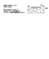
図6Aは、感度マップを延長する従来技術の例を示したものである。図6Bは、従来の方法により感度マップを延長することによって生じ得る誤差の例を示したものである。図7は、本実施形態に係る、感度マップを延長する技術を示したものである。図6Aに、スキャンした被検体の境界線を外挿によって延長する従来技術を示す。図6Bに、感度マップを延長するそのような従来技術によって生じ得る誤差の例を示す。図7に、例示的な実施形態に係る複製による感度マップの延長を示す。図6A~B及び図7において、物理的な位相エンコーディング方向が水平(左右)方向に沿っていることを前提とする。これらの小さい概要図における垂直方向は、信号強度軸として考えることができる。
図6Aに、従来技術に係るコイル感度値の延長を示す。スキャン対象の被検体の境界線602が決定される。一般に、検出された境界線内の領域は、信頼できる測定コイル感度値を有すると考えられる。このため、検出された境界線の内側の点の値に基づき、アレイの各コイル感度に対して、曲線当てはめの多項式が決定される。2つのコイルのアレイの例を考えてみると、アレイのコイル1及びコイル2それぞれのコイル感度を示す多項式604及び606が、検出された境界線602によって囲まれる領域内で対応する点の値に適合するように決定される。例えば、多項式604及び606を、周知の多項式適合技術のいずれかによって決定してもよい。スキャン対象の被検体の内部のための各コイル用の多項式602が決定されると、従来技術では、多項式604及び606のそれぞれを、検出された境界線の外側の領域610及び612に外挿する。例えば、Kingらの特許文献2及びBallesterらの特許文献3に記載されている外挿技術がある。なお、位置ずれや歪みのない真のコイル感度パターンが、被検体の外側で急上昇する可能性があることは一般的であるが、これはコイルアレイ導体が被検体の近くに位置する場合が一般的であり、信号位置とコイル導体素子との距離が短いために、ビオ-サバールの法則により高い感度が得られるからである。
図6Bに、従来の延長技術を適用した場合に、EPIにおいて生成されたような空間的位置ずれを起こした信号が、いかにして重大な誤差を生じさせ得るかを示す。被検体の検出された境界線620内にあるコイルの感度値632及び634(及び同じ感度によって強調された画像に関連付けられたEPI信号レベル)は、真の、すなわち正しい信号位置において示されると見なしうる。コイル感度(又は感度強調されたメイン画像(EPI)画素信号値)を示すものの位置ずれを起こした信号の位置にある値626及び628が、それぞれの正しい感度値632及び634の近くに現れることがある。実際のコイル感度が、対応する多項式の外挿に基づいて延長されると、比較的大きな誤差が発生することがある。例えば、位置ずれを起こした信号628とスキャンされた被検体の境界線620の内側の対応する真の信号634との間の位置ずれに起因する誤差の大きさは、展開位置638と対応する位置ずれ位置634との間の差を示す640によって示されているように、画像を再構成する際に相当大きなものとなる。
さらに、図6Bによると、コイル感度値634及び632を用いて対応する信号がエンコードされる。しかし、再構成展開の間に用いられる対応するコイル感度は、それぞれコイル感度値638及び636である。被検体の検出された境界線620の外側のこれらのコイル感度値は、各コイルのコイル感度値に適合する多項式に基づき決定される。図示したように、再構成の間に用いられるコイル感度である638と実際に信号をエンコードするコイル感度634との間の誤差640は、信号の特定の位置ずれに起因し、対応する実際の誤差よりも相当大きいものとなって現れる。634と638との間に生じる比較的大きい誤差の理由のひとつとして、各コイルのコイル感度に対応する曲線当てはめによる多項式に従って、検出された境界線の内側から外側へデータを外挿していることが挙げられる。
図7に、一実施形態に係る、検出された境界線の内側から延長された領域へ対応する値を複製することによる、検出された境界線650の内側から外側への点(例えば、コイル感度値)の延長(複製)を図示する。この結果、コイル1の感度マップは、検出された境界線の内側の領域における感度654と、延長された領域における感度658及び662とを含む。同様に、コイル2の感度マップは、検出された境界線の内側の領域における感度652と、延長された領域における感度656及び664とを含む。
ここで、図4の説明に戻る。MRIシステムコントローラ22は、感度エンコーディングマトリクス(単に、感度マトリクスとも称される)を生成する(ステップS414)。例えば、複製により延長された感度マップを用いて感度エンコーディングマトリクスが形成される。非特許文献1や特許文献2に開示されているような技術を用いて、感度エンコーディングマトリクスを決定することができる。感度エンコーディングマトリクスは、例えば、N×Cのマトリクスとすることができ、ここで各行iは、i=1…Nでフェーズドアレイコイルのコイルiを示し、また各列jは、j=1…Cで折り返し画素位置を示す。したがって、位置(i,j)におけるマトリクスの値は、コイルiにおいて受信されたときのj番目の画素に対する感度を示す。感度マトリクスの各要素の値は、プリスキャンの間に取得した感度マップから決定することができる。このため、上記のステップS412のように、感度マップを延長する前では、感度マップは、測定された感度値を含む。複製による延長の後では、感度マトリクスは、延長に基づく値を含んでもよい。
MRIシステムコントローラ22は、感度エンコーディングマトリクスを反転させて、デコーディングマトリクスを生成する(ステップS416)。デコーディングマトリクスにより、データを、感度マトリクス内で指定された複数のコイルから、複数の折り返されていない画素に変換して戻すことができる。反転は、ムーア-ペンローズの擬似逆行列等の周知のマトリクス反転技術によるものでもよい。これは、例えば、単純形式の均一な未補正雑音を前提とした、最小の雑音条件で、最小二乗法の閉形式解である。必要に応じて、非特許文献1に記載されているように、感度マトリクスの逆行列を決定する際に、受信機雑音レベル及び受信機チャネル内の雑音の補正を用いることができる。本明細書の例示的実施形態では、反転において、受信機雑音のレベル及び補正を考慮してもよいし、考慮しなくてもよい。しかし、受信機雑音レベルを考慮せずにデコーディングマトリクスを決定すると、信号対雑音比(signal-to-noise ratio:SNR)が低い点でいくらか不利になることが予想される。
MRIシステムコントローラ22は、メインスキャンデータ404を展開する(ステップS418)。メインスキャンデータの展開は、ステップS416で生成されたデコーディングマトリクスを用いて実行される。実施形態によっては、ステップS418における展開は、マスクを用いずに実行される。マスクにより、画像内のどのデータ点が、関心領域(region of interest:ROI)の外側にあるために無視することができるかが示される。別の実施形態によると、ステップS418における展開は、コイル感度マップ又はコイル感度マトリクスに基づき形成されたマスクの使用を含む。例えば、コイル感度マップ又はコイル感度マトリクスに基づき形成されたマスクにより、どの画素位置が関心領域の内側にあるのか、及びどの画素位置が外側にあるのかが示され、そのような情報を用いて、単にROIの内側及び/又は近くにある画素位置を考慮することにより、展開処理の質を改善することができる。なお、感度マトリクス及びその擬似逆行列であるデコーディングマトリクスは単一ではないため、反転により、通常メイン画像内に既に存在する(「g値」により定量化されているような)いかなる騒音も増幅されうる。g値を低減する(例えば、騒音を低減する)ための従来技術として、所定位置に信号がないはずであるということが感度マップから分かれば、エンコーディング及び反転から折り返し点を排除することがある。非特許文献1には、信号がない折り返し点を取り除くことにより感度マップのサイズを縮小すること、また、制約のある、より小さいシステムに対処できれば雑音を最小限にする自由度が増やせることが記載されている。エンコーディングマトリクスの全列を完全に取り除くことの他に、信号がほとんどない、あるいは全くない画素に対応する列を非強調することも妥当と思われる。Kingらの特許文献4に、感度マトリクスを改良し、マトリクス反転処理に正則化項を加えることにより、信号忠実度の多少の損失はあるものの雑音を低減する技術が記載されており、その内容は参照することによってその全体が本明細書に組み込まれる。従来、排除又は非強調する点は、本来折り返しがないため、プリスキャン感度マップを用いて識別される。
デコーディングマトリクスを用いてメインスキャンデータ(画像)を展開する技術は周知であり、非特許文献1に記載されているような技術を用いて、上記のようにデコーディングマトリクスを用いてメインスキャンデータから展開された診断画像を取得することができる。この段階で展開された診断画像を、中間的な診断画像と呼ぶ。
MRIシステムコントローラ22は、ステップS418で展開されたメインスキャンデータ(中間的な診断画像)からマスクを生成する(ステップS420)。マスクは、特定の画素又は領域が所要の画素輝度よりも低い画素輝度を有していると識別する閾値関数に基づき、決定することができる。所要の画素輝度は、設定可能であってもよい。マスクは、どの画像のデータ点がROIの外側にあるため無視することができるかを示すためのものである。マスクにより、スキャンされた被検体における対応する位置が、例えば被検体又はROIの外側にあるため信号に寄与していないとき、再構成における考慮から画素を除外することができる。一般に、再構成に寄与しそうにない画素を取り除くことにより、折り返しの程度が低減され、その結果とSNRが向上しうる。エンコーディングマトリクスからの画素の除外は、列が消去されたマトリクスを用いて、全体として行うことができ、あるいは、小さい値を乗じて列を非強調することにより、部分的にマトリクスのサイズを変えることなく、画素を除外することができる。列が非強調されて明確には除外されていない場合、全ての一連の折り返し画素に対して同じサイズのマトリクス反転を行うことができ、アルゴリズムを計算によるパラレル処理に適用してもよい。換言すると、ステップS418及びS420の処理により、MRIシステムコントローラ22は、マスク生成部として、パラレルイメージングで得られた信号に対して第1のアンフォールディング処理を施すことで、中間磁気共鳴画像を生成し、生成した中間磁気共鳴画像を用いて、マスク又は重み付け情報を生成する。
MRIシステムコントローラ22は、ステップS420で生成されたマスクを用いて、改良された感度エンコーディングマトリクスを生成する(ステップS422)。一実施形態によると、上述のように、感度マトリクス内の列は折り返しピクセルの位置を示す。一実施形態によると、マスクに基づいて、信号に寄与しない、あるいはROIの外側にある画素位置に対応する感度マトリクス内の1つ以上の列を取り除くことができる。
MRIシステムコントローラ22は、改良された感度マップを反転させて、改良されたデコーディングマトリクスを生成する(ステップS424)。このステップS424の処理は、ステップS416と同じ方法で実行してもよいが、改良された感度マトリクスに基づいて行う。デコーディングマトリクスを生成するために、改良された感度マトリクスを、受信機雑音を考慮して、あるいは考慮せずに、反転させることができる。
MRIシステムコントローラ22は、改良されたデコーディングマトリクスを用いて、メインスキャンデータ404を展開する(ステップS426)。このステップS426の処理は、改良されたデコーディングマトリクスに基づいて、ステップS418と同じ方法で実行してもよい。ステップS426の処理により、メインスキャンの出力画像が再構築される。換言すると、ステップS422~S426の処理により、MRIシステムコントローラ22は、生成部として、プリスキャンで得られた各コイルの感度分布と、パラレルイメージングで得られた信号と、マスク又は重み付け情報とを用いて、第2のアンフォールディング処理を施すことで、出力磁気共鳴画像を生成する。
このように、MRIシステムコントローラ22は、生成部として、補正後の感度分布を用いて、出力磁気共鳴画像を生成する。
図8は、本実施形態に係る、改良された感度マップを用いてメインスキャンを処理する方法のフローチャートである。図8には、本実施形態に係る、改良された感度マップを用いてメインスキャンデータを処理するフローチャートを示す。図示した実施形態では、パラレルイメージングサブルーチンCにはステップS806~814が含まれる。しかし、実施形態によっては、ステップS806~814の1つ又は複数は実行されなくてもよいし、図示した以外の順序で実行されてもよい。一実施形態によると、ステップS806~814は、上記のステップS308の処理の中で実行される。
なお、パラレルイメージングサブルーチンCにおいては、本明細書で開示する改良された感度マップを用いて診断画像を生成してもよいが、本明細書で開示する改良されたマスクの使用は必要としない。
MRIシステムは、パラレルイメージングサブルーチンCを開始する(ステップS800)。折り返されていない生の感度マップ802が、ステップS806への入力として提供される。生の感度マップ802は、受信用コイルから取得した感度マップであってもよい。ステップS806~S812の処理は、上述の対応するステップS410~S416の処理と同様に実行されてもよい。必要に応じて、ステップS810の処理において、ステップS414に関して述べた処理に加え、感度エンコーディングマトリクスを生成する際に、感度マップ又は感度マトリクスに基づいて生成されたマスクを考慮してもよい。デコーディングマトリクスを作成する際のマスクの使用については、他の操作に関連して上述している。
MRIシステムコントローラ22は、ステップS812の処理で生成されたデコーディングマトリクスを用いて、メインスキャンデータ804を展開する(ステップS814)。上述したように、メインスキャンデータ804は折り返し画像であってもよい。
図9は、本実施形態に係る、改良されたマスクを用いてメインスキャンデータを処理する方法のフローチャートである。図9に、本実施形態に係る、改良されたマスクを用いてメインスキャンデータを処理するパラレルイメージングサブルーチンDのフローチャートを示す。図示した実施形態では、パラレルイメージングサブルーチンDにはステップS906~918が含まれる。しかし、実施形態によっては、ステップS906~918の1つ又は複数は実行されなくてもよいし、図示した以外の順序で実行されてもよい。一実施形態によると、ステップS906~918は、上述のステップS308の処理の中で実行される。
なお、パラレルイメージングサブルーチンDにおいては、本明細書で開示する改良したマスクを用いて診断画像を生成してもよいが、本明細書で開示する改良された感度マップの使用は必要としない。
MRIシステムは、パラレルイメージングサブルーチンDを開始する(ステップS900)。折り返されていない生の感度マップ902が、ステップS906への入力として提供される。生の感度マップ902は、受信用コイルから取得した感度マップであってもよい。感度マトリクスが、感度マップに基づき生成される。実施形態によっては、感度マップをそれ以上処理することなく用いて、被検体の境界線を越えてマップを延長する。実施形態によっては、被検体の境界線を越えるように、マップをステップS906において延長してもよい。延長は、既知の(例えば、測定された)感度値の外挿に基づいてもよい。例えば、外挿は、図6Aに関して上述したような先行技術に従ってもよいが、図7に関して上述したような複製による延長技術を用いることが好ましい。
MRIシステムコントローラ22は、感度マップを用いて生成された感度マトリクスを反転させて、デコーディングマトリクスを作成する(ステップS908)。ここで、感度マップは、延長されていても延長されていなくてもよい。感度マトリクス及びデコーディングマトリクスの生成については、上述した。
MRIシステムコントローラ22は、デコーディングマトリクスを用いて、メインスキャンデータ904を展開する(ステップS910)。MRIシステムコントローラ22は、ステップS910の処理で展開されたメインスキャンデータに基づきマスクを生成する(ステップS912)。展開及びマスクの生成については、図4にて上述した。
MRIシステムコントローラ22は、ステップS912で生成されたマスクを用いて、改良された感度エンコーディングマトリクスを生成し(ステップS914)、感度マトリクスが処理される。ステップS422に関して上述したのと同様の方法で、信号を提供しないか関心領域の外側にあるかのいずれかの画素位置を取り除くか源弱することにより、改良された感度マトリクスを生成してもよい。
MRIシステムコントローラ22は、ステップS914の処理により生成された、改良された感度エンコーディングマトリクスを反転させて、改良されたデコーディングマトリクスを生成する(ステップS916)。MRIシステムコントローラ22は、ステップS916の処理からの改良されたデコーディングマトリクスを用いて、メインスキャンデータ904を展開する(ステップS918)。
図10は、EPIにおいて2D位相補正を組み合わせて、本実施形態による改良された感度マップ及び改良されたマスクを使用する方法のフローチャートである。図10に、EPIにおける2D位相補正と組み合わせて、本実施形態に係る、改良されたマスクと組み合わせて改良された感度マップを用いるフローチャートを示す。図示した実施形態では、パラレルイメージングサブルーチンEにはステップS1022~S1050が含まれる。しかし、実施形態によっては、ステップS1022~S1050の1つ又は複数は実行されなくてもよいし、図示した以外の順序で実行されてもよい。一実施形態によると、ステップS1022~S1050は、上記のステップS308の処理の中で実行される。
パラレルイメージングサブルーチンEでは、EPIにおける2D位相補正を使用して、本明細書に開示するような、改良された感度マップと改良されたマスクとを組み合わせている。2D位相補正は、EPI画像内のナイキストゴーストが取り除くために頻繁に用いられる。非特許文献2には、EPIにおける2D位相補正が記載されている。概して、方法ステップS1000に、2Dナイキスト低空間周波数ゴーストの補正と共に、本明細書に開示されるような改良された感度マップ及び改良されたマスクの使用を示す。
MRIシステムは、パラレルイメージングサブルーチンEを開始する(ステップS1000)。MRIシステムコントローラ22は、コイル感度マップ1002を位相エンコーディング方向に延長する(ステップS1022)。ステップS410~S412に関して上述したように、コイル感度マップ1002の延長は、被検体の境界線のわずかに内側にある感度マップ又はプリスキャン画像上の領域の位置を特定する工程と、位相エンコーディング方向に識別された画素を複製により延長する工程とを含んでもよい。延長された感度マップ1008を、メモリに保持してもよい。
MRIシステムコントローラ22は、EPIナイキストプリスキャンデータ1004が入力として取り込まれ、2Dフーリエ変換(2D Fourier transform:2DFT)を用いて偶数と奇数とで別々の基準画像を生成する(ステップS1024)。このEPIナイキストプリスキャンデータ1004は、「EPIテンプレート」としても知られている。EPIテンプレートは、感度マップを取得するプリスキャンとは別のプリスキャンにおいて取得したものであってもよい。MRIシステムコントローラ22は、奇数及び偶数の基準画像を用いて、偶数行画像と奇数行画像の位相差を決定する(ステップS1026)。MRIシステムコントローラ22は、複数チャネルにわたる位相差が追加処理有り又は無しで蓄積され、複数のチャネルの信号を足し合わせ、その実部及び虚部の信号値からarctangentで位相を求め(ATNA)(ステップS1028)、ナイキスト補正マップ1010が生成される。実施形態によっては、ナイキスト補正マップ1010により、ナイキストゴーストを取り除くために必要な乗法的複合位相マップが識別される。
MRIシステムコントローラ22は、EPIメインスキャン1006の画像の中から、基準MRIデータ取得ショットを選択する(ステップS1030)。MRIシステムコントローラ22は、選択された基準画像に基づき、マスク生成用の偶数及び奇数の2DFT画像データを決定する(ステップS1032)。
MRIシステムコントローラ22は、ステップS1032で決定された偶数及び奇数の2DFT画像データ、ナイキスト補正マップ1010、及び延長された感度マップ1008が入力として取り込まれ、中間EPI画像1036を生成する(ステップS1034)。なお、このステップS1034の処理は、感度マトリクスをエンコードする工程と、感度マトリクスを反転させてデコーディングマトリクスを生成する工程と、次にデコーディングマトリクスを用いてEPI画像を展開する工程とを含んでもよい。しかし、EPI画像1036は、高いg値を有し得るという意味で準最適である。
MRIシステムコントローラ22は、準最適なEPI画像1036に基づき、輝度値が閾値未満の画素の位置を識別する(閾値処理)(ステップS1038)。閾値は、設定されたものでよいし、動的に決定されたものでもよい。これらの位置を、それぞれの位置がスキャンされた被検体から広がるにつれて、それぞれの位置の強調が小さくなるようにした非強調マップとしてもよい。この結果、閾値未満であると識別された画素位置を用いて、マスク又は非強調マップ1012が決定される。なお、この非強調マップは、画素の位置に応じて輝度値の重みが付けられた重み付け情報の一例である。
MRIシステムコントローラ22は、偶数及び奇数の2DFTが、全てのEPIメインスキャン画像1006に対して決定する(ステップS1040)。次に、MRIシステムコントローラ22は、EPIメインスキャン画像1006のそれぞれから得られた偶数及び奇数の2DFT画像データを、マスク1012、ナイキスト補正マップ1010、及び延長された感度マップ1008とまとめて考慮して、g値が所望の値まで低減された最終的なEPI画像1050を生成する(ステップS1042)。なお、ステップS1042の処理は、ステップS1034の処理と同様に、感度マトリクスをエンコードする工程と、デコーディングマトリクスを生成する工程と、デコーディングマトリクスを用いてEPI画像を展開する工程とを含む。
次に、最終EPI画像を、部分k空間ホモダインフィルタリング補正(Partial K-Space Homodyne Filtering Correction:PKH)、高周波画像均一化補正(radio frequency Image Uniformity Correction:IUC)、傾斜歪み補正(Gradient Distortion Correction:GDC)等の、様々な後処理機能にかけることができる。最終EPI画像又は後処理後の最終EPI画像から、最終診断画像(出力画像)が得られる。
当然のことながら、上記の実施形態は、
(a)最終的な展開された診断画像を得るために生の画像データをさらに処理する際に使用するより正確なマスクを生成するための、展開された「中間的な」診断画像と、
(b)診断画像を最終的に展開する際に用いる、(曲線当てはめによる外挿ではなく)複製によるコイル感度マップの延長と
のいずれか又は両方を用いることにより、改良されたパラレルMRイメージングを提供する。
(a)最終的な展開された診断画像を得るために生の画像データをさらに処理する際に使用するより正確なマスクを生成するための、展開された「中間的な」診断画像と、
(b)診断画像を最終的に展開する際に用いる、(曲線当てはめによる外挿ではなく)複製によるコイル感度マップの延長と
のいずれか又は両方を用いることにより、改良されたパラレルMRイメージングを提供する。
(パラレルイメージング以外への適用)
なお、上記の説明では、MRIシステムがパラレルイメージングによる撮像を行う場合を説明したが、実施形態はこれに限定されるものではない。例えば、上記の改善された感度マップ(感度分布)は、輝度補正に用いることもできる。
なお、上記の説明では、MRIシステムがパラレルイメージングによる撮像を行う場合を説明したが、実施形態はこれに限定されるものではない。例えば、上記の改善された感度マップ(感度分布)は、輝度補正に用いることもできる。
具体的には、従来、出力磁気共鳴画像(出力画像)を得るために、プリスキャン(例えば、リファレンススキャン)で得られた感度分布を用いて輝度補正を行うことが行われている。しかしながら、例えばEPIによって本スキャンを行うと、図2Aに示したように、得られた画像が歪んでしまうため、プリスキャンで得られた感度分布を用いても適切な輝度補正を行うことができず、出力画像の画質が低下してしまう場合があった。
そこで、本実施形態に係るMRIシステムは、EPIによって得られた画像に対して、本実施形態に係る感度分布(例えば図7)を用いて輝度補正を行う。これにより、MRIシステムは、歪んだ画像に対して延長された感度分布を用いて輝度補正を行うこととなるので、適切に輝度補正を行うことができ、出力画像の画質を向上させることができる。
(EPI以外への適用)
また、上記の説明では、MRIシステムがEPIを用いた撮像を行う場合を説明したが、実施形態はこれに限定されるものではない。例えば、上記の問題は、EPIに限らず、傾斜磁場の極性が反転するようなパルスシーケンスが行われる場合にも生じうる。このため、実施形態に係るMRIシステムは、EPIに限らず、傾斜磁場の極性が反転するようなパルスシーケンスが行われる場合に適用されても良い。
また、上記の説明では、MRIシステムがEPIを用いた撮像を行う場合を説明したが、実施形態はこれに限定されるものではない。例えば、上記の問題は、EPIに限らず、傾斜磁場の極性が反転するようなパルスシーケンスが行われる場合にも生じうる。このため、実施形態に係るMRIシステムは、EPIに限らず、傾斜磁場の極性が反転するようなパルスシーケンスが行われる場合に適用されても良い。
また、当業者には明らかなように、代わりに「正則化」処理を用いる場合は、マスクを生成又は使用しないことも可能である。
以上説明した少なくともひとつの実施形態によれば、出力画像の画質を向上させることができる。
本発明のいくつかの実施形態を説明したが、これらの実施形態は、例として提示したものであり、発明の範囲を限定することは意図していない。これら実施形態は、その他の様々な形態で実施されることが可能であり、発明の要旨を逸脱しない範囲で、種々の省略、置き換え、変更を行うことができる。これら実施形態やその変形は、発明の範囲や要旨に含まれると同様に、請求の範囲に記載された発明とその均等の範囲に含まれるものである。
Claims (8)
- コイルの感度分布を収集するプリスキャンを実行するプリスキャン部と、
磁気共鳴画像の信号を収集する本スキャンを実行する本スキャン部と、
前記本スキャンの実行により磁気共鳴画像に含まれる歪みに基づいて、前記感度分布を補正する補正部と、
前記補正後の感度分布を用いて、出力磁気共鳴画像を生成する生成部と
を備える、磁気共鳴イメージング装置。 - 前記歪みは、k空間において位相エンコーディング方向に沿って生じる歪みが前記磁気共鳴画像に現れた歪みである、請求項1に記載の磁気共鳴イメージング装置。
- 前記補正部は、前記磁気共鳴画像に含まれる歪みの方向に基づいて前記感度分布を拡張又は縮小する方向を求め、前記感度分布を補正する、請求項1に記載の磁気共鳴イメージング装置。
- 前記補正部は、前記感度分布を複製により拡張又は縮小することで、当該感度分布を補正する、請求項1に記載の磁気共鳴イメージング装置。
- 前記補正部は、前記複製として、前記感度分布において被検体に対応する境界線の内側の点を位相エンコーディング方向に複製する、請求項4に記載の磁気共鳴イメージング装置。
- 前記プリスキャン部は、前記プリスキャンとして、複数のコイルのそれぞれの感度分布を収集し、
前記本スキャン部は、前記本スキャンとして、パラレルイメージングを実行し、
前記生成部は、前記パラレルイメージングで得られた前記信号に対して第1のアンフォールディング処理を施すことで、中間磁気共鳴画像を生成し、生成した中間磁気共鳴画像を用いて、マスク又は重み付け情報を生成し、前記プリスキャンで得られた各コイルの感度分布と、前記パラレルイメージングで得られた前記信号と、前記マスク又は前記重み付け情報とを用いて、第2のアンフォールディング処理を施すことで、前記出力磁気共鳴画像を生成する、請求項1~5のいずれか一つに記載の磁気共鳴イメージング装置。 - 前記本スキャン部は、前記本スキャンとして、EPI(Echo Planar Imaging)を実行する、請求項1に記載の磁気共鳴イメージング装置。
- 複数のコイルのそれぞれの感度分布を収集するプリスキャンを実行するプリスキャン部と、
磁気共鳴画像の信号を収集する本スキャンとして、パラレルイメージングを実行する本スキャン部と、
前記パラレルイメージングで得られた前記信号に対して第1のアンフォールディング処理を施すことで、中間磁気共鳴画像を生成し、生成した中間磁気共鳴画像を用いて、マスク又は重み付け情報を生成するマスク生成部と、
前記プリスキャンで得られた各コイルの感度分布と、前記パラレルイメージングで得られた前記信号と、前記マスク又は前記重み付け情報とを用いて、第2のアンフォールディング処理を施すことで、出力磁気共鳴画像を生成する生成部と
を備える、磁気共鳴イメージング装置。
Priority Applications (2)
| Application Number | Priority Date | Filing Date | Title |
|---|---|---|---|
| CN201480001863.9A CN104486993B (zh) | 2013-06-10 | 2014-06-10 | 磁共振成像装置 |
| US14/963,973 US10365344B2 (en) | 2013-06-10 | 2015-12-09 | Magnetic resonance imaging apparatus |
Applications Claiming Priority (2)
| Application Number | Priority Date | Filing Date | Title |
|---|---|---|---|
| US13/914,160 US10534060B2 (en) | 2013-06-10 | 2013-06-10 | Parallel MRI with spatially misregistered signal |
| US13/914,160 | 2013-06-10 |
Related Parent Applications (1)
| Application Number | Title | Priority Date | Filing Date |
|---|---|---|---|
| US13/914,160 Continuation-In-Part US10534060B2 (en) | 2013-06-10 | 2013-06-10 | Parallel MRI with spatially misregistered signal |
Related Child Applications (1)
| Application Number | Title | Priority Date | Filing Date |
|---|---|---|---|
| US14/963,973 Continuation US10365344B2 (en) | 2013-06-10 | 2015-12-09 | Magnetic resonance imaging apparatus |
Publications (1)
| Publication Number | Publication Date |
|---|---|
| WO2014199997A1 true WO2014199997A1 (ja) | 2014-12-18 |
Family
ID=52004947
Family Applications (1)
| Application Number | Title | Priority Date | Filing Date |
|---|---|---|---|
| PCT/JP2014/065385 Ceased WO2014199997A1 (ja) | 2013-06-10 | 2014-06-10 | 磁気共鳴イメージング装置 |
Country Status (4)
| Country | Link |
|---|---|
| US (2) | US10534060B2 (ja) |
| JP (1) | JP6523619B2 (ja) |
| CN (1) | CN104486993B (ja) |
| WO (1) | WO2014199997A1 (ja) |
Families Citing this family (27)
| Publication number | Priority date | Publication date | Assignee | Title |
|---|---|---|---|---|
| US10534060B2 (en) | 2013-06-10 | 2020-01-14 | Toshiba Medical Systems Corporation | Parallel MRI with spatially misregistered signal |
| US9606210B2 (en) * | 2013-09-04 | 2017-03-28 | Toshiba Medical Systems Corporation | Magnetic resonance imaging apparatus and magnetic resonance imaging method |
| WO2016071054A1 (en) * | 2014-11-07 | 2016-05-12 | Koninklijke Philips N.V. | Method and system for generating mr images of a moving object in its environment |
| CN106137198B (zh) * | 2015-04-10 | 2021-04-30 | Ge医疗系统环球技术有限公司 | 一种磁共振成像方法及装置 |
| CN108431624B (zh) * | 2015-12-17 | 2021-05-25 | 皇家飞利浦有限公司 | 定量磁化率映射磁共振图像的分割 |
| JP6851387B2 (ja) | 2016-02-12 | 2021-03-31 | ヴィジランス ヘルス イメージング ネットワーク インコーポレイテッドVigilance Health Imaging Network Inc. | 全身参照画像に基づく複数のmri画像の歪み補正 |
| US10605883B2 (en) * | 2016-04-22 | 2020-03-31 | Sunnybrook Research Institute | System and method for producing distortion free magnetic resonance images using dual-echo echo-planar imaging |
| CN107689252B (zh) * | 2016-08-03 | 2021-07-30 | 西门子(深圳)磁共振有限公司 | 核磁共振扫描控制装置、方法和核磁共振扫描仪 |
| WO2018036986A1 (en) | 2016-08-25 | 2018-03-01 | Koninklijke Philips N.V. | Bo-corrected sensitivity encoding magnetic resonance imaging |
| JP2018093325A (ja) * | 2016-12-01 | 2018-06-14 | ソニーセミコンダクタソリューションズ株式会社 | 情報処理装置、情報処理方法、及びプログラム |
| US10359493B2 (en) * | 2016-12-30 | 2019-07-23 | General Electric Company | MRI system and method for performing time resolved MR imaging of an object with grouped data acquisition |
| US10459051B2 (en) * | 2017-01-05 | 2019-10-29 | Siemens Healthcare Gmbh | Field of view increase in magnetic resonance imaging using nonlinear gradients and generalized iterative reconstruction |
| US20190041481A1 (en) * | 2017-08-04 | 2019-02-07 | Muralidhara Subbarao | Massively parallel magnetic resonance imaging wherein numerous off-surface coils are used to acquire partially under-sampled magnetic resonance signal data |
| JP6820876B2 (ja) * | 2018-03-20 | 2021-01-27 | 株式会社日立製作所 | 磁気共鳴撮影装置、感度分布算出方法、及び、感度分布算出プログラム |
| US11004183B2 (en) * | 2018-07-10 | 2021-05-11 | The Board Of Trustees Of The Leland Stanford Junior University | Un-supervised convolutional neural network for distortion map estimation and correction in MRI |
| DE102018219457B3 (de) | 2018-11-14 | 2020-01-09 | Siemens Healthcare Gmbh | Verfahren zur MR-Bildrekonstruktion und MR-System |
| US11415656B2 (en) * | 2019-01-30 | 2022-08-16 | Canon Medical Systems Corporation | Medical information processing apparatus, magnetic resonance imaging apparatus, and medical information processing method |
| US12396654B2 (en) * | 2019-04-25 | 2025-08-26 | Children's Medical Center Corporation | Reconstruction augmentation by constraining with intensity gradients in MRI |
| CN110265120B (zh) * | 2019-05-09 | 2021-10-22 | 上海联影医疗科技股份有限公司 | 医学图像处理方法、装置、计算机设备和存储介质 |
| CN110703170B (zh) * | 2019-09-27 | 2021-08-31 | 河北惠仁医疗设备科技有限公司 | 一种乳腺专用mri梯度线圈的设计方法 |
| JP7455007B2 (ja) | 2020-06-22 | 2024-03-25 | キヤノンメディカルシステムズ株式会社 | 装置、システム、およびプログラム |
| JP7487047B2 (ja) | 2020-08-21 | 2024-05-20 | 富士フイルムヘルスケア株式会社 | 磁気共鳴イメージング装置、及び、その制御方法及びプログラム |
| US11828824B2 (en) * | 2021-03-17 | 2023-11-28 | GE Precision Healthcare LLC | System and method for deep learning-based accelerated magnetic resonance imaging with extended field of view coil sensitivity calibration |
| JP7608268B2 (ja) | 2021-05-20 | 2025-01-06 | 富士フイルム株式会社 | 磁気共鳴撮影装置及び感度分布算出プログラム |
| KR102604679B1 (ko) * | 2021-07-06 | 2023-11-23 | 한국과학기술원 | 자화준비 이미징을 위한 싱글-샷 의사-센트릭 epi 방법 |
| WO2024225663A1 (ko) * | 2023-04-24 | 2024-10-31 | 삼성전자 주식회사 | 이미지를 복원하기 위한 전자 장치 및 그 동작 방법 |
| CN121541121B (zh) * | 2026-01-21 | 2026-03-20 | 内蒙古医科大学附属医院(内蒙古自治区心血管研究所) | 头颈部柔性磁共振无线线圈多通道信号协同采集系统 |
Citations (6)
| Publication number | Priority date | Publication date | Assignee | Title |
|---|---|---|---|---|
| WO2002056767A1 (fr) * | 2001-01-19 | 2002-07-25 | Kabushiki Kaisha Toshiba | Imagerie parallele par resonance magnetique utilisant une carte de sensibilite de bobine haute precision |
| JP2002315731A (ja) * | 2001-04-20 | 2002-10-29 | Hitachi Medical Corp | 磁気共鳴イメージング装置 |
| JP2004275198A (ja) * | 2003-03-12 | 2004-10-07 | Ge Medical Systems Global Technology Co Llc | 核磁気共鳴イメージング装置、および核磁気共鳴イメージング方法 |
| JP2009142522A (ja) * | 2007-12-17 | 2009-07-02 | Hitachi Medical Corp | 磁気共鳴イメージング装置 |
| JP2009160408A (ja) * | 2007-12-29 | 2009-07-23 | Siemens Ag | 磁気共鳴イメージングにおける歪み補正方法及び装置 |
| JP2011200637A (ja) * | 2010-03-05 | 2011-10-13 | Toshiba Corp | 磁気共鳴イメージング装置 |
Family Cites Families (18)
| Publication number | Priority date | Publication date | Assignee | Title |
|---|---|---|---|---|
| JPH0759750A (ja) * | 1993-08-30 | 1995-03-07 | Hitachi Medical Corp | 核磁気共鳴イメージング装置 |
| US6876201B2 (en) | 2001-02-23 | 2005-04-05 | Hitachi Medical Corporation | Magnetic resonance imaging apparatus and method |
| US6559642B2 (en) | 2001-05-09 | 2003-05-06 | Ge Medical Systems Global Technology Company, Llc | Calibration method for use with sensitivity encoding MRI acquisition |
| US6486671B1 (en) | 2001-05-14 | 2002-11-26 | Ge Medical Systems Global Technologies Company Llc | MRI image quality improvement using matrix regularization |
| US6654976B2 (en) * | 2001-07-06 | 2003-12-02 | Rite-Hite Holding Corporation | Seal for a dock leveler lip |
| US7197353B2 (en) | 2001-09-14 | 2007-03-27 | General Electric Company | Sensitivity encoding MRI acquisition method |
| US6836116B2 (en) | 2002-07-01 | 2004-12-28 | Ge Medical Systems Global Technology Company, Llc. | Sensitivity encoding magnetic resonance imaging method and system |
| JP4676684B2 (ja) * | 2003-08-26 | 2011-04-27 | クラリオン株式会社 | 車載情報端末 |
| CN100479748C (zh) | 2004-03-26 | 2009-04-22 | 株式会社东芝 | 核磁共振成像装置 |
| JP2009505711A (ja) | 2005-08-23 | 2009-02-12 | コーニンクレッカ フィリップス エレクトロニクス エヌ ヴィ | 並行磁気共鳴撮像のための装置および方法 |
| US7485969B2 (en) * | 2005-09-01 | 2009-02-03 | Micron Technology, Inc. | Stacked microelectronic devices and methods for manufacturing microelectronic devices |
| US7218110B2 (en) | 2005-09-02 | 2007-05-15 | Toshiba America Mri, Inc. | Method and apparatus for diffusion magnetic resonance imaging with the effects of eddy currents compensated |
| US20090285463A1 (en) * | 2008-04-18 | 2009-11-19 | Ricardo Otazo | Superresolution parallel magnetic resonance imaging |
| JP5502682B2 (ja) | 2010-09-28 | 2014-05-28 | 株式会社東芝 | 磁気共鳴イメージング装置 |
| DE102011083898B4 (de) | 2011-09-30 | 2013-04-11 | Friedrich-Alexander-Universität Erlangen-Nürnberg | Erfassen von Magnetresonanzdaten am Rande des Gesichtsfelds einer Magnetresonanzanlage |
| JP6042069B2 (ja) | 2012-01-25 | 2016-12-14 | 東芝メディカルシステムズ株式会社 | 磁気共鳴イメージング装置 |
| US8918159B2 (en) * | 2012-04-18 | 2014-12-23 | Mayo Foundation For Medical Education And Research | System and method for improved accelerated magnetic resonance imaging using ROI masking |
| US10534060B2 (en) * | 2013-06-10 | 2020-01-14 | Toshiba Medical Systems Corporation | Parallel MRI with spatially misregistered signal |
-
2013
- 2013-06-10 US US13/914,160 patent/US10534060B2/en active Active
-
2014
- 2014-06-10 CN CN201480001863.9A patent/CN104486993B/zh active Active
- 2014-06-10 JP JP2014119987A patent/JP6523619B2/ja active Active
- 2014-06-10 WO PCT/JP2014/065385 patent/WO2014199997A1/ja not_active Ceased
-
2015
- 2015-12-09 US US14/963,973 patent/US10365344B2/en active Active
Patent Citations (6)
| Publication number | Priority date | Publication date | Assignee | Title |
|---|---|---|---|---|
| WO2002056767A1 (fr) * | 2001-01-19 | 2002-07-25 | Kabushiki Kaisha Toshiba | Imagerie parallele par resonance magnetique utilisant une carte de sensibilite de bobine haute precision |
| JP2002315731A (ja) * | 2001-04-20 | 2002-10-29 | Hitachi Medical Corp | 磁気共鳴イメージング装置 |
| JP2004275198A (ja) * | 2003-03-12 | 2004-10-07 | Ge Medical Systems Global Technology Co Llc | 核磁気共鳴イメージング装置、および核磁気共鳴イメージング方法 |
| JP2009142522A (ja) * | 2007-12-17 | 2009-07-02 | Hitachi Medical Corp | 磁気共鳴イメージング装置 |
| JP2009160408A (ja) * | 2007-12-29 | 2009-07-23 | Siemens Ag | 磁気共鳴イメージングにおける歪み補正方法及び装置 |
| JP2011200637A (ja) * | 2010-03-05 | 2011-10-13 | Toshiba Corp | 磁気共鳴イメージング装置 |
Also Published As
| Publication number | Publication date |
|---|---|
| JP6523619B2 (ja) | 2019-06-05 |
| US20160097831A1 (en) | 2016-04-07 |
| CN104486993B (zh) | 2017-07-14 |
| CN104486993A (zh) | 2015-04-01 |
| JP2014236987A (ja) | 2014-12-18 |
| US10534060B2 (en) | 2020-01-14 |
| US20140361770A1 (en) | 2014-12-11 |
| US10365344B2 (en) | 2019-07-30 |
Similar Documents
| Publication | Publication Date | Title |
|---|---|---|
| JP6523619B2 (ja) | 磁気共鳴イメージング装置 | |
| JP6430290B2 (ja) | 磁気共鳴イメージング装置 | |
| US8648599B2 (en) | Magnetic resonance imaging apparatus and magnetic resonance imaging method | |
| JP6333293B2 (ja) | 金属耐性mr画像化 | |
| CN105308469B (zh) | 一种mr成像方法、mr设备以及相关数据载体 | |
| US9476959B2 (en) | MRI ghosting correction using unequal magnitudes ratio | |
| US10089722B2 (en) | Apparatus and method for reducing artifacts in MRI images | |
| US9606210B2 (en) | Magnetic resonance imaging apparatus and magnetic resonance imaging method | |
| US20160170000A1 (en) | Method and apparatus for acquiring magnetic resonance data and entering the data into k-space | |
| JP5422194B2 (ja) | 磁気共鳴イメージング装置 | |
| US10884087B2 (en) | Apparatuses and methods to improve chemical species separation in magnetic resonance imaging | |
| JP2016022302A (ja) | 磁気共鳴信号処理方法、磁気共鳴信号処理装置及び磁気共鳴装置並びにプログラム | |
| JP7350568B2 (ja) | 磁気共鳴データ収集方法及び磁気共鳴イメージング装置 | |
| US10481235B2 (en) | Magnetic resonance imaging apparatus and image processing apparatus | |
| JP7399781B2 (ja) | 磁気共鳴イメージング装置及び磁気共鳴イメージング方法 | |
| JP6820876B2 (ja) | 磁気共鳴撮影装置、感度分布算出方法、及び、感度分布算出プログラム | |
| JP7183048B2 (ja) | 磁気共鳴イメージングシステム、磁気共鳴イメージング方法、及び磁気共鳴イメージングプログラム | |
| JP2019098144A (ja) | 磁気共鳴イメージング装置及び画像処理装置 | |
| JP2022178683A (ja) | 磁気共鳴撮影装置及び感度分布算出プロブラム | |
| US10317495B2 (en) | Method and computer use of an MR overview dataset for reconstruction of MR raw data | |
| JP7532210B2 (ja) | 画像処理装置、および画像処理方法 | |
| CN115486829B (zh) | 磁共振图像的相位校正系统和方法 | |
| JP2025037822A (ja) | B1マップ決定方法及びb1マップ決定装置 | |
| CN115113122A (zh) | 图像处理装置以及图像处理方法 |
Legal Events
| Date | Code | Title | Description |
|---|---|---|---|
| 121 | Ep: the epo has been informed by wipo that ep was designated in this application |
Ref document number: 14811260 Country of ref document: EP Kind code of ref document: A1 |
|
| NENP | Non-entry into the national phase |
Ref country code: DE |
|
| 122 | Ep: pct application non-entry in european phase |
Ref document number: 14811260 Country of ref document: EP Kind code of ref document: A1 |
|
| NENP | Non-entry into the national phase |
Ref country code: JP |