WO2014199758A1 - ドップラシフト周波数測定装置及びそれを備えた潮流計 - Google Patents
ドップラシフト周波数測定装置及びそれを備えた潮流計 Download PDFInfo
- Publication number
- WO2014199758A1 WO2014199758A1 PCT/JP2014/062663 JP2014062663W WO2014199758A1 WO 2014199758 A1 WO2014199758 A1 WO 2014199758A1 JP 2014062663 W JP2014062663 W JP 2014062663W WO 2014199758 A1 WO2014199758 A1 WO 2014199758A1
- Authority
- WO
- WIPO (PCT)
- Prior art keywords
- doppler shift
- shift frequency
- echo signal
- frequency
- signal component
- Prior art date
- Legal status (The legal status is an assumption and is not a legal conclusion. Google has not performed a legal analysis and makes no representation as to the accuracy of the status listed.)
- Ceased
Links
Images




Classifications
-
- G—PHYSICS
- G01—MEASURING; TESTING
- G01S—RADIO DIRECTION-FINDING; RADIO NAVIGATION; DETERMINING DISTANCE OR VELOCITY BY USE OF RADIO WAVES; LOCATING OR PRESENCE-DETECTING BY USE OF THE REFLECTION OR RERADIATION OF RADIO WAVES; ANALOGOUS ARRANGEMENTS USING OTHER WAVES
- G01S15/00—Systems using the reflection or reradiation of acoustic waves, e.g. sonar systems
- G01S15/02—Systems using the reflection or reradiation of acoustic waves, e.g. sonar systems using reflection of acoustic waves
- G01S15/50—Systems of measurement, based on relative movement of the target
- G01S15/58—Velocity or trajectory determination systems; Sense-of-movement determination systems
- G01S15/60—Velocity or trajectory determination systems; Sense-of-movement determination systems wherein the transmitter and receiver are mounted on the moving object, e.g. for determining ground speed, drift angle, ground track
-
- G—PHYSICS
- G01—MEASURING; TESTING
- G01P—MEASURING LINEAR OR ANGULAR SPEED, ACCELERATION, DECELERATION, OR SHOCK; INDICATING PRESENCE, ABSENCE, OR DIRECTION, OF MOVEMENT
- G01P5/00—Measuring speed of fluids, e.g. of air stream; Measuring speed of bodies relative to fluids, e.g. of ship, of aircraft
- G01P5/24—Measuring speed of fluids, e.g. of air stream; Measuring speed of bodies relative to fluids, e.g. of ship, of aircraft by measuring the direct influence of the streaming fluid on the properties of a detecting acoustical wave
- G01P5/241—Measuring speed of fluids, e.g. of air stream; Measuring speed of bodies relative to fluids, e.g. of ship, of aircraft by measuring the direct influence of the streaming fluid on the properties of a detecting acoustical wave by using reflection of acoustical waves, i.e. Doppler-effect
Definitions
- the present invention relates to, for example, a Doppler shift frequency measuring device that measures a Doppler shift frequency of an ultrasonic wave transmitted in water, and a tide meter provided with the Doppler shift frequency measuring device.
- tidal currents have been measured with a tide meter for the purpose of fishing assistance and marine research.
- the tide meter is attached to the bottom of a ship and includes a transducer that transmits and receives ultrasonic waves at a certain depression angle ⁇ with respect to directions that are 120 degrees apart from each other in the horizontal direction, for example.
- the tidal current meter allows the ship's velocity (relative to the tidal current) from the Doppler shift frequency generated in reflected waves (against water echoes) resulting from countless scatterers (plankton, etc.) in the sea located at the set depth. Calculate water speed).
- the tide meter determines the speed of the ship (ground speed) with respect to the sea floor from the Doppler shift frequency generated in the reflected wave (ground echo) from the sea floor. Furthermore, the tidal current meter determines the tidal current speed from the difference between the ground speed and the speed of water.
- the directivity characteristic of this type of tidal current meter has a main lobe in the direction of the depression angle ⁇ and has a side lobe that opens in an umbrella shape at a certain angle from the main lobe and goes in the vertical direction. .
- the received signal of the transmitter / receiver is obtained by adding the received signal component due to the side lobe to the received signal component due to the main lobe, particularly near the sea floor. There was a problem that the speed could not be measured.
- the angle between the direction of the main lobe and the vertical line is made smaller than the angle between the direction of the side lobe and the vertical line, thereby increasing the intensity of the bottom reflected wave from the side lobe.
- an underwater detection device that is lowered and can extract a reflected wave from the bottom of the main lobe (see Patent Document 1).
- the present invention has been made in view of the circumstances as described above, and provides a Doppler shift frequency measuring apparatus capable of measuring a Doppler shift frequency with higher accuracy than conventional ones and a tide meter including the Doppler shift frequency measurement apparatus. For the purpose.
- the Doppler shift frequency measuring device includes an ultrasonic wave having a main lobe heading in a direction of a predetermined depression angle and a side lobe that opens in an umbrella shape at a predetermined angle from the main lobe and whose main directing direction is a vertical direction.
- a transmitter / receiver for receiving the ultrasonic echo signal, and a signal component in a predetermined cutoff band with the ultrasonic frequency as a center frequency from the echo signal received by the transmitter / receiver.
- a Doppler shift frequency detecting means for detecting a Doppler shift frequency of the echo signal component due to the main lobe included in the echo signal from which the signal component of the cutoff band is removed. .
- the Doppler shift frequency measuring apparatus of the present invention can remove the echo signal component due to the side lobe by the filter means, so that the angle formed by the main lobe pointing direction and the vertical line is different from the conventional one.
- the Doppler shift frequency of the echo signal component due to the main lobe can be detected without reducing it. Therefore, the Doppler shift frequency measuring apparatus of the present invention can measure the Doppler shift frequency with higher accuracy than the conventional one.
- the Doppler shift frequency measuring device of the present invention has a configuration in which the filter means removes an echo signal component generated by reflection of the ultrasonic waves of the side lobes at the bottom of the water.
- the Doppler shift frequency measuring device of the present invention can remove an echo signal component having a relatively strong signal intensity from the bottom of the water due to side lobes.
- the Doppler shift frequency detection means is configured to detect an echo signal component generated by reflecting the ultrasonic waves of the main lobe with a scatterer in water within a predetermined distance range from the water bottom. It has a configuration for detecting the Doppler shift frequency.
- the Doppler shift frequency measurement device of the present invention can detect the Doppler shift frequency of the echo signal component generated in the water near the bottom of the water with higher accuracy than before.
- the ultrasonic wave transmitted by the transducer has a plurality of frequency components different from each other, and the filter means is predetermined with each frequency component as a center frequency.
- the Doppler shift frequency detecting means detects the Doppler shift frequency of the echo signal component by the main lobe included in the echo signal from which the signal component of each stop band is removed. It has a configuration that is to be detected.
- the Doppler shift frequency measuring apparatus of the present invention can detect the Doppler shift frequency of the echo signal component due to the main lobe using the broadband ultrasonic wave having a plurality of frequency components.
- the tide meter of the present invention obtains a Doppler shift frequency measuring device, a ground speed indicating the speed of the ship with respect to the seabed, and a water speed indicating the speed of the ship with respect to a current at a predetermined depth based on the Doppler shift frequency. And a tidal velocity calculation means for calculating a tidal velocity at the predetermined depth from the difference between the ground vessel speed and the water vessel speed.
- the tidal current meter of the present invention includes a Doppler shift frequency measuring device that can measure the Doppler shift frequency with higher accuracy than the conventional one, and therefore calculates the tidal velocity with higher accuracy than the conventional one. can do.
- the present invention can provide a Doppler shift frequency measuring device having an effect that the Doppler shift frequency can be measured with higher accuracy than the conventional one, and a tide meter provided with the Doppler shift frequency measuring device.
- FIG. 4 is a power spectrum of an anti-water echo signal component by a main lobe in a region A shown in FIG. 3 in an embodiment of a tide meter according to the present invention.
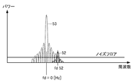
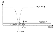
- FIG. 4 is a power spectrum of an anti-water echo signal component by a main lobe and a side lobe in a region B shown in FIG. 3 in one embodiment of the tide meter according to the present invention. It is explanatory drawing of the filter process in one Embodiment of the tide meter which concerns on this invention. It is a flowchart in one Embodiment of the tide meter which concerns on this invention. It is explanatory drawing of the filter process in the other aspect of one Embodiment of the tide meter which concerns on this invention.
- the tide meter 10 in the present embodiment includes a Doppler shift frequency measurement device 20, a tide calculation unit 11, and a display unit 12.
- the tide meter 10 includes a microcomputer (not shown) including a CPU (Central Processing Unit), a ROM (Read Only Memory), a RAM (Random Access Memory), and an input / output circuit to which various interfaces are connected.
- This microcomputer realizes the function of the tide meter 10 by causing a CPU to execute a control program stored in advance in a ROM.
- the tide meter 10 includes an operation unit (not shown), and the user can operate the operation unit to set a depth for measuring a tide, for example.
- the Doppler shift frequency measuring device 20 includes a transmission signal generation unit 21, a transmission amplifier 22, a transmission / reception switching unit 23, a transducer 24, a reception amplifier 25, an analog-digital converter (ADC) 26, a filter 27, and a frequency detection unit 28. Yes.
- ADC analog-digital converter
- the transmission signal generator 21 generates a transmission signal in the ultrasonic band and outputs it to the transmission amplifier 22 (22a to 22c).
- the transmission amplifier 22 (22a to 22c) amplifies the transmission signal generated by the transmission signal generation unit 21 with a predetermined amplification factor and outputs the amplified signal to the transmission / reception switching unit 23.
- the transmission / reception switching unit 23 (23a to 23c) switches between a transmission path from the transmission amplifier 22 to the transmitter / receiver 24 and a reception path from the transmitter / receiver 24 to the reception amplifier 25.
- the transmitter / receiver 24 (24a to 24c) is installed, for example, on the bottom of the ship and transmits ultrasonic waves.
- the transmitter / receiver 24 is arranged so that ultrasonic waves to be transmitted are transmitted into the sea at a certain depression angle so as to be at an angular interval of 120 degrees with respect to the horizontal direction.
- the transmitter / receiver 24 receives an echo signal in which the transmitted ultrasonic wave is reflected by an infinite number of scatterers in the sea and the sea floor, and outputs the echo signal to the reception amplifier 25 via the transmission / reception switching unit 23.
- the reception amplifier 25 (25a to 25c) amplifies the echo signal input from the transmitter / receiver 24 via the transmission / reception switching unit 23 with a predetermined amplification factor and outputs the amplified signal to the ADC 26.
- the ADC 26 (26a to 26c) converts an input analog value signal into a digital value signal and outputs the digital value signal to the filter 27.
- the filter 27 (27a to 27c) removes frequency components in the vicinity of the center frequency from the signal input from the ADC 26, with the frequency of the transmission signal generated by the transmission signal generation unit 21 as the center frequency.
- the filter 27 constitutes filter means according to the present invention.
- the frequency detector 28 (28a to 28c) detects the Doppler shift frequency of the echo signal due to the main lobe at the set depth from the output signal of the filter 27.
- the frequency detector 28 (28a to 28c) constitutes a Doppler shift frequency detector according to the present invention.
- the power flow calculation unit 11 includes a memory (not shown) that stores data of the Doppler shift frequency detected by the frequency detection unit 28. Further, the tidal current calculation unit 11 calculates the water vessel speed at the set depth set by the operation unit (not shown) based on the Doppler shift frequency detected by the frequency detection unit 28, calculates the ground vessel speed, The speed of the tidal current at the set depth is obtained based on the water ship speed and the ground ship speed. This tidal current calculation unit 11 constitutes a tidal current velocity calculating means according to the present invention.
- the display unit 12 is input with the data of the tidal velocity calculated by the tidal current calculating unit 11 and displays the tidal velocity on the screen.
- the transducer 24 transmits ultrasonic waves in three directions.
- the transducers 24a, 24b, and 24c transmit the main lobes 31, 32, and 33, respectively.
- the three main lobes 31 to 33 thus formed have an angular interval of 120 degrees and a predetermined depression angle ⁇ .
- the main lobe 31 is a main lobe heading in the bow direction.
- FIG. 3 is a diagram showing temporal changes in the signal intensity of the echo signal component due to the main lobe and the side lobe.
- the actual echo signal component is a combination of the main lobe and the side lobe, but in order to make the explanation easy to understand, FIG. 3 shows the signal intensity of the echo signal component by the main lobe and the side lobe individually.
- the echo signal 40 includes an echo signal component 41 (solid line) due to the main lobe and an echo signal component 42 (dotted line) due to the side lobe 34.
- the echo signal component 41 due to the main lobe includes an attenuation section 41a in which the anti-water echo signal component generated by reflection from plankton, which is a scatterer in seawater, gradually attenuates over time, and the transmission signal is reflected from the seabed. And a bottom reflection section 41b in which a ground echo signal component is generated.
- the echo signal component 42 by the side lobe 34 similarly includes an attenuation section 42a in which the anti-water echo signal component gradually attenuates over time, and a seabed reflection section 42b in which the ground echo signal component is generated. .
- the attenuation section 41a immediately before the seabed reflection section 41b is a section of seawater in the vicinity of the seabed (hereinafter referred to as “bottom tide”), and is therefore represented as a bottom tide section 41c.
- the bottom tide section 41c is, for example, a section corresponding to a water depth of about 70 m to 100 m if the seabed depth is 100 m.
- the illustrated range that is not affected by the echo by the side lobe 34 is the tidal current measurement possible range.
- FIG. 4 shows an example of the power spectrum of the water echo signal component by the main lobe in the region A where the depth is relatively deep in the tidal current measurable range shown in the figure.
- the water echo signal component 51 in this example has a Doppler shift frequency fd51 having a frequency higher than 0 Hz.
- the frequency detector 28 can easily detect the Doppler shift frequency fd51.
- FIG. 3 an example of the power spectrum of the water echo signal component in the region B is shown in FIG.
- the water echo signal component 52 due to the main lobe has a Doppler shift frequency fd52 having a frequency higher than 0 Hz.
- the frequency detector 28 cannot detect the Doppler shift frequency fd52 in this state.
- the water echo signal component 53 is due to the side lobe 34 whose main directing direction is substantially along the vertical direction, so that the center frequency thereof is a Doppler shift frequency of approximately 0 Hz. Become. That is, the center frequency of the water echo signal component 53 substantially matches the frequency of the ultrasonic signal transmitted by the transducer 24 (the frequency of the ultrasonic wave transmitted into the sea).
- the frequency detector 28 can detect the Doppler shift frequency fd52 when the tidal velocity has a certain speed. That is, the filter 27 can remove the received signal component due to the side lobe from the signal input from the ADC 26.
- the filter 27 is constituted by, for example, a band elimination filter or a band pass filter, and its filter characteristics (center frequency, filter attenuation characteristic, etc.) are set by an operation unit (not shown).
- the transmission signal generation unit 21 generates a transmission signal in the ultrasonic band (step S11) and outputs it to the transmission amplifier 22.
- the transmission amplifier 22 amplifies the transmission signal and outputs it to the wave transmitter / receiver 24 via the transmission / reception switching unit 23.
- the transmitter / receiver 24 transmits ultrasonic waves in the directions of the main lobes 31 to 33 shown in FIG. 2, for example (step S12).
- the transmitter / receiver 24 receives the reflected wave reflected from the object by the transmitted ultrasonic wave, outputs the signal to the receiving amplifier 25 via the transmission / reception switching unit 23, and the receiving amplifier 25 receives the reflected wave signal (step). S13).
- the ADC 26 converts the analog reception signal into a digital reception signal (step S14), and outputs it to the filter 27.
- the filter 27 performs the filtering process described with reference to FIG. 6 (step S15), and the received signal whose signal level of the water echo signal component 53 by the side lobe 34 is equal to or lower than the noise floor level is frequency. Output to the detection unit 28.
- the frequency detection unit 28 detects the Doppler shift frequency of the echo signal component due to the main lobes 31 to 33 at the set depth and the sea floor (step S16), and outputs the detected data to the tidal current calculation unit 11.
- the tidal current calculation unit 11 calculates the speed of the watercraft and the speed of the ground from the Doppler shift frequency according to the above [Equation 1], and calculates the speed of the tidal current at the set depth from the difference between the speed of the ground and the speed of the watercraft. (Step S17).
- the tidal current calculation unit 11 outputs the calculated tidal current velocity data to the display unit 12, and the display unit 12 displays the tidal current velocity data on the screen together with a numerical value indicating the set depth, for example.
- the tide speed is preferably displayed on the display unit 12 as less than 1 knot.
- the filter 27 can remove the echo signal component due to the side lobe, so that the main lobe directing direction and the vertical line are different from the conventional one.
- the Doppler shift frequency of the echo signal component due to the main lobe can be detected without reducing the angle formed. Therefore, the Doppler shift frequency measuring device 20 in the present embodiment can measure the Doppler shift frequency with higher accuracy than the conventional one.
- the tide meter 10 in the present embodiment is configured to include the Doppler shift frequency measurement device 20 that can measure the Doppler shift frequency with higher accuracy than the conventional one, the tide meter 10 has a higher accuracy than the conventional one. Can be calculated.
- the tide meter 10 according to the present embodiment can calculate the bottom tide velocity with high accuracy because the filter 27 removes the echo signal component due to the side lobe.
- the transmission signal generation unit 21 has been described by taking an example of generating a single-frequency transmission signal.
- a description will be given with reference to FIG.
- the transmission signal generation unit 21 generates a wideband transmission signal including signal components of different frequencies f1, f2, and f3.
- This type of transmission signal is generated by, for example, BPSK modulating a carrier wave having a constant frequency with a predetermined code.
- the filter 27 performs comb-type filter processing in which the vicinity of the frequencies at which the Doppler shift frequencies fd1, fd2, and fd3 are each 0 Hz is applied to each side of the signal components of the frequencies f1, f2, and f3.
- the echo signal components 61, 62, and 63 due to the lobe can be attenuated, and the echo signal components 71, 72, and 73 due to the main lobe can be extracted.
- the frequency detector 28 can detect the Doppler shift frequencies fd71, fd72, and fd73 of the echo signal components 71, 72, and 73 due to the main lobe.
- Tidal Current Meter 11 Tidal Current Calculation Unit (Tidal Current Speed Calculation Means) DESCRIPTION OF SYMBOLS 12 Display part 20 Doppler shift frequency measuring device 21 Transmission signal production
Landscapes
- Physics & Mathematics (AREA)
- Engineering & Computer Science (AREA)
- Acoustics & Sound (AREA)
- Radar, Positioning & Navigation (AREA)
- Remote Sensing (AREA)
- General Physics & Mathematics (AREA)
- Computer Networks & Wireless Communication (AREA)
- Multimedia (AREA)
- Aviation & Aerospace Engineering (AREA)
- Measurement Of Velocity Or Position Using Acoustic Or Ultrasonic Waves (AREA)
Abstract
【課題】従来のものよりも高精度でドップラシフト周波数を測定することができるドップラシフト周波数測定装置及びそれを備えた潮流計を提供する。 【解決手段】ドップラシフト周波数測定装置20は、予め定められた俯角の方向に向かうメインローブと、メインローブから所定角度で傘状に開き主要な指向方向が鉛直方向であるサイドローブとを有する超音波を水中に送信し、超音波のエコー信号を受信する送受波器24と、送受波器24が受信したエコー信号から超音波の周波数を中心周波数として予め定められた遮断帯域の信号成分を除去するフィルタ27と、遮断帯域の信号成分が除去されたエコー信号に含まれるメインローブによるエコー信号成分のドップラシフト周波数を検出する周波数検出部28と、を備える。
Description
本発明は、例えば、水中に送信された超音波のドップラシフト周波数を測定するドップラシフト周波数測定装置及びそれを備えた潮流計に関する。
従来、漁労援助や海洋調査を目的として潮流計で潮流が計測されている。潮流計は、船舶の船底に取り付けられており、例えば水平方向が互いに120度離れた方向に対して一定の俯角θで超音波を送受信する送受波器を備えている。この構成により、潮流計は、設定深度に位置する海中の無数の散乱体(プランクトン等)から帰来する反射波(対水エコー)に生じたドップラシフト周波数からその深度の潮流に対する船の速度(対水船速)を求める。また、潮流計は、海底からの反射波(対地エコー)に生じたドップラシフト周波数から海底に対する船の速度(対地船速)を求める。さらに、潮流計は、対地船速と対水船速との差から潮流の速度を求める。
ところで、この種の潮流計の指向特性は、俯角θの方向にメインローブを有し、メインローブから一定角度で傘状に開き鉛直方向に向かうサイドローブを有するものとなることが知られている。そのため、送受波器の受波信号は、特に海底近傍においてメインローブによる受波信号成分にサイドローブによる受波信号成分が加算されたものとなるので、この種の潮流計では海底近傍の潮流の速度を計測できないという課題があった。
この課題を解決するものとして、メインローブの指向方向と鉛直線とのなす角度を、サイドローブの指向方向と鉛直線とのなす角度より小さくすることにより、サイドローブによる水底反射波の強度をより低くしてメインローブによる水底の反射波を抽出できるようにした水中探知装置が提案されている(特許文献1参照)。
しかしながら、特許文献1記載のものでは、メインローブの指向方向と鉛直線とのなす角度が従前のものよりも小さくなるので、ドップラシフト周波数の測定精度が低下してしまい、その改善が望まれていた。
本発明は、前述のような事情に鑑みてなされたものであり、従来のものよりも高精度でドップラシフト周波数を測定することができるドップラシフト周波数測定装置及びそれを備えた潮流計を提供することを目的とする。
本発明のドップラシフト周波数測定装置は、予め定められた俯角の方向に向かうメインローブと、前記メインローブから所定角度で傘状に開き主要な指向方向が鉛直方向であるサイドローブとを有する超音波を水中に送信し、前記超音波のエコー信号を受信する送受波器と、前記送受波器が受信したエコー信号から前記超音波の周波数を中心周波数として予め定められた遮断帯域の信号成分を除去するフィルタ手段と、前記遮断帯域の信号成分が除去されたエコー信号に含まれる前記メインローブによるエコー信号成分のドップラシフト周波数を検出するドップラシフト周波数検出手段と、を備えた構成を有している。
この構成により、本発明のドップラシフト周波数測定装置は、フィルタ手段がサイドローブによるエコー信号成分を除去することができるので、従来のもののように、メインローブの指向方向と鉛直線とのなす角度を小さくすることなく、メインローブによるエコー信号成分のドップラシフト周波数を検出することができる。したがって、本発明のドップラシフト周波数測定装置は、従来のものよりも高精度でドップラシフト周波数を測定することができる。
本発明のドップラシフト周波数測定装置は、前記フィルタ手段は、前記サイドローブの超音波が水底で反射して生じたエコー信号成分を除去するものである構成を有している。
この構成により、本発明のドップラシフト周波数測定装置は、サイドローブによる水底からの信号強度が比較的強いエコー信号成分を除去することができる。
本発明のドップラシフト周波数測定装置は、前記ドップラシフト周波数検出手段は、前記メインローブの超音波が水底から予め定められた距離範囲内の水中にある散乱体で反射して生じたエコー信号成分のドップラシフト周波数を検出するものである構成を有している。
この構成により、本発明のドップラシフト周波数測定装置は、水底近傍の水中で発生したエコー信号成分のドップラシフト周波数を従来よりも高精度で検出することができる。
本発明のドップラシフト周波数測定装置は、前記送受波器が送信する超音波は、互いに異なる複数の周波数成分を有し、前記フィルタ手段は、前記各周波数成分の周波数を各中心周波数として予め定められた各遮断帯域の信号成分を除去するものであり、前記ドップラシフト周波数検出手段は、前記各遮断帯域の信号成分が除去されたエコー信号に含まれる前記メインローブによるエコー信号成分のドップラシフト周波数を検出するものである構成を有している。
この構成により、本発明のドップラシフト周波数測定装置は、複数の周波数成分を有する広帯域化された超音波を用いて、メインローブによるエコー信号成分のドップラシフト周波数を検出することができる。
本発明の潮流計は、ドップラシフト周波数測定装置と、海底に対する船の速度を示す対地船速と所定深度の潮流に対する船の速度を示す対水船速とを前記ドップラシフト周波数に基づいて求め、前記対地船速と前記対水船速との差から前記所定深度における潮流の速度を算出する潮流速度算出手段と、を備えた構成を有している。
この構成により、本発明の潮流計は、従来のものよりも高精度でドップラシフト周波数を測定することができるドップラシフト周波数測定装置を備えるので、従来のものよりも高精度で潮流の速度を算出することができる。
本発明は、従来のものよりも高精度でドップラシフト周波数を測定することができるという効果を有するドップラシフト周波数測定装置及びそれを備えた潮流計を提供することができるものである。
以下、本発明の実施形態について図面を用いて説明する。なお、本発明のドップラシフト周波数測定装置を潮流計に適用した例を挙げて説明する。
まず、本発明の一実施形態における潮流計の構成について説明する。
図1に示すように、本実施形態における潮流計10は、ドップラシフト周波数測定装置20、潮流算出部11、表示部12を備えている。
潮流計10は、図示しないCPU(Central Processing Unit)と、ROM(Read Only Memory)と、RAM(Random Access Memory)と、各種インタフェースが接続される入出力回路等を備えたマイクロコンピュータを含む。このマイクロコンピュータは、ROMに予め格納された制御プログラムをCPUに実行させることにより、潮流計10の機能を実現するようになっている。また、潮流計10は、図示しない操作部を備え、この操作部を利用者が操作することにより、例えば潮流を計測する深度の設定ができるようになっている。
ドップラシフト周波数測定装置20は、送信信号生成部21、送信アンプ22、送受信切替部23、送受波器24、受信アンプ25、アナログデジタルコンバータ(ADC)26、フィルタ27、周波数検出部28を備えている。
送信信号生成部21は、超音波帯域の送信信号を生成し、送信アンプ22(22a~22c)に出力するようになっている。
送信アンプ22(22a~22c)は、送信信号生成部21が生成した送信信号を所定増幅率で増幅し、送受信切替部23に出力するようになっている。
送受信切替部23(23a~23c)は、送信アンプ22から送受波器24に向かう送信時の経路と、送受波器24から受信アンプ25に向かう受信時の経路とを切り替えるようになっている。
送受波器24(24a~24c)は、例えば船底に設置され、超音波を送信するようになっている。この送受波器24は、送信する超音波が、水平方向に対して120度の角度間隔となるよう、かつ、一定の俯角で海中に送信されるよう配置されている。また、送受波器24は、送信した超音波が海中の無数の散乱体や海底で反射したエコー信号を受信し、送受信切替部23を介して受信アンプ25に出力するようになっている。
受信アンプ25(25a~25c)は、送受信切替部23を介して送受波器24から入力したエコー信号を所定増幅率で増幅し、ADC26に出力するようになっている。
ADC26(26a~26c)は、入力したアナログ値の信号をデジタル値の信号に変換してフィルタ27に出力するようになっている。
フィルタ27(27a~27c)は、ADC26から入力した信号に対し、送信信号生成部21が生成した送信信号の周波数を中心周波数として、その中心周波数近傍の周波数成分を除去するようになっている。このフィルタ27(27a~27c)は、本発明に係るフィルタ手段を構成する。
周波数検出部28(28a~28c)は、フィルタ27の出力信号から、設定深度におけるメインローブによるエコー信号のドップラシフト周波数を検出するようになっている。この周波数検出部28(28a~28c)は、本発明に係るドップラシフト周波数検出手段を構成する。
潮流算出部11は、周波数検出部28が検出したドップラシフト周波数のデータを記憶するメモリ(図示省略)を備えている。また、潮流算出部11は、周波数検出部28が検出したドップラシフト周波数に基づいて、図示しない操作部で設定された設定深度における対水船速を算出するとともに対地船速を算出し、さらに対水船速と対地船速とに基づいて設定深度における潮流の速度を求めるようになっている。この潮流算出部11は、本発明に係る潮流速度算出手段を構成する。
ここで、対水船速(又は対地船速)をv、ドップラシフト周波数をfd、水中音速をc、超音波の周波数をf0、俯角をθとすると、cはvよりも十分に大きいので、対水船速(又は対地船速)vは[数1]で近似される。
[数1]
v=fd・c/(2f0・cosθ)
v=fd・c/(2f0・cosθ)
表示部12は、潮流算出部11が算出した潮流の速度のデータを入力し、潮流の速度を画面に表示するようになっている。
次に、送受波器24が送信する超音波について図2の模式図を用いて説明する。
図2に示すように、送受波器24は、3方向に超音波を送信するようになっている。例えば、送受波器24a、24b及び24cは、それぞれ、メインローブ31、32及び33を送信するものである。形成された3つのメインローブ31~33は、互いに120度の角度間隔、かつ、予め定められた俯角θを有する。ここで、メインローブ31は、船首方向に向かうメインローブである。
送受波器24から3方向に超音波が送信されると、各メインローブ31~33から所定角度で傘状に開いたサイドローブ34が発生する。このサイドローブ34は、実際は単一方向に明確に指向するものではないが、送受波器24においては、海底での反射強度は鉛直方向(真下方向)が最も強くなるので、主要な指向方向が鉛直方向であるサイドローブ34が発生しているように表すことができる。
次に、送受波器24が送信した超音波が物体に反射して生じるエコー信号について図3~図6を用いて説明する。
図3は、メインローブ及びサイドローブによるエコー信号成分の信号強度の時間的な変化を示した図である。実際のエコー信号成分は、メインローブとサイドローブとの合成になるが、説明を分かりやすくするため、図3ではメインローブ及びサイドローブによるエコー信号成分の信号強度を個別に表している。
図3に示すように、エコー信号40は、メインローブによるエコー信号成分41(実線)と、サイドローブ34によるエコー信号成分42(点線)と、を含む。メインローブによるエコー信号成分41は、海水中の散乱体であるプランクトン等で反射して生じる対水エコー信号成分が時間の経過とともに徐々に減衰していく減衰区間41aと、送信信号が海底で反射して対地エコー信号成分が生じる海底反射区間41bと、を含む。一方、サイドローブ34によるエコー信号成分42は、同様に、対水エコー信号成分が時間の経過とともに徐々に減衰していく減衰区間42aと、対地エコー信号成分が生じる海底反射区間42bと、を含む。
図3において、海底反射区間41bの直前の減衰区間41aは、海底近傍の海水(以下「底潮」という。)の区間であるので、底潮区間41cとして表している。この底潮区間41cは、例えば、海底の深度が100mであれば70m~100m程度の水深に相当する区間である。
底潮区間41cでは、サイドローブ34による海底反射区間42bの対地エコー信号成分によりマスクされているので、従来の潮流計では、底潮区間41cの信号強度の測定は不可能であった。したがって、従来は、サイドローブ34によるエコーの影響を受けない図示の範囲が潮流計測可能範囲であった。
ここで、図示の潮流計測可能範囲において、深度が比較的深い領域Aにおけるメインローブによる対水エコー信号成分のパワースペクトルの一例を図4に示す。この例における対水エコー信号成分51は、0Hzよりも高い周波数のドップラシフト周波数fd51を有している。図4に示したように、この領域Aでは、サイドローブ34によるエコー信号成分の影響を受けないので、周波数検出部28は、ドップラシフト周波数fd51を容易に検出可能である。
一方、図3において、領域Bにおける対水エコー信号成分のパワースペクトルの一例を図5に示す。この例において、メインローブによる対水エコー信号成分52は、0Hzよりも高い周波数のドップラシフト周波数fd52を有している。しかしながら、この領域Bでは、図示のようにサイドローブ34による対水エコー信号成分53の影響を受けるので、この状態では、周波数検出部28は、ドップラシフト周波数fd52を検出不可能である。
ここで、対水エコー信号成分53は、図2に示したように、その主要な指向方向がほぼ鉛直方向に沿ったサイドローブ34によるものなので、その中心周波数は、ほぼ0Hzのドップラシフト周波数となる。すなわち、対水エコー信号成分53の中心周波数は、送受波器24が送信する超音波信号の周波数(海中に送信する超音波の周波数)にほぼ一致する。
したがって、フィルタ27の中心周波数を、送受波器24が送信する超音波信号の周波数に設定し、ドップラシフト周波数=0Hzの近傍を遮断帯域とするフィルタ処理を施すことにより、図6に示すように、サイドローブ34による対水エコー信号成分53を減衰させることができるので、周波数検出部28は、潮流の速度がある程度の速さを有する場合はドップラシフト周波数fd52を検出可能となる。すなわち、フィルタ27は、ADC26から入力した信号から、サイドローブによる受波信号成分を除去することができる。このフィルタ27は、例えば、帯域除去フィルタやバンドパスフィルタで構成され、そのフィルタ特性(中心周波数、フィルタ減衰特性等)が図示しない操作部により設定されるようになっている。
次に、本実施形態における潮流計10の動作について図7に示すフローチャートを中心に説明する。
送信信号生成部21は、超音波帯域の送信信号を生成し(ステップS11)、送信アンプ22に出力する。送信アンプ22は、送信信号を増幅し、送受信切替部23を介して送受波器24に出力する。
送受波器24は、例えば図2に示したメインローブ31~33の方向に超音波を送信する(ステップS12)。
送受波器24は、送信した超音波が物体で反射した反射波を受信し、その信号を送受信切替部23経由で受信アンプ25に出力し、受信アンプ25は反射波の信号を受信する(ステップS13)。
ADC26は、アナログ値の受信信号をデジタル値の受信信号に変換し(ステップS14)、フィルタ27に出力する。
フィルタ27は、図6を用いて説明したフィルタ処理を施し(ステップS15)、サイドローブ34による対水エコー信号成分53の信号レベルがノイズフロアのレベルと同等又はそれ以下となった受信信号を周波数検出部28に出力する。
周波数検出部28は、設定深度及び海底におけるメインローブ31~33によるエコー信号成分のドップラシフト周波数を検出し(ステップS16)、検出したデータを潮流算出部11に出力する。
潮流算出部11は、前述の[数1]により、ドップラシフト周波数から対水船速及び対地船速を算出し、対地船速と対水船速との差から設定深度における潮流の速度を算出する(ステップS17)。潮流算出部11は、算出した潮流の速度データを表示部12に出力し、表示部12は、例えば、設定深度を示す数値とともに潮流の速度データを画面に表示する。
なお、潮流算出部11は、底潮の速度が低速である場合(ドップラシフト周波数がゼロに近い場合)には、底潮の速度を算出することは困難となるが、その場合は、例えば底潮の速度を1ノット未満として表示部12に表示させるのが好ましい。この構成により、潮流計10は、底潮に関する情報を全く提供できないシステムよりも、有益な情報をユーザに提供することができる。
以上のように、本実施形態におけるドップラシフト周波数測定装置20は、フィルタ27がサイドローブによるエコー信号成分を除去することができるので、従来のもののように、メインローブの指向方向と鉛直線とのなす角度を小さくすることなく、メインローブによるエコー信号成分のドップラシフト周波数を検出することができる。したがって、本実施形態におけるドップラシフト周波数測定装置20は、従来のものよりも高精度でドップラシフト周波数を測定することができる。
また、本実施形態における潮流計10は、従来のものよりも高精度でドップラシフト周波数を測定することができるドップラシフト周波数測定装置20を備える構成としたので、従来のものよりも高精度で潮流の速度を算出することができる。特に、本実施形態における潮流計10は、フィルタ27がサイドローブによるエコー信号成分を除去するので、底潮の速度を高精度で算出することができる。
(他の態様)
前述の実施形態では、送信信号生成部21が、単一周波数の送信信号を生成する例を挙げて説明したが、広帯域化した送信信号を生成する構成としてもよい。以下、図8を用いて説明する。
前述の実施形態では、送信信号生成部21が、単一周波数の送信信号を生成する例を挙げて説明したが、広帯域化した送信信号を生成する構成としてもよい。以下、図8を用いて説明する。
図8に示すように、送信信号生成部21が、互いに異なる周波数f1、f2、f3の信号成分を含む広帯域の送信信号を生成するものとする。この種の送信信号は、例えば、一定周波数の搬送波を所定のコードによりBPSK変調することにより生成される。
この場合、フィルタ27は、ドップラシフト周波数fd1、fd2、fd3がそれぞれ0Hzとなる周波数の近傍を各遮断帯域とする櫛型のフィルタ処理を施すことにより、周波数f1、f2、f3の信号成分のサイドローブによるエコー信号成分61、62、63を減衰させ、メインローブによるエコー信号成分71、72、73を取り出すことができる。
その結果、周波数検出部28は、メインローブによるエコー信号成分71、72、73のドップラシフト周波数fd71、fd72、fd73を検出することができる。
10 潮流計
11 潮流算出部(潮流速度算出手段)
12 表示部
20 ドップラシフト周波数測定装置
21 送信信号生成部
22(22a~22c) 送信アンプ
23(23a~23c) 送受信切替部
24(24a~24c) 送受波器
25(25a~25c) 受信アンプ
26(26a~26c) ADC
27(27a~27c) フィルタ(フィルタ手段)
28(28a~28c) 周波数検出部(ドップラシフト周波数検出手段)
31~33 メインローブ
34 サイドローブ
11 潮流算出部(潮流速度算出手段)
12 表示部
20 ドップラシフト周波数測定装置
21 送信信号生成部
22(22a~22c) 送信アンプ
23(23a~23c) 送受信切替部
24(24a~24c) 送受波器
25(25a~25c) 受信アンプ
26(26a~26c) ADC
27(27a~27c) フィルタ(フィルタ手段)
28(28a~28c) 周波数検出部(ドップラシフト周波数検出手段)
31~33 メインローブ
34 サイドローブ
Claims (5)
- 予め定められた俯角の方向に向かうメインローブと、前記メインローブから所定角度で傘状に開き主要な指向方向が鉛直方向であるサイドローブとを有する超音波を水中に送信し、前記超音波のエコー信号を受信する送受波器と、
前記送受波器が受信したエコー信号から前記超音波の周波数を中心周波数として予め定められた遮断帯域の信号成分を除去するフィルタ手段と、
前記遮断帯域の信号成分が除去されたエコー信号に含まれる前記メインローブによるエコー信号成分のドップラシフト周波数を検出するドップラシフト周波数検出手段と、
を備えたことを特徴とするドップラシフト周波数測定装置。 - 前記フィルタ手段は、前記サイドローブの超音波が水底で反射して生じたエコー信号成分を除去するものであることを特徴とする請求項1に記載のドップラシフト周波数測定装置。
- 前記ドップラシフト周波数検出手段は、前記メインローブの超音波が水底から予め定められた距離範囲内の水中にある散乱体で反射して生じたエコー信号成分のドップラシフト周波数を検出するものであることを特徴とする請求項1又は請求項2に記載のドップラシフト周波数測定装置。
- 前記送受波器が送信する超音波は、互いに異なる複数の周波数成分を有し、
前記フィルタ手段は、前記各周波数成分の周波数を各中心周波数として予め定められた各遮断帯域の信号成分を除去するものであり、
前記ドップラシフト周波数検出手段は、前記各遮断帯域の信号成分が除去されたエコー信号に含まれる前記メインローブによるエコー信号成分のドップラシフト周波数を検出するものであることを特徴とする請求項1から請求項3までのいずれか1項に記載のドップラシフト周波数測定装置。 - 請求項1から請求項4までのいずれか1項に記載のドップラシフト周波数測定装置と、
海底に対する船の速度を示す対地船速と所定深度の潮流に対する船の速度を示す対水船速とを前記ドップラシフト周波数に基づいて求め、前記対地船速と前記対水船速との差から前記所定深度における潮流の速度を算出する潮流速度算出手段と、
を備えたことを特徴とする潮流計。
Priority Applications (1)
| Application Number | Priority Date | Filing Date | Title |
|---|---|---|---|
| JP2015522657A JP6403669B2 (ja) | 2013-06-11 | 2014-05-13 | 潮流計 |
Applications Claiming Priority (2)
| Application Number | Priority Date | Filing Date | Title |
|---|---|---|---|
| JP2013-122307 | 2013-06-11 | ||
| JP2013122307 | 2013-06-11 |
Publications (1)
| Publication Number | Publication Date |
|---|---|
| WO2014199758A1 true WO2014199758A1 (ja) | 2014-12-18 |
Family
ID=52022059
Family Applications (1)
| Application Number | Title | Priority Date | Filing Date |
|---|---|---|---|
| PCT/JP2014/062663 Ceased WO2014199758A1 (ja) | 2013-06-11 | 2014-05-13 | ドップラシフト周波数測定装置及びそれを備えた潮流計 |
Country Status (2)
| Country | Link |
|---|---|
| JP (1) | JP6403669B2 (ja) |
| WO (1) | WO2014199758A1 (ja) |
Cited By (8)
| Publication number | Priority date | Publication date | Assignee | Title |
|---|---|---|---|---|
| CN104865404A (zh) * | 2015-06-17 | 2015-08-26 | 王三名 | 一种声学多普勒流速测量仪和流速测量方法 |
| JP2016217958A (ja) * | 2015-05-25 | 2016-12-22 | 古野電気株式会社 | ドップラシフト周波数測定装置、対水速度計、及び潮流計 |
| CN106370886A (zh) * | 2016-08-30 | 2017-02-01 | 厦门博意达科技有限公司 | 微探头超声波多普勒流速仪的控制电路及信号处理方法 |
| EP3401700A4 (en) * | 2015-09-16 | 2019-05-22 | Furuno Electric Co., Ltd. | VEHICLE SPEED METER AND METHOD FOR OBTAINING A VESSEL SPEED |
| WO2020037452A1 (zh) * | 2018-08-20 | 2020-02-27 | 深圳市大疆创新科技有限公司 | 频点偏移的估计方法、装置、无人机及遥控器 |
| CN112415223A (zh) * | 2020-11-19 | 2021-02-26 | 中国科学院大学 | 一种液态金属内部的速度测量方法、装置及存储介质 |
| CN114152774A (zh) * | 2021-12-06 | 2022-03-08 | 中国科学院大学 | 液体流场的流速测量方法、装置、电子设备及存储介质 |
| CN115015576A (zh) * | 2022-06-28 | 2022-09-06 | 中国海洋大学 | 一种时频同步原理的海流及海流计三维运动速度测量方法 |
Citations (3)
| Publication number | Priority date | Publication date | Assignee | Title |
|---|---|---|---|---|
| JPH03242583A (ja) * | 1990-02-20 | 1991-10-29 | Furuno Electric Co Ltd | 水中探知装置 |
| JPH08136642A (ja) * | 1994-11-11 | 1996-05-31 | Nec Corp | 境界面監視ソナー |
| JP2007064768A (ja) * | 2005-08-30 | 2007-03-15 | Furuno Electric Co Ltd | 水中探知装置 |
Family Cites Families (4)
| Publication number | Priority date | Publication date | Assignee | Title |
|---|---|---|---|---|
| JPS61173182A (ja) * | 1985-01-28 | 1986-08-04 | Furuno Electric Co Ltd | 広範囲角水中探知装置に用いる指向性ビ−ム形成方法 |
| JPS63152580U (ja) * | 1987-11-19 | 1988-10-06 | ||
| US5177710A (en) * | 1992-01-31 | 1993-01-05 | Westinghouse Electric Corp. | High speed multibeam sidelock sonar with few elements |
| JP5409452B2 (ja) * | 2010-03-15 | 2014-02-05 | 古野電気株式会社 | 探知装置 |
-
2014
- 2014-05-13 WO PCT/JP2014/062663 patent/WO2014199758A1/ja not_active Ceased
- 2014-05-13 JP JP2015522657A patent/JP6403669B2/ja not_active Expired - Fee Related
Patent Citations (3)
| Publication number | Priority date | Publication date | Assignee | Title |
|---|---|---|---|---|
| JPH03242583A (ja) * | 1990-02-20 | 1991-10-29 | Furuno Electric Co Ltd | 水中探知装置 |
| JPH08136642A (ja) * | 1994-11-11 | 1996-05-31 | Nec Corp | 境界面監視ソナー |
| JP2007064768A (ja) * | 2005-08-30 | 2007-03-15 | Furuno Electric Co Ltd | 水中探知装置 |
Cited By (10)
| Publication number | Priority date | Publication date | Assignee | Title |
|---|---|---|---|---|
| JP2016217958A (ja) * | 2015-05-25 | 2016-12-22 | 古野電気株式会社 | ドップラシフト周波数測定装置、対水速度計、及び潮流計 |
| US10175262B2 (en) | 2015-05-25 | 2019-01-08 | Furuno Electric Co., Ltd. | Doppler shift frequency measuring device, log speed meter and tidal current meter |
| CN104865404A (zh) * | 2015-06-17 | 2015-08-26 | 王三名 | 一种声学多普勒流速测量仪和流速测量方法 |
| EP3401700A4 (en) * | 2015-09-16 | 2019-05-22 | Furuno Electric Co., Ltd. | VEHICLE SPEED METER AND METHOD FOR OBTAINING A VESSEL SPEED |
| CN106370886A (zh) * | 2016-08-30 | 2017-02-01 | 厦门博意达科技有限公司 | 微探头超声波多普勒流速仪的控制电路及信号处理方法 |
| WO2020037452A1 (zh) * | 2018-08-20 | 2020-02-27 | 深圳市大疆创新科技有限公司 | 频点偏移的估计方法、装置、无人机及遥控器 |
| CN112415223A (zh) * | 2020-11-19 | 2021-02-26 | 中国科学院大学 | 一种液态金属内部的速度测量方法、装置及存储介质 |
| CN112415223B (zh) * | 2020-11-19 | 2021-09-24 | 中国科学院大学 | 一种液态金属内部的速度测量方法、装置及存储介质 |
| CN114152774A (zh) * | 2021-12-06 | 2022-03-08 | 中国科学院大学 | 液体流场的流速测量方法、装置、电子设备及存储介质 |
| CN115015576A (zh) * | 2022-06-28 | 2022-09-06 | 中国海洋大学 | 一种时频同步原理的海流及海流计三维运动速度测量方法 |
Also Published As
| Publication number | Publication date |
|---|---|
| JP6403669B2 (ja) | 2018-10-10 |
| JPWO2014199758A1 (ja) | 2017-02-23 |
Similar Documents
| Publication | Publication Date | Title |
|---|---|---|
| JP6403669B2 (ja) | 潮流計 | |
| US8864671B2 (en) | Methods and systems for color flow imaging | |
| JP2007507691A (ja) | ソナー・システムおよびプロセス | |
| RU2488133C1 (ru) | Гидроакустический комплекс для обнаружения движущегося источника звука, измерения азимутального угла на источник и горизонта источника звука в мелком море | |
| KR102374304B1 (ko) | 미식별 수중신호 위치의 추정 방법 및 시스템 | |
| RU2474836C1 (ru) | Гидроакустический комплекс для измерения азимутального угла на источник звука в мелком море | |
| KR20170029899A (ko) | 능동 소나 시스템의 lfm신호 파라미터 추정 장치 및 방법 | |
| JP5235737B2 (ja) | パルスドップラレーダ装置 | |
| JP2012247304A (ja) | 短時間信号のピークパワースペクトルを検出する方法及び装置 | |
| RU2541699C1 (ru) | Гидроакустический способ измерения дистанции с помощью взрывного источника | |
| RU2602759C1 (ru) | Способ автоматического обнаружения и классификации объекта в водной среде | |
| JP6347660B2 (ja) | 魚群探知機、単体魚検出方法、および単体魚検出プログラム | |
| KR100979286B1 (ko) | 수중 거리 및 방위를 측정하는 장치 및 방법 | |
| RU2510608C1 (ru) | Способ измерения толщины льда с подводного носителя | |
| RU2541435C1 (ru) | Способ определения осадки айсберга | |
| RU2650419C1 (ru) | Гидролокационный способ классификации подводных объектов в контролируемой акватории | |
| JP6610224B2 (ja) | バイスタティックアクティブソーナー装置およびその受信器 | |
| RU2655019C1 (ru) | Способ измерения скорости судна доплеровским лагом | |
| JP7638582B2 (ja) | 境界音響反射に基づくターゲット強度自己測定方法及びターゲット強度自己測定システム | |
| RU2476899C1 (ru) | Гидроакустический комплекс для измерения азимутального угла и горизонта источника звука в мелком море | |
| RU85001U1 (ru) | Допплеровский акустический локатор для мониторинга поля ветра и турбулентности в атмосферном пограничном слое | |
| KR101091645B1 (ko) | 도플러 편이 추정장치 및 도플러 편이 추정방법 | |
| JP2014020907A (ja) | 水中探知装置、水中探知方法、及びプログラム | |
| RU2590932C1 (ru) | Гидроакустический способ измерения глубины погружения неподвижного объекта | |
| KR101158792B1 (ko) | 신호의 믹싱기법을 이용한 코히어런트 도플러 유속분포 측정 방법 및 장치 |
Legal Events
| Date | Code | Title | Description |
|---|---|---|---|
| 121 | Ep: the epo has been informed by wipo that ep was designated in this application |
Ref document number: 14811272 Country of ref document: EP Kind code of ref document: A1 |
|
| ENP | Entry into the national phase |
Ref document number: 2015522657 Country of ref document: JP Kind code of ref document: A |
|
| NENP | Non-entry into the national phase |
Ref country code: DE |
|
| 122 | Ep: pct application non-entry in european phase |
Ref document number: 14811272 Country of ref document: EP Kind code of ref document: A1 |