WO2014199699A1 - 音声信号振幅抑圧装置 - Google Patents
音声信号振幅抑圧装置 Download PDFInfo
- Publication number
- WO2014199699A1 WO2014199699A1 PCT/JP2014/058601 JP2014058601W WO2014199699A1 WO 2014199699 A1 WO2014199699 A1 WO 2014199699A1 JP 2014058601 W JP2014058601 W JP 2014058601W WO 2014199699 A1 WO2014199699 A1 WO 2014199699A1
- Authority
- WO
- WIPO (PCT)
- Prior art keywords
- amplitude
- signal
- cut filter
- low
- output
- Prior art date
- Legal status (The legal status is an assumption and is not a legal conclusion. Google has not performed a legal analysis and makes no representation as to the accuracy of the status listed.)
- Ceased
Links
Images

Classifications
-
- H—ELECTRICITY
- H04—ELECTRIC COMMUNICATION TECHNIQUE
- H04R—LOUDSPEAKERS, MICROPHONES, GRAMOPHONE PICK-UPS OR LIKE ACOUSTIC ELECTROMECHANICAL TRANSDUCERS; ELECTRIC HEARING AIDS; PUBLIC ADDRESS SYSTEMS
- H04R25/00—Electric hearing aids
- H04R25/35—Electric hearing aids using translation techniques
- H04R25/356—Amplitude, e.g. amplitude shift or compression
-
- H—ELECTRICITY
- H03—ELECTRONIC CIRCUITRY
- H03G—CONTROL OF AMPLIFICATION
- H03G11/00—Limiting amplitude; Limiting rate of change of amplitude
- H03G11/02—Limiting amplitude; Limiting rate of change of amplitude by means of diodes
-
- H—ELECTRICITY
- H03—ELECTRONIC CIRCUITRY
- H03G—CONTROL OF AMPLIFICATION
- H03G11/00—Limiting amplitude; Limiting rate of change of amplitude
- H03G11/04—Limiting level dependent on strength of signal; Limiting level dependent on strength of carrier on which signal is modulated
-
- H—ELECTRICITY
- H03—ELECTRONIC CIRCUITRY
- H03G—CONTROL OF AMPLIFICATION
- H03G9/00—Combinations of two or more types of control, e.g. gain control and tone control
- H03G9/02—Combinations of two or more types of control, e.g. gain control and tone control in untuned amplifiers
- H03G9/12—Combinations of two or more types of control, e.g. gain control and tone control in untuned amplifiers having semiconductor devices
- H03G9/18—Combinations of two or more types of control, e.g. gain control and tone control in untuned amplifiers having semiconductor devices for tone control and volume expansion or compression
-
- H—ELECTRICITY
- H04—ELECTRIC COMMUNICATION TECHNIQUE
- H04R—LOUDSPEAKERS, MICROPHONES, GRAMOPHONE PICK-UPS OR LIKE ACOUSTIC ELECTROMECHANICAL TRANSDUCERS; ELECTRIC HEARING AIDS; PUBLIC ADDRESS SYSTEMS
- H04R1/00—Details of transducers, loudspeakers or microphones
- H04R1/10—Earpieces; Attachments therefor ; Earphones; Monophonic headphones
- H04R1/1041—Mechanical or electronic switches, or control elements
-
- H—ELECTRICITY
- H04—ELECTRIC COMMUNICATION TECHNIQUE
- H04R—LOUDSPEAKERS, MICROPHONES, GRAMOPHONE PICK-UPS OR LIKE ACOUSTIC ELECTROMECHANICAL TRANSDUCERS; ELECTRIC HEARING AIDS; PUBLIC ADDRESS SYSTEMS
- H04R25/00—Electric hearing aids
- H04R25/35—Electric hearing aids using translation techniques
- H04R25/353—Frequency, e.g. frequency shift or compression
-
- H—ELECTRICITY
- H04—ELECTRIC COMMUNICATION TECHNIQUE
- H04R—LOUDSPEAKERS, MICROPHONES, GRAMOPHONE PICK-UPS OR LIKE ACOUSTIC ELECTROMECHANICAL TRANSDUCERS; ELECTRIC HEARING AIDS; PUBLIC ADDRESS SYSTEMS
- H04R2225/00—Details of deaf aids covered by H04R25/00, not provided for in any of its subgroups
- H04R2225/43—Signal processing in hearing aids to enhance the speech intelligibility
-
- H—ELECTRICITY
- H04—ELECTRIC COMMUNICATION TECHNIQUE
- H04R—LOUDSPEAKERS, MICROPHONES, GRAMOPHONE PICK-UPS OR LIKE ACOUSTIC ELECTROMECHANICAL TRANSDUCERS; ELECTRIC HEARING AIDS; PUBLIC ADDRESS SYSTEMS
- H04R2430/00—Signal processing covered by H04R, not provided for in its groups
- H04R2430/01—Aspects of volume control, not necessarily automatic, in sound systems
-
- H—ELECTRICITY
- H04—ELECTRIC COMMUNICATION TECHNIQUE
- H04R—LOUDSPEAKERS, MICROPHONES, GRAMOPHONE PICK-UPS OR LIKE ACOUSTIC ELECTROMECHANICAL TRANSDUCERS; ELECTRIC HEARING AIDS; PUBLIC ADDRESS SYSTEMS
- H04R2430/00—Signal processing covered by H04R, not provided for in its groups
- H04R2430/03—Synergistic effects of band splitting and sub-band processing
Definitions
- the present invention relates to an audio signal amplitude suppression device for converting a sound signal into a signal suitable for sound reproduction by an earphone or a headphone.
- the present invention relates to a technique for processing an audio signal into a form in which a reproduced sound with a high degree of intelligibility can be obtained with less burden on the ear and the reproduction device.
- the method has a limit in the ability to eliminate harmful signals while leaving the necessary signals, and there is a problem that it is difficult to secure good frequency characteristics in a high frequency band.
- problems such as noise, intelligibility, blockage, and pressure.
- the present inventor made the following discovery in the process of developing a hearing aid. That is, the sensitivity of the ear changes depending on the environmental sound of high frequency (high frequency components generally considered as environmental noise), and the sensitivity of the ear decreases when the environmental sound is large or strong, and increases when it is weak. It is. For this reason, when a sound in which only this environmental sound is erased or weakened is added to the ear, a low frequency sound is heard unnaturally and causes a sense of obstruction or pressure.
- high frequency high frequency components generally considered as environmental noise
- high-frequency environmental sounds have a great impact on the sense of openness and realism. It is known that the sound of bone conduction headphones is easy to hear when earplugs are used in combination. This is partly because the earplugs block high-frequency environmental sounds and increase the ear sensitivity.
- earphones and headphones (generally referred to as noise canceling earphones) that have the function of making it difficult to hear surrounding sounds have become widespread. This is because environmental sounds, particularly high frequency environmental sounds, cannot be heard.
- the degree of comprehension changes when the volume is changed while the sound collected by the microphone is reproduced with good frequency characteristics using earphones and headphones.
- the volume of the words does not change so much, but the environmental sound suddenly feels low, and the degree of intelligibility is highest in this vicinity. This phenomenon is thought to be closely related to the ability of the ears to hear words even in noise.
- Amplitude restrictions are applied to sound signals of television, radio broadcasting, or commercially available music software.
- the purpose is mainly to avoid problems due to the lack of capacity of the audio equipment, but this amplitude limitation has also yielded favorable results for earphone and headphone playback at low frequencies.
- effective amplitude limitation for reproducing earphones and headphones is not performed at high frequencies. For this reason, when these signals are heard using earphones or headphones having flat frequency characteristics, high sounds are heard too strong. (Healthy human ears are thought to have appropriate amplitude limits on incoming sound, but it is unclear why this mechanism and why the amplitude limit function does not work when using earphones or headphones.)
- the reproduced sound from the earphones and headphones tends to be uncomfortable. “When hearing aids are used, noise is uncomfortable and words from distant sound sources cannot be heard” and “distant sound words cannot be heard even when recorded sound is played back”. The high frequency gain of the earphones and headphones is low. to cause. In other words, this problem does not occur if the amplitude limitation suitable for earphone or headphone reproduction and reproduction of uniform gain characteristics at any frequency are performed.
- the signal picked up by the microphone is amplified as it is and put into the ear. Improve this. It also creates sound playback signals that can use the capabilities of the equipment with high efficiency.
- the present invention is characterized in that the low frequency band is subjected to amplitude limitation or amplitude suppression by a method with little information loss, and the high frequency is left as it is, slice-type amplitude limitation, cut, or pseudo sound is added. Specifically, the following means are adopted.
- the amplitude suppression device is a device that limits the amplitude to a certain range and cuts the amplitude outside the range, and the input signal having a large value is attenuated and output without being cut out of the signal outside the range. Including both devices.
- the burden on the ear is small, and a reproduced sound with high intelligibility can be obtained with natural sound quality, which greatly improves the performance of a device for hearing loss or a recorder. I can do it.
- a relatively large volume can be obtained even with a small-output acoustic device, there is a great effect in reducing the size and performance of the acoustic device.
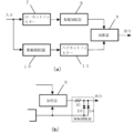
- FIG. 3A is an overall block diagram
- FIG. 3B is a block diagram (partial circuit diagram) in which an amplitude limiter is added after an adder in the third embodiment.
- Block diagram (partial circuit diagram) of a fourth embodiment of the present invention Block diagram of a fifth embodiment of the present invention
- Block diagram (partial circuit diagram) of sixth embodiment of the present invention Block diagram of a seventh embodiment of the present invention
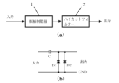
- FIG. 1A is a block diagram of a first embodiment of the present invention, and this embodiment has a high utility value for a device (such as a telephone) that does not require a high frequency signal.
- the amplitude suppressor according to the present embodiment includes an amplitude limiter 1 that inputs an audio signal, and a high-cut filter 2 that is connected to the output side thereof and outputs an audio signal after amplitude limitation.
- the amplitude limiter 1 is an amplitude limiter equivalent to that used in FIG. 10 of Japanese Patent No. 4976012 and a part of JP2011 − 1666652.
- an amplitude limiter hereinafter referred to as a bias shift type amplitude limiter
- the circuit is as shown in FIG.
- the DC potential of the cathode of the diode D1 or the anode of the diode D2 is 0 V, which is the same as GND.
- an amplitude signal larger than the forward voltage of the diode D1 or the diode D2 is input to the input, a current flows through the diode D1 or D2 and the capacitor C, the output signal amplitude is limited, and the capacitor C is charged. .
- This charging generates a voltage across the capacitor C.
- This voltage becomes the bias voltage of the output side circuit. That is, the amplitude is limited by changing the bias voltage of the output circuit by a large input signal. In this amplitude limiting method, information loss in a portion exceeding the limited amplitude is small, but distortion signals that deteriorate the reproduced sound quality are often generated.
- the high cut filter 2 removes high frequency components from the output signal of the amplitude limiter 1. Therefore, if a signal having a frequency higher than 4 KHz is deleted by the high cut filter 2, the output signal of the high cut filter 2 does not include a signal that significantly deteriorates the reproduction sound quality (discomfort to the ear in the sound distortion).
- the main cause is a frequency component higher than about 4 KHz). However, the frequency component lower than 4 kHz of the input signal is output as it is. Therefore, it is practical although it is simple for a device that does not require a signal of 4 kHz or higher.
- a slice type amplitude limiter that does not affect the sound quality is provided in the previous stage of this circuit, the generation of unpleasant sound signals generated by the bias shift type amplitude limiter can be reduced. That is, when a signal including a signal having a large variation in amplitude value is subjected to bias shift type amplitude limitation, a large signal causing unpleasant noise is randomly generated and is difficult to be removed by a high-cut filter in the next stage because it is random. However, when a signal whose level of a large signal is aligned by the slice type amplitude limit is subjected to the bias shift type amplitude limit, the bias shift is performed in the opposite direction by the same amount. Is done.
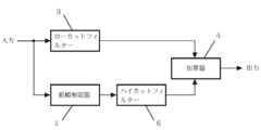
- FIG. 2 is a block diagram of the second embodiment of the present invention, which is highly useful when it is desired to obtain as much reproduced sound as possible with an acoustic system using a small output amplifier and small speakers.
- FIG. 1 is not suitable for a device that requires a high frequency signal such as for music, but in this embodiment, a high frequency signal is not deleted, so that a good frequency characteristic can be obtained even for music.
- the low cut filter 3 extracts only a high frequency signal from the input signal.
- the high frequency signal is added by the adder 4 with the low frequency signal generated by the amplitude limiter 5 and the high cut filter 6.
- the output signal of the low cut filter 3 does not include a signal that deteriorates the reproduction sound quality. Further, the output of the high cut filter 6 does not include a signal that significantly deteriorates the reproduction sound quality. Accordingly, the output signal of the adder 4 obtained by adding these two signals does not include a signal that greatly deteriorates the reproduction sound quality.
- the high frequency signal amplitude of the output of the adder 4 is not limited, when a very strong amplitude limitation is performed by the amplitude limiter 5 and the high cut filter 6 of the low frequency circuit, the high frequency signal amplitude is higher than the low frequency signal amplitude.
- the signal amplitude of the area becomes relatively large.
- the amplitude of the high frequency signal is small. Thus, if used for less severe amplitude limiting, this configuration with no high frequency signal amplitude limiting will not cause much problems.
- FIG. 3A is a block diagram of the third embodiment of the present invention, which has high utility value for an audio device such as a hearing aid or a recording device that mainly reproduces sound using earphones or headphones.
- an amplitude limiter 8 is added after the low-cut filter 7 constituting the high-frequency circuit of the second embodiment.
- a high-frequency large-amplitude input signal appears as it is in the output. Disadvantages are eliminated.
- the amplitude limiter 8 limits the amplitude of the output signal (high frequency signal) of the low cut filter 7, an excessive amplitude signal does not appear at the output of the adder 9.
- the amplitude limiter 8 can obtain a better result with a general amplitude limiter (slice type) than with a bias shift type. The reason for this is that even if information exceeding the limit value is lost in a high-frequency signal, the effect on the playback sound is less, and the slice-type amplitude limiter is worse than the bias-shift type amplitude limiter. This is because less distortion signal is generated.
- the reason why the high frequency signal is processed separately from the low frequency signal is that when the high frequency signal is processed by the same method as the low frequency signal, distortion that causes unpleasant noise is often generated.
- the slice-type amplitude limiter 8 can be provided after the adder 9.
- the amplitude limit value should be smaller as the signal frequency is higher. In order to obtain a signal having such characteristics, it is effective to input a signal in which the high frequency is emphasized and attenuate the high frequency of the output signal.
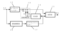
- FIG. 4 is a block diagram (partially circuit diagram) of the fourth embodiment of the present invention. Similar to the third embodiment, it is applied to an audio device such as a hearing aid or a recorder that reproduces sound mainly by earphones or headphones. High utility value.
- an inverter 14 that takes in and inverts an output signal from the high-cut filter 17 of the low-frequency circuit and supplies it to the amplitude limit reference potential circuit of the amplitude limiter 13 of the high-frequency circuit is added to the third embodiment. It is a configuration. That is, in the present embodiment, the output of the high cut filter 17 is branched to the adder 15 and the inverter 14, and the output from the inverter 14 is used as a reference for the parallel diodes D 5 and D 6 constituting the amplitude limiter 13. Connect to the voltage application side.
- the amplitude limiter 13 uses the amplitude limit of the high frequency band signal output from the low cut filter 12 as a reference and the inverted signal of the low frequency band signal that has been output from the high cut filter 17 as a reference. Limit the amplitude.
- the adder 15 adds the high frequency band signal whose amplitude is limited by the amplitude limiter 13 and the low frequency band signal from the high cut filter 17 and outputs the result.
- the output signal amplitude value of the adder 9 is the output amplitude value of the high cut filter 11 + the output amplitude value of the amplitude limiter 8. That is, if the maximum output amplitude of the high cut filter 11 and the maximum output amplitude of the amplitude limiter 8 are the same, the maximum output amplitude of the adder 9 is twice the maximum output amplitude of the high cut filter 11 or the waveform is deformed due to the amplitude limitation. A little bigger. However, considering the purpose of amplitude limitation, it is preferable that the maximum amplitude value of the adder 9 does not always exceed the maximum amplitude of the high cut filter 11.
- the inverter 14 of FIG. 4 is provided for this purpose.
- the maximum output amplitude value of the adder 15 does not exceed the maximum amplitude output value of the high cut filter 17. Therefore, the output signal having this configuration can obtain a large reproduced sound even when the maximum amplitude is smaller than that in FIG. This is also preferable as an excessive sound suppression characteristic.
- the maximum output amplitude in the case of FIG. 3 is “maximum output amplitude of the amplitude limiter 8 + maximum output amplitude of the high cut filter 11”. However, since the maximum output amplitude in FIG.
- the maximum output amplitude of the amplitude limiter 13 is dynamically controlled so that the maximum amplitude of the adder 15 does not exceed the maximum amplitude value of the high cut filter 17.
- FIG. 5 is a block diagram of a fifth embodiment of the present invention, which is highly useful for audio equipment that reproduces sound using earphones or headphones, particularly for hearing aids, as in the third and fourth embodiments.
- This embodiment is a modification of FIG. 3, and the amplitude limiter 10 of FIG. 3 is replaced with a low-frequency attenuator 21.
- the configuration of FIG. 3 is superior in terms of the amplitude limiting effect, but FIG. 5 is superior in terms of sound distortion.
- the amplitude of a sound wave is larger as the frequency is lower, and conversely, it is smaller when the frequency is higher, and the difference is very large. Therefore, if the low frequency range is attenuated within a range where the sound quality is not adversely affected, a considerable amplitude suppression effect can be obtained.
- the low range is attenuated, the sound reproduction by speaker radiation causes shortage of the low range, but a preferable result is obtained when the sound is reproduced close to the eardrum like an earphone or a headphone. Further, insufficient gain at the high frequency has an adverse effect on the sensitivity characteristics of the ear, but there is little problem because such harm does not occur at the low frequency.
- the microphone may have the function of the low-frequency attenuator 21 (many bidirectional microphones have low low-frequency sensitivity).
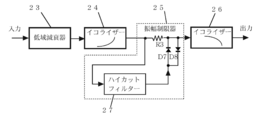
- FIG. 6 is a block diagram (partial circuit diagram) of the sixth embodiment of the present invention.
- the circuit configuration is different from that of FIG. 5, but the results are the same. That is, an equalizer 24 for high frequency emphasis is connected to the output side of the low frequency attenuator 23, an amplitude limiter 25 is connected to the output side of the equalizer 24, and the output from the amplitude limiter 25 is for high frequency attenuation. Is output to the outside via the equalizer 26.
- the amplitude limiter 25 includes forward and reverse diodes D5 and D6 connected in parallel to the subsequent stage of the resistor R3, and a high cut filter 27 connected in parallel to the resistor R3 and the diodes D5 and D6.
- the input side of the high cut filter 27 is connected to the output side of the high frequency emphasis equalizer 24, and the output side of the high cut filter 27 is connected to the reference voltage application side of the diodes D5 and D6.
- the low-frequency attenuator 23 of this embodiment obtains a low-frequency amplitude suppression effect by performing low-frequency attenuation of the input signal.
- the output signal of the low-frequency attenuator 23 is input to the equalizer 24, and the equalizer 24 outputs a signal in which the high frequency is emphasized.
- the amplitude limiter 25 limits the amplitude of the high frequency signal.
- the high cut filter 27 in the amplitude limiter 25 outputs a signal obtained by cutting the high frequency range of the input signal, and this output signal becomes the amplitude limit reference potential of the amplitude limiter 25. That is, the amplitude is limited so that a difference greater than the forward voltage of the diode D5 or D6 is not output compared to the output potential of the high cut filter 27. In this way, the amplitude limiter 25 limits the amplitude only to the high frequency component signal.
- the output signal of the amplitude limiter 25 is output through the equalizer 26. That is, after the high frequency emphasized signal by the equalizer 24 is amplitude limited by the amplitude limiter 25, the high frequency is attenuated by the equalizer 26, so that the output of the equalizer 26 is limited in amplitude to a smaller level as the frequency increases. Signal is output.
- the circuit configuration can be simplified if the low-frequency attenuation characteristic of the low-frequency attenuator 23 is a microphone and the high-frequency attenuation characteristic of the equalizer 26 is an earphone or headphones.
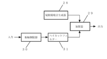
- FIG. 7 is a block diagram of the seventh embodiment of the present invention, which is highly useful in small hearing aids.
- a pseudo environmental sound generator 28 and an adder 29 are added to FIG.
- the simulated environmental sound generator 28 electrically generates an artificial environmental sound signal or outputs an environmental sound signal recorded in another environment.
- the output signals of the simulated environmental sound generator 28 and the high cut filter G31 are added by an adder 29 and output.
- Small hearing aids are usually close to microphones and earphones, and howling is likely to occur. And since howling is likely to occur at frequencies higher than low frequencies, small hearing aids often do not increase the gain at high frequencies, which causes unpleasant sound.
- the environmental sound is added by the pseudo environmental sound generator 28 without increasing the high frequency gain, howling does not easily occur and a comfortable sound without a feeling of blockage or pressure can be obtained. . If the output level of the simulated environmental sound generator 28 is proportional to the ambient environmental noise level, the simulated environmental sound generator 28 can automatically output a signal of an appropriate level according to the environment.
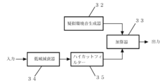
- FIG. 8 is a block diagram of an eighth embodiment of the present invention, which is highly useful in small hearing aids as in FIG.
- the amplitude limiter 30 in FIG. 7 is replaced with a low-frequency attenuator 34.
- the amplitude suppression characteristic is inferior to that of FIG. 7, it is possible to obtain a reproduced sound with less distortion than the configuration of FIG. Even in a normal acoustic device using earphones or headphones, noise that can be heard can be reduced by adding simulated environmental sound to the reproduced sound.
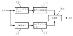
- FIG. 9 is a block diagram of the ninth embodiment of the present invention.
- the intelligibility of the sound to be heard can be set optimally.
- a variable gain amplifier 37 is added to FIG. 2, and the high frequency signal level can be adjusted by the variable gain amplifier 37. Since the sensitivity of the ear changes with the strength of the high frequency sound, changing the level of the high frequency sound can change the way of hearing.
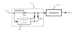
- FIG. 10 is a block diagram of a circuit in which a high frequency component, which is a drawback of the configuration of FIG. 1, is eliminated with a relatively simple configuration.
- two types of amplitude limiters 41 and 43 are used.
- the first amplitude limiter 41 incorporates a high cut filter 42 in the reference voltage application portion, similar to that used in the sixth embodiment of FIG. 6, and limits the amplitude in the high frequency region.
- the second amplitude limiter 42 limits the amplitude in the low frequency region.
- the high-cut filter 2 removes high-frequency distortion components that cause unpleasant noise, but the high-cut filter 2 also removes high-frequency components contained in the original signal. Therefore, a high frequency component is lost in the output signal.
- the output circuit will contain the high frequency signal of the original signal sufficiently, and the high frequency distortion component. Fewer signals are extracted.
- the input signal is input to the amplitude limiter 41, and a low frequency region signal from the high cut filter 42 is used as an operation reference voltage for the diodes D9 and D10, so that high frequency slice type amplitude limitation is performed (this operation is performed). This is the same as the case of the amplitude limiter in FIG. 6).
- the output signal of the amplitude limiter 41 is input to the second amplitude limiter 43, where the bias shift type amplitude limitation of the low frequency signal is performed. At this time, since the level of the high frequency signal input to the amplitude limiter 43 is small, a signal having a high frequency and a small distortion component is obtained in the output circuit of the amplitude limiter 43.
- FIG. 10 the characteristics are slightly sacrificed, but an output signal that is not so different from that in FIG. 4 can be obtained with a simple circuit configuration. That is, when a high frequency signal is subjected to the bias shift type amplitude limitation, a large amount of distortion signals that cause unpleasant reproduced sound are generated. Therefore, in FIG. 10, before the signal is input to the bias shift type amplitude limiter, the high frequency signal is subjected to the slice type amplitude limitation. As a result, the high frequency signal is not subjected to the bias shift type amplitude limitation. The original distortion signal is not produced much. Even with a low frequency signal, a certain amount of high frequency distortion signal is generated due to the bias shift type amplitude limitation, so that the sound quality is deteriorated.
- this circuit is well worth it because its distortion is small. Further, if the high frequency component emphasis and the high frequency component attenuation of the output signal are performed to limit the smaller amplitude as the frequency signal is higher, the high frequency distortion component in the output signal is further reduced.
- the low-cut filter 13 includes an amplitude limiter 14, an inverter 15, an adder 16, an amplitude limiter 17, a high-cut filter 18, a low-cut filter 19, an amplitude limiter 20, an adder 21, a low-frequency attenuator 22, and a high-cut filter 23.
- the band attenuator 24 is an equalizer 25, an amplitude limiter 26, an equalizer 27 is a high cut filter 28, a pseudo environmental sound generator 29 is an adder 30, an amplitude limiter 31 is a high cut filter 32, and a pseudo environmental sound generator 33 is an adder 34.
- the low frequency attenuator 35 is the high cut filter 36 is the low cut.
- the filter 37 is a variable gain amplifier 38, the adder 39, the amplitude limiter 40, the high cut filter 41, the amplitude limiter 42, the high cut filter 43, and the amplitude limiter C are capacitors R1, R2, R3, R4 are resistors D1, D2, D3, D4, D5, D6, D7, D8, D9, D10 are diodes
Landscapes
- Physics & Mathematics (AREA)
- Engineering & Computer Science (AREA)
- Acoustics & Sound (AREA)
- Signal Processing (AREA)
- Health & Medical Sciences (AREA)
- General Health & Medical Sciences (AREA)
- Neurosurgery (AREA)
- Otolaryngology (AREA)
- Circuit For Audible Band Transducer (AREA)
- Tone Control, Compression And Expansion, Limiting Amplitude (AREA)
- Soundproofing, Sound Blocking, And Sound Damping (AREA)
Priority Applications (3)
| Application Number | Priority Date | Filing Date | Title |
|---|---|---|---|
| SG11201510160SA SG11201510160SA (en) | 2013-06-11 | 2014-03-26 | Sound signal amplitude suppressing apparatus |
| EP14811383.0A EP3010146A4 (en) | 2013-06-11 | 2014-03-26 | Audio signal amplitude suppression device |
| US14/956,428 US10097929B2 (en) | 2013-06-11 | 2015-12-02 | Sound signal amplitude suppressing apparatus |
Applications Claiming Priority (4)
| Application Number | Priority Date | Filing Date | Title |
|---|---|---|---|
| JP2013-134290 | 2013-06-11 | ||
| JP2013134290 | 2013-06-11 | ||
| JP2013-189417 | 2013-09-12 | ||
| JP2013189417A JP6151613B2 (ja) | 2013-06-11 | 2013-09-12 | 音声信号振幅抑圧装置 |
Related Child Applications (1)
| Application Number | Title | Priority Date | Filing Date |
|---|---|---|---|
| US14/956,428 Continuation US10097929B2 (en) | 2013-06-11 | 2015-12-02 | Sound signal amplitude suppressing apparatus |
Publications (1)
| Publication Number | Publication Date |
|---|---|
| WO2014199699A1 true WO2014199699A1 (ja) | 2014-12-18 |
Family
ID=52022005
Family Applications (1)
| Application Number | Title | Priority Date | Filing Date |
|---|---|---|---|
| PCT/JP2014/058601 Ceased WO2014199699A1 (ja) | 2013-06-11 | 2014-03-26 | 音声信号振幅抑圧装置 |
Country Status (6)
| Country | Link |
|---|---|
| US (1) | US10097929B2 (enExample) |
| EP (1) | EP3010146A4 (enExample) |
| JP (1) | JP6151613B2 (enExample) |
| SG (1) | SG11201510160SA (enExample) |
| TW (1) | TWI597936B (enExample) |
| WO (1) | WO2014199699A1 (enExample) |
Families Citing this family (8)
| Publication number | Priority date | Publication date | Assignee | Title |
|---|---|---|---|---|
| JP6604728B2 (ja) * | 2015-03-12 | 2019-11-13 | キヤノン株式会社 | 音声処理装置及び音声処理方法 |
| CN106328116B (zh) * | 2015-06-30 | 2020-04-17 | 芋头科技(杭州)有限公司 | 一种机器人室内噪声控制系统 |
| US10791404B1 (en) * | 2018-08-13 | 2020-09-29 | Michael B. Lasky | Assisted hearing aid with synthetic substitution |
| TWI686795B (zh) * | 2018-10-12 | 2020-03-01 | 僑光科技大學 | 用於助聽器之濾波結構以及具有濾波結構之助聽器 |
| JP2023006441A (ja) * | 2021-06-30 | 2023-01-18 | 賢一 大島 | 音声信号の振幅制限回路 |
| JP7722206B2 (ja) * | 2022-01-26 | 2025-08-13 | ヤマハ株式会社 | 音信号処理装置、音響システムおよび音信号処理方法 |
| US12424204B1 (en) | 2022-08-23 | 2025-09-23 | Gn Hearing A/S | Speech recognition hearing device with multiple supportive detection inputs |
| US11968504B1 (en) | 2023-11-27 | 2024-04-23 | The Epstein Hear Us Now Foundation | Hearing-assist systems and methods for audio quality enhancements in performance venues |
Citations (6)
| Publication number | Priority date | Publication date | Assignee | Title |
|---|---|---|---|---|
| US4256975A (en) * | 1977-11-30 | 1981-03-17 | Hitachi, Ltd. | Limiter circuit for removing nose from demodulated signals |
| JP2001320255A (ja) * | 2000-05-08 | 2001-11-16 | Kenichi Oshima | リミッター |
| JP2006197580A (ja) * | 2005-12-28 | 2006-07-27 | Kenichi Oshima | 音声信号振幅制限器 |
| JP2011166652A (ja) | 2010-02-15 | 2011-08-25 | Kenichi Oshima | 振幅抑圧回路 |
| JP4825427B2 (ja) | 2005-01-11 | 2011-11-30 | 賢一 大島 | 振幅制限回路 |
| JP2012151767A (ja) * | 2011-01-20 | 2012-08-09 | Yamaha Corp | オーディオ信号処理装置およびオーディオアンプ |
Family Cites Families (10)
| Publication number | Priority date | Publication date | Assignee | Title |
|---|---|---|---|---|
| JPS51128451U (enExample) * | 1975-04-11 | 1976-10-16 | ||
| GB1541004A (en) * | 1975-11-07 | 1979-02-21 | Nat Res Dev | Hearing aid |
| US4327331A (en) | 1979-11-07 | 1982-04-27 | Pioneer Electronic Corporation | Audio amplifier device |
| US4571548A (en) * | 1983-02-14 | 1986-02-18 | Honeywell Inc. | Floating limiter circuit |
| JPH0510409Y2 (enExample) * | 1987-08-31 | 1993-03-15 | ||
| US5168526A (en) | 1990-10-29 | 1992-12-01 | Akg Acoustics, Inc. | Distortion-cancellation circuit for audio peak limiting |
| US6606388B1 (en) * | 2000-02-17 | 2003-08-12 | Arboretum Systems, Inc. | Method and system for enhancing audio signals |
| JP2003318684A (ja) * | 2002-04-22 | 2003-11-07 | Sony Corp | 振幅制限回路 |
| US7676047B2 (en) | 2002-12-03 | 2010-03-09 | Bose Corporation | Electroacoustical transducing with low frequency augmenting devices |
| JP5392405B2 (ja) * | 2010-05-26 | 2014-01-22 | パナソニック株式会社 | 音量振幅制限装置 |
-
2013
- 2013-09-12 JP JP2013189417A patent/JP6151613B2/ja active Active
-
2014
- 2014-03-26 SG SG11201510160SA patent/SG11201510160SA/en unknown
- 2014-03-26 EP EP14811383.0A patent/EP3010146A4/en not_active Ceased
- 2014-03-26 WO PCT/JP2014/058601 patent/WO2014199699A1/ja not_active Ceased
- 2014-06-06 TW TW103119627A patent/TWI597936B/zh not_active IP Right Cessation
-
2015
- 2015-12-02 US US14/956,428 patent/US10097929B2/en active Active
Patent Citations (7)
| Publication number | Priority date | Publication date | Assignee | Title |
|---|---|---|---|---|
| US4256975A (en) * | 1977-11-30 | 1981-03-17 | Hitachi, Ltd. | Limiter circuit for removing nose from demodulated signals |
| JP2001320255A (ja) * | 2000-05-08 | 2001-11-16 | Kenichi Oshima | リミッター |
| JP4825427B2 (ja) | 2005-01-11 | 2011-11-30 | 賢一 大島 | 振幅制限回路 |
| JP2006197580A (ja) * | 2005-12-28 | 2006-07-27 | Kenichi Oshima | 音声信号振幅制限器 |
| JP4976012B2 (ja) | 2005-12-28 | 2012-07-18 | 賢一 大島 | 音声信号振幅制限器 |
| JP2011166652A (ja) | 2010-02-15 | 2011-08-25 | Kenichi Oshima | 振幅抑圧回路 |
| JP2012151767A (ja) * | 2011-01-20 | 2012-08-09 | Yamaha Corp | オーディオ信号処理装置およびオーディオアンプ |
Non-Patent Citations (1)
| Title |
|---|
| See also references of EP3010146A4 * |
Also Published As
| Publication number | Publication date |
|---|---|
| SG11201510160SA (en) | 2016-01-28 |
| EP3010146A1 (en) | 2016-04-20 |
| US10097929B2 (en) | 2018-10-09 |
| EP3010146A4 (en) | 2017-01-25 |
| JP6151613B2 (ja) | 2017-06-21 |
| JP2015019345A (ja) | 2015-01-29 |
| TWI597936B (zh) | 2017-09-01 |
| US20160088404A1 (en) | 2016-03-24 |
| TW201507351A (zh) | 2015-02-16 |
Similar Documents
| Publication | Publication Date | Title |
|---|---|---|
| JP6151613B2 (ja) | 音声信号振幅抑圧装置 | |
| JP6069830B2 (ja) | 耳孔装着型収音装置、信号処理装置、収音方法 | |
| JP4986182B2 (ja) | 電子機器用音響処理システム、方法及び携帯電話端末 | |
| CN113068091B (zh) | 噪声消除来自触觉振动驱动器的声学噪声的耳机 | |
| KR102943103B1 (ko) | 능동 노이즈 제거 기능을 가진 헤드셋 및 능동 노이즈 제거 방법 | |
| AU4704900A (en) | Hearing aid device incorporating signal processing techniques | |
| CN105284126A (zh) | 包括自适应消噪系统的系数的动态偏置的自适应消噪系统及方法 | |
| CN112954530B (zh) | 一种耳机降噪方法、装置、系统及无线耳机 | |
| EP2337020A1 (en) | A device for and a method of processing an acoustic signal | |
| TW201210356A (en) | Earphone and voice-shielding element therefor | |
| US11688383B2 (en) | Context aware compressor for headphone audio feedback path | |
| US20240323586A1 (en) | Earphone and audio processing method and apparatus therefor, and storage medium | |
| JP2017028718A (ja) | 耳孔装着型収音装置、信号処理装置、収音方法 | |
| JP2008228198A (ja) | 再生音調整装置及び再生音調整方法 | |
| WO2024113810A1 (zh) | 降噪方法、耳机、装置、存储介质及计算机程序产品 | |
| CN115346544A (zh) | 音频信号处理方法、装置、存储介质和程序产品 | |
| US20230006628A1 (en) | Amplitude limiting circuit for sound signal | |
| CN115278424A (zh) | 音频播放方法和音频播放设备 | |
| CN116156385B (zh) | 滤波方法、滤波装置、芯片和耳机 | |
| JP4976012B2 (ja) | 音声信号振幅制限器 | |
| CN115515041A (zh) | 音频播放方法、装置、耳机和存储介质 | |
| JPH05145991A (ja) | 低音域特性補正回路 | |
| WO2024216532A1 (zh) | 滤波方法、滤波装置、芯片和耳机 | |
| JP4825427B2 (ja) | 振幅制限回路 | |
| JP2017175332A (ja) | 耳装着音響再生装置 |
Legal Events
| Date | Code | Title | Description |
|---|---|---|---|
| 121 | Ep: the epo has been informed by wipo that ep was designated in this application |
Ref document number: 14811383 Country of ref document: EP Kind code of ref document: A1 |
|
| NENP | Non-entry into the national phase |
Ref country code: DE |
|
| WWE | Wipo information: entry into national phase |
Ref document number: 2014811383 Country of ref document: EP |