WO2014196585A1 - Substance luminescente, élément organique luminescent et composé - Google Patents
Substance luminescente, élément organique luminescent et composé Download PDFInfo
- Publication number
- WO2014196585A1 WO2014196585A1 PCT/JP2014/064905 JP2014064905W WO2014196585A1 WO 2014196585 A1 WO2014196585 A1 WO 2014196585A1 JP 2014064905 W JP2014064905 W JP 2014064905W WO 2014196585 A1 WO2014196585 A1 WO 2014196585A1
- Authority
- WO
- WIPO (PCT)
- Prior art keywords
- group
- general formula
- substituted
- light emitting
- unsubstituted
- Prior art date
Links
- 0 C*c(c(*C)c(*)c(*)c1*2C)c1-c1c2c(*O)c(*)c(*)c1** Chemical compound C*c(c(*C)c(*)c(*)c1*2C)c1-c1c2c(*O)c(*)c(*)c1** 0.000 description 6
- XZCJVWCMJYNSQO-UHFFFAOYSA-N CC(C)(C)c(cc1)ccc1-c1nnc(-c(cc2)ccc2-c2ccccc2)[o]1 Chemical compound CC(C)(C)c(cc1)ccc1-c1nnc(-c(cc2)ccc2-c2ccccc2)[o]1 XZCJVWCMJYNSQO-UHFFFAOYSA-N 0.000 description 1
- LWKOVLPVKZBGJJ-UHFFFAOYSA-N CC(C1)C=CC=C1C1=C(c2ccccc2)[Si](C)(CI)C(c2ccccc2)=C1c1ccccc1 Chemical compound CC(C1)C=CC=C1C1=C(c2ccccc2)[Si](C)(CI)C(c2ccccc2)=C1c1ccccc1 LWKOVLPVKZBGJJ-UHFFFAOYSA-N 0.000 description 1
Images


Classifications
-
- C—CHEMISTRY; METALLURGY
- C07—ORGANIC CHEMISTRY
- C07D—HETEROCYCLIC COMPOUNDS
- C07D471/00—Heterocyclic compounds containing nitrogen atoms as the only ring hetero atoms in the condensed system, at least one ring being a six-membered ring with one nitrogen atom, not provided for by groups C07D451/00 - C07D463/00
- C07D471/02—Heterocyclic compounds containing nitrogen atoms as the only ring hetero atoms in the condensed system, at least one ring being a six-membered ring with one nitrogen atom, not provided for by groups C07D451/00 - C07D463/00 in which the condensed system contains two hetero rings
- C07D471/04—Ortho-condensed systems
-
- C—CHEMISTRY; METALLURGY
- C07—ORGANIC CHEMISTRY
- C07D—HETEROCYCLIC COMPOUNDS
- C07D403/00—Heterocyclic compounds containing two or more hetero rings, having nitrogen atoms as the only ring hetero atoms, not provided for by group C07D401/00
- C07D403/02—Heterocyclic compounds containing two or more hetero rings, having nitrogen atoms as the only ring hetero atoms, not provided for by group C07D401/00 containing two hetero rings
- C07D403/10—Heterocyclic compounds containing two or more hetero rings, having nitrogen atoms as the only ring hetero atoms, not provided for by group C07D401/00 containing two hetero rings linked by a carbon chain containing aromatic rings
-
- C—CHEMISTRY; METALLURGY
- C07—ORGANIC CHEMISTRY
- C07D—HETEROCYCLIC COMPOUNDS
- C07D413/00—Heterocyclic compounds containing two or more hetero rings, at least one ring having nitrogen and oxygen atoms as the only ring hetero atoms
- C07D413/02—Heterocyclic compounds containing two or more hetero rings, at least one ring having nitrogen and oxygen atoms as the only ring hetero atoms containing two hetero rings
- C07D413/10—Heterocyclic compounds containing two or more hetero rings, at least one ring having nitrogen and oxygen atoms as the only ring hetero atoms containing two hetero rings linked by a carbon chain containing aromatic rings
-
- C—CHEMISTRY; METALLURGY
- C07—ORGANIC CHEMISTRY
- C07D—HETEROCYCLIC COMPOUNDS
- C07D417/00—Heterocyclic compounds containing two or more hetero rings, at least one ring having nitrogen and sulfur atoms as the only ring hetero atoms, not provided for by group C07D415/00
- C07D417/02—Heterocyclic compounds containing two or more hetero rings, at least one ring having nitrogen and sulfur atoms as the only ring hetero atoms, not provided for by group C07D415/00 containing two hetero rings
- C07D417/10—Heterocyclic compounds containing two or more hetero rings, at least one ring having nitrogen and sulfur atoms as the only ring hetero atoms, not provided for by group C07D415/00 containing two hetero rings linked by a carbon chain containing aromatic rings
-
- C—CHEMISTRY; METALLURGY
- C07—ORGANIC CHEMISTRY
- C07D—HETEROCYCLIC COMPOUNDS
- C07D487/00—Heterocyclic compounds containing nitrogen atoms as the only ring hetero atoms in the condensed system, not provided for by groups C07D451/00 - C07D477/00
- C07D487/02—Heterocyclic compounds containing nitrogen atoms as the only ring hetero atoms in the condensed system, not provided for by groups C07D451/00 - C07D477/00 in which the condensed system contains two hetero rings
- C07D487/04—Ortho-condensed systems
-
- C—CHEMISTRY; METALLURGY
- C09—DYES; PAINTS; POLISHES; NATURAL RESINS; ADHESIVES; COMPOSITIONS NOT OTHERWISE PROVIDED FOR; APPLICATIONS OF MATERIALS NOT OTHERWISE PROVIDED FOR
- C09K—MATERIALS FOR MISCELLANEOUS APPLICATIONS, NOT PROVIDED FOR ELSEWHERE
- C09K11/00—Luminescent, e.g. electroluminescent, chemiluminescent materials
- C09K11/06—Luminescent, e.g. electroluminescent, chemiluminescent materials containing organic luminescent materials
-
- H—ELECTRICITY
- H05—ELECTRIC TECHNIQUES NOT OTHERWISE PROVIDED FOR
- H05B—ELECTRIC HEATING; ELECTRIC LIGHT SOURCES NOT OTHERWISE PROVIDED FOR; CIRCUIT ARRANGEMENTS FOR ELECTRIC LIGHT SOURCES, IN GENERAL
- H05B33/00—Electroluminescent light sources
- H05B33/12—Light sources with substantially two-dimensional radiating surfaces
- H05B33/14—Light sources with substantially two-dimensional radiating surfaces characterised by the chemical or physical composition or the arrangement of the electroluminescent material, or by the simultaneous addition of the electroluminescent material in or onto the light source
-
- H—ELECTRICITY
- H10—SEMICONDUCTOR DEVICES; ELECTRIC SOLID-STATE DEVICES NOT OTHERWISE PROVIDED FOR
- H10K—ORGANIC ELECTRIC SOLID-STATE DEVICES
- H10K85/00—Organic materials used in the body or electrodes of devices covered by this subclass
- H10K85/60—Organic compounds having low molecular weight
- H10K85/631—Amine compounds having at least two aryl rest on at least one amine-nitrogen atom, e.g. triphenylamine
- H10K85/636—Amine compounds having at least two aryl rest on at least one amine-nitrogen atom, e.g. triphenylamine comprising heteroaromatic hydrocarbons as substituents on the nitrogen atom
-
- H—ELECTRICITY
- H10—SEMICONDUCTOR DEVICES; ELECTRIC SOLID-STATE DEVICES NOT OTHERWISE PROVIDED FOR
- H10K—ORGANIC ELECTRIC SOLID-STATE DEVICES
- H10K85/00—Organic materials used in the body or electrodes of devices covered by this subclass
- H10K85/60—Organic compounds having low molecular weight
- H10K85/649—Aromatic compounds comprising a hetero atom
- H10K85/657—Polycyclic condensed heteroaromatic hydrocarbons
- H10K85/6572—Polycyclic condensed heteroaromatic hydrocarbons comprising only nitrogen in the heteroaromatic polycondensed ring system, e.g. phenanthroline or carbazole
-
- C—CHEMISTRY; METALLURGY
- C09—DYES; PAINTS; POLISHES; NATURAL RESINS; ADHESIVES; COMPOSITIONS NOT OTHERWISE PROVIDED FOR; APPLICATIONS OF MATERIALS NOT OTHERWISE PROVIDED FOR
- C09K—MATERIALS FOR MISCELLANEOUS APPLICATIONS, NOT PROVIDED FOR ELSEWHERE
- C09K2211/00—Chemical nature of organic luminescent or tenebrescent compounds
- C09K2211/10—Non-macromolecular compounds
- C09K2211/1003—Carbocyclic compounds
- C09K2211/1007—Non-condensed systems
-
- C—CHEMISTRY; METALLURGY
- C09—DYES; PAINTS; POLISHES; NATURAL RESINS; ADHESIVES; COMPOSITIONS NOT OTHERWISE PROVIDED FOR; APPLICATIONS OF MATERIALS NOT OTHERWISE PROVIDED FOR
- C09K—MATERIALS FOR MISCELLANEOUS APPLICATIONS, NOT PROVIDED FOR ELSEWHERE
- C09K2211/00—Chemical nature of organic luminescent or tenebrescent compounds
- C09K2211/10—Non-macromolecular compounds
- C09K2211/1003—Carbocyclic compounds
- C09K2211/1011—Condensed systems
-
- C—CHEMISTRY; METALLURGY
- C09—DYES; PAINTS; POLISHES; NATURAL RESINS; ADHESIVES; COMPOSITIONS NOT OTHERWISE PROVIDED FOR; APPLICATIONS OF MATERIALS NOT OTHERWISE PROVIDED FOR
- C09K—MATERIALS FOR MISCELLANEOUS APPLICATIONS, NOT PROVIDED FOR ELSEWHERE
- C09K2211/00—Chemical nature of organic luminescent or tenebrescent compounds
- C09K2211/10—Non-macromolecular compounds
- C09K2211/1003—Carbocyclic compounds
- C09K2211/1014—Carbocyclic compounds bridged by heteroatoms, e.g. N, P, Si or B
-
- C—CHEMISTRY; METALLURGY
- C09—DYES; PAINTS; POLISHES; NATURAL RESINS; ADHESIVES; COMPOSITIONS NOT OTHERWISE PROVIDED FOR; APPLICATIONS OF MATERIALS NOT OTHERWISE PROVIDED FOR
- C09K—MATERIALS FOR MISCELLANEOUS APPLICATIONS, NOT PROVIDED FOR ELSEWHERE
- C09K2211/00—Chemical nature of organic luminescent or tenebrescent compounds
- C09K2211/10—Non-macromolecular compounds
- C09K2211/1018—Heterocyclic compounds
- C09K2211/1025—Heterocyclic compounds characterised by ligands
- C09K2211/1029—Heterocyclic compounds characterised by ligands containing one nitrogen atom as the heteroatom
-
- C—CHEMISTRY; METALLURGY
- C09—DYES; PAINTS; POLISHES; NATURAL RESINS; ADHESIVES; COMPOSITIONS NOT OTHERWISE PROVIDED FOR; APPLICATIONS OF MATERIALS NOT OTHERWISE PROVIDED FOR
- C09K—MATERIALS FOR MISCELLANEOUS APPLICATIONS, NOT PROVIDED FOR ELSEWHERE
- C09K2211/00—Chemical nature of organic luminescent or tenebrescent compounds
- C09K2211/10—Non-macromolecular compounds
- C09K2211/1018—Heterocyclic compounds
- C09K2211/1025—Heterocyclic compounds characterised by ligands
- C09K2211/1044—Heterocyclic compounds characterised by ligands containing two nitrogen atoms as heteroatoms
- C09K2211/1048—Heterocyclic compounds characterised by ligands containing two nitrogen atoms as heteroatoms with oxygen
-
- H—ELECTRICITY
- H10—SEMICONDUCTOR DEVICES; ELECTRIC SOLID-STATE DEVICES NOT OTHERWISE PROVIDED FOR
- H10K—ORGANIC ELECTRIC SOLID-STATE DEVICES
- H10K50/00—Organic light-emitting devices
- H10K50/10—OLEDs or polymer light-emitting diodes [PLED]
- H10K50/11—OLEDs or polymer light-emitting diodes [PLED] characterised by the electroluminescent [EL] layers
Definitions
- the present invention relates to a compound useful as a light emitting material and an organic light emitting device using the compound.
- organic light emitting devices such as organic electroluminescence devices (organic EL devices)
- organic electroluminescence devices organic electroluminescence devices
- various efforts have been made to increase the light emission efficiency by newly developing and combining electron transport materials, hole transport materials, light emitting materials, and the like constituting the organic electroluminescence element.
- research on organic electroluminescent devices using compounds having a structure in which a phenylene group is bonded to a fused heteroaromatic ring can also be seen.
- Patent Document 1 describes an example in which a compound represented by the following general formula is used as a host material in a light emitting layer existing between a pair of electrodes constituting an organic electroluminescence element.
- R 1 to R 5 in the following general formula are a hydrogen atom, an alkyl group or an aryl group, ⁇ is an arylene group, Ar 1 is an aryl group, A is a diarylaminoaryl group, a substituted carbazol-3-yl Group or a carbazol-9-ylaryl group.
- Patent Document 1 does not describe an example showing the usefulness of the compound represented by the following general formula as a light-emitting material, and Ar 1 and A in the following general formula are bonded to each other. There is also no description of compounds that form cyclic structures.
- Patent Document 2 describes an example in which a compound represented by the following general formula is used as a light emitting material in a light emitting layer existing between a pair of electrodes constituting an organic electroluminescent element.
- R 1 to R 12 in the following general formula are hydrogen atom, halogen atom, lower alkyl group, alkoxy group, acyl group, nitro group, cyano group, amino group, dialkylamino group, diarylamino group, vinyl group, aryl group or It is a heteroaryl group, and Ar 1 to Ar 4 are defined to represent an aryl group or a heteroaryl group.
- the invention described in Patent Document 2 is an invention related to a symmetric compound in which a common diarylphenyl group is substituted at the 2-position and 3-position of the quinoxaline ring, and the utility of other compounds is not described. Absent.
- Patent Document 3 describes an example in which a compound represented by the following general formula is used as a hole transport material in a hole transport layer existing between a pair of electrodes constituting an organic electroluminescence element. ing.
- R 1 , R 2 , R 4 to R 7 are a hydrogen atom, a halogen atom, an alkyl group, an alkoxy group, an aryl group or a heteroaryl group
- R 3 is a hydrogen atom, a halogen atom, an alkyl group
- An alkoxy group, R 8 and R 9 are a halogen atom, an alkyl group, an alkoxy group or an aryl group
- Ar is an aryl group
- a and B are heteroaryl groups having a C ⁇ N bond
- X 1 and X 2 are carbon atoms or nitrogen atoms
- m and n are 0 or 1
- p and q are defined to represent any integer of 0 to 4.
- Patent Document 3 is an invention relating to a compound in which a diarylamino group is bonded to the 2-position of the carbazole ring, and the utility of other compounds is not described. Also, no examples showing the usefulness of the compounds represented by the following general formulas as light emitting materials are described.
- the present inventors have further investigated the usefulness of a compound having a structure in which a phenylene group is bonded to a fused heteroaromatic ring as a luminescent material, and found a compound having excellent luminescent properties.
- the research was repeated aiming at.
- the general formula of the compound useful as a luminescent material was derived, and the earnest examination was advanced for the purpose of generalizing the structure of the organic light emitting element with high luminous efficiency.
- the present inventors have found that a compound having a specific structure has excellent properties as a light emitting material.
- a group of compounds is useful as a delayed fluorescent material, and it has been clarified that an organic light-emitting device having high emission efficiency can be provided at low cost. Based on these findings, the present inventors have provided the following present invention as means for solving the above problems.
- a light emitting material comprising a compound represented by the following general formula (1).
- 1 to 4 of A 1 to A 7 represent N, and the rest each independently represents CR.
- R represents a non-aromatic group.
- Ar 1 to Ar 3 each independently represents a substituted or unsubstituted arylene group.
- Z represents a single bond or a linking group.
- 1 to 4 of A 1 to A 7 represent N, and the rest each independently represents CR.
- R represents a non-aromatic group.
- Ar 1 represents a substituted or unsubstituted arylene group.
- R 11 to R 14 and R 17 to R 20 each independently represents a hydrogen atom or a substituent.
- R 11 and R 12 , R 12 and R 13 , R 13 and R 14 , R 17 and R 18 , R 18 and R 19 , and R 19 and R 20 may be bonded to each other to form a cyclic structure.
- Z 1 represents a single bond or a linking group having 1 or 2 linking chain long atoms.
- R represents a non-aromatic group.
- Ar 1 represents a substituted or unsubstituted arylene group.
- Y represents a substituted or unsubstituted carbazol-9-yl group, a substituted or unsubstituted 10H-phenoxazin-10-yl group, a substituted or unsubstituted 10H-phenothiazin-10-yl group, or a substituted or unsubstituted 10H -Represents a phenazin-5-yl group.
- Y in the general formula (3) is a group represented by any one of the following general formulas (4) to (7).
- R 21 to R 24 , R 27 to R 38 , R 41 to R 48 , R 51 to R 58 , R 61 to R 65 are each independently a hydrogen atom or a substituent. Represents a group.
- R 21 and R 22 , R 22 and R 23 , R 23 and R 24 , R 27 and R 28 , R 28 and R 29 , R 29 and R 30 , R 31 and R 32 , R 32 and R 33 , R 33 And R 34 , R 35 and R 36 , R 36 and R 37 , R 37 and R 38 , R 41 and R 42 , R 42 and R 43 , R 43 and R 44 , R 45 and R 46 , R 46 and R 47 , R 47 and R 48 , R 51 and R 52 , R 52 and R 53 , R 53 and R 54 , R 55 and R 56 , R 56 and R 57 , R 57 and R 58 , R 61 and R 62 , R 62 and R 63 , R 63 and R 64 , R 64 and R 65 , R 54 and R 61 , and R 55 and R 65 may be bonded to each other to form a cyclic structure.
- Y in the general formula (3) is a group represented by the following general formula (8).
- R 21 ′ to R 24 ′ and R 27 ′ to R 30 each independently represents a hydrogen atom or a substituent, and at least one of R 23 ′ and R 28 ′ is a substituent. is there.
- R 21 ' and R 22' , R 22 ' and R 23' , R 23 ' and R 24' , R 27 ' and R 28' , R 28 ' and R 29' , R 29 ' and R 30' are bonded to each other Thus, a ring structure may be formed.
- R 23 ′ and R 28 ′ are a substituted or unsubstituted diarylamino group or a substituted or unsubstituted carbazol-9-yl group [ 5].
- Y in the general formula (3) is a group represented by the general formula (5).
- a delayed phosphor comprising the compound represented by the general formula (1).
- An organic light emitting device comprising the light emitting material according to any one of [1] to [7].
- the organic light-emitting device according to [9] which emits delayed fluorescence.
- the compound represented by the general formula (1) is useful as a light emitting material.
- the compound represented by the general formula (1) includes those that emit delayed fluorescence.
- An organic light emitting device using the compound of the present invention as a light emitting material can realize high luminous efficiency.
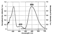
- FIG. 2 is an absorption / emission spectrum of Compound 1 of Example 1.
- 2 is a transient attenuation curve of the organic photoluminescence element of Example 1.
- FIG. 2 is an absorption / emission spectrum of Compound 2 of Example 2.
- 6 is a transient attenuation curve of the organic photoluminescence device of Example 2.
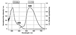
- 2 is an absorption / emission spectrum of Compound 3 of Example 3.
- 6 is a transient attenuation curve of the organic photoluminescence device of Example 3.
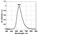
- 6 is an emission spectrum of the organic electroluminescence device of Example 4.
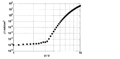
- FIG. 6 is a current density-voltage characteristic of the organic electroluminescence element of Example 4.
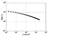
- FIG. 4 is a current density-external quantum efficiency characteristic of the organic electroluminescence element of Example 4.
- FIG. 6 is an emission spectrum of the organic electroluminescence element of Example 5. 6 is a current density-voltage characteristic of the organic electroluminescence element of Example 5.
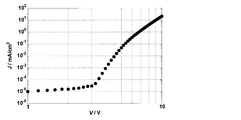
- FIG. 10 is a current density-external quantum efficiency characteristic of the organic electroluminescence element of Example 5.
- a numerical range represented by using “to” means a range including numerical values described before and after “to” as a lower limit value and an upper limit value.
- the isotope species of the hydrogen atom present in the molecule of the compound used in the present invention is not particularly limited. For example, all the hydrogen atoms in the molecule may be 1 H, or a part or all of them are 2 H. (Deuterium D) may be used.
- the luminescent material of the present invention is characterized by comprising a compound represented by the following general formula (1).
- 1 to 4 of A 1 to A 7 represent N, and the rest each independently represents CR.
- the number of N among A 1 to A 7 is more preferably 1 to 3, and even more preferably 2.
- any one of A 1 to A 7 may be N, but preferably one of A 1 to A 3 is N It is.
- 2 to 4 of A 1 to A 7 are N, 2 to 4 N may be present in only one of the two rings, or N is present in both rings. May be.
- a 1 and A 2 When two of A 1 to A 7 are N, for example, A 1 and A 2 , A 1 and A 3 , A 2 and A 3 , A 4 and A 6 , A 4 and A 7 , A 1 And A 4 , A 1 and A 7 , A 2 and A 4 , A 2 and A 7 , A 2 and A 5 , and A 2 and A 6 .
- a preferred combination is a combination in which at least A 1 and A 3 are N.
- a 1 to A 7 other than N each independently represents CR.
- R represents a non-aromatic group. That is, A 1 to A 7 other than N are groups in which a non-aromatic group R is bonded to a carbon atom.
- the non-aromatic ring group here means a group having no aromatic ring or heteroaromatic ring.
- Non-aromatic groups which R can take include, for example, a hydroxy group, a halogen atom, an alkyl group having 1 to 20 carbon atoms, an alkoxy group having 1 to 20 carbon atoms, an alkylthio group having 1 to 20 carbon atoms, and 2 to 10 carbon atoms.
- substituents are a substituted or unsubstituted alkyl group having 1 to 20 carbon atoms and an alkoxy group having 1 to 20 carbon atoms.
- More preferred substituents are a substituted or unsubstituted alkyl group having 1 to 10 carbon atoms and a substituted or unsubstituted alkoxy group having 1 to 10 carbon atoms.
- the alkyl group may be linear, branched or cyclic, and more preferably has 1 to 6 carbon atoms. Specific examples include a methyl group, an ethyl group, a propyl group, a butyl group, and tert-butyl. Group, pentyl group, hexyl group and isopropyl group.
- the alkoxy group may be linear, branched or cyclic, and more preferably has 1 to 6 carbon atoms. Specific examples thereof include methoxy group, ethoxy group, propoxy group, butoxy group, tert-butoxy group. A group, a pentyloxy group, a hexyloxy group, and an isopropyloxy group.
- Ar 1 to Ar 3 in the general formula (1) each independently represent a substituted or unsubstituted arylene group.
- the arylene group that Ar 1 to Ar 3 can take may be a monocyclic arylene group or a condensed ring arylene group. Specific examples include 1,2-phenylene group, 1,3-phenylene group, 1,4-phenylene group, 1,2-naphthylene group, 1,3-naphthylene group, 1,4-naphthylene group, 1,5- Examples thereof include a naphthylene group and a 1,8-naphthylene group.
- Ar 1 is preferably a 1,3-phenylene group, a 1,4-phenylene group, a 1,3-naphthylene group or a 1,4-naphthylene group, more preferably a 1,4-phenylene group or a 1,4-naphthylene group.
- the arylene group that Ar 1 may have may have a substituent.
- substituents include a hydroxy group, a halogen atom, an alkyl group having 1 to 20 carbon atoms, and an alkoxy group having 1 to 20 carbon atoms.
- An alkynyl group etc. are mentioned.
- substituents that can be substituted with a substituent may be further substituted. More preferred substituents are substituted or unsubstituted alkyl groups having 1 to 20 carbon atoms, alkoxy groups having 1 to 20 carbon atoms, substituted or unsubstituted aryl groups having 6 to 40 carbon atoms, and substituted groups having 3 to 40 carbon atoms. Or it is an unsubstituted heteroaryl group.
- substituents are substituted or unsubstituted alkyl groups having 1 to 10 carbon atoms, substituted or unsubstituted alkoxy groups having 1 to 10 carbon atoms, substituted or unsubstituted aryl groups having 6 to 15 carbon atoms, 3 to 12 substituted or unsubstituted heteroaryl groups.
- Ar 2 and Ar 3 are preferably a 1,2-phenylene group or a 1,2-naphthylene group, and more preferably a 1,2-phenylene group.
- the arylene group that Ar 2 and Ar 3 can have may have a substituent.
- substituents include a hydroxy group, a halogen atom, a cyano group, an alkyl group having 1 to 20 carbon atoms, and a carbon number.
- substituents are a halogen atom, a cyano group, a substituted or unsubstituted alkyl group having 1 to 20 carbon atoms, an alkoxy group having 1 to 20 carbon atoms, a substituted or unsubstituted aryl group having 6 to 40 carbon atoms, carbon A substituted or unsubstituted heteroaryl group having 3 to 40 carbon atoms, a substituted or unsubstituted dialkylamino group having 1 to 10 carbon atoms, a substituted or unsubstituted diarylamino group having 12 to 40 carbon atoms, and 12 to 40 carbon atoms A substituted or unsubstituted carbazolyl group; More preferred substituents are a fluorine atom, a chlorine atom, a cyano group, a substituted or unsubstituted alkyl group having 1 to 10
- an unsubstituted dialkylamino group a substituted or unsubstituted diarylamino group having 12 to 40 carbon atoms, a substituted or unsubstituted aryl group having 6 to 15 carbon atoms, and a substituted or unsubstituted heteroaryl group having 3 to 12 carbon atoms It is a group.
- the aryl group described as the above substituent may be a single ring or a condensed ring, and specific examples thereof include a phenyl group and a naphthyl group.
- the heteroaryl group may be a single ring or a condensed ring, and specific examples thereof include a pyridyl group, a pyridazyl group, a pyrimidyl group, a triazyl group, a triazolyl group, and a benzotriazolyl group.
- These heteroaryl groups may be a group bonded through a hetero atom or a group bonded through a carbon atom constituting a heteroaryl ring.
- Z represents a single bond or a linking group.
- Z is is for connecting the Ar 2 and Ar 3, by bonding atoms and Z other than bonded atoms to the nitrogen atom of the formula among the ring-constituting atoms of Ar 2 and Ar 3 (1)
- Z is bonded to the ⁇ -position atom or ⁇ -position atom of Ar 2 and Ar 3 bonded to the nitrogen atom, and the ⁇ -position atom and Z are bonded.
- Z is preferably a single bond or a linking group.
- the number of linking chain long atoms is preferably 1 or 2, and more preferably 1.
- linking group having 1 linking chain length atom examples include —O—, —S—, —C (R 1 ) (R 2 ) —, and —N (R 3 ) —.
- a linking group having two linking chain long atoms —C (R 4 ) (R 5 ) —C (R 6 ) (R 7 ) —, —C (R 8 ) ⁇ C (R 9 ) —
- R 1 to R 9 each independently represents a hydrogen atom or a substituent.
- the specific examples and preferred ranges exemplified as the substituent of the arylene group that Ar 2 and Ar 3 can take can be referred to.
- R 1 and R 2 , R 4 and R 5 , R 6 and R 7 , R 8 and R 9 may be the same or different from each other. Examples of the case where they are the same include a case where both are methyl groups and a case where they are ethyl groups.
- the compound represented by the general formula (1) preferably has a structure represented by the following general formula (2).
- R 11 to R 14 and R 17 to R 20 in the general formula (2) each independently represent a hydrogen atom or a substituent.
- Specific examples and preferred ranges of the substituents that can be taken by R 11 to R 14 and R 17 to R 20 include the specific examples exemplified as the substituent of the arylene group that Ar 2 and Ar 3 can take in the general formula (1) Reference can be made to preferred ranges.
- R 11 and R 12 , R 12 and R 13 , R 13 and R 14 , R 17 and R 18 , R 18 and R 19 , and R 19 and R 20 may be bonded to each other to form a cyclic structure.
- the cyclic structure may be an aromatic ring or an alicyclic ring, may contain a hetero atom, and the cyclic structure may be a condensed ring of two or more rings.
- the hetero atom here is preferably selected from the group consisting of a nitrogen atom, an oxygen atom and a sulfur atom.
- Examples of cyclic structures formed include benzene ring, naphthalene ring, pyridine ring, pyridazine ring, pyrimidine ring, pyrazine ring, pyrrole ring, imidazole ring, pyrazole ring, triazole ring, imidazoline ring, oxazole ring, isoxazole ring, thiazole And a ring, an isothiazole ring, a cyclohexadiene ring, a cyclohexene ring, a cyclopentaene ring, a cycloheptatriene ring, a cycloheptadiene ring, and a cycloheptaene ring.
- the compound represented by the general formula (1) preferably has a structure represented by the following general formula (3).
- Y in the general formula (3) is a substituted or unsubstituted carbazol-9-yl group, a substituted or unsubstituted 10H-phenoxazin-10-yl group, a substituted or unsubstituted 10H-phenothiazin-10-yl group, or It represents a substituted or unsubstituted 10H-phenazin-5-yl group.
- Y in the general formula (3) is preferably a group represented by any of the following general formulas (4) to (7).
- R 21 to R 24 , R 27 to R 38 , R 41 to R 48 , R 51 to R 58 , and R 61 to R 65 are each independently a hydrogen atom or a substituent. Represents.
- R 21 to R 24 , R 27 to R 38 , R 41 to R 48 , R 51 to R 58 , and R 61 to R 65 are each independently any one of the above general formulas (4) to (7). It is also preferable that it is a group represented.
- the number of substituents in the general formulas (4) to (7) is not particularly limited. Moreover, all may be unsubstituted (namely, a hydrogen atom). Further, when there are two or more substituents in each of the general formulas (4) to (7), these substituents may be the same or different. When a substituent is present in the general formulas (4) to (7), the substituent is preferably any one of R 22 to R 24 and R 27 to R 29 in the case of the general formula (4). , R 23 and R 28 are particularly preferred.
- any one of R 32 to R 37 is preferred, and in the general formula (6), R 42 to Any one of R 47 is preferable, and in the case of the general formula (7), any of R 52 , R 53 , R 56 , R 57 and R 62 to R 64 is preferable.
- the cyclic structure may be bonded together to form a cyclic structure. It may
- Y in the general formula (2) is preferably a group represented by the following general formula (8).
- R 21 ′ to R 24 ′ and R 27 ′ to R 30 each independently represent a hydrogen atom or a substituent, and at least one of R 23 ′ and R 28 ′ is a substituent. . That is, R 23 ′ is a substituent, R 28 ′ is a substituent, or both R 23 ′ and R 28 ′ are substituents.
- R 21 ′ to R 24 ′ and R 27 ′ to R 30 when only R 23 ′ is a substituent, only R 28 ′ is a substituent, or R 23 ′ and R 28 The case where only both are substituents can be mentioned.
- R 23 ′ and R 28 ′ When at least one of R 23 ′ and R 28 ′ is a substituent, the emission quantum efficiency tends to be higher than when substituted at other positions. This tendency is particularly remarkable when at least one of R 23 ′ and R 28 ′ is a substituted or unsubstituted diarylamino group or a substituted or unsubstituted carbazol-9-yl group.
- R 21 ′ to R 24 ′ , R 27 ′ to R 30 , the above-mentioned diarylamino group and carbazol-9-yl group are as follows: Ar 2 and Ar in the general formula (1) Specific examples and preferred ranges exemplified as the substituent for the arylene group 3 can be referred to.
- R 21 ′ and R 22 ′ , R 22 ′ and R 23 ′ , R 23 ′ and R 24 ′ , R 27 ′ and R 28 ′ , R 28 ′ and R 29 ′ , R 29 ′ and R 30 ′ may be bonded to each other to form a cyclic structure.
- the corresponding description in the general formula (2) can be referred to.
- the molecular weight of the compound represented by the general formula (1) is, for example, 1500 or less when the organic layer containing the compound represented by the general formula (1) is intended to be formed by vapor deposition. Preferably, it is preferably 1200 or less, more preferably 1000 or less, and even more preferably 800 or less.
- the lower limit of the molecular weight is the molecular weight of the minimum compound represented by the general formula (1).
- the compound represented by the general formula (1) may be formed by a coating method regardless of the molecular weight. If a coating method is used, a film can be formed even with a compound having a relatively large molecular weight.
- a compound containing a plurality of structures represented by the general formula (1) in the molecule as a light emitting material.
- a polymer obtained by previously polymerizing a polymerizable group in the structure represented by the general formula (1) and polymerizing the polymerizable group as a light emitting material.
- a monomer containing a polymerizable functional group in any of R, Ar 1 to Ar 3 , and Z of C—R that can be taken by A 1 to A 7 in the general formula (1) is prepared.
- a polymer having a repeating unit is obtained by polymerizing alone or copolymerized with other monomers, and the polymer is used as a light emitting material.
- dimers and trimers are obtained by reacting compounds having a structure represented by the general formula (1) and used as a luminescent material.
- Examples of the polymer having a repeating unit containing a structure represented by the general formula (1) include a polymer containing a structure represented by the following general formula (9) or (10).
- Q represents a group including the structure represented by General Formula (1)
- L 1 and L 2 represent a linking group.
- the linking group preferably has 0 to 20 carbon atoms, more preferably 1 to 15 carbon atoms, and still more preferably 2 to 10 carbon atoms. And preferably has a structure represented by - linking group -X 11 -L 11.
- X 11 represents an oxygen atom or a sulfur atom, and is preferably an oxygen atom.
- L 11 represents a linking group, preferably a substituted or unsubstituted alkylene group, or a substituted or unsubstituted arylene group, and a substituted or unsubstituted alkylene group having 1 to 10 carbon atoms, or a substituted or unsubstituted group A phenylene group is more preferable.
- R 101 , R 102 , R 103 and R 104 each independently represent a substituent.
- it is a substituted or unsubstituted alkyl group having 1 to 6 carbon atoms, a substituted or unsubstituted alkoxy group having 1 to 6 carbon atoms, or a halogen atom, more preferably an unsubstituted alkyl group having 1 to 3 carbon atoms.
- An unsubstituted alkoxy group having 1 to 3 carbon atoms, a fluorine atom, and a chlorine atom and more preferably an unsubstituted alkyl group having 1 to 3 carbon atoms and an unsubstituted alkoxy group having 1 to 3 carbon atoms.
- the linking group represented by L 1 and L 2 is any one of CR R, Ar 1 to Ar 3 , and Z that can be taken by A 1 to A 7 in the structure of the general formula (1) constituting Q.
- Any one of 61 to R 65 can be bonded to any of R 21 ′ to R 24 ′ and R 27 ′ to R 30 ′ in the structure of the general formula (8).
- repeating unit examples include structures represented by the following formulas (11) to (14).
- a polymer having a repeating unit containing these formulas (11) to (14) is composed of R, Ar 1 to Ar 3 , Z of C—R that A 1 to A 7 in the structure of the general formula (1) can take. It can be synthesized by introducing a hydroxy group into any of them, reacting the following compound as a linker to introduce a polymerizable group, and polymerizing the polymerizable group.
- the polymer containing a structure represented by the general formula (1) in the molecule may be a polymer consisting only of a repeating unit having the structure represented by the general formula (1), or other structures may be used. It may be a polymer containing repeating units.
- the repeating unit having a structure represented by the general formula (1) contained in the polymer may be a single type or two or more types. Examples of the repeating unit not having the structure represented by the general formula (1) include those derived from monomers used in ordinary copolymerization. Examples thereof include a repeating unit derived from a monomer having an ethylenically unsaturated bond such as ethylene and styrene.
- the compound represented by the general formula (2) is a novel compound.
- the compound represented by the general formula (2) can be synthesized by combining known reactions. For example, it can be synthesized by reacting according to the following scheme.
- X represents a halogen atom, and examples thereof include a fluorine atom, a chlorine atom, a bromine atom, and an iodine atom, and a chlorine atom, a bromine atom, and an iodine atom are preferable.
- the above reaction is an application of a known reaction, and known reaction conditions can be appropriately selected and used. The details of the above reaction can be referred to the synthesis examples described below.
- the compound represented by the general formula (2) can also be synthesized by combining other known synthesis reactions.
- the compound represented by the general formula (1) of the present invention is useful as a light emitting material of an organic light emitting device. For this reason, the compound represented by General formula (1) of this invention can be effectively used as a luminescent material for the light emitting layer of an organic light emitting element.
- the compound represented by the general formula (1) includes a delayed fluorescent material (delayed phosphor) that emits delayed fluorescence. That is, the present invention relates to a delayed phosphor having a structure represented by the general formula (1), an invention using a compound represented by the general formula (1) as a delayed phosphor, and a general formula (1).
- An invention of a method for emitting delayed fluorescence using the represented compound is also provided.
- An organic light emitting device using such a compound as a light emitting material emits delayed fluorescence and has a feature of high luminous efficiency. The principle will be described below by taking an organic electroluminescence element as an example.
- the organic electroluminescence element carriers are injected into the light emitting material from both positive and negative electrodes to generate an excited light emitting material and emit light.
- 25% of the generated excitons are excited to the excited singlet state, and the remaining 75% are excited to the excited triplet state. Therefore, the use efficiency of energy is higher when phosphorescence, which is light emission from an excited triplet state, is used.
- the excited triplet state has a long lifetime, energy saturation occurs due to saturation of the excited state and interaction with excitons in the excited triplet state, and in general, the quantum yield of phosphorescence is often not high.
- delayed fluorescent materials after energy transition to an excited triplet state due to intersystem crossing, etc., are then crossed back to an excited singlet state due to triplet-triplet annihilation or absorption of thermal energy, and emit fluorescence.
- a thermally activated delayed fluorescent material by absorption of thermal energy is particularly useful.
- excitons in the excited singlet state emit fluorescence as usual.
- excitons in the excited triplet state absorb heat generated by the device and cross between the excited singlets to emit fluorescence.
- the light is emitted from the excited singlet, the light is emitted at the same wavelength as the fluorescence, but the light lifetime (luminescence lifetime) generated by the reverse intersystem crossing from the excited triplet state to the excited singlet state is normal. Since the fluorescence becomes longer than the fluorescence and phosphorescence, it is observed as fluorescence delayed from these. This can be defined as delayed fluorescence. If such a heat-activated exciton transfer mechanism is used, the ratio of the compound in an excited singlet state, which normally generated only 25%, is increased to 25% or more by absorbing thermal energy after carrier injection. It can be raised.
- the heat of the device will sufficiently cause intersystem crossing from the excited triplet state to the excited singlet state and emit delayed fluorescence. Efficiency can be improved dramatically.
- the compound represented by the general formula (1) of the present invention as a light-emitting material of a light-emitting layer, excellent organic light-emitting devices such as an organic photoluminescence device (organic PL device) and an organic electroluminescence device (organic EL device) Can be provided.
- the compound represented by the general formula (1) of the present invention may have a function of assisting light emission of another light emitting material included in the light emitting layer as a so-called assist dopant. That is, the compound represented by the general formula (1) of the present invention contained in the light emitting layer includes the lowest excitation singlet energy level of the host material contained in the light emitting layer and the lowest excitation of other light emitting materials contained in the light emitting layer.
- the organic photoluminescence element has a structure in which at least a light emitting layer is formed on a substrate.
- the organic electroluminescence element has a structure in which an organic layer is formed at least between an anode, a cathode, and an anode and a cathode.
- the organic layer includes at least a light emitting layer, and may consist of only the light emitting layer, or may have one or more organic layers in addition to the light emitting layer. Examples of such other organic layers include a hole transport layer, a hole injection layer, an electron blocking layer, a hole blocking layer, an electron injection layer, an electron transport layer, and an exciton blocking layer.
- the hole transport layer may be a hole injection / transport layer having a hole injection function
- the electron transport layer may be an electron injection / transport layer having an electron injection function.
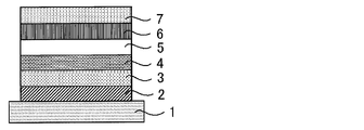
- FIG. 1 A specific example of the structure of an organic electroluminescence element is shown in FIG.
- 1 is a substrate
- 2 is an anode
- 3 is a hole injection layer
- 4 is a hole transport layer
- 5 is a light emitting layer
- 6 is an electron transport layer
- 7 is a cathode.
- each member and each layer of an organic electroluminescent element are demonstrated.
- substrate and a light emitting layer corresponds also to the board
- the organic electroluminescence device of the present invention is preferably supported on a substrate.
- the substrate is not particularly limited and may be any substrate conventionally used for organic electroluminescence elements.
- a substrate made of glass, transparent plastic, quartz, silicon, or the like can be used.
- an electrode material made of a metal, an alloy, an electrically conductive compound, or a mixture thereof having a high work function (4 eV or more) is preferably used.
- electrode materials include metals such as Au, and conductive transparent materials such as CuI, indium tin oxide (ITO), SnO 2 , and ZnO.
- conductive transparent materials such as CuI, indium tin oxide (ITO), SnO 2 , and ZnO.
- an amorphous material such as IDIXO (In 2 O 3 —ZnO) that can form a transparent conductive film may be used.
- a thin film may be formed by vapor deposition or sputtering of these electrode materials, and a pattern of a desired shape may be formed by photolithography, or when pattern accuracy is not so high (about 100 ⁇ m or more) ), A pattern may be formed through a mask having a desired shape at the time of vapor deposition or sputtering of the electrode material.
- wet film-forming methods such as a printing system and a coating system, can also be used.
- the transmittance be greater than 10%, and the sheet resistance as the anode is preferably several hundred ⁇ / ⁇ or less.
- the film thickness depends on the material, it is usually selected in the range of 10 to 1000 nm, preferably 10 to 200 nm.
- cathode a material having a low work function (4 eV or less) metal (referred to as an electron injecting metal), an alloy, an electrically conductive compound, and a mixture thereof as an electrode material is used.
- electrode materials include sodium, sodium-potassium alloy, magnesium, lithium, magnesium / copper mixture, magnesium / silver mixture, magnesium / aluminum mixture, magnesium / indium mixture, aluminum / aluminum oxide (Al 2 O 3 ) Mixtures, indium, lithium / aluminum mixtures, rare earth metals and the like.
- a mixture of an electron injecting metal and a second metal which is a stable metal having a larger work function value than this for example, a magnesium / silver mixture
- Suitable are a magnesium / aluminum mixture, a magnesium / indium mixture, an aluminum / aluminum oxide (Al 2 O 3 ) mixture, a lithium / aluminum mixture, aluminum and the like.
- the cathode can be produced by forming a thin film of these electrode materials by a method such as vapor deposition or sputtering.
- the sheet resistance as the cathode is preferably several hundred ⁇ / ⁇ or less, and the film thickness is usually selected in the range of 10 nm to 5 ⁇ m, preferably 50 to 200 nm.
- the emission luminance is advantageously improved.
- a transparent or semi-transparent cathode can be produced. By applying this, an element in which both the anode and the cathode are transparent is used. Can be produced.
- the light emitting layer is a layer that emits light after excitons are generated by recombination of holes and electrons injected from each of the anode and the cathode, and the light emitting material may be used alone for the light emitting layer. , Preferably including a luminescent material and a host material.
- a luminescent material the 1 type (s) or 2 or more types chosen from the compound group of this invention represented by General formula (1) can be used.
- a host material in addition to the light emitting material in the light emitting layer.
- the host material an organic compound having at least one of excited singlet energy and excited triplet energy higher than that of the light emitting material of the present invention can be used.
- singlet excitons and triplet excitons generated in the light emitting material of the present invention can be confined in the molecules of the light emitting material of the present invention, and the light emission efficiency can be sufficiently extracted.
- high luminous efficiency can be obtained, so that host materials that can achieve high luminous efficiency are particularly limited. And can be used in the present invention.
- the organic light emitting device or organic electroluminescent device of the present invention light emission is generated from the light emitting material of the present invention contained in the light emitting layer. This emission includes both fluorescence and delayed fluorescence. However, light emission from the host material may be partly or partly emitted.
- the amount of the compound of the present invention, which is a light emitting material is preferably 0.1% by weight or more, more preferably 1% by weight or more, and 50% or more. It is preferably no greater than wt%, more preferably no greater than 20 wt%, and even more preferably no greater than 10 wt%.
- the host material in the light-emitting layer is preferably an organic compound that has a hole transporting ability and an electron transporting ability, prevents the emission of longer wavelengths, and has a high glass transition temperature.
- the injection layer is a layer provided between the electrode and the organic layer for lowering the driving voltage and improving the luminance of light emission.
- the injection layer can be provided as necessary.
- the blocking layer is a layer that can prevent diffusion of charges (electrons or holes) and / or excitons existing in the light emitting layer to the outside of the light emitting layer.
- the electron blocking layer can be disposed between the light emitting layer and the hole transport layer and blocks electrons from passing through the light emitting layer toward the hole transport layer.
- a hole blocking layer can be disposed between the light emitting layer and the electron transporting layer to prevent holes from passing through the light emitting layer toward the electron transporting layer.
- the blocking layer can also be used to block excitons from diffusing outside the light emitting layer. That is, each of the electron blocking layer and the hole blocking layer can also function as an exciton blocking layer.
- the term “electron blocking layer” or “exciton blocking layer” as used herein is used in the sense of including a layer having the functions of an electron blocking layer and an exciton blocking layer in one layer.
- the hole blocking layer has a function of an electron transport layer in a broad sense.
- the hole blocking layer has a role of blocking holes from reaching the electron transport layer while transporting electrons, thereby improving the recombination probability of electrons and holes in the light emitting layer.
- the material for the hole blocking layer the material for the electron transport layer described later can be used as necessary.
- the electron blocking layer has a function of transporting holes in a broad sense.
- the electron blocking layer has a role to block electrons from reaching the hole transport layer while transporting holes, thereby improving the probability of recombination of electrons and holes in the light emitting layer. .
- the exciton blocking layer is a layer for preventing excitons generated by recombination of holes and electrons in the light emitting layer from diffusing into the charge transport layer. It becomes possible to efficiently confine in the light emitting layer, and the light emission efficiency of the device can be improved.
- the exciton blocking layer can be inserted on either the anode side or the cathode side adjacent to the light emitting layer, or both can be inserted simultaneously.
- the layer when the exciton blocking layer is provided on the anode side, the layer can be inserted adjacent to the light emitting layer between the hole transport layer and the light emitting layer, and when inserted on the cathode side, the light emitting layer and the cathode Between the luminescent layer and the light-emitting layer.
- a hole injection layer, an electron blocking layer, or the like can be provided between the anode and the exciton blocking layer adjacent to the anode side of the light emitting layer, and the excitation adjacent to the cathode and the cathode side of the light emitting layer can be provided.
- an electron injection layer, an electron transport layer, a hole blocking layer, and the like can be provided.
- the blocking layer is disposed, at least one of the excited singlet energy and the excited triplet energy of the material used as the blocking layer is preferably higher than the excited singlet energy and the excited triplet energy of the light emitting material.
- the hole transport layer is made of a hole transport material having a function of transporting holes, and the hole transport layer can be provided as a single layer or a plurality of layers.
- the hole transport material has any one of hole injection or transport and electron barrier properties, and may be either organic or inorganic.
- hole transport materials that can be used include, for example, triazole derivatives, oxadiazole derivatives, imidazole derivatives, carbazole derivatives, indolocarbazole derivatives, polyarylalkane derivatives, pyrazoline derivatives and pyrazolone derivatives, phenylenediamine derivatives, arylamine derivatives, Examples include amino-substituted chalcone derivatives, oxazole derivatives, styrylanthracene derivatives, fluorenone derivatives, hydrazone derivatives, stilbene derivatives, silazane derivatives, aniline copolymers, and conductive polymer oligomers, particularly thiophene oligomers.
- An aromatic tertiary amine compound and an styrylamine compound are preferably used, and an aromatic tertiary amine compound is more preferably used.
- the electron transport layer is made of a material having a function of transporting electrons, and the electron transport layer can be provided as a single layer or a plurality of layers.
- the electron transport material (which may also serve as a hole blocking material) may have a function of transmitting electrons injected from the cathode to the light emitting layer.
- Examples of the electron transport layer that can be used include nitro-substituted fluorene derivatives, diphenylquinone derivatives, thiopyran dioxide oxide derivatives, carbodiimides, fluorenylidenemethane derivatives, anthraquinodimethane and anthrone derivatives, oxadiazole derivatives, and the like.
- a thiadiazole derivative in which the oxygen atom of the oxadiazole ring is substituted with a sulfur atom, and a quinoxaline derivative having a quinoxaline ring known as an electron withdrawing group can also be used as an electron transport material.
- a polymer material in which these materials are introduced into a polymer chain or these materials are used as a polymer main chain can also be used.
- the compound represented by the general formula (1) may be used not only for the light emitting layer but also for layers other than the light emitting layer.
- the compound represented by General formula (1) used for a light emitting layer and the compound represented by General formula (1) used for layers other than a light emitting layer may be same or different.
- the compound represented by the general formula (1) may be used for the injection layer, blocking layer, hole blocking layer, electron blocking layer, exciton blocking layer, hole transporting layer, electron transporting layer, and the like. .
- the method for forming these layers is not particularly limited, and the layer may be formed by either a dry process or a wet process.
- the preferable material which can be used for an organic electroluminescent element is illustrated concretely.
- the material that can be used in the present invention is not limited to the following exemplary compounds. Moreover, even if it is a compound illustrated as a material which has a specific function, it can also be diverted as a material which has another function.
- R and R 2 to R 7 each independently represent a hydrogen atom or a substituent.
- n represents an integer of 3 to 5.
- the organic electroluminescence device produced by the above-described method emits light by applying an electric field between the anode and the cathode of the obtained device. At this time, if the light is emitted by excited singlet energy, light having a wavelength corresponding to the energy level is confirmed as fluorescence emission and delayed fluorescence emission. In addition, in the case of light emission by excited triplet energy, a wavelength corresponding to the energy level is confirmed as phosphorescence. Since normal fluorescence has a shorter fluorescence lifetime than delayed fluorescence, the emission lifetime can be distinguished from fluorescence and delayed fluorescence.
- the excited triplet energy is unstable and is converted into heat and the like, and the lifetime is short and it is immediately deactivated.
- the excited triplet energy of a normal organic compound it can be measured by observing light emission under extremely low temperature conditions.
- the organic electroluminescence element of the present invention can be applied to any of a single element, an element having a structure arranged in an array, and a structure in which an anode and a cathode are arranged in an XY matrix.
- an organic light emitting device with greatly improved light emission efficiency can be obtained by containing the compound represented by the general formula (1) in the light emitting layer.
- the organic light emitting device such as the organic electroluminescence device of the present invention can be further applied to various uses. For example, it is possible to produce an organic electroluminescence display device using the organic electroluminescence element of the present invention. For details, see “Organic EL Display” (Ohm Co., Ltd.) ) Can be referred to.
- the organic electroluminescence device of the present invention can be applied to organic electroluminescence illumination and backlights that are in great demand.
- source meter manufactured by Keithley: 2400 series
- semiconductor parameter analyzer manufactured by Agilent Technologies: E5273A
- optical power meter measuring device manufactured by Newport: 1930C
- optical spectrometer Ocean Optics, USB2000
- spectroradiometer Topcon, SR-3
- streak camera Haamamatsu Photonics C4334
- Example 1 Production and Evaluation of Organic Photoluminescence Device Using Compound 1
- a toluene solution (concentration 10 ⁇ 5 mol / L) of Compound 1 was prepared in a glove box under an Ar atmosphere.
- the results of measuring the absorption spectrum of the prepared toluene solution and the emission spectrum by 410 nm excitation light are shown in FIG.
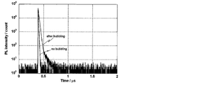
- FIG. 3 shows a transient decay curve in which delayed fluorescence was observed at a peak wavelength of 559 nm for a toluene solution bubbled with nitrogen.
- This transient decay curve shows the result of measuring the luminescence lifetime obtained by measuring the process in which the emission intensity is deactivated by applying excitation light to the compound.
- Example 2 Production and Evaluation of Organic Photoluminescence Element Using Compound 2
- a toluene solution of Compound 2 (concentration 10 ⁇ 5 mol / L) was prepared in a glove box under an Ar atmosphere.
- FIG. 4 shows the results of measuring the absorption spectrum of the prepared toluene solution and the emission spectrum by the excitation light at 382 nm.
- FIG. 5 shows a transient decay curve in which delayed fluorescence was observed at a peak wavelength of 533 nm for the toluene solution before and after nitrogen bubbling.
- the photoluminescence quantum efficiency was 20.6% with a toluene solution without bubbling and 53.5% with a toluene solution bubbling with nitrogen.
- Example 3 Production and Evaluation of Organic Photoluminescence Device Using Compound 3
- a toluene solution of Compound 3 (concentration 10 ⁇ 5 mol / L) was prepared in a glove box under an Ar atmosphere.
- FIG. 6 shows the results of measuring the absorption spectrum of the prepared toluene solution and the emission spectrum by 400 nm excitation light.
- FIG. 7 shows a transient decay curve in which delayed fluorescence was observed at a peak wavelength of 548 nm for the toluene solution before and after nitrogen bubbling.
- the photoluminescence quantum efficiency was 23.2% with a toluene solution without bubbling and 55.4% with a toluene solution bubbling with nitrogen.
- Example 4 Production and evaluation of organic electroluminescence element using compound 1 Each thin film was formed by vacuum deposition on a glass substrate on which an anode made of indium tin oxide (ITO) having a thickness of 100 nm was formed. And a degree of vacuum of 5.0 ⁇ 10 ⁇ 4 Pa. First, ⁇ -NPD was formed to a thickness of 30 nm on ITO, and then mCP was formed to a thickness of 10 nm. Next, Compound 1 and DPEPO were co-evaporated from different vapor deposition sources to form a layer having a thickness of 15 nm as a light emitting layer. At this time, the concentration of Compound 1 was 6.0% by weight.
- ITO indium tin oxide
- TPBi is formed to a thickness of 65 nm
- further lithium fluoride (LiF) is vacuum-deposited to a thickness of 0.5 nm
- aluminum (Al) is evaporated to a thickness of 100 nm to form a cathode.
- a luminescence element was obtained.
- a semiconductor parameter analyzer manufactured by Agilent Technologies: E5273A
- an optical power meter measurement device manufactured by Newport: 1930C
- an optical spectrometer manufactured by Ocean Optics: USB2000
- emission of 563 nm was observed as shown in FIG.
- the current density-voltage characteristic is shown in FIG. 9, and the current density-external quantum efficiency characteristic is shown in FIG.
- the organic electroluminescence device using Compound 1 as the light emitting material achieved an external quantum efficiency of 8.6%.
- Example 5 Production and evaluation of organic electroluminescence device using compound 3 Each thin film was formed by vacuum deposition on a glass substrate on which an anode made of indium tin oxide (ITO) having a thickness of 100 nm was formed. And a degree of vacuum of 5.0 ⁇ 10 ⁇ 4 Pa. First, ⁇ -NPD was formed to a thickness of 30 nm on ITO, and then mCP was formed to a thickness of 10 nm. Next, Compound 3 and DPEPO were co-evaporated from different vapor deposition sources to form a layer having a thickness of 15 nm as a light emitting layer. At this time, the concentration of Compound 3 was 6.0% by weight.
- ITO indium tin oxide
- TPBi is formed to a thickness of 65 nm
- further lithium fluoride (LiF) is vacuum-deposited to a thickness of 0.5 nm
- aluminum (Al) is evaporated to a thickness of 100 nm to form a cathode.
- a luminescence element was obtained.
- a semiconductor parameter analyzer manufactured by Agilent Technologies: E5273A
- an optical power meter measurement device manufactured by Newport: 1930C
- an optical spectrometer manufactured by Ocean Optics: USB2000
- the organic electroluminescence device using Compound 1 as the light emitting material achieved an external quantum efficiency of 12.8%. Assuming that an ideal organic electroluminescence device balanced using a fluorescent material having a light emission quantum efficiency of 100% is prototyped, if the light extraction efficiency is 20 to 30%, the external quantum efficiency of fluorescence emission is 5%. 7.5%. This value is generally regarded as a theoretical limit value of the external quantum efficiency of an organic electroluminescence device using a fluorescent material. As is clear from FIG. 13, the organic electroluminescence device of the present invention using Compound 1 is extremely excellent in that high external quantum efficiency exceeding the theoretical limit value is realized.
- the compound of the present invention is useful as a luminescent material. For this reason, the compound of this invention is effectively used as a luminescent material for organic light emitting elements, such as an organic electroluminescent element. Since the compounds of the present invention include those that emit delayed fluorescence, it is also possible to provide an organic light-emitting device with high luminous efficiency. For this reason, this invention has high industrial applicability.
Landscapes
- Chemical & Material Sciences (AREA)
- Organic Chemistry (AREA)
- Engineering & Computer Science (AREA)
- Materials Engineering (AREA)
- Physics & Mathematics (AREA)
- Spectroscopy & Molecular Physics (AREA)
- Electroluminescent Light Sources (AREA)
- Plural Heterocyclic Compounds (AREA)
Abstract
L'invention concerne un composé représenté par la formule générale suivante, qui est utile comme substance luminescente. Dans la formule, un à quatre symboles parmi A1 à A7 représentent N, et les autres représentent C-R (R représente un groupe non aromatique) ; Ar1 à Ar3 représentent un groupe arylène ; et Z représente une simple liaison ou un groupe de liaison.
Priority Applications (1)
| Application Number | Priority Date | Filing Date | Title |
|---|---|---|---|
| JP2015521476A JP6367189B2 (ja) | 2013-06-05 | 2014-06-05 | 発光材料、有機発光素子および化合物 |
Applications Claiming Priority (2)
| Application Number | Priority Date | Filing Date | Title |
|---|---|---|---|
| JP2013119225 | 2013-06-05 | ||
| JP2013-119225 | 2013-06-05 |
Publications (1)
| Publication Number | Publication Date |
|---|---|
| WO2014196585A1 true WO2014196585A1 (fr) | 2014-12-11 |
Family
ID=52008217
Family Applications (1)
| Application Number | Title | Priority Date | Filing Date |
|---|---|---|---|
| PCT/JP2014/064905 WO2014196585A1 (fr) | 2013-06-05 | 2014-06-05 | Substance luminescente, élément organique luminescent et composé |
Country Status (3)
| Country | Link |
|---|---|
| JP (1) | JP6367189B2 (fr) |
| TW (1) | TW201504230A (fr) |
| WO (1) | WO2014196585A1 (fr) |
Cited By (20)
| Publication number | Priority date | Publication date | Assignee | Title |
|---|---|---|---|---|
| US9741941B2 (en) | 2014-04-29 | 2017-08-22 | Universal Display Corporation | Organic electroluminescent materials and devices |
| KR20170134841A (ko) | 2016-05-26 | 2017-12-07 | 삼성디스플레이 주식회사 | 함질소 화합물 및 이를 포함하는 유기 전계 발광 소자 |
| WO2020076796A1 (fr) | 2018-10-09 | 2020-04-16 | Kyulux, Inc. | Nouvelle composition de matière destinée à être utilisée dans des diodes électroluminescentes organiques |
| WO2021157593A1 (fr) | 2020-02-04 | 2021-08-12 | 株式会社Kyulux | Composition, film, élément électroluminescent organique, procédé de fourniture de composition électroluminescente, et programme |
| US11101440B2 (en) | 2015-07-01 | 2021-08-24 | Kyushu University, National University Corporation | Organic electroluminescent device |
| WO2021235549A1 (fr) | 2020-05-22 | 2021-11-25 | 株式会社Kyulux | Composé, matériau électroluminescent et élément électroluminescent |
| WO2022025248A1 (fr) | 2020-07-31 | 2022-02-03 | 株式会社Kyulux | Composé, matériau luminescent, et élément luminescent |
| US11335872B2 (en) | 2016-09-06 | 2022-05-17 | Kyulux, Inc. | Organic light-emitting device |
| WO2022168956A1 (fr) | 2021-02-04 | 2022-08-11 | 株式会社Kyulux | Composé, matériau électroluminescent et élément électroluminescent organique |
| US11476435B2 (en) | 2017-08-24 | 2022-10-18 | Kyushu University, National University Corporation | Film and organic light-emitting device containing perovskite-type compound and organic light-emitting material |
| US11482679B2 (en) | 2017-05-23 | 2022-10-25 | Kyushu University, National University Corporation | Compound, light-emitting lifetime lengthening agent, use of n-type compound, film and light-emitting device |
| WO2022244503A1 (fr) | 2021-05-20 | 2022-11-24 | 株式会社Kyulux | Elément électroluminescent organique |
| WO2022270354A1 (fr) | 2021-06-23 | 2022-12-29 | 株式会社Kyulux | Composé, matériau électroluminescent et élément électroluminescent organique |
| WO2022270602A1 (fr) | 2021-06-23 | 2022-12-29 | 株式会社Kyulux | Élément électroluminescent organique et film |
| WO2023282224A1 (fr) | 2021-07-06 | 2023-01-12 | 株式会社Kyulux | Élément émetteur de lumière organique et son procédé de conception |
| WO2023053835A1 (fr) | 2021-09-28 | 2023-04-06 | 株式会社Kyulux | Composé, composition, matériau hôte, matériau barrière aux électrons et élément électroluminescent organique |
| WO2023090288A1 (fr) | 2021-11-19 | 2023-05-25 | 株式会社Kyulux | Composé, matériau électroluminescent et élément électroluminescent |
| WO2023140130A1 (fr) | 2022-01-19 | 2023-07-27 | 株式会社Kyulux | Composé, matériau électroluminescent et dispositif électroluminescent organique |
| US11930654B2 (en) | 2017-07-06 | 2024-03-12 | Kyulux, Inc. | Organic light-emitting element |
| US12048175B2 (en) | 2015-12-28 | 2024-07-23 | Kyushu University, National University Corporation | Organic electroluminescent device |
Citations (4)
| Publication number | Priority date | Publication date | Assignee | Title |
|---|---|---|---|---|
| JP2006199677A (ja) * | 2004-12-24 | 2006-08-03 | Sogo Pharmaceutical Co Ltd | キノリン誘導体及びこれを含有する有機el素子 |
| JP2007262134A (ja) * | 2006-03-27 | 2007-10-11 | Showa Denko Kk | 高分子発光材料、有機エレクトロルミネッセンス素子および表示装置 |
| JP2007284434A (ja) * | 2006-03-21 | 2007-11-01 | Semiconductor Energy Lab Co Ltd | キノキサリン誘導体、およびキノキサリン誘導体を用いた発光素子、発光装置、電子機器 |
| JP2010059144A (ja) * | 2008-06-25 | 2010-03-18 | Gracel Display Inc | 新規な有機電界発光化合物及びこれを使用する有機電界発光素子 |
Family Cites Families (4)
| Publication number | Priority date | Publication date | Assignee | Title |
|---|---|---|---|---|
| KR20110008723A (ko) * | 2009-07-21 | 2011-01-27 | 다우어드밴스드디스플레이머티리얼 유한회사 | 신규한 유기 발광 화합물 및 이를 포함하는 유기 전계 발광 소자 |
| KR20110102055A (ko) * | 2010-03-10 | 2011-09-16 | 제일모직주식회사 | 유기광전소자용 화합물 및 이를 포함하는 유기광전소자 |
| WO2012077902A2 (fr) * | 2010-12-08 | 2012-06-14 | 제일모직 주식회사 | Composé pour dispositif optoélectronique organique, diode électroluminescente organique comprenant le composé, et dispositif d'affichage comprenant la diode électroluminescente organique |
| KR101809899B1 (ko) * | 2011-02-14 | 2017-12-21 | 에스에프씨 주식회사 | 피리딘 유도체 화합물 및 이를 포함하는 유기전계발광소자 |
-
2014
- 2014-06-05 WO PCT/JP2014/064905 patent/WO2014196585A1/fr active Application Filing
- 2014-06-05 JP JP2015521476A patent/JP6367189B2/ja active Active
- 2014-06-05 TW TW103119610A patent/TW201504230A/zh unknown
Patent Citations (4)
| Publication number | Priority date | Publication date | Assignee | Title |
|---|---|---|---|---|
| JP2006199677A (ja) * | 2004-12-24 | 2006-08-03 | Sogo Pharmaceutical Co Ltd | キノリン誘導体及びこれを含有する有機el素子 |
| JP2007284434A (ja) * | 2006-03-21 | 2007-11-01 | Semiconductor Energy Lab Co Ltd | キノキサリン誘導体、およびキノキサリン誘導体を用いた発光素子、発光装置、電子機器 |
| JP2007262134A (ja) * | 2006-03-27 | 2007-10-11 | Showa Denko Kk | 高分子発光材料、有機エレクトロルミネッセンス素子および表示装置 |
| JP2010059144A (ja) * | 2008-06-25 | 2010-03-18 | Gracel Display Inc | 新規な有機電界発光化合物及びこれを使用する有機電界発光素子 |
Non-Patent Citations (1)
| Title |
|---|
| "Novel Electron-Transporting Carbazolylphenylquinolines for Phosphorescent Organic Light-Emitting Diodes", JAPANESE JOURNAL OF APPLIED PHYSICS, vol. 45, no. 12, 2006, pages 9228 - 9230 * |
Cited By (22)
| Publication number | Priority date | Publication date | Assignee | Title |
|---|---|---|---|---|
| US9741941B2 (en) | 2014-04-29 | 2017-08-22 | Universal Display Corporation | Organic electroluminescent materials and devices |
| US11101440B2 (en) | 2015-07-01 | 2021-08-24 | Kyushu University, National University Corporation | Organic electroluminescent device |
| US12048175B2 (en) | 2015-12-28 | 2024-07-23 | Kyushu University, National University Corporation | Organic electroluminescent device |
| US10686139B2 (en) | 2016-05-26 | 2020-06-16 | Samsung Display Co., Ltd. | Nitrogen-containing compound and organic electroluminescence device including the same |
| KR20170134841A (ko) | 2016-05-26 | 2017-12-07 | 삼성디스플레이 주식회사 | 함질소 화합물 및 이를 포함하는 유기 전계 발광 소자 |
| US11335872B2 (en) | 2016-09-06 | 2022-05-17 | Kyulux, Inc. | Organic light-emitting device |
| US11482679B2 (en) | 2017-05-23 | 2022-10-25 | Kyushu University, National University Corporation | Compound, light-emitting lifetime lengthening agent, use of n-type compound, film and light-emitting device |
| US11930654B2 (en) | 2017-07-06 | 2024-03-12 | Kyulux, Inc. | Organic light-emitting element |
| US11476435B2 (en) | 2017-08-24 | 2022-10-18 | Kyushu University, National University Corporation | Film and organic light-emitting device containing perovskite-type compound and organic light-emitting material |
| WO2020076796A1 (fr) | 2018-10-09 | 2020-04-16 | Kyulux, Inc. | Nouvelle composition de matière destinée à être utilisée dans des diodes électroluminescentes organiques |
| WO2021157593A1 (fr) | 2020-02-04 | 2021-08-12 | 株式会社Kyulux | Composition, film, élément électroluminescent organique, procédé de fourniture de composition électroluminescente, et programme |
| WO2021157642A1 (fr) | 2020-02-04 | 2021-08-12 | 株式会社Kyulux | Matériau hôte, composition, et élément luminescent organique |
| WO2021235549A1 (fr) | 2020-05-22 | 2021-11-25 | 株式会社Kyulux | Composé, matériau électroluminescent et élément électroluminescent |
| WO2022025248A1 (fr) | 2020-07-31 | 2022-02-03 | 株式会社Kyulux | Composé, matériau luminescent, et élément luminescent |
| WO2022168956A1 (fr) | 2021-02-04 | 2022-08-11 | 株式会社Kyulux | Composé, matériau électroluminescent et élément électroluminescent organique |
| WO2022244503A1 (fr) | 2021-05-20 | 2022-11-24 | 株式会社Kyulux | Elément électroluminescent organique |
| WO2022270602A1 (fr) | 2021-06-23 | 2022-12-29 | 株式会社Kyulux | Élément électroluminescent organique et film |
| WO2022270354A1 (fr) | 2021-06-23 | 2022-12-29 | 株式会社Kyulux | Composé, matériau électroluminescent et élément électroluminescent organique |
| WO2023282224A1 (fr) | 2021-07-06 | 2023-01-12 | 株式会社Kyulux | Élément émetteur de lumière organique et son procédé de conception |
| WO2023053835A1 (fr) | 2021-09-28 | 2023-04-06 | 株式会社Kyulux | Composé, composition, matériau hôte, matériau barrière aux électrons et élément électroluminescent organique |
| WO2023090288A1 (fr) | 2021-11-19 | 2023-05-25 | 株式会社Kyulux | Composé, matériau électroluminescent et élément électroluminescent |
| WO2023140130A1 (fr) | 2022-01-19 | 2023-07-27 | 株式会社Kyulux | Composé, matériau électroluminescent et dispositif électroluminescent organique |
Also Published As
| Publication number | Publication date |
|---|---|
| JP6367189B2 (ja) | 2018-08-01 |
| JPWO2014196585A1 (ja) | 2017-02-23 |
| TW201504230A (zh) | 2015-02-01 |
Similar Documents
| Publication | Publication Date | Title |
|---|---|---|
| JP6367189B2 (ja) | 発光材料、有機発光素子および化合物 | |
| JP6225111B2 (ja) | 発光材料、化合物、およびそれらを用いた有機発光素子 | |
| JP6263524B2 (ja) | 化合物、発光材料および有機発光素子 | |
| JP6277182B2 (ja) | 化合物、発光材料および有機発光素子 | |
| JP6472383B2 (ja) | 発光材料、並びに、これを用いた遅延蛍光体および有機発光素子 | |
| JP6318155B2 (ja) | 化合物、発光材料および有機発光素子 | |
| JP6293417B2 (ja) | 化合物、発光材料および有機発光素子 | |
| JP6326050B2 (ja) | 化合物、発光材料および有機発光素子 | |
| JP5594750B2 (ja) | 化合物、発光材料および有機発光素子 | |
| JP6383538B2 (ja) | 発光材料、有機発光素子および化合物 | |
| JP6284370B2 (ja) | 発光材料、有機発光素子および化合物 | |
| JP6469076B2 (ja) | 発光材料、有機発光素子および化合物 | |
| WO2015133501A1 (fr) | Matériau électroluminescent, élément organique électroluminescent et composé | |
| WO2015080183A1 (fr) | Substance électroluminescente, élément électroluminescent organique, et composé | |
| WO2014126200A1 (fr) | Composé, matière électroluminescente et élément électroluminescent organique | |
| WO2015137244A1 (fr) | Matériau d'émission de lumière, élément électroluminescent organique et composé associé | |
| JP2017119663A (ja) | 化合物、発光材料および有機発光素子 | |
| JP6647514B2 (ja) | 有機発光素子ならびにそれに用いる発光材料および化合物 | |
| WO2014126076A1 (fr) | Composé, matière électroluminescente et élément électroluminescent organique | |
| WO2017115834A1 (fr) | Composé, matériau électroluminescent et élément électroluminescent organique | |
| JP6622484B2 (ja) | 発光材料、有機発光素子および化合物 | |
| JP2018111751A (ja) | 発光材料、化合物および有機発光素子 | |
| JP2016084283A (ja) | 化合物、発光材料および有機発光素子 | |
| JP2016084284A (ja) | 化合物、発光材料および有機発光素子 |
Legal Events
| Date | Code | Title | Description |
|---|---|---|---|
| 121 | Ep: the epo has been informed by wipo that ep was designated in this application |
Ref document number: 14807251 Country of ref document: EP Kind code of ref document: A1 |
|
| DPE1 | Request for preliminary examination filed after expiration of 19th month from priority date (pct application filed from 20040101) | ||
| ENP | Entry into the national phase |
Ref document number: 2015521476 Country of ref document: JP Kind code of ref document: A |
|
| NENP | Non-entry into the national phase |
Ref country code: DE |
|
| 122 | Ep: pct application non-entry in european phase |
Ref document number: 14807251 Country of ref document: EP Kind code of ref document: A1 |