WO2014196475A1 - ナノ粒子の製造方法、熱電材料の製造方法および熱電材料 - Google Patents
ナノ粒子の製造方法、熱電材料の製造方法および熱電材料 Download PDFInfo
- Publication number
- WO2014196475A1 WO2014196475A1 PCT/JP2014/064468 JP2014064468W WO2014196475A1 WO 2014196475 A1 WO2014196475 A1 WO 2014196475A1 JP 2014064468 W JP2014064468 W JP 2014064468W WO 2014196475 A1 WO2014196475 A1 WO 2014196475A1
- Authority
- WO
- WIPO (PCT)
- Prior art keywords
- layer
- nanoparticles
- base material
- annealing
- thickness
- Prior art date
- Legal status (The legal status is an assumption and is not a legal conclusion. Google has not performed a legal analysis and makes no representation as to the accuracy of the status listed.)
- Ceased
Links
Images





Classifications
-
- H—ELECTRICITY
- H10—SEMICONDUCTOR DEVICES; ELECTRIC SOLID-STATE DEVICES NOT OTHERWISE PROVIDED FOR
- H10N—ELECTRIC SOLID-STATE DEVICES NOT OTHERWISE PROVIDED FOR
- H10N10/00—Thermoelectric devices comprising a junction of dissimilar materials, i.e. devices exhibiting Seebeck or Peltier effects
- H10N10/80—Constructional details
- H10N10/85—Thermoelectric active materials
- H10N10/857—Thermoelectric active materials comprising compositions changing continuously or discontinuously inside the material
-
- H—ELECTRICITY
- H10—SEMICONDUCTOR DEVICES; ELECTRIC SOLID-STATE DEVICES NOT OTHERWISE PROVIDED FOR
- H10N—ELECTRIC SOLID-STATE DEVICES NOT OTHERWISE PROVIDED FOR
- H10N10/00—Thermoelectric devices comprising a junction of dissimilar materials, i.e. devices exhibiting Seebeck or Peltier effects
- H10N10/01—Manufacture or treatment
-
- H—ELECTRICITY
- H10—SEMICONDUCTOR DEVICES; ELECTRIC SOLID-STATE DEVICES NOT OTHERWISE PROVIDED FOR
- H10N—ELECTRIC SOLID-STATE DEVICES NOT OTHERWISE PROVIDED FOR
- H10N10/00—Thermoelectric devices comprising a junction of dissimilar materials, i.e. devices exhibiting Seebeck or Peltier effects
- H10N10/80—Constructional details
- H10N10/85—Thermoelectric active materials
- H10N10/851—Thermoelectric active materials comprising inorganic compositions
- H10N10/855—Thermoelectric active materials comprising inorganic compositions comprising compounds containing boron, carbon, oxygen or nitrogen
-
- H—ELECTRICITY
- H10—SEMICONDUCTOR DEVICES; ELECTRIC SOLID-STATE DEVICES NOT OTHERWISE PROVIDED FOR
- H10N—ELECTRIC SOLID-STATE DEVICES NOT OTHERWISE PROVIDED FOR
- H10N10/00—Thermoelectric devices comprising a junction of dissimilar materials, i.e. devices exhibiting Seebeck or Peltier effects
- H10N10/80—Constructional details
- H10N10/85—Thermoelectric active materials
- H10N10/851—Thermoelectric active materials comprising inorganic compositions
- H10N10/8556—Thermoelectric active materials comprising inorganic compositions comprising compounds containing germanium or silicon
-
- B—PERFORMING OPERATIONS; TRANSPORTING
- B82—NANOTECHNOLOGY
- B82Y—SPECIFIC USES OR APPLICATIONS OF NANOSTRUCTURES; MEASUREMENT OR ANALYSIS OF NANOSTRUCTURES; MANUFACTURE OR TREATMENT OF NANOSTRUCTURES
- B82Y40/00—Manufacture or treatment of nanostructures
Definitions
- the present invention relates to a method for producing nanoparticles, a method for producing a thermoelectric material, and a thermoelectric material produced by the production method.
- thermoelectric material converts a temperature difference (thermal energy) into electric energy
- performance of the thermoelectric material is represented by a performance index Z expressed by the following equation (1).
- ⁇ is the Seebeck coefficient (V / K) of the thermoelectric material
- S is the conductivity (S / m) of the thermoelectric material
- ⁇ is the thermal conductivity (W / mK) of the thermoelectric material.
- Z has a dimension of the reciprocal of temperature, and ZT obtained by multiplying the figure of merit Z by the absolute temperature T is a dimensionless value. This ZT is called a dimensionless figure of merit and is used as an index representing the performance of the thermoelectric material.
- thermoelectric materials In order to use thermoelectric materials widely, it is required to further improve their performance. From the formula (1), it can be seen that an increase in Seebeck coefficient, an increase in electrical conductivity, and a decrease in thermal conductivity are effective for improving the performance of thermoelectric materials.
- the Seebeck coefficient and thermal conductivity can be controlled by reducing the number of carriers and increasing phonon scattering by quantum wells and quantum wires (for example, LDHicks et al., PRB 47 (1993) 12727 ( Non-Patent Document 1), LDHicks et al., PRB 47 (1993) 16631 (Non-Patent Document 2)) and have been demonstrated (for example, LDHicks et al., PRB (1996) R10493 (Non-Patent Document 3) ), Y.Okamoto et al., JJAP 38 (1999) L946 (Non-Patent Document 4)).
- thermoelectric materials in which the carrier is further reduced in size by forming particles are known (Japanese Patent Laid-Open No. 2003-31860 (Patent Document 1), Japanese Patent Laid-Open No. 2002-76452 (Patent Document 2)). JP, 2011-3741, A (Patent Document 3)), it was difficult to sufficiently improve the thermoelectric characteristics due to large variation in particle diameter or failure to control the particle diameter.
- Non-Patent Document 5 annealing a SiGeAu thin film to form SiGe nanoparticles in the thin film improves thermoelectric properties compared to bulk SiGe.
- An object of this invention is to provide the manufacturing method of the nanoparticle which forms the nanoparticle which comprises the thermoelectric material which has the more excellent thermoelectric characteristic, the manufacturing method of a thermoelectric material, and a thermoelectric material.
- Non-Patent Document 5 As a result of intensive research, the inventors of the present invention have found that nanoparticles produced by the method described in Non-Patent Document 5 have overlapping wave functions of carriers (free electrons or free holes) because the distance between the nanoparticles is too close. It has been found that an increase in the amount of integration does not cause a sufficient quantum effect, that is, a quantum increase in the state density, and therefore the Seebeck coefficient cannot be sufficiently improved. And this inventor discovered the method of controlling so that the space
- the present invention is a method for producing nanoparticles in which a base material composed of a semiconductor material composed of a base material element forms nanoparticles containing a base material element and a different element different from the base material element, A stacking process in which first layers containing different elements and second layers not containing different elements are alternately stacked, and a stacked body in which the first layer and the second layer are stacked is annealed to form a base material. And an annealing step for forming nanoparticles, and in the laminating step, the base material element is included in at least one of the first layer and the second layer, and the second layer is formed thicker than the first layer.
- the base element is Si and Ge, the different element is Au, Cu, B, or Al.
- the first layer includes Ge as a base element, The layer contains Si as the base material element.
- the base element is N and Ga, and the different element is In or Al.
- the first layer and the second layer have N and Ga as base elements. Including.
- the thickness of the first layer is preferably 2 to 8 nm, and the nanoparticles formed in the annealing step have an average particle size of preferably 1 to 25 nm and an average interval of preferably 3 ⁇ 25 nm.
- the annealing step may be performed after the lamination step or simultaneously with the lamination step.
- the present invention is also a method for producing a thermoelectric material comprising nanoparticles containing a base material element and a different element different from the base material element in a thin film made of a semiconductor material composed of the base material element.
- a lamination step of alternately laminating a first layer containing an element and a second layer not containing a different element, and annealing the laminated body in which the first layer and the second layer are laminated to form nanoparticles in the thin film
- the base material element is included in at least one of the first layer and the second layer, and the second layer is formed thicker than the first layer.
- the present invention is a thermoelectric material manufactured by the above-described method for manufacturing a thermoelectric material.
- the average particle diameter of the nanoparticles is preferably 1 to 25 nm, and the average interval of the nanoparticles is preferably 3 to 25 nm.
- thermoelectric material exhibiting excellent thermoelectric properties can be obtained by using a material containing nanoparticles produced by the production method of the present invention as a thermoelectric material.
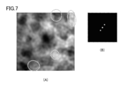
- FIG. 7A is a diagram illustrating a diffraction image of the high-resolution TEM image of FIG. 6, and FIG. 7B is a diagram illustrating imaging in a specific direction different from FIG.
- FIG. 7B obtained by Fourier transform of the diffraction image. It is a figure which shows the high-resolution TEM image after an annealing process about the sample of the comparative example 1.
- FIG. (A) shows a diffraction image of the high-resolution TEM image of FIG. 9, and (B) shows an image in a specific direction obtained by Fourier transform of the diffraction image.
- A) A diffraction image of the high-resolution TEM image of FIG. 9 is shown, and (B) is a diagram showing imaging in a specific direction different from FIG. 10 (B) obtained by Fourier transform of the diffraction image. It is a figure which shows the measurement result of a Seebeck coefficient. It is a figure which shows the measurement result of thermal conductivity.
- FIG. 6 is a graph plotting the relationship between the film thickness of the first layer and the grain spacing calculated by the measuring method 4.
- the present invention relates to a method for producing nanoparticles in which a base material composed of a semiconductor material composed of a base material element forms nanoparticles containing a base material element and a different element different from the base material element.
- a base material composed of a semiconductor material composed of a base material element forms nanoparticles containing a base material element and a different element different from the base material element.
- Laminating the first layer containing the elements and the second layer not containing the different elements alternately, and annealing the laminated body in which the first layer and the second layer are laminated.
- an annealing step for forming the nanoparticles In the laminating step, all the base material elements are included in at least one of the first layer and the second layer, and the second layer is formed thicker than the first layer.
- the thickness T 2 of the second layer is thicker than the thickness T 1 of the first layer, and preferably satisfies the relationship of T 1 ⁇ T 2 ⁇ 3T 1 .
- the desired particle spacing of the nanoparticles when the G d is formed in the laminating step, the thickness T 2 of the second layer, determined so as to satisfy the following equation (2) It is preferable to do.
- the thickness T 2 of the second layer determined in this way nanoparticles that satisfy the following formula (3) can be formed through the annealing step, in which the average particle spacing G m of the nanoparticles satisfies the following formula (3). it can.
- the derivation process of Formula (2) and Formula (3) will be described later.
- Average interval G m of the nanoparticles produced by the production method of the present invention is preferably 3 ⁇ 25 nm, more preferably from 3 ⁇ 10 nm. By setting such a grain interval, a high Seebeck coefficient and a large dimensionless figure of merit ZT can be obtained.
- the nanoparticle interval referred to in this specification refers to the shortest interval from one end to the other of the particles measured from an electron microscope (two-dimensional planar projection image), and the average interval refers to a sufficient number of particle intervals.
- the arithmetic mean of In this application, the arithmetic average of the intervals of 22 particles was calculated as the average interval. The interval between the nanoparticles can be adjusted by the thickness of the second layer.
- the thickness T 1 of the first layer is determined so as to satisfy the following formula (4) in the stacking step. Is preferred. Incidentally, by adopting the thickness T 1 of the first layer thus determined, through an annealing process, the average particle diameter X m of nanoparticles to form nanoparticles that satisfies Equation (5) below it can. The derivation process of Formula (4) and Formula (5) will be described later.
- the average particle diameter X m of the nanoparticles produced by the production method of the present invention is preferably 1 ⁇ 25 nm, more preferably 5 ⁇ 25 nm. By setting it as such a particle size, a high Seebeck coefficient and a large dimensionless figure of merit ZT can be obtained.
- the particle diameter means the long diameter of the particle measured from an image (two-dimensional planar projection image) obtained with an electron microscope, and the average particle diameter is a particle diameter of a sufficient number of particles. Arithmetic mean. In the present application, the arithmetic average of the particle sizes of 22 particles was calculated as the average particle size.
- the particle size of the nanoparticles is the thickness of the first layer, the thickness of the second layer, the atomic concentration of the different elements contained in the first layer, and the conditions for annealing treatment of the laminate in which the first layer and the second layer are laminated. It can be adjusted by etc.
- the thickness of the first layer is preferably 2 to 8 nm, and the thickness of the second layer is preferably 2.5 to 12 nm.
- Examples of the semiconductor material used as the base material in the manufacturing method include silicon germanium, gallium nitride, aluminum nitride, boron nitride, bismuth / tellurium: Bi 2 Te 3 , Pb 2 Te 3 , magnesium / silicide, and the like.
- the base material is silicon germanium
- the base material elements are Si and Ge
- examples of the different elements include Au, Cu, B, Al, and P.
- the base material is gallium nitride
- the base material elements are N and Ga
- examples of the different elements include In, Al, and B.
- the base material elements are Bi and Te or Pb, and examples of the different elements include Au, Cu, B, Al, and P.
- the base material elements are Mg and Si, and examples of the different elements include Au, Cu, B, Al, and P.
- a molecular beam epitaxy method MBE; Molecular Beam Epitaxy
- an electron beam method EB; Electron Beam
- a sputtering method a metal organic vapor phase epitaxy method (MOVPE;
- MOVPE metal organic vapor phase epitaxy method
- the atomic concentration of the different element in the first layer is preferably 0.5 to 50 atomic%.
- the first layer may be a single layer or multiple layers. In the case of a multilayer, a stacked body of a layer containing a base material element and a layer containing a different element may be used.
- the first layer and the second layer are included in at least one of the first layer and the second layer.
- the first layer can be formed so as to include Ge as a base material element
- the second layer may include Si as a base material element.
- both the first layer and the second layer can be formed to contain N and Ga.
- the first layer and the second layer may be stacked alternately, for example, the first layer and the second layer may be stacked 1 to 1000 times. The number of times the first layer is stacked substantially matches the number of nanoparticles in the thickness direction to be formed.
- the laminating step is a step of alternately laminating the first layer and the second layer on the substrate body in the embodiment of the present invention.
- a substrate body it is preferable that at least the uppermost layer in contact with the first layer is formed of a material capable of solid-dissolving the different element.
- the specific part may constitute a leak path
- a laminate including nanoparticles prepared by the method of the embodiment of the present invention is used as a thermoelectric material
- It can be a cause of deteriorating characteristics.
- the decrease in thermoelectric characteristics due to such a leak path is likely to manifest when the temperature difference generated in the thermoelectric material is large, for example, when the temperature difference is greater than 1K. Therefore, sufficient thermoelectric characteristics can be obtained even with a substrate body that does not have the uppermost layer.
- the temperature difference generated in the thermoelectric material is small, for example, 1K or less, the substrate body that does not have the uppermost layer. Also, sufficient thermoelectric characteristics can be obtained.
- the material for forming the uppermost layer is not limited as long as it is a material capable of dissolving the different elements contained in the first layer under the processing conditions in the annealing step. And organic substances such as Si, semiconductor, glass, ceramics, and PEDOT (poly (3,4-ethylenedioxythiophene)). Examples of the glass include amorphous glass and porous glass.
- a material having a low diffusion rate of different elements is more preferable. This is because the diffusion rate of the different elements in the uppermost layer is easier to control when the diffusion rate of the different elements is lower.
- the heterogeneous element is Au
- examples of materials that can dissolve Au include Si and Ge.
- Si has a lower diffusion rate of Au, so that Si is used as the uppermost layer. It is more preferable to form
- the diffusion rate of different elements in the material is expected to have a correlation with the affinity between the material and the different elements and the melting point of the material containing the different elements.
- the substrate body may be a laminate of the above-mentioned uppermost layer and other layers, or may be a single-layer body consisting of only the uppermost layer.
- a laminated body for example, a laminated body in which an uppermost layer is formed on a substrate can be used.
- the thickness of the uppermost layer is not limited as long as it is a thickness that can prevent a different element from concentrating on a specific portion of the first layer, but is preferably 5 nm or more, and 15 nm. More preferably, it is the above. This is because when the thickness is 5 nm or more, it is possible to sufficiently include different elements that diffuse under the processing conditions in the annealing step.
- an upper limit is not specifically limited, From a viewpoint of cost, it can be 30 nm or less, for example.
- the laminated body in which the first layer and the second layer are laminated is annealed to form nanoparticles in the base material.
- the annealing treatment here refers to a treatment of heating and then cooling until the atoms of the first layer diffuse. Therefore, the temperature and time of the annealing process vary depending on the material of the first layer. In addition, by controlling the temperature, time, and heating rate of the annealing treatment, the presence / absence of nanoparticle formation and the particle size of the formed nanoparticle can be adjusted.
- the lamination process and the annealing process may be performed independently or simultaneously.
- the annealing process is performed after the lamination process of alternately laminating the first layer and the second layer is completed. If they are performed simultaneously, the lamination process is performed under the conditions of the annealing process, and the annealing process is performed simultaneously in the lamination process.
- temperature control is easy, while when performed simultaneously, the number of steps can be reduced.
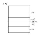
- FIG. 1 is a cross-sectional view schematically showing a laminated body in a state where the laminating process is completed once and an annealing process is not yet performed.
- a sapphire substrate 10 is prepared, and deposited in the order of Ge, Au, and Ge by MBE or EB, and an amorphous Ge (a-Ge) layer 21 / Au layer 22 / amorphous Ge.
- a first layer 20 made of an (a-Ge) layer 23 is formed, and then Si is deposited to form a second layer 30 made of an amorphous Si (a-Si) layer.
- Ge, Au, and Si raw materials are heated by an electron beam method in a cell to create a molecular beam.
- Such stacking of the first layer 20 and the second layer 30 is repeated 60 times to form a stacked body.
- the a-Ge layer 21 and the Au layer 22 are formed as separate layers in the first layer 20, but Ge and The deposition method is not limited as long as it is formed so as to include Au.
- the laminate is annealed to form nanoparticles.
- SiGe nanoparticles containing Au are formed in the base material made of Si and Ge.
- the mechanism for forming nanoparticles in this way is as follows. First, AuGe having a lower eutectic point than AuSi is activated in the first layer 20, and then the Si contained in the second layer 30 is taken in to form Au. It is understood that SiGe nanoparticles containing are formed.
- the base material composed of Si and Ge around the SiGe nanoparticles is amorphous SiGe, amorphous Ge, or amorphous Si.
- the thickness of the first layer 20 is 2.0 nm or more and less than 5.0 nm, and the thickness of the second layer 30 is 3.0 nm. It is preferable that the thickness of the Au layer 22 in the first layer 20 is 0.1 nm or more and 0.4 nm or less.
- the atomic concentration of Au in the first layer 20 is preferably 0.5 to 50 atomic%.
- the temperature of the annealing treatment in the annealing step can be appropriately selected from the range of 200 to 800 ° C., but in order to obtain nanoparticles having a particle size of 5 to 25 nm, the temperature of the annealing treatment is 300 to 700 ° C. Preferably there is.
- the particle size of the nanoparticles depends on the thickness of the first layer 20 and the second layer 30 and the atomic concentration of the different elements. For example, when the annealing temperature is 250 ° C., the nanoparticle size is 0.1 to 2 nm. When it is easy to obtain particles and the annealing temperature is 750 ° C., it is easy to obtain nanoparticles having a particle size of 20 to 100 nm.
- the annealing time in the annealing process performed after the lamination process is completed can be set to 1 to 120 minutes, for example.
- thermoelectric material As described above, in the base material composed of Si and Ge, a thin film containing Au-containing SiGe nanoparticles is formed, and when this is used as a thermoelectric material, it does not contain nanoparticles. Compared with, the thermal conductivity decreases, the Seebeck coefficient increases, and it functions as a thermoelectric material with a high figure of merit. The increase in the Seebeck coefficient is due to the occurrence of grain boundary scattering due to the presence of nanoparticles and the ability to confine carriers more effectively in the nanoparticles. Furthermore, according to the production method of the present invention, the interval between the nanoparticles can be optimized, and thereby grain boundary scattering can be more effectively generated, and thus the Seebeck coefficient can be further increased.
- the second embodiment is an example of the manufacturing method of the present invention when the base material is gallium nitride and the different element is In.
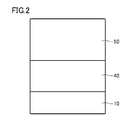
- FIG. 2 is a cross-sectional view schematically showing a stacked body in a state where the stacking process is completed once and an annealing process is not yet performed.
- a sapphire substrate 10 is prepared, and a first layer 40 made of an amorphous InGaN (a-InGaN) layer is formed by depositing Ga, N, and In by MBE or EB. Thereafter, Ga and N are deposited to form a second layer 50 made of an amorphous GaN (a-GaN) layer.
- a-GaN amorphous GaN
- MBE method Ga and In raw materials are heated in a cell by a resistance heating method to create a molecular beam.
- N supplies N 2 gas as radical nitrogen by radical discharge.
- Such stacking of the first layer 40 and the second layer 50 is repeated 60 times to form a stacked body.
- the laminate is annealed to form nanoparticles.
- GaN nanoparticles containing In are formed in the base material composed of Ga and N.
- the base material composed of Ga and N around the GaN nanoparticles is amorphous GaN.
- the thickness of the first layer 40 is 2.5 nm or more and less than 3.0 nm, and the thickness of the second layer 50 is 4.0 nm.
- the thickness is preferably 6.0 nm or less.
- the atomic concentration of In in the first layer 40 is preferably 0.1 to 80 atomic%.
- the temperature of the annealing treatment in the annealing step can be appropriately selected from the range of 150 to 1100 ° C. However, in order to obtain nanoparticles having a particle size of 1 to 10 nm, the temperature of the annealing treatment is 300 to 800 ° C. Preferably there is.
- the annealing time in the annealing process performed after the lamination process is completed can be set to 1 to 120 minutes, for example.
- thermoelectric material As described above, in the base material composed of Ga and N, a thin film including GaN nanoparticles containing In is formed, and when this is used as a thermoelectric material, it is not included by including nanoparticles. Compared with, the thermal conductivity decreases, the Seebeck coefficient increases, and it functions as a thermoelectric material with a high figure of merit. The increase in Seebeck coefficient is due to the occurrence of grain boundary scattering due to the presence of nanoparticles and the ability to effectively confine carriers in the nanoparticles. Furthermore, according to the production method of the present invention, the interval between the nanoparticles can be optimized, and thereby grain boundary scattering can be more effectively generated, and thus the Seebeck coefficient can be further increased.
- FIG. 20 is a cross-sectional view schematically showing a stacked body in a state where the stacking process has been completed once and an annealing process has not yet been performed.
- the substrate body 60 includes a sapphire substrate 10 and an uppermost layer 11 that is an amorphous Si (a-Si) layer.
- a-Si amorphous Si
- As the substrate body 60 first, the sapphire substrate 10 is prepared, and Si is deposited thereon by the MBE method or the EB method to form the uppermost layer 11. Since other processes are the same as those in the first embodiment, the description thereof is omitted.
- the laminate including nanoparticles produced according to this embodiment has a configuration in which Au is diffused in the uppermost layer 11.
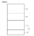
- FIG. 21 is a cross-sectional view schematically showing a stacked body in a state where the stacking process has been completed once and an annealing process has not yet been performed.
- the substrate body 70 includes a sapphire substrate 10 and an uppermost layer 12 which is an amorphous GaN (a-GaN) layer.
- a-GaN amorphous GaN
- As the substrate body 70 first, the sapphire substrate 10 is prepared, and Ga and N are deposited thereon by the MBE method to form the uppermost layer 12. Since other processes are the same as those in the second embodiment, the description thereof is omitted.
- the laminate including nanoparticles produced according to this embodiment has a configuration in which In is diffused in the uppermost layer 12.
- thermoelectric material of the present invention is a manufacturing method in which the thin film containing nanoparticles formed by annealing the laminate is used as it is in the above-described manufacturing method of nanoparticles. That is, the method for manufacturing a thermoelectric material of the present invention is a method for manufacturing a thermoelectric material including nanoparticles containing a base material element and a different element different from the base material element in a thin film made of a semiconductor material composed of the base material element.
- thermoelectric material composed of nanoparticles comprising: a laminating step of alternately laminating a first layer containing a different element and a second layer not containing the different element; An annealing step of annealing the laminated body in which the two layers are laminated to form nanoparticles in the thin film.
- all the base material elements are included in at least one of the first layer and the second layer, and the second layer is formed thicker than the first layer.
- the details of the laminating step and the annealing step are as described in the method for producing nanoparticles.
- thermoelectric material of the present invention is a thermoelectric material produced by the method for producing a thermoelectric material. That is, the thermoelectric material of the present invention contains nanoparticles, the average particle diameter of the nanoparticles is preferably 1 to 25 nm, more preferably 5 to 25 nm, and the interval between the nanoparticles is preferably 3 to 25 nm, more preferably 3 ⁇ 10 nm.
- a thermoelectric material having nanoparticles with such a particle spacing and particle size can obtain a high Seebeck coefficient and a large dimensionless figure of merit ZT.
- the Seebeck coefficient is preferably 1 mV / K or more, more preferably 2 mV / K or more, further preferably 3 mV / K or more, and the dimensionless figure of merit ZT is preferably 10 or more.
- thermoelectric material manufactured by the manufacturing method of the third or fourth embodiment has a configuration in which different elements are diffused in the uppermost layer of the substrate body.
- different elements are not concentrated and precipitated in a specific part, and the formation of a leak path can be prevented, even when the temperature difference generated in the thermoelectric material is increased, A high Seebeck coefficient can be obtained.
- Nanoparticles were formed by the manufacturing method of the first embodiment. Specifically, in the stacking step, a first layer composed of an a-Ge layer / Au layer / a-Ge layer is formed on a sapphire substrate, and each layer has a thickness of 1.3 to 1.9 nm / 0.2 nm / 1. Deposition was performed at 3 to 1.9 nm, and then Si was deposited to form a second layer composed of an a-Si layer in a thickness range of 2.6 to 5.2 nm. The concentration of Au in the first layer was 2.5 to 17 atomic%. And the process of laminating the first layer and the second layer was repeated 60 times.
- the laminate was left in an RTA furnace in a nitrogen atmosphere in an environment of 600 ° C. for 15 minutes to perform an annealing treatment and an annealing process was performed to form nanoparticles.
- the equation (2) and ( The relational expression 3) was derived from samples prepared by, for example, as measurement method 1-3 described below.
- the equation (4) and ( The relational expression 5) was derived from samples prepared by, for example, as measurement method 4 described below.
- MBE molecular beam epitaxy
- EB method electron beam method
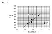
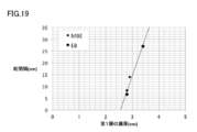
- the nanoparticles in the samples prepared by the measurement method 1-3 in the following manner to calculate the mean particle spacing G m, the relationship between the average particle distance G m and the thickness of the second layer in FIGS. 16 to 18 Plotted. Further, the nano-particles in the sample prepared by the measurement method 4, as follows to calculate the average particle diameter X m, a plot of average particle relationship size X m and the thickness of the first layer in FIG. 19.
- the measurement method 1 is a high-resolution TEM (Transmission Electron Microscopy) obtained after thinning to about 100 nm in the stacking direction by FIB (Focused Ion Beam) using an electron microscope (device name: JEM-2100F, manufactured by JEOL Ltd.). ) Image and an FFT image obtained by performing FFT (Fast Fourier Transform) transform and processing to make the periodic structure of the nanocrystal stand out, an average grain spacing G was calculated.
- Measurement method 4 In measurement method 4, the particle size X of the nanoparticles was calculated by Scherrer's equation based on the measurement result of X-ray diffraction (XRD). Table 1 shows the data of the designed film thickness of the first layer and the particle size X calculated by the measuring method 4 for six samples (Sample 1 to Sample 6), and FIG. 19 is a plot of the results of Table 1. is there.
- Nanoparticles were formed by the manufacturing method of the first embodiment. Specifically, in the stacking step, the first layer composed of the a-Ge layer / Au layer / a-Ge layer is formed on the sapphire substrate, and the thickness of each layer is 1.3 nm / 0.2 nm / 1.3 nm. Deposition was performed so as to have a thickness of 2.8 nm, and then Si was deposited, so that a second layer composed of an a-Si layer was deposited so as to have a thickness of 5.2 nm. And this process was repeated 60 times. Note that the atomic concentration of Au in the first layer was 2.5 atomic%.
- the laminated body was left to stand in an environment of 600 ° C. for 15 minutes in an RTA furnace (Rapid Thermal Anneal) in a nitrogen atmosphere to perform an annealing process to perform an annealing process.
- RTA furnace Rapid Thermal Anneal
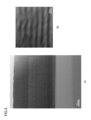
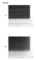
- FIG. 3A shows a bright field STEM (Scanning Transmission Electron Microscopy) image obtained using an electron microscope (device name: JEM-2100F, manufactured by JEOL Ltd.) after the lamination process and before the annealing process.
- FIG. 3B shows an enlarged image of the stacked portion of the first layer and the second layer in FIG. 3A and 3B, it was confirmed that the first layer and the second layer were alternately stacked.
- EDX energy dispersive X-ray spectroscopy
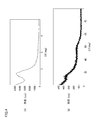
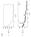
- FIG. 4 shows an X-ray diffraction pattern obtained by X-ray diffraction measurement performed using an X-ray diffractometer on the laminate after the lamination step and before the annealing step
- FIG. FIG. 4B shows a diffraction pattern on the high angle side
- 5 shows an X-ray diffraction pattern of the laminated body after the annealing step
- FIG. 5A shows a low-angle diffraction pattern
- FIG. 5B shows a high-angle diffraction pattern.
- a peak was observed before the annealing step (FIG. 4A), but the peak disappeared after the annealing step (FIG. 5A).
- the peak on the low angle side corresponds to the periodic structure in which the first layer and the second layer are repeatedly laminated, and this periodic structure was presumed to have disappeared by the annealing process.
- the peak P1 observed in FIG. 5 (B) corresponds to the crystal plane (111) of the SiGe crystal, and thus it was assumed that the SiGe crystal was formed by the annealing treatment.
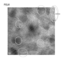
- FIG. 6 was obtained after the laminated body after the annealing process was thinned to about 100 nm by FIB (Focused Ion Beam) in the stacking direction using an electron microscope (device name: JEM-2100F, manufactured by JEOL Ltd.).
- a high resolution TEM (Transmission Electron Microscopy) image is shown.
- FIG. 6 a region surrounded by a dotted line is a region estimated to be crystallized.
- FIGS. 7A and 8A show diffraction images of the high-resolution TEM image of FIG. 6, and FIGS. 7B and 8B show FIGS. 7A and 8A, respectively.
- Fig. 4 shows imaging in different specific directions obtained by Fourier transform of a diffraction image.
- the grain size of the crystal grains was 5 to 14 nm, and the average grain size was 8 nm.
- the peak P1 corresponding to the crystal plane of SiGe is estimated to be 8.2 nm by applying the half width to Scherrer's formula and estimating the grain size of the crystal grains. It almost coincided with the actually measured value in the high resolution TEM image shown in FIG.
- the crystal grain interval was measured, it was 5 to 25 nm, and the average interval was 14 nm.
- Nanoparticles were produced by the same production method as in Example 1 except that the thickness of the second layer in the laminating step was 2.6 nm, that is, the thickness was made thinner than 2.8 nm of the total thickness of the first layer.
- FIG. 9 was obtained after the laminated body after the annealing process was thinned to about 100 nm by FIB (Focused Ion Beam) in the stacking direction using an electron microscope (device name: JEM-2100F, manufactured by JEOL Ltd.).
- a high resolution TEM (Transmission Electron Microscopy) image is shown.
- FIG. 9 a region surrounded by a dotted line is a region estimated to be crystallized.
- FIGS. 10A and 11A show diffraction images of the high-resolution TEM image of FIG. 9, and FIGS. 10B and 11B show the diffraction patterns of FIGS. 10A and 11A.
- Fig. 4 shows imaging in different specific directions obtained by Fourier transform of a diffraction image.
- the crystal grain size when the crystal grain size was measured, the crystal grain size was 4 to 15 nm, and the average grain size was 7 nm.
- the crystal grain interval when the crystal grain interval was measured, it was 0 to 3 nm, and the average interval was 1 nm.
- thermoelectric characteristics were evaluated.
- FIG. 12 shows the measurement results of the Seebeck coefficient of the samples of Example 1 and Comparative Example 1 and Dismukes, JP, et al., (1964) J. App. Phys. 35, 2899-2907 (JAP 352899). It is a figure which shows the Seebeck coefficient of the bulk SiGe which is.
- the sample of Example 1 shows a high value near 0.7 mV / K, which is higher than that of bulk SiGe. This is understood to be the effect of having nanoparticles. Moreover, it is thought that it is the effect by the space
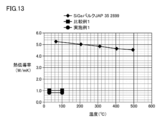
- FIG. 13 is a diagram showing the measurement results of the thermal conductivity of the samples of Example 1 and Comparative Example 1, and the thermal conductivity of bulk SiGe shown in JAP352899.
- the sample of Example 1 exhibited a low thermal conductivity of 1/5 or less compared to bulk SiGe. This is considered to be an effect due to the improvement of phonon scattering by having nanoparticles.
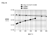
- FIG. 14 is a diagram showing the measurement results of the electrical conductivity of the samples of Example 1 and Comparative Example 1, and the electrical conductivity of bulk SiGe shown in JAP352899.
- FIG. 15 is a diagram showing the calculation result of the dimensionless figure of merit ZT of the samples of Example 1 and Comparative Example 1, and the dimensionless figure of merit ZT of bulk SiGe shown in JAPA352899. As shown in FIG. 15, the dimensionless figure of merit ZT of the sample of Example 1 was higher than that of the sample of Comparative Example 1 and bulk SiGe.
- Nanoparticles were formed by the manufacturing method of the first embodiment or the third embodiment. Specifically, first, a substrate body was prepared. As the substrate body, a substrate body composed of only a sapphire substrate and a substrate body provided with an uppermost layer composed of amorphous silicon (a-Si) on the sapphire substrate were prepared.
- a-Si amorphous silicon
- a first layer composed of a-Ge layer / Au layer / a-Ge layer is deposited on the substrate body at a thickness of 1.3 nm / 0.2 nm / 1.3 nm by a laminating process, and thereafter Si was deposited to deposit a second layer of a-Si layer with a thickness of 5.2 nm.
- the concentration of Au in the first layer was 3.3 to 4.7 atomic%.
- the process of laminating the first layer and the second layer was repeated 40 times. Thereafter, the laminate was left to stand in an environment of 500 ° C. for 15 minutes in an RTA furnace in a nitrogen atmosphere to perform an annealing process, and an annealing process was performed to form nanoparticles.
- sample 7 uses a substrate body made of only a sapphire substrate
- sample 8 uses a substrate body provided with a top layer of 15 nm thickness on the sapphire substrate
- sample 9 on the sapphire substrate.
- a substrate body provided with an uppermost layer having a thickness of 30 nm is used.
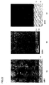
- a bright field STEM (Scanning Transmission Electron Microscopy) image was obtained using the electron microscope (device name: JEM-2100F, manufactured by JEOL Ltd.) for the laminates of Samples 7 to 9 prepared as described above.
- 22A, 22B, and 22C show bright-field STEM images of portions including the substrate 10 for the samples 7, 8, and 9, respectively.
- the portion that appears black in the layer on the sapphire substrate 10 is Au.
- EDX energy dispersive X-ray spectroscopy
- the thickness of the uppermost layer 11 is 5 nm, which is 1/3 of 15 nm in the sample 8
- Au is diffused into the uppermost layer 11 and Au concentrates and precipitates in a specific portion. I was able to predict that this could be prevented.
- thermoelectric characteristic measuring device device name: RZ2001i, manufactured by Ozawa Kagaku.
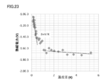
- FIG. 23 shows the measurement result of Sample 7
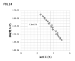
- FIG. 24 shows the measurement result of Sample 9.
- the slope of the thermoelectromotive force graph shown in FIGS. 23 and 24 represents the Seebet coefficient.
- thermoelectric characteristics are different between when the temperature difference is 1K or less and when the temperature difference is larger than 1K.
- Au concentrates and precipitates at the boundary portion with the sapphire substrate.
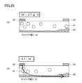
- FIGS. 25A and 25B can be considered.
- FIG. 25A shows a model when the temperature difference generated between the electrodes 83 and 84 is small, specifically when the temperature difference is 2K or less.
- FIG. 25B shows a model when the temperature difference generated between the electrodes 83 and 84 is large, specifically when the temperature difference exceeds 2K. In this case, it is considered that the bias of the carrier 81 is large, and the deposited portion 82 of Au can constitute a leak path.
- the atomic concentration of Au in the first layer was 4.7 atomic%.
- the laminated body was left to stand in an environment of 500 ° C. for 15 minutes in an RTA furnace in a nitrogen atmosphere to perform an annealing process to perform an annealing process.
- FIG. 26A shows an enlarged image of a stacked portion including the sapphire substrate 10 and the uppermost layer 11 of the stacked body before the annealing step.
- FIG. 26B shows an enlarged image of a stacked portion of a portion including the sapphire substrate 10 and the uppermost layer 11 of the stacked body after the annealing step.
Landscapes
- Chemical & Material Sciences (AREA)
- Inorganic Chemistry (AREA)
- Engineering & Computer Science (AREA)
- Manufacturing & Machinery (AREA)
- Physical Vapour Deposition (AREA)
- Powder Metallurgy (AREA)
- Physical Deposition Of Substances That Are Components Of Semiconductor Devices (AREA)
Abstract
Description
式(1)において、αは熱電材料のゼーベック係数(V/K)、Sは熱電材料の導電率(S/m)、κは熱電材料の熱伝導率(W/mK)である。Zは温度の逆数の次元を有し、この性能指数Zに絶対温度Tを乗じて得られるZTは無次元の値となる。そして、このZTを無次元性能指数といい、熱電材料の性能を表す指標として用いられている。
本発明は、母材元素で構成される半導体材料からなる母材中に、母材元素と母材元素とは異なる異種元素とを含むナノ粒子を形成するナノ粒子の製造方法であって、異種元素を含む第1層と、異種元素を含まない第2層とを交互に積層する積層工程と、第1層と第2層とが積層された積層体をアニール処理して、上記母材中に上記ナノ粒子を形成するアニール工程とを備える。上記積層工程において、母材元素の全ては、第1層または第2層の少なくとも一方に含まれ、第2層は第1層より厚く形成される。
式(3):Gm=(2.3±σ1)T2-(1.3±σ2)
式(2)および(3)において、σ1およびσ2は標準偏差であり、σ1は、0≦σ1≦0.1を満たし、σ2は、0≦σ2≦1.9を満たす。
式(5):Xm=(32±σ3)T1-(81±σ4)
式(4)および(5)において、σ3およびσ4は標準偏差であり、σ3は、0≦σ3≦7を満たし、σ4は、0≦σ4≦20を満たす。
第1の実施形態は、母材がシリコンゲルマニウムであり、異種元素がAuである場合の本発明の製造方法の一例である。図1は、積層工程が1回終了した状態であって、アニール処理をまだ行なっていない状態の積層体を模式的に示す断面図である。
第2の実施形態は、母材が窒化ガリウムであり、異種元素がInである場合の本発明の製造方法の一例である。図2は、積層工程が1回終了した状態であって、アニール処理をまだ行なっていない状態の積層体を模式的に示す断面図である。
第3の実施形態は、第1の実施形態とは、サファイア基板10の代わりに、基板体60を用いている点のみが異なる。図20は、積層工程が1回終了した状態であって、アニール処理をまだ行なっていない状態の積層体を模式的に示す断面図である。基板体60は、サファイア基板10と、アモルファスSi(a-Si)層である最上層11からなる。基板体60は、まずサファイア基板10を用意し、その上にMBE法またはEB法によりSiを堆積させて最上層11を形成する。その他の工程は、第1の実施形態と同様であるので説明を省略する。本実施形態により製造されたナノ粒子を含む積層体は、最上層11にAuが拡散している構成である。
第4の実施形態は、第2の実施形態とは、サファイア基板10の代わりに、基板体70を用いている点のみが異なる。図21は、積層工程が1回終了した状態であって、アニール処理をまだ行なっていない状態の積層体を模式的に示す断面図である。基板体70は、サファイア基板10と、アモルファスGaN(a-GaN)層である最上層12からなる。基板体70は、まずサファイア基板10を用意し、その上にMBE法によりGa、Nを堆積させて最上層12を形成する。その他の工程は、第2の実施形態と同様であるので説明を省略する。本実施形態により製造されたナノ粒子を含む積層体は、最上層12にInが拡散している構成である。
本発明の熱電材料の製造方法は、上記ナノ粒子の製造方法において、積層体をアニール処理して形成されたナノ粒子を含む薄膜をそのまま熱電材料とする製造方法である。すなわち、本発明の熱電材料の製造方法は、母材元素で構成される半導体材料からなる薄膜中に、母材元素と母材元素とは異なる異種元素とを含むナノ粒子を備える熱電材料の製造方法であって、ナノ粒子からなる熱電材料を製造する方法であって、異種元素を含む第1層と、異種元素を含まない第2層を交互に積層する積層工程と、第1層と第2層とが積層された積層体をアニール処理して、薄膜中にナノ粒子を形成するアニール工程とを備える。積層工程において、母材元素の全ては、第1層または第2層の少なくとも一方に含まれ、第2層は前記第1層より厚く形成される。積層工程およびアニール工程の詳細については、上記ナノ粒子の製造方法で説明したとおりである。このようにして熱電材料を製造することにより、高いゼーベック係数と、大きい無次元性能指数ZTを得ることができる。
本発明の熱電材料は、上記熱電材料の製造方法により製造される熱電材料である。すなわち、本発明の熱電材料はナノ粒子を含み、ナノ粒子の平均粒径は好ましくは1~25nm、さらに好ましくは5~25nmであり、ナノ粒子の間隔は好ましくは3~25nm、さらに好ましくは3~10nmである。このような粒間隔、粒径のナノ粒子を有する熱電材料は、高いゼーベック係数と、大きい無次元性能指数ZTを得ることができる。ゼーベック係数が好ましくは1mV/K以上、より好ましくは2mV/K以上、さらに好ましくは3mV/K以上であって、無次元性能指数ZTが好ましくは10以上である。
第1の実施形態の製造方法によりナノ粒子を形成した。具体的には、積層工程において、サファイア基板上にa-Ge層/Au層/a-Ge層からなる第1層を、各層の厚みが1.3~1.9nm/0.2nm/1.3~1.9nmで堆積し、その後Siを堆積させてa-Si層からなる第2層を、厚みが2.6~5.2nmの範囲で堆積した。第1層中のAuの濃度は、2.5~17原子%とした。そして、第1層および第2層を積層する工程を60回繰り返して行なった。その後、積層体を窒素雰囲気のRTA炉で600℃の環境下に15分間放置してアニール処理を施しアニール工程を行ない、ナノ粒子を形成した。このようにして作成した試料から、たとえば、以下に説明する計測法1~3のように、第2層の厚さとナノ粒子の平均間隔Gmとの関係を算出し、式(2)および(3)の関係式を導いた。また、このようにして作製した試料から、たとえば、以下に説明する計測法4のよう、第1層の厚さとナノ粒子の平均粒径Xmとの関係を算出し、式(4)および(5)の関係式を導いた。
計測法1は、電子顕微鏡(装置名:JEM-2100F、日本電子社製)を用いて、積層方向にFIB(Focused Ion Beam)で約100nmに薄片化した後に得た高分解TEM(Transmission Electron Microscopy)像、およびFFT(Fast Fourier Transform)変換してナノ結晶の周期構造を際立たせる処理を行ったFFT像から実測して、平均の粒間隔Gを算出した。図16は、第2層の膜厚と計測法1により算出した平均の粒間隔Gの関係をプロットした図である。図16に示す結果から、最小二乗法により式(3a);
G=2.3T2
が導かれた。
計測法2は、ラマン散乱測定から結晶化率ηを測定し、かかる結晶化率ηと、高分解TEM(Transmission Electron Microscopy)像から実測して算出したナノ粒子の平均半径rとを用い、ナノ粒子が均一に分散しているものと仮定することで導かれる式(6);
G=2(r/η(1/3)-r)
から算出した。図17は、第2層の膜厚と計測法2により算出した粒間隔Gの関係をプロットした図である。図17に示す結果から最小二乗法により式(3b);
G=2.3T2-0.5
が導かれた。
計測法3においては、ラマン散乱測定から結晶化率ηを測定し、X線回折(XRD)の測定結果に基づきシェラーの式によりナノ粒子の半径rを算出した。そして、結晶化率ηと、半径rを用いて、式(6)から粒間隔Gを算出した。図18は、第2層の膜厚と計測法3により算出した粒間隔Gの関係をプロットした図である。図18に示す結果から式(3c);
G=2.4T2-3.5
が導かれた。
計測法4においては、X線回折(XRD)の測定結果に基づきシェラーの式によりナノ粒子の粒径Xを算出した。表1は、6つの試料(試料1~試料6)について第1層の設計膜厚と計測法4により算出した粒径Xのデータを示し、図19は、表1の結果をプロットした図である。

X=32T1-81
が導かれた。
第1の実施形態の製造方法によりナノ粒子を形成した。具体的には、積層工程において、サファイア基板上にa-Ge層/Au層/a-Ge層からなる第1層を、各層の厚みが1.3nm/0.2nm/1.3nmであり合計2.8nmとなるように堆積し、その後Siを堆積させてa-Si層からなる第2層を、厚みが5.2nmとなるように堆積した。そして、かかる工程を60回繰り返して行なった。なお、第1層中のAuの原子濃度は2.5原子%とした。その後、積層体を窒素雰囲気のRTA炉(Rapid Thermal Anneal:高速アニール炉)で600℃の環境下に15分間放置してアニール処理を施しアニール工程を行なった。なお、ナノ粒子の所望の粒径Xdを10nm、ナノ粒子の所望の粒間隔Gdを12nmとしたので、本実施例における第1層の厚さT1の2.8mmは、式(4)を満たすように決定されており、第2層の厚さT2の5.2nmは、式(2)を満たすように決定されている。
積層工程における第2層の厚みを2.6nm、すなわち第1層の合計厚さの2.8nmより薄くした点以外は、実施例1と同様の製造方法によりナノ粒子を製造した。
実施例1と比較例1の試料について、以下のようにゼーベック係数、熱伝導率、導電率を測定し熱電材料として用いた場合の熱電特性を評価した。
実施例1および比較例1の試料について、熱電特性評価装置(装置名:ZEM3、アルバック理工社製)でゼーベック係数を測定した。図12は、実施例1および比較例1の試料のゼーベック係数の測定結果と、Dismukes, J.P., et al., (1964) J. App. Phys. 35, 2899-2907(JAP352899)に示されているバルクのSiGeのゼーベック係数を示す図である。実施例1の試料は、0.7mV/K近くの高い値を示しており、バルクのSiGeと比較して高い値となっている。これはナノ粒子を有することによる効果であると解される。また比較例1の試料と比較して高い値となっているのは、ナノ粒子の間隔がナノ粒子の粒径に対して最適化されたことによる効果であると考えられる。
実施例1および比較例1の試料について、熱伝導率測定装置(装置名:TM3、ベテル社製、2ω法で測定)で熱伝導率を測定した。図13は、実施例1および比較例1の試料の熱伝導率の測定結果と、JAP352899に示されているバルクのSiGeの熱伝導率を示す図である。実施例1の試料は、バルクのSiGeと比較して5分の1以下の低い熱伝導率を示した。これはナノ粒子を有することによりフォノン散乱が向上したことによる効果であると考えられる。
実施例1および比較例1の試料について、導電率測定装置(装置名:ZEM3、アルバック理工社製)で導電率を測定した。図14は、実施例1および比較例1の試料の導電率の測定結果と、JAP352899に示されているバルクのSiGeの導電率を示す図である。
以上の測定値に基づき、実施例1および比較例1の試料について無次元性能指数ZTを算出した。図15は、実施例1および比較例1の試料の無次元性能指数ZTの算出結果と、JAP352899に示されているバルクのSiGeの無次元性能指数ZTを示す図である。図15に示すように、実施例1の試料の無次元性能指数ZTは、比較例1の試料およびバルクのSiGeと比較して、高い値となった。
(試料7~9)
第1の実施形態または第3の実施形態の製造方法によりナノ粒子を形成した。具体的には、まず基板体を用意した。基板体は、サファイア基板のみからなる基板体と、サファイア基板上にアモルファスシリコン(a-Si)からなる最上層を設けた基板体とを準備した。そして、基板体上に、積層工程により、a-Ge層/Au層/a-Ge層からなる第1層を、各層の厚みが1.3nm/0.2nm/1.3nmで堆積し、その後Siを堆積させてa-Si層からなる第2層を5.2nmの厚みで堆積した。第1層中のAuの濃度は、3.3~4.7原子%とした。そして、第1層および第2層を積層する工程を40回繰り返して行なった。その後、積層体を窒素雰囲気のRTA炉で500℃の環境下に15分間放置してアニール処理を施しアニール工程を行ない、ナノ粒子を形成した。

試料7および試料9について、表面に二つの電極を設けて、二つの電極間に温度差をかけ熱電特性測定装置(装置名:RZ2001i、オザワ科学製)を用いて熱起電力を測定した。図23は試料7の測定結果を示し、図24は、試料9の測定結果を示す。図23および図24に示す熱起電力のグラフの傾きがゼーベット係数を表す。試料7を用いた場合は、図23に示すように、温度差が1K以下の場合に、2mV/Kのゼーベック係数が得られて高性能の熱電材料を構成できることがわかった。試料9を用いた場合は、図24に示すように、4Kを超える温度差が生じた場合であっても、1.3mV/Kのゼーベック係数が得られて高性能の熱電材料を構成できることがわかった。
試料7について、図23に示すように、温度差が1K以下である場合と、温度差が1Kより大きい場合とで、熱電特性に差が生じている理由について考察する。試料7においては、図22(A)に示すように、Auがサファイア基板との境界部分に集中して析出する。かかるAuの析出部分が、電極部とキャリヤを介し電気的に導通し得る状態になると、リークパスを構成することになり、熱電特性を低下させることになると考えられる。具体的には、図25(A)、(B)に示すモデルが考えられる。図25(A)は、電極83,84の間に生じさせる温度差が小さい場合、具体的には温度差が2K以下である場合のモデルを示す。この場合、キャリヤ81の偏りが小さく、Auの析出部分82がリークパスを構成しないと考えられる。図25(B)は、電極83,84間に生じさせる温度差が大きい場合、具体的には温度差が2Kを超える場合のモデルを示す。この場合、キャリア81の偏りが大きく、Auの析出部分82がリークパスを構成し得ると考えられる。
第3の実施形態の製造方法によりナノ粒子を形成した。具体的には、サファイア基板上にアモルファスシリコン(a-Si)からなる厚さ30nmの最上層を形成した。その上に積層工程において、a-Ge層/Au層/a-Ge層からなる第1層を、各層の厚みが1.3nm/0.2nm/1.3nmであり合計2.8nmとなるように堆積し、その後Siを堆積させてa-Si層からなる第2層を、厚みが5.2nmとなるように堆積した。そして、第1層および第2層を積層する工程を40回繰り返して行なった。なお、第1層中のAuの原子濃度は4.7原子%とした。その後、積層体を窒素雰囲気のRTA炉で500℃の環境下に15分間放置してアニール処理を施しアニール工程を行なった。なお、ナノ粒子の所望の粒径Xdを10nm、ナノ粒子の所望の粒間隔Gdを12nmとしたので、本実施例における第1層の厚さT1の2.8mmは、式(4)を満たすように決定されており、第2層の厚さT2の5.2nmは、式(2)を満たすように決定されている。
Claims (17)
- 母材元素で構成される半導体材料からなる母材中に、前記母材元素と前記母材元素とは異なる異種元素とを含むナノ粒子を形成するナノ粒子の製造方法であって、
前記異種元素を含む第1層と、前記異種元素を含まない第2層とを交互に積層する積層工程と、
前記第1層と前記第2層とが積層された積層体をアニール処理して、前記母材中に前記ナノ粒子を形成するアニール工程とを備え、
前記積層工程において、前記母材元素は、前記第1層または前記第2層の少なくとも一方に含まれ、前記第2層は前記第1層より厚く形成される、ナノ粒子の製造方法。 - 形成されるナノ粒子の所望の粒間隔をGdとした場合に、前記積層工程において、前記第2層の厚さT2は、以下の式(2)を満たすように決定し、
前記アニール工程において形成されるナノ粒子の平均粒間隔Gmは、前記積層工程における前記第2層の厚さT2との間で、以下の式(3)を満たす、請求項1に記載のナノ粒子の製造方法。
式(2):Gd=(2.3±σ1)T2-(1.3±σ2)(単位nm)
式(3):Gm=(2.3±σ1)T2-(1.3±σ2)(単位nm)
(式(2)および(3)において、σ1およびσ2は標準偏差であり、σ1は、0≦σ1≦0.1であり、σ2は、0≦σ2≦1.9を満たす。) - 形成されるナノ粒子の所望の粒径をXdとした場合に、前記積層工程において、前記第1層の厚さT1は、以下の式(4)を満たすように決定し、
前記アニール工程において形成されるナノ粒子の平均粒径Xmは、前記積層工程における前記第1層の厚さT1との間で、以下の式(5)を満たす、請求項1または請求項2に記載のナノ粒子の製造方法。
式(4):Xd=(32±σ3)T1-(81±σ4)(単位nm)
式(5):Xm=(32±σ3)T1-(81±σ4)(単位nm)
(式(4)および(5)において、σ3およびσ4は標準偏差であり、σ3は、0≦σ3≦7を満たし、σ4は、0≦σ4≦20を満たす。) - 前記母材元素はSiおよびGeであり、
前記異種元素は、Au、Cu、BまたはAlであって、
前記積層工程において、前記第1層は前記母材元素としてGeを含み、前記第2層は前記母材元素としてSiを含む、請求項1~請求項3のいずれか1項に記載のナノ粒子の製造方法。 - 前記母材元素はNおよびGaであり、
前記異種元素は、InまたはAlであって、
前記積層工程において、前記第1層および前記第2層は前記母材元素としてNおよびGaを含む、請求項1~請求項3のいずれか1項に記載のナノ粒子の製造方法。 - 前記積層工程において、前記第1層の厚さは2~8nmであり、
前記アニール工程において形成される前記ナノ粒子は、平均粒径が1~25nmであり、平均間隔が3~25nmである、請求項1~請求項5のいずれか1項に記載のナノ粒子の製造方法。 - 前記アニール工程は、前記積層工程の後に行なう、請求項1~請求項6のいずれか1項に記載のナノ粒子の製造方法。
- 前記アニール工程は、前記積層工程と同時に行なう、請求項1~請求項6のいずれか1項に記載のナノ粒子の製造方法。
- 前記積層工程は、基板体上に前記第1層と前記第2層とを交互に積層する工程であり、 前記基板体の、少なくとも前記第1層と接する最上層は、前記異種元素を固溶可能な材料によって形成されている、請求項1~請求項8のいずれか1項に記載のナノ粒子の製造方法。
- 前記基板体の前記最上層は、Si、半導体、ガラス、セラミックス、または有機物によって形成されている、請求項9に記載のナノ粒子の製造方法。
- 前記母材元素はSiおよびGeであり、
前記異種元素は、Au、Cu、BまたはAlであって、
前記基板体の前記最上層はSiによって形成されている、請求項10に記載のナノ粒子の製造方法。 - 前記基板体の前記最上層の厚さが5nm以上である、請求項9~請求項11に記載のナノ粒子の製造方法。
- 母材元素で構成される半導体材料からなる薄膜中に、前記母材元素と前記母材元素とは異なる異種元素とを含むナノ粒子を備える熱電材料の製造方法であって、
前記異種元素を含む第1層と、前記異種元素を含まない第2層を交互に積層する積層工程と、
前記第1層と前記第2層とが積層された積層体をアニール処理して、前記薄膜中に前記ナノ粒子を形成するアニール工程とを備え、
前記積層工程において、前記母材元素は、前記第1層または前記第2層の少なくとも一方に含まれ、前記第2層は前記第1層より厚く形成される、熱電材料の製造方法。 - 前記積層工程は、基板体上に前記第1層と前記第2層とを交互に積層する工程であり、 前記基板体の、少なくとも前記第1層と接する最上層は、前記異種元素を固溶可能な材料によって形成されている、請求項13に記載の熱電材料の製造方法。
- 請求項13または請求項14に記載の製造方法により製造される熱電材料。
- 前記ナノ粒子の平均粒径は1~25nmであり、前記ナノ粒子の平均間隔が3~25nmである、請求項13または請求項14に記載の製造方法により製造される熱電材料。
- 前記基板体中に前記異種元素が拡散している、請求項14に記載の製造方法により製造される熱電材料。
Priority Applications (2)
| Application Number | Priority Date | Filing Date | Title |
|---|---|---|---|
| US14/895,266 US20160126440A1 (en) | 2013-06-04 | 2014-05-30 | Method of producing nanoparticles, method of producing thermoelectric material, and thermoelectric material |
| JP2015521431A JPWO2014196475A1 (ja) | 2013-06-04 | 2014-05-30 | ナノ粒子の製造方法、熱電材料の製造方法および熱電材料 |
Applications Claiming Priority (6)
| Application Number | Priority Date | Filing Date | Title |
|---|---|---|---|
| JP2013-117932 | 2013-06-04 | ||
| JP2013117932 | 2013-06-04 | ||
| JP2013226739 | 2013-10-31 | ||
| JP2013-226739 | 2013-10-31 | ||
| PCT/JP2014/054868 WO2014196233A1 (ja) | 2013-06-04 | 2014-02-27 | ナノ粒子の製造方法、熱電材料の製造方法および熱電材料 |
| JPPCT/JP2014/054868 | 2014-02-27 |
Publications (1)
| Publication Number | Publication Date |
|---|---|
| WO2014196475A1 true WO2014196475A1 (ja) | 2014-12-11 |
Family
ID=52007889
Family Applications (2)
| Application Number | Title | Priority Date | Filing Date |
|---|---|---|---|
| PCT/JP2014/054868 Ceased WO2014196233A1 (ja) | 2013-06-04 | 2014-02-27 | ナノ粒子の製造方法、熱電材料の製造方法および熱電材料 |
| PCT/JP2014/064468 Ceased WO2014196475A1 (ja) | 2013-06-04 | 2014-05-30 | ナノ粒子の製造方法、熱電材料の製造方法および熱電材料 |
Family Applications Before (1)
| Application Number | Title | Priority Date | Filing Date |
|---|---|---|---|
| PCT/JP2014/054868 Ceased WO2014196233A1 (ja) | 2013-06-04 | 2014-02-27 | ナノ粒子の製造方法、熱電材料の製造方法および熱電材料 |
Country Status (4)
| Country | Link |
|---|---|
| US (1) | US20160126440A1 (ja) |
| JP (1) | JPWO2014196475A1 (ja) |
| TW (1) | TW201512077A (ja) |
| WO (2) | WO2014196233A1 (ja) |
Cited By (9)
| Publication number | Priority date | Publication date | Assignee | Title |
|---|---|---|---|---|
| JP2017050505A (ja) * | 2015-09-04 | 2017-03-09 | 株式会社日立製作所 | 熱電変換材料および熱電変換モジュール |
| JP2017216388A (ja) * | 2016-06-01 | 2017-12-07 | 住友電気工業株式会社 | 熱電材料、熱電素子、光センサおよび熱電材料の製造方法 |
| WO2018043478A1 (ja) * | 2016-08-31 | 2018-03-08 | 住友電気工業株式会社 | 熱電変換材料、熱電変換素子および熱電変換モジュール |
| JPWO2017002514A1 (ja) * | 2015-06-30 | 2018-04-19 | 住友電気工業株式会社 | 熱電材料、熱電素子、光センサおよび熱電材料の製造方法 |
| JP2018142564A (ja) * | 2017-02-27 | 2018-09-13 | 株式会社日立製作所 | 熱電変換材料及びその製造方法 |
| WO2019244428A1 (ja) * | 2018-06-18 | 2019-12-26 | 住友電気工業株式会社 | 熱電変換材料、熱電変換素子、熱電変換モジュール、光センサおよび熱電変換材料の製造方法 |
| US11716903B2 (en) | 2018-09-03 | 2023-08-01 | Sumitomo Electric Industries, Ltd. | Thermoelectric conversion element, thermoelectric conversion module, optical sensor, method of producing thermoelectric conversion material, and method of producing thermoelectric conversion element |
| US11737364B2 (en) | 2018-03-20 | 2023-08-22 | Sumitomo Electric Industries, Ltd. | Thermoelectric conversion material, thermoelectric conversion element, thermoelectric conversion module, and optical sensor |
| US12029127B2 (en) | 2019-07-03 | 2024-07-02 | Sumitomo Electric Industries, Ltd. | Thermoelectric conversion material, thermoelectric conversion element, thermoelectric conversion module, and light sensor |
Families Citing this family (3)
| Publication number | Priority date | Publication date | Assignee | Title |
|---|---|---|---|---|
| US20160315243A1 (en) * | 2015-04-22 | 2016-10-27 | The Regents Of The University Of California | Charged particle beam processing of thermoelectric materials |
| JP6816384B2 (ja) * | 2016-05-27 | 2021-01-20 | 大同特殊鋼株式会社 | ホイスラー型鉄系熱電材料 |
| CN119400310B (zh) * | 2024-10-15 | 2026-02-13 | 山东大学深圳研究院 | 一种纳米层状结构材料制备过程的模拟方法、应用和系统 |
Citations (3)
| Publication number | Priority date | Publication date | Assignee | Title |
|---|---|---|---|---|
| JPH10242535A (ja) * | 1997-02-27 | 1998-09-11 | Central Res Inst Of Electric Power Ind | 熱電材料及びその製造方法 |
| US20080001127A1 (en) * | 2006-06-19 | 2008-01-03 | The Regents Of The University Of California | High efficiency thermoelectric materials based on metal/semiconductor nanocomposites |
| WO2012026678A2 (en) * | 2010-08-26 | 2012-03-01 | Lg Innotek Co., Ltd. | Thermoelectric module comprising thermoelectric element doped with nanoparticles and manufacturing method of the same |
Family Cites Families (2)
| Publication number | Priority date | Publication date | Assignee | Title |
|---|---|---|---|---|
| US7465871B2 (en) * | 2004-10-29 | 2008-12-16 | Massachusetts Institute Of Technology | Nanocomposites with high thermoelectric figures of merit |
| US8778214B2 (en) * | 2009-09-25 | 2014-07-15 | Northwestern University | Thermoelectrics compositions comprising nanoscale inclusions in a chalcogenide matrix |
-
2014
- 2014-02-27 WO PCT/JP2014/054868 patent/WO2014196233A1/ja not_active Ceased
- 2014-05-30 JP JP2015521431A patent/JPWO2014196475A1/ja active Pending
- 2014-05-30 WO PCT/JP2014/064468 patent/WO2014196475A1/ja not_active Ceased
- 2014-05-30 US US14/895,266 patent/US20160126440A1/en not_active Abandoned
- 2014-06-04 TW TW103119432A patent/TW201512077A/zh unknown
Patent Citations (3)
| Publication number | Priority date | Publication date | Assignee | Title |
|---|---|---|---|---|
| JPH10242535A (ja) * | 1997-02-27 | 1998-09-11 | Central Res Inst Of Electric Power Ind | 熱電材料及びその製造方法 |
| US20080001127A1 (en) * | 2006-06-19 | 2008-01-03 | The Regents Of The University Of California | High efficiency thermoelectric materials based on metal/semiconductor nanocomposites |
| WO2012026678A2 (en) * | 2010-08-26 | 2012-03-01 | Lg Innotek Co., Ltd. | Thermoelectric module comprising thermoelectric element doped with nanoparticles and manufacturing method of the same |
Cited By (14)
| Publication number | Priority date | Publication date | Assignee | Title |
|---|---|---|---|---|
| JPWO2017002514A1 (ja) * | 2015-06-30 | 2018-04-19 | 住友電気工業株式会社 | 熱電材料、熱電素子、光センサおよび熱電材料の製造方法 |
| US10944037B2 (en) | 2015-06-30 | 2021-03-09 | Sumitomo Electric Industries, Ltd. | Thermoelectric material, thermoelectric element, optical sensor, and method for manufacturing thermoelectric material |
| JP2017050505A (ja) * | 2015-09-04 | 2017-03-09 | 株式会社日立製作所 | 熱電変換材料および熱電変換モジュール |
| JP2017216388A (ja) * | 2016-06-01 | 2017-12-07 | 住友電気工業株式会社 | 熱電材料、熱電素子、光センサおよび熱電材料の製造方法 |
| WO2018043478A1 (ja) * | 2016-08-31 | 2018-03-08 | 住友電気工業株式会社 | 熱電変換材料、熱電変換素子および熱電変換モジュール |
| JPWO2018043478A1 (ja) * | 2016-08-31 | 2019-06-24 | 住友電気工業株式会社 | 熱電変換材料、熱電変換素子および熱電変換モジュール |
| JP2018142564A (ja) * | 2017-02-27 | 2018-09-13 | 株式会社日立製作所 | 熱電変換材料及びその製造方法 |
| US11737364B2 (en) | 2018-03-20 | 2023-08-22 | Sumitomo Electric Industries, Ltd. | Thermoelectric conversion material, thermoelectric conversion element, thermoelectric conversion module, and optical sensor |
| WO2019244428A1 (ja) * | 2018-06-18 | 2019-12-26 | 住友電気工業株式会社 | 熱電変換材料、熱電変換素子、熱電変換モジュール、光センサおよび熱電変換材料の製造方法 |
| JP7296377B2 (ja) | 2018-06-18 | 2023-06-22 | 住友電気工業株式会社 | 熱電変換材料、熱電変換素子、熱電変換モジュール、光センサおよび熱電変換材料の製造方法 |
| JPWO2019244428A1 (ja) * | 2018-06-18 | 2021-07-15 | 住友電気工業株式会社 | 熱電変換材料、熱電変換素子、熱電変換モジュール、光センサおよび熱電変換材料の製造方法 |
| US11758813B2 (en) | 2018-06-18 | 2023-09-12 | Sumitomo Electric Industries, Ltd. | Thermoelectric conversion material, thermoelectric conversion element, thermoelectric conversion module, optical sensor, and method for manufacturing thermoelectric conversion material |
| US11716903B2 (en) | 2018-09-03 | 2023-08-01 | Sumitomo Electric Industries, Ltd. | Thermoelectric conversion element, thermoelectric conversion module, optical sensor, method of producing thermoelectric conversion material, and method of producing thermoelectric conversion element |
| US12029127B2 (en) | 2019-07-03 | 2024-07-02 | Sumitomo Electric Industries, Ltd. | Thermoelectric conversion material, thermoelectric conversion element, thermoelectric conversion module, and light sensor |
Also Published As
| Publication number | Publication date |
|---|---|
| JPWO2014196475A1 (ja) | 2017-02-23 |
| WO2014196233A1 (ja) | 2014-12-11 |
| US20160126440A1 (en) | 2016-05-05 |
| TW201512077A (zh) | 2015-04-01 |
Similar Documents
| Publication | Publication Date | Title |
|---|---|---|
| JPWO2014196475A1 (ja) | ナノ粒子の製造方法、熱電材料の製造方法および熱電材料 | |
| JP6269352B2 (ja) | 熱電材料、熱電モジュール、光センサおよび熱電材料の製造方法 | |
| Ishibe et al. | Methodology of thermoelectric power factor enhancement by controlling nanowire interface | |
| Yang et al. | Enhanced thermoelectric properties in bulk nanowire heterostructure-based nanocomposites through minority carrier blocking | |
| Westover et al. | Photoluminescence, thermal transport, and breakdown in Joule-heated GaN nanowires | |
| Gadea et al. | Silicon-based nanostructures for integrated thermoelectric generators | |
| Sun et al. | Enhanced thermoelectric properties of n-type Bi2Te2. 7Se0. 3 thin films through the introduction of Pt nanoinclusions by pulsed laser deposition | |
| JP6927039B2 (ja) | 熱電材料、熱電素子、光センサおよび熱電材料の製造方法 | |
| Andrews et al. | Atomic-level control of the thermoelectric properties in polytypoid nanowires | |
| Park et al. | Effect of grain size on thermal transport in post-annealed antimony telluride thin films | |
| JP2015135939A5 (ja) | ||
| US11631795B2 (en) | Nanocomposite comprising semiconductor and metal nanoparticles, and assemblies | |
| Lin et al. | Effect of substrate temperature on the thermoelectric properties of the Sb2Te3 thin films deposition by using thermal evaporation method | |
| Lee et al. | Effect of electronic contribution on temperature-dependent thermal transport of antimony telluride thin film | |
| JP6502193B2 (ja) | シリコン微結晶複合体膜、熱電材料及びそれらの製造方法 | |
| CN109219894B (zh) | 热电材料、热电元件、光学传感器和热电材料的制造方法 | |
| Bae et al. | Growth of ZnO nanorod arrays by hydrothermal method using homo‐seed layers annealed at various temperatures | |
| Yang et al. | Scalable synthesis of two-dimensional antimony telluride nanoplates down to a single quintuple layer | |
| Conley et al. | Stability of pseudomorphic and compressively strained Ge1-xSnx thin films under rapid thermal annealing | |
| WO2011135975A1 (ja) | SiGe積層薄膜それを用いた赤外線センサ | |
| Noh | Aluminum silicide microparticles transformed from aluminum thin films by hypoeutectic interdiffusion | |
| CN114944423B (zh) | 一种锰碲共掺杂锗双层量子点材料及其制备方法和应用 | |
| TWI529983B (zh) | 具多層結構的熱電複合材料 | |
| Ravindra et al. | Thermoelectrics: material candidates and structures I–chalcogenides and silicon-germanium alloys | |
| KR20190106068A (ko) | 일차원 전이금속 칼코젠 화합물 및 일차원 전이금속 칼코젠 화합물 배선, 및 이를 포함하는 전자 장치 |
Legal Events
| Date | Code | Title | Description |
|---|---|---|---|
| 121 | Ep: the epo has been informed by wipo that ep was designated in this application |
Ref document number: 14807585 Country of ref document: EP Kind code of ref document: A1 |
|
| ENP | Entry into the national phase |
Ref document number: 2015521431 Country of ref document: JP Kind code of ref document: A |
|
| WWE | Wipo information: entry into national phase |
Ref document number: 14895266 Country of ref document: US |
|
| NENP | Non-entry into the national phase |
Ref country code: DE |
|
| 122 | Ep: pct application non-entry in european phase |
Ref document number: 14807585 Country of ref document: EP Kind code of ref document: A1 |