WO2014196472A1 - 電力供給システム、電力管理装置、電力管理方法および電力管理プログラム - Google Patents
電力供給システム、電力管理装置、電力管理方法および電力管理プログラム Download PDFInfo
- Publication number
- WO2014196472A1 WO2014196472A1 PCT/JP2014/064449 JP2014064449W WO2014196472A1 WO 2014196472 A1 WO2014196472 A1 WO 2014196472A1 JP 2014064449 W JP2014064449 W JP 2014064449W WO 2014196472 A1 WO2014196472 A1 WO 2014196472A1
- Authority
- WO
- WIPO (PCT)
- Prior art keywords
- power
- storage device
- amount
- devices
- predetermined value
- Prior art date
- Legal status (The legal status is an assumption and is not a legal conclusion. Google has not performed a legal analysis and makes no representation as to the accuracy of the status listed.)
- Ceased
Links
Images








Classifications
-
- G—PHYSICS
- G05—CONTROLLING; REGULATING
- G05F—SYSTEMS FOR REGULATING ELECTRIC OR MAGNETIC VARIABLES
- G05F1/00—Automatic systems in which deviations of an electric quantity from one or more predetermined values are detected at the output of the system and fed back to a device within the system to restore the detected quantity to its predetermined value or values, i.e. retroactive systems
- G05F1/66—Regulating electric power
-
- G—PHYSICS
- G05—CONTROLLING; REGULATING
- G05B—CONTROL OR REGULATING SYSTEMS IN GENERAL; FUNCTIONAL ELEMENTS OF SUCH SYSTEMS; MONITORING OR TESTING ARRANGEMENTS FOR SUCH SYSTEMS OR ELEMENTS
- G05B15/00—Systems controlled by a computer
- G05B15/02—Systems controlled by a computer electric
-
- G—PHYSICS
- G06—COMPUTING OR CALCULATING; COUNTING
- G06F—ELECTRIC DIGITAL DATA PROCESSING
- G06F1/00—Details not covered by groups G06F3/00 - G06F13/00 and G06F21/00
- G06F1/26—Power supply means, e.g. regulation thereof
- G06F1/263—Arrangements for using multiple switchable power supplies, e.g. battery and AC
-
- H—ELECTRICITY
- H02—GENERATION; CONVERSION OR DISTRIBUTION OF ELECTRIC POWER
- H02J—ELECTRIC POWER NETWORKS; CIRCUIT ARRANGEMENTS OR SYSTEMS FOR SUPPLYING OR DISTRIBUTING ELECTRIC POWER; SYSTEMS FOR STORING ELECTRIC ENERGY
- H02J3/00—Circuit arrangements for AC mains or AC distribution networks
-
- H—ELECTRICITY
- H02—GENERATION; CONVERSION OR DISTRIBUTION OF ELECTRIC POWER
- H02J—ELECTRIC POWER NETWORKS; CIRCUIT ARRANGEMENTS OR SYSTEMS FOR SUPPLYING OR DISTRIBUTING ELECTRIC POWER; SYSTEMS FOR STORING ELECTRIC ENERGY
- H02J3/00—Circuit arrangements for AC mains or AC distribution networks
- H02J3/28—Arrangements for balancing of the load in networks by storage of energy
- H02J3/32—Arrangements for balancing of the load in networks by storage of energy using batteries or super capacitors with converting means
-
- H—ELECTRICITY
- H02—GENERATION; CONVERSION OR DISTRIBUTION OF ELECTRIC POWER
- H02J—ELECTRIC POWER NETWORKS; CIRCUIT ARRANGEMENTS OR SYSTEMS FOR SUPPLYING OR DISTRIBUTING ELECTRIC POWER; SYSTEMS FOR STORING ELECTRIC ENERGY
- H02J7/00—Circuit arrangements for charging or discharging batteries or for supplying loads from batteries
- H02J7/34—Parallel operation in networks using both storage and other DC sources, e.g. providing buffering
Definitions
- the present invention relates to a power supply system, a power management apparatus, a power management method, and a power management program.
- Patent Document 1 discloses a technique for supplying power supplied from a power supply unit and a secondary battery to a device body.
- Patent Document 2 discloses a technique for performing power supply switching control according to demand for a plurality of objects.
- An object of the present invention is to provide a technique for solving the above-described problems.
- a power management apparatus includes: Control means for controlling a plurality of devices receiving distribution of total power supplied from the power storage device and other power sources; Obtaining means for obtaining a remaining power amount of the power storage device; Determination means for determining whether or not the remaining power amount of the power storage device is equal to or less than a first predetermined value; With The control unit controls the plurality of devices such that power from the other power source is distributed to the power storage device when the remaining power amount of the power storage device is equal to or less than a first predetermined value. .
- a power management method includes: A power management method for a system including a plurality of devices, a power storage device and another power source, An acquisition step of acquiring a remaining power amount of the power storage device; A determination step of determining whether or not the remaining power amount of the power storage device is equal to or less than a first predetermined value; A control step of controlling the plurality of devices such that when the remaining power amount of the power storage device is equal to or less than a first predetermined value, power from the other power source is distributed to the power storage device; including.
- a power management program provides: A program for managing the power of a system including a plurality of devices, a power storage device and other power sources, An acquisition step of acquiring a remaining power amount of the power storage device; A determination step of determining whether or not the remaining power amount of the power storage device is equal to or less than a first predetermined value; A control step of controlling the plurality of devices such that when the remaining power amount of the power storage device is equal to or less than a first predetermined value, power from the other power source is distributed to the power storage device; Is executed on the computer.
- an information processing system provides: A system including a power storage device and other power sources for supplying power to a plurality of devices, Obtaining means for obtaining a remaining power amount of the power storage device; Determination means for determining whether or not the remaining power amount of the power storage device is equal to or less than a first predetermined value; Control means for controlling the plurality of devices such that when the remaining power amount of the power storage device is equal to or less than a first predetermined value, power from the other power source is distributed to the power storage device; Equipped with.
- the power storage amount of the power storage device can be secured in preparation for the peak power consumption of the plurality of devices.
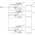
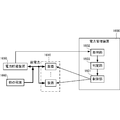
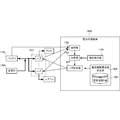
- the power management apparatus 1600 includes a control unit 1601, an acquisition unit 1602, and a determination unit 1603.
- the control unit 1601 controls a plurality of devices 1610 that receive distribution of the total power supplied from the power storage device 1650 and the other power source 1660.
- the acquisition unit 1602 acquires the remaining power amount of the power storage device 1650.
- the determination unit 1603 determines whether the remaining power amount of the power storage device 1650 is equal to or less than a first predetermined value.
- the control unit 1601 controls the plurality of devices 1610 so that the power from the other power sources 1660 is distributed to the power storage device 1650 when the remaining power amount of the power storage device 1650 is equal to or less than the first predetermined value.
- charging and discharging are switched according to the remaining power amount of the power storage device, so that when power is supplied to a plurality of devices, the power consumption of the plurality of devices is provided at a peak time.
- the amount of electricity stored in the power storage device can be secured.
- the power management apparatus 1700 includes a server control unit 1701, an acquisition unit 1702, a determination unit 1703, a threshold holding unit 1705, and a server priority determination unit 506.
- Server control unit 1701 controls a plurality of servers 1710 that receive distribution of the total power supplied from battery 1750 and power receiving unit 1760.
- Acquisition unit 1702 acquires the remaining power amount of battery 1750.
- the acquisition unit 1702 further acquires information such as an application executed in the server 1710 as the information processing apparatus.
- the determining unit 1703 refers to the threshold holding unit 1705 and determines whether or not the remaining power amount of the battery 1750 as the power storage device is equal to or less than a first predetermined value.
- the server control unit 1701 has a plurality of such that the power from the power receiving unit 1760 is distributed to the battery 1750 with priority over the plurality of servers 1710 when the remaining power amount of the battery 1750 is equal to or less than the first predetermined value. Control of the server 1710 is started. Specifically, in order to put the battery 1750 into the charging mode, the server control unit 1701 changes the server 1710 to the low power mode with low power consumption, and does not need the power of the battery 1750 (if there is surplus power) ), The battery 1750 is automatically charged. The server control unit 1701 may control the battery 1750 to switch on / off the power supply from the power receiving unit 1760 (dotted line arrow 1770 in FIG. 17).
- the determining unit 1703 refers to the threshold holding unit 1705 and determines whether or not the remaining power amount of the battery 1750 has exceeded a second predetermined value that is greater than the first predetermined value.
- the server control unit 1701 distributes the power from the power receiving unit 1760 with priority over the plurality of servers 1710 until the remaining power amount of the battery 1750 exceeds a second predetermined value that is greater than the first predetermined value.
- the plurality of servers 1710 are controlled as described above. That is, if the remaining power amount of the battery 1750 exceeds the second predetermined value, the server control unit 1701 is configured so that the power from the power receiving unit 1760 is distributed to the plurality of servers 1710 with priority over the battery 1750.
- a plurality of servers 1710 are controlled. The state of control of the plurality of servers 1710 can be confirmed on the console screen of the display unit provided in the server control unit 1701. Using the console screen, the user may perform ON / OFF of the battery charging priority function, server status display, server selection, alarm confirmation when the remaining battery level is low or power is over, and the like.
- the server control unit 1701 dynamically changes the second predetermined value based on the states of the plurality of servers 1710. In particular, the server control unit 1701 counts the number of servers 1710 in operation, and determines a second predetermined value according to the number. That is, when the number increases, the second predetermined value is increased. Alternatively, the server control unit 1701 may increase the second predetermined value when the calculation amount of the plurality of servers 1710 and the number of virtual devices (virtual machines) increase.
- the server control unit 1710 further distributes the power from the power receiving unit 1760 to the battery 1750 in preference to the server 1710, so that charging of the battery 1750 with a predetermined amount of power is completed within a predetermined time.
- a plurality of servers 1710 may be controlled.
- the server control unit 1701 reduces the power consumption of a predetermined server included in the plurality of servers 1710 so that power can be distributed to the battery 1750.
- the server 1710 can be driven in at least two drive modes including a high power mode (H mode) with high power consumption and a low power mode (L mode) with low power consumption.
- the server control unit 1701 determines the drive mode (H / L) for each of the plurality of servers. If it is necessary to reduce the power consumption of the server, the server 1710 is selectively driven in the L mode. Alternatively, the power consumption of the server may be reduced by changing the correspondence from the physical server to the virtual server.
- the server control unit 1701 selects the server 1710 based on the priority and reduces the power consumption.
- the server control unit 1701 selects the server 1710 in descending order of priority so that power can be distributed to the battery 1750, and reduces power consumption.
- the server priority is determined by the server priority determination unit 506 with reference to the server database 561.
- FIG. 7 is a table for explaining the contents of the server database 561 of the power management apparatus 1700 according to this embodiment.
- the server database 561 stores the maximum used power amount, the minimum used power amount, the required power amount, the priority of the running application, and the like acquired from each server 1710. Then, the server priority determination unit 506 determines the server priority according to the amount of power, the application, and the like, and sets the server priority in the server database 561. There are various methods for determining the priority. For example, an ID may be physically attached to the hardware of the server 1710, and the server cluster may be divided into No. 1, No. 2, and No. 3. The priority may be determined according to a fee (SLA: Service-level agreement) paid by the user of the server 1710.
- SLA Service-level agreement
- the priority may be logically determined by the type of OS (Operation System) or the type of executable application.
- the priority may be determined by self-reporting from the server 1710.
- the priority of the server may be determined according to whether the I / O load is large. In most servers, I / O is the bottleneck instead of the CPU (IO-bound), but if the I / O load is greater than the specified value, the CPU's drive mode is lowered to L However, the server output itself does not change much. Therefore, a method is also conceivable in which the I / O load is compared for each server, and the higher the I / O load, the lower the priority and the easier the L mode.
- the server control unit 1701 selects the server 1710 based on the priority of the application executed in each server 1710.
- the acquisition unit 1702 may acquire the actual power consumption in the server 1710.
- the server control unit 1701 may perform control so as to selectively reduce the power consumption of a plurality of servers 1710 having a large power consumption.
- the server control unit 1701 outputs an alarm when the remaining power amount of the battery 1750 is less than or equal to the third predetermined value and the power consumption amount of the plurality of servers 1710 is greater than or equal to the suppliable power amount of the power receiving unit 1760. Alternatively, the operations of the plurality of servers 1710 may be stopped.
- the determination unit 1703 may further determine whether the remaining power amount of the battery 1750 is greater than or equal to a fifth predetermined value that is greater than the first predetermined value.
- the server control unit 1701 may distribute the total power supplied from the battery 1750 and the power receiving unit 1760 to the plurality of servers 1710 when the remaining power amount of the battery 1750 is greater than or equal to a fifth predetermined value that is greater than a predetermined value.
- the server control unit 1701 supplies the power supplied from the power receiving unit 1760 to the plurality of servers 1710 without discharging or charging the battery 1750 when the remaining power amount of the battery 1750 is greater than or equal to a fifth predetermined value greater than a predetermined value. You may distribute.
- the server control unit 1701 selects a server having a high priority from the plurality of servers 1710 and increases the power consumption. Also good.
- the server control unit 1701 selects a server 1710 that has shifted to a mode in which the power consumption is small among the plurality of servers 1710, and May be increased.
- the present embodiment when power is supplied to a plurality of devices by switching between charging and discharging according to the remaining power amount of the battery, power is provided for peak power consumption of the plurality of devices.
- the amount of electricity stored in the storage device can be secured.
- the power management apparatus 100 includes a reception unit 101, a calculation unit 102, a first power value holding unit 103, a second power value holding unit 104, and a control unit 105.
- the receiving unit 101 receives, from each of the plurality of information processing apparatuses 110 and 120, power request information related to the requested power amount. Based on the power request information, the calculation unit 102 calculates the requested total power amount requested by the plurality of information processing apparatuses 110 and 120.
- the first power value holding unit 103 holds the first supplyable power value from the first power source 150 that can supply power to the plurality of information processing apparatuses 110 and 120.
- the second power value holding unit 104 holds the second suppliable power value from the second power source 160 that can supply power to the plurality of information processing apparatuses 110 and 120.
- the control unit 105 controls the plurality of information processing apparatuses 110 and 120 based on the requested total power amount, the first supplyable power value, and the second supplyable power value.
- the information processing apparatus since the information processing apparatus is controlled in consideration of the request of the information processing apparatus and the suppliable power, it is possible to supply power to a plurality of information processing apparatuses in consideration of balance.
- FIG. 2 is a block diagram showing a power-related configuration of a server system as an example of an information processing system including a power management apparatus.
- a power module 220 and a power management apparatus 200 are prepared for each region 251 that is a certain physical area.
- the power module 220 includes a power receiving unit 221 that receives system power from an electric power company and supplies the power to a server in the rack 250, and a battery 222 that accumulates power supplied from the power receiving unit 221.
- the battery 222 has different performance for each region 251, and has a maximum power storage amount corresponding to the power required in each region 251. If there is a surplus portion of the power supplied from the power receiving unit 221 to the region 251, it can be used to store the battery 222.
- the power management apparatus 200 monitors the power reception unit 221 and the battery 222 for each power module 220, and controls each server according to the power supply possible value thereof.
- the power management apparatus 200 is shown as a plurality of discrete configurations attached to the power module 220, but the present invention is not limited to this.
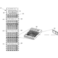
- FIG. 3 is a diagram illustrating a hardware configuration of the server system according to the present embodiment.
- the server system rack 250 includes a rack manager 301, a plurality of chassis 360, and a plurality of power modules 220.
- the rack manager 301 includes power management apparatuses 200 corresponding to the number of regions 251 and manages the power of the entire rack.
- the power module 220 is prepared for each region 251 and supplies power to a plurality of chassis 360 included in the region 251.
- the chassis 360 has a plurality of servers 361 built therein.
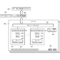
- FIG. 4A is a diagram showing a hardware configuration and a software configuration inside the chassis according to the present embodiment.
- the power management apparatus 200 is controlled by data center management software 450.
- the chassis 360 includes a network switch 401, a plurality of servers 361, a chassis management module 403, a fan 404, and a power source 405.
- Each server 361 includes a service processor 421 called BMC (Base board Management Controller) and a CPU 423 called SoC (System on Chip).
- BMC Basic board Management Controller
- SoC System on Chip
- the CPU 423 is a CPU LSI, which is not only a CPU core, but also SATA (Serial Advanced Technology Attachment) / SAS (Serial tta Attached Small Computer System Interface), PCIexpress (Peripheral Component Interconnect Express), Ethernet (registered trademark), etc. So, functions that are separate LSIs are also incorporated into the same chip.
- SATA Serial Advanced Technology Attachment
- SAS Serial tta Attached Small Computer System Interface
- PCIexpress Peripheral Component Interconnect Express
- Ethernet registered trademark
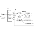
- FIG. 4B is a diagram showing the exchange of power-related information according to the present embodiment.
- the power management apparatus 200 receives an input power value (a value of external power used by the power module 220), a maximum input power value (a maximum value of external power that can be provided to the region), an output power value (depending on the power module) from the power module 220. Power value provided to the region), maximum output power value (total value of external power and battery supply power), battery remaining value (remaining power amount).
- the power management apparatus 200 receives power consumption in the chassis 360 or power consumption of each server from the chassis 360. Then, an H / L control instruction is sent to each server in the chassis 360.
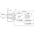
- FIG. 5 is a block diagram showing a functional configuration of the power management apparatus according to the present embodiment.
- the receiving unit 501 receives, from each of the plurality of servers 361, a demand 511 regarding the amount of power requested by each of the plurality of servers 361.
- the calculation unit 502 calculates the requested total power amount requested by the plurality of servers 361 based on the demand 511.
- the AC supply power holding unit 503 holds the AC power value supplied from the power receiving unit 221 that can supply power to a plurality of information processing apparatuses.
- the battery remaining amount holding unit 504 holds a battery remaining amount value in the battery 222 that can supply power to the plurality of servers 361.
- the server control unit 505 controls the plurality of servers 361 based on the demand 511, the AC power value, and the battery remaining amount value.
- the server 361 can be driven in at least two drive modes including a high power mode (H mode) with a high power consumption and a low power mode (L mode) with a low power consumption.
- the server control unit 505 determines a drive mode (H / L) 512 for each of the plurality of servers.
- the power management apparatus 200 includes a server priority determination unit 506 that determines priorities of the plurality of servers 361.
- the server priority determination unit 506 has a server database 561 that sets each attribute of the server 361 and the priority derived therefrom.
- the server control unit 505 determines whether to use the battery 222. If it is determined that the battery 222 is to be used, the server control unit 505 drives the plurality of servers 361 using both the power from the power reception unit 221 and the power from the battery 222.
- the server control unit 505 can drive the plurality of servers according to the priority (H) so that the plurality of servers 361 can be driven only by power from the power reception unit 221. / L) 512 is controlled.
- the server control unit 505 determines that the battery 222 is not used, the server with lower priority is compared with the server with higher priority so that the plurality of servers 361 can be driven only by the power from the power receiving unit 221. Control to drive in a mode with low power consumption. That is, a server with high priority is driven in the H mode, and a server with low priority is driven in the L mode. For example, when the remaining amount of the battery 222 is less than or equal to a predetermined value, the server control unit 505 determines that a server with a low priority is a server with a high priority so that a plurality of servers can be driven only with power from the power receiving unit 221. Control is performed so as to drive in a mode with less power consumption.
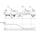
- FIG. 6 is a graph for explaining the function of the power management apparatus according to the present embodiment. For example, assuming that the maximum output power is 25 kW and the input power is 20 kW, first, when the remaining battery power is sufficient, charging is performed if the output power is Ckw or less, and if the output voltage exceeds 20 kW, Transition to the battery assist mode (a mode in which the battery 222 is used). On the other hand, when the remaining amount of power decreases due to the use of the battery 222 (for example, A% or less), it becomes impossible for a server other than a server with high priority to enter the battery assist mode, and the drive mode of some servers as necessary. Change to power saving mode.
- the battery assist mode is not permitted, and the server 361 is actively set in the low power mode to charge the battery 222.
- These threshold values A, B, and C can be set by the system operator.
- FIG. 7 is a table for explaining the contents of the server database 561 of the power management apparatus according to the present embodiment.
- the server database 561 stores, for example, the maximum power consumption, the minimum power consumption, the required power amount, and the priority of the running application received as the demand 511 from each server 361.
- the server priority determination unit 506 determines the server priority according to the amount of power or the application, and sets it in the server database 561.
- an ID may be physically attached to the hardware itself of the server 361, and the server cluster may be divided into No. 1, No. 2, and No. 3 in descending order of priority.
- the priority may be determined according to a fee (SLA: Service-level agreement) paid by the user of the server 361.
- SLA Service-level agreement
- the priority may be logically determined by the type of OS (Operation System) or the type of executable application.
- the priority may be determined by self-reporting from the server 361.
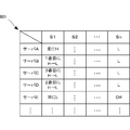
- FIG. 8 is a diagram showing a table showing detailed contents of priorities determined in the power management apparatus according to the present embodiment.
- the table 801 it is determined how each server 361 should be driven according to the situation (S1 to Sn) such as a time zone.
- the server A is always driven in the H mode, and the server E is always driven in the L mode.
- Server B to server D transition from the H mode to the L mode in the order of server B, server D, and server C in accordance with the supplied power value.
- the servers A to D are driven in the L mode, and the server E is set to Off (sleep).
- FIG. 9 is a diagram for explaining functions of the power management apparatus according to the present embodiment.
- FIG. 9 shows a table 900 showing an example of server drive control in each situation.
- the table 900 shows a server control method in ten situations S1 to S10 as an example.
- the vertical column 901 indicates the respective situation numbers, and the vertical column 902 schematically indicates the power that can be supplied (upper bar) and the drive mode (lower bar) of each server in each situation. Yes.
- the upper bar in the column 902 indicates the amount of system power (AC) and battery power (BATT) that can be output to the region 251 in each situation.
- the upper bar in the column 902 indicates the power consumption of the server 361 (in this example, only four), and the characters in the bar indicate the drive mode of each server 361. .
- the vertical column 903 indicates each situation by a mathematical expression, and the vertical column 904 indicates the state of the battery or the like.
- the situation S1 shows a situation where the total power consumption (required power) when all servers are driven in the H mode does not exceed the supply power value (AC) of the system power.
- AC supply power value
- the total power consumption when all servers are driven in the H mode exceeds the supply power value (AC) of the system power, but the maximum suppliable power value (AC + BATT) including the power of the battery 222 is set.
- the situation is not exceeded.
- the battery 222 may be discharged and fully assisted to drive all servers in the H mode.
- the process may move to the situation S3.
- Status S3 is a status where the battery 222 cannot be used or is not used. In this situation, until the power consumption of all the servers becomes equal to or less than the power supply value (AC) of the system power, the servers with lower priority are sequentially shifted to the L mode (pushing into AC). When the system power is left, the battery 222 is charged.
- AC power supply value
- the situation S4 shows a situation where the total power consumption when all servers are driven in the H mode exceeds the maximum suppliable power value (AC + BATT) obtained by adding the power of the battery 222 to the supply power value (AC) of the system power. Yes. In this case, even if the battery 222 is discharged and full assist is performed, all servers cannot be driven in the H mode.
- the servers with the lower priority are sequentially shifted to the L mode until the power consumption of all the servers becomes less than the maximum suppliable power value (AC + BATT) (AC + BATT). To the top).
- the process proceeds to situation S6.
- Status S6 is a status where the battery 222 cannot be used or is not used. In this situation, until the power consumption of all the servers becomes equal to or less than the power supply value (AC) of the system power, the servers with lower priority are sequentially shifted to the L mode (pushing into AC). When the system power is left, the battery 222 is charged.
- AC power supply value
- the total power consumption when all servers are driven in the L mode exceeds the supply power value (AC) of the grid power, but does not exceed the maximum suppliable power value (AC + BATT) including the power of the battery 222.
- AC supply power value
- AC + BATT maximum suppliable power value
- the battery 222 may be discharged and fully assisted to drive all servers in the L mode.
- the process may proceed to the situation S8.
- Status S8 is a status where the battery 222 cannot be used or is not used. In this situation, until the power consumption of all the servers becomes equal to or less than the power supply value (AC) of the system power, the servers with lower priority are sequentially shifted to the sleep mode (pushing into AC). At the same time, an alert indicating that the amount of power is insufficient is sent.
- AC power supply value
- Status S9 is a status where the grid power is down due to a power failure or maintenance. In this situation, if the total power consumption when all the servers are driven in the L mode does not exceed the suppliable power value of the battery 222, all the servers 361 are driven in the power saving mode to earn time, and an alert is issued. Call and wait for recovery from power outage.
- Status S10 is another status in which the grid power is down due to a power failure or maintenance.
- the server 361 having the lower priority is sequentially shifted to the sleep mode.
- an alert is sent to wait for recovery from a power outage.
- system power is shown on the left side and battery is shown on the right side, but the order may be reversed. . That is, the control using the grid power may be performed only when the battery is actively used and the supplied power value of the battery is lower than a certain value. In this case, the server drive mode is controlled to be pushed into the battery power value.
- FIG. 10 is a flowchart for explaining the flow of processing according to FIG. 9 in the power management apparatus according to the present embodiment.
- step S1001 the server control unit 505 determines whether or not the total required power value when all servers in the region are driven in the H mode is equal to or less than the supply power value AC of the system power. If the total required power value when all the servers are driven in the H mode is equal to or less than the supply power value AC of the system power, the process proceeds to step S1003, and the server control unit 505 sets all the servers in the high output mode (H mode). In step S1005, the battery is charged.
- step S1001 If it is determined in step S1001 that the total required power value when all servers in the region are driven in the H mode is larger than the supply power value AC of the system power (situation S2 in FIG. 9), the process proceeds to step S1007.
- step S1007 if the total value of the power supply value AC of the system power and the power supply value BATT of the battery 222 is smaller than the total value of the required power values when all the servers in the region are driven in the L mode (situation) S8), the process proceeds to step S1009.
- step S1009 the server control unit 505 transmits an alert, and further proceeds to step S1011.
- step S1011 the server control unit 505 determines the priority until the total value of the required power of all the servers in the region becomes smaller than the total value of the supply power value AC of the system power and the supply power value BATT of the battery 222.
- the server is shifted to sleep sequentially from the low server, and the process proceeds to step S1025.
- step S1007 if the total value of the grid power supply power value AC and the battery 222 supply power value BATT is greater than or equal to the total power value required when all servers in the region are driven in the L mode (situation) S5) Proceed to step S1013.
- step S1013 when the required power value when all the servers in the region are driven in the L mode is larger than the supply power value AC of the system power (situation S7), the process proceeds to step S1015.
- the server control unit 505 alerts that “use of the battery 222 is necessary to drive all servers” and proceeds to step S1017.
- step S1017 the server control unit 505 drives all servers in the L mode using the power of the battery 222 until it is determined in step S1007 that the power of the battery 222 is insufficient.
- step S1019 the server control unit 505 determines that the required power value when all servers are driven in the H mode is the sum of the grid power supply power value AC and the battery 222 supply power value BATT. Is also determined to be small.
- step S4 If the required power value when all servers are driven in the H mode is equal to or greater than the total value of the grid power supply power value AC and the battery 222 supply power value BATT (situation S4), the process proceeds to step S1021, and the server control unit A step 505 determines whether or not the battery 222 is used. When the battery is used, the process proceeds to step S1023, and the server control unit 505 gives priority until the required power value of all the servers is less than the total value of the supply power value AC of the system power and the supply power value BATT of the battery 222. The server is switched from the H mode to the L mode in order from a server with a low degree.
- step S1021 If it is determined in step S1021 that the battery 222 is not used, the process advances to step S1029, and the server control unit 505 prioritizes until the total required power value of all servers becomes equal to or less than the supply power value AC of the system power.
- the drive mode is switched in the order of H ⁇ L ⁇ sleep from a server with a low degree. Furthermore, it progresses to step S1031 and the server control part 505 performs charge, when the supply electric power value AC of system power is surplus.
- FIG. 11 is a diagram for explaining a functional configuration of the power management apparatus according to the present embodiment.
- the power management apparatus according to the present embodiment is different in that, instead of specifying the drive mode of the server, a budget related to power is notified to the server. Since other configurations and operations are the same as those of the second embodiment, the same configurations and operations are denoted by the same reference numerals, and detailed description thereof is omitted.
- FIG. 11 is a block diagram showing a functional configuration of the power management apparatus according to the present embodiment.
- the power management apparatus 1100 includes a server control unit 1105 that determines and notifies a budget (maximum usable power amount) 1112 of each server.
- Each server 1161 determines its own drive mode according to the budget 1112 received from the server control unit 1105.
- the server control unit 1105 calculates an upper limit value of the amount of power that can be used by each server in accordance with the priority for each server determined by the server priority determination unit 506. Then, the server control unit 1105 notifies the plurality of servers 1161 of the upper limit value of the electric energy that each of the plurality of servers 1161 can use.
- the server 1161 operates with an electric energy that is equal to or less than the notified upper limit value.
- FIG. 12 is a diagram showing exchange of power-related information according to the present embodiment. As illustrated in FIG. 12, the power management apparatus 1100 notifies the chassis 360 of the budget 1112.
- the server control unit 1105 determines the budget for each server, but may determine the budget for a plurality of servers (for example, servers in the chassis 360). In that case, a plurality of servers share the budget.
- the method of sharing may be, for example, a method in which a plurality of servers share a budget equally, or a method in which a high priority server secures a budget first and returns it when it is no longer needed.
- the server drive mode is determined according to the budget, it is possible to effectively and efficiently supply power to the server system using the system power and the battery. it can. That is, it is possible to realize a significantly smaller power consumption than the conventional average power consumption defined by the sum of the maximum power consumptions of all servers.
- FIG. 13 is a diagram for explaining functions of the power management apparatus according to the present embodiment.
- FIG. 13 shows a table 1300 showing an example of server drive control in each situation.
- server control methods in 12 situations S1 to S12 are shown as an example.
- a difference from the table 900 of FIG. 9 is that a situation S11 and a situation S12 are added. Since other contents are the same as those of the table 900, the same components and operations are denoted by the same reference numerals, and detailed description thereof is omitted.
- Status S11 indicates a status in which the total power consumption when all servers are driven in the H mode is less than the supply power value (AC) of the system power, but there is not enough room to charge the battery 222. In this case, the server drive request is completely satisfied, but the request to charge the battery 222 cannot be satisfied. Therefore, in the present embodiment, when there is a request to charge the battery 222 in this situation S11, the process shifts to a situation S12 in which some servers are driven in the L mode.
- a request to charge the battery 222 may be a case where the remaining power value of the battery 222 is lower than a predetermined value.
- FIG. 14 is a flowchart for explaining the flow of processing according to FIG. 13 in the power management apparatus according to the present embodiment.
- the difference from the flowchart of FIG. 10 is that steps S1401 to S1409 are added. Since other contents are the same as those in the flowchart of FIG. 10, the same components and operations are denoted by the same reference numerals, and detailed description thereof is omitted.
- step S1001 the server control unit 505 determines whether or not the total required power value when all servers in the region are driven in the H mode is equal to or less than the supply power value AC of the system power. If the total required power value when all the servers are driven in the H mode is equal to or less than the supply power value AC of the system power, the process proceeds to step S1401 and the server control unit 505 determines whether there is a charge request. If there is a charge request, the process proceeds to step S1403.
- step S1403 the server control unit 505 determines that the power consumption of all servers is equal to or less than C in FIG. 6 (the value obtained by subtracting the power required for charging from the maximum output power of the system power) until there is a charge margin. Until it becomes, the drive mode of the low priority server is switched. Specifically, the determination of whether there is a charge margin is repeated while sequentially switching the server drive mode from the H mode to the L mode. If there is a charge margin, the server is controlled in the drive mode at that time. Even if all are driven in the L mode, if there is no charge margin, the determination as to whether or not there is a charge margin is repeated while sequentially switching to the sleep mode from the server with the lower priority. If there is a charge margin, the process proceeds to step S1405 and the battery 222 is charged.
- C in FIG. 6 the value obtained by subtracting the power required for charging from the maximum output power of the system power
- step S1401 If it is determined in step S1401 that there is no charge request, the process proceeds to step S1407, and the server control unit 505 drives all servers in the H mode, and performs charging if there is a charge margin in step S1409 (if there is no charge margin). Do not charge).
- the setting as to whether or not to prioritize battery charging may be received in advance via the control screen of the power management apparatus as shown in FIG. In that case, if the setting is such that battery charging is prioritized, it may be determined in step S1401 that there is a charging request.
- the server control unit 505 may determine whether or not there is a charge request according to the remaining power value of the battery 222. That is, when the remaining power value of the battery 222 is smaller than the predetermined value, it is determined that the request for charging the battery 222 is strong, and the server control unit 505 prioritizes the charging of the battery 222 over the drive of the server. For example, the server control unit 505 determines the remaining power value to be secured in the battery 222 according to the minimum power value required for driving all servers in the L mode and the time estimated to be required for recovery from the power failure ( The “predetermined value”) may be determined.
- the server can be driven while placing importance on the amount of electricity stored in the battery by operating the server in the L mode in order to prioritize the charging of the battery.
- a server has been described as an example of an information processing apparatus as an object to which power is supplied.
- the present invention is not limited to this, and storage devices, network devices, PCs (Personal Computer), TV, air conditioner, and other electrical appliances such as home appliances may be controlled.
- FIG. 18 when supplying electric power from a battery 1750 and a power receiving unit 1760 to an electric device, a configuration in which electric power is distributed to each electric device via a plurality of hubs 1810 can be considered.
- the hub 1810 can perform various types of switching of power supply, and on / off for a television, temperature adjustment for an air conditioner and refrigerator, and brightness adjustment for lighting.
- the hub control unit 1801 is based on the remaining power amount of the battery 1750, the predetermined threshold, and the priority determined by the electrical device priority determination unit 1806 with reference to the electrical device database 1861. Controls each hub 1810.
- the system power source and the battery have been described as the power supply source.
- the present invention is not limited to this, and there may be two power sources.
- the information processing apparatus may be controlled based on power from two power sources, a fossil fuel system power source and a renewable energy system power source.
- the drive mode of the information processing apparatus may be controlled in accordance with the power values from three or more types of power sources.
- the H mode, the L mode, and the sleep have been described as examples of the server drive mode, other modes (for example, an M mode with power consumption between the H mode and the L mode) may be included.
- the present invention may be applied to a system composed of a plurality of devices, or may be applied to a single device. Furthermore, the present invention can also be applied to a case where an information processing program that implements the functions of the embodiments is supplied directly or remotely to a system or apparatus. Therefore, in order to realize the functions of the present invention on a computer, a program installed on the computer, a medium storing the program, and a WWW (World Wide Web) server that downloads the program are also included in the scope of the present invention. . In particular, at least a non-transitory computer-readable medium that stores a program that causes a computer to execute the processing steps included in the above-described embodiments is included in the scope of the present invention.
- Receiving means for receiving, from each of the plurality of information processing devices, power request information regarding the amount of power requested by each of the plurality of information processing devices; Calculation means for calculating a total requested power amount requested by the plurality of information processing devices based on the power request information; First power value holding means for holding a first supplyable power value from a first power source capable of supplying power to the plurality of information processing devices; Second power value holding means for holding a second suppliable power value from a second power source capable of supplying power to the plurality of information processing devices; Control means for controlling the plurality of information processing devices based on the requested total power amount, the first supplyable power value, and the second supplyable power value; Power management device with (Appendix 2) Each of the plurality of information processing devices can be driven in at least two drive modes including a high power mode with high power consumption and a low
- the control unit notifies the plurality of information processing devices of an upper limit value of the amount of power that can be used by each of the plurality of information processing devices, and causes the control to be performed with a power amount equal to or less than the upper limit value.
- the power management device described in 1. (Appendix 4)
- the first power source is a grid power source;
- the second power source is a battery;
- the power management apparatus according to appendix 1, wherein the second power value holding unit is a unit that monitors a remaining amount of battery power that can be supplied to the plurality of information processing apparatuses.
- the control means includes If the requested total power amount is smaller than the total power value of the first suppliable power value and the second suppliable power value, determine whether to use the second power source; When it is determined that the second power source is used, the plurality of information processing devices are driven using both the power from the first power source and the power from the second power source, The power management apparatus according to supplementary note 1, wherein when it is determined that the second power source is not used, the plurality of information processing apparatuses are controlled according to the priority.
- control means If the control means determines that the second power source is not used, the control means can drive the plurality of information processing devices only with power from the first power source according to the priority.
- Appendix 7) The power management apparatus according to appendix 6, wherein the control means controls the information processing apparatus with the lower priority to be driven in a mode with less power consumption than the information processing apparatus with the higher priority.
- the first power source is a grid power source;
- the second power source is a battery;
- the control means allows the information processing device with a low priority to drive the plurality of information processing devices only with power from the grid power source.
- the power management apparatus according to any one of appendices 5 to 7, wherein the power management apparatus is controlled so as to be driven in a mode with less power consumption than an information processing apparatus having a high priority.
- the first power source is a grid power source;
- the second power source is a battery;
- the control means determines that the battery is not to be used and the remaining power amount of the battery is equal to or less than a predetermined value, the information processing apparatus having a low priority is configured to charge the battery.
- the power management apparatus according to any one of appendices 5 to 8, wherein the power management apparatus is controlled so as to be driven in a mode that consumes less power than a high-performance information processing apparatus.
- (Appendix 12) A plurality of information processing devices; Receiving means for receiving, from each of the plurality of information processing devices, power request information relating to the amount of power requested by each of the plurality of information processing devices; Calculation means for calculating a total requested power amount requested by the plurality of information processing devices based on the power request information; First power value holding means for holding a first supplyable power value from a first power source capable of supplying power to the plurality of information processing devices; Second power value holding means for holding a second suppliable power value from a second power source capable of supplying power to the plurality of information processing devices; Control means for controlling the plurality of information processing devices based on the requested total power amount, the first supplyable power value, and the second supplyable power value; Information processing system with
Landscapes
- Engineering & Computer Science (AREA)
- Power Engineering (AREA)
- Physics & Mathematics (AREA)
- General Physics & Mathematics (AREA)
- Theoretical Computer Science (AREA)
- Automation & Control Theory (AREA)
- General Engineering & Computer Science (AREA)
- Electromagnetism (AREA)
- Radar, Positioning & Navigation (AREA)
- Charge And Discharge Circuits For Batteries Or The Like (AREA)
- Supply And Distribution Of Alternating Current (AREA)
Abstract
Description
電力貯蔵装置および他の電源から供給される総電力の分配を受ける複数の装置を制御する制御手段と、
前記電力貯蔵装置の残電力量を取得する取得手段と、
前記電力貯蔵装置の前記残電力量が第1所定値以下か否かを判定する判定手段と、
を備え、
前記制御手段は、前記電力貯蔵装置の前記残電力量が第1所定値以下の場合に、前記他の電源からの電力が前記電力貯蔵装置に分配されるように、前記複数の装置を制御する。
複数の装置と電力貯蔵装置および他の電源を含むシステムの電力管理方法であって、
前記電力貯蔵装置の残電力量を取得する取得ステップと、
前記電力貯蔵装置の前記残電力量が第1所定値以下か否かを判定する判定ステップと、
前記電力貯蔵装置の前記残電力量が第1所定値以下の場合に、前記他の電源からの電力が前記電力貯蔵装置に分配されるように、前記複数の装置を制御する制御ステップと、
を含む。
複数の装置と電力貯蔵装置および他の電源を含むシステムの電力を管理するプログラムであって、
前記電力貯蔵装置の残電力量を取得する取得ステップと、
前記電力貯蔵装置の前記残電力量が第1所定値以下か否かを判定する判定ステップと、
前記電力貯蔵装置の前記残電力量が第1所定値以下の場合に、前記他の電源からの電力が前記電力貯蔵装置に分配されるように、前記複数の装置を制御する制御ステップと、
をコンピュータに実行させる。
複数の装置に電力を供給する電力貯蔵装置および他の電源を含むシステムであって、
前記電力貯蔵装置の残電力量を取得する取得手段と、
前記電力貯蔵装置の前記残電力量が第1所定値以下か否かを判定する判定手段と、
前記電力貯蔵装置の前記残電力量が第1所定値以下の場合に、前記他の電源からの電力が前記電力貯蔵装置に分配されるように、前記複数の装置を制御する制御手段と、
を備えた。
本発明の第1実施形態としての電力管理装置1600について、図16を用いて説明する。電力管理装置1600は、制御部1601、取得部1602、および判定部1603を含む。
本発明の第2実施形態としての電力管理装置1700について、図17を用いて説明する。電力管理装置1700は、サーバ制御部1701、取得部1702、及び判定部1703、閾値保持部1705、サーバ優先度決定部506を含む。サーバ制御部1701は、バッテリ1750および受電部1760から供給される総電力の分配を受ける複数のサーバ1710を制御する。取得部1702は、バッテリ1750の残電力量を取得する。取得部1702は、さらに、情報処理装置としてのサーバ1710において実行されるアプリケーションなどの情報を取得する。
本発明の第3実施形態としての電力管理装置100について、図1を用いて説明する。電力管理装置100は、受信部101、算出部102、第1電力値保持部103、第2電力値保持部104、および制御部105を含む。
次に本発明の第4実施形態に係る電力管理装置について、図2~図10を用いて説明する。図2は電力管理装置を備えた情報処理システムの一例としてのサーバシステムの電力関連構成を示すブロック図である。
512を制御する。
次に本発明の第5実施形態に係る電力管理装置について、図11および図12を用いて説明する。図11は、本実施形態に係る電力管理装置の機能構成を説明するための図である。本実施形態に係る電力管理装置は、上記第2実施形態と比べると、サーバの駆動モードを指定する代わりに、電力に関するバジェットをサーバに通知する点で異なる。その他の構成および動作は、第2実施形態と同様であるため、同じ構成および動作については同じ符号を付してその詳しい説明を省略する。
次に本発明の第6実施形態に係る電力管理装置について、図13および図14を用いて説明する。図13は、本実施形態に係る電力管理装置の機能を説明するための図である。図13には、各状況におけるサーバの駆動制御例を示すテーブル1300が示されている。テーブル1300においては、例として12個の状況S1~S12においてのサーバ制御方法を示している。図9のテーブル900と異なる点は、状況S11と状況S12が加えられている点である。他の内容は、テーブル900と同様であるため、同じ構成および動作については同じ符号を付してその詳しい説明を省略する。
なお、上記第2乃至第6実施形態では、電力を供給する対象としての情報処理装置の一例としてサーバについて説明したが、本発明はこれに限定されるものではなく、ストレージ機器、ネットワーク機器、PC(Personal Computer)、テレビ、エアコン、その他の家電などの電気機器を制御する構成でもよい。例えば、図18に示すように、電気機器に対してバッテリ1750および受電部1760からの電力を供給する際、複数のハブ1810を介して各電気機器に電力を分配する構成が考えられる。ハブ1810は、電力供給の各種スイッチングを行なうことができ、テレビであればオン/オフ、エアコンおよび冷蔵庫であれば温度調整、照明であれば明るさ調整を行なう。この場合も、第2実施形態と同様に、バッテリ1750の残電力量および所定の閾値および電気機器優先度決定部1806が電気機器データベース1861を参照に決定した優先度に基づいて、ハブ制御部1801が各ハブ1810を制御する。
上記の実施形態の一部または全部は、以下の付記のようにも記載されうるが、以下には限られない。
(付記1)
複数の情報処理装置の各々から、前記複数の情報処理装置の各々が要求する電力量に関する電力要求情報を受信する受信手段と、
前記電力要求情報に基づいて、前記複数の情報処理装置が要求する要求総電力量を算出する算出手段と、
前記複数の情報処理装置に対して電力を供給可能な第1電力源からの第1供給可能電力値を保持する第1電力値保持手段と、
前記複数の情報処理装置に対して電力を供給可能な第2電力源からの第2供給可能電力値を保持する第2電力値保持手段と、
前記要求総電力量と前記第1供給可能電力値と前記第2供給可能電力値とに基づいて、前記複数の情報処理装置を制御する制御手段と、
を備えた電力管理装置。
(付記2)
前記複数の情報処理装置のそれぞれは、電力消費量の多い高電力モードと電力消費量の少ない低電力モードを含む少なくとも2つの駆動モードで駆動可能であり、
前記制御手段は、前記複数の情報処理装置のそれぞれにおける前記駆動モードを決定する付記1に記載の電力管理装置。
(付記3)
前記制御手段は、前記複数の情報処理装置のそれぞれが使用可能な電力量の上限値を、前記複数の情報処理装置に対して通知し、前記上限値以下の電力量で制御させる付記1または2に記載の電力管理装置。
(付記4)
前記第1電力源は系統電力源であり、
前記第2電力源はバッテリであって、
前記第2電力値保持手段は、前記複数の情報処理装置に対して供給可能なバッテリの残電力量を監視する手段である付記1の電力管理装置。
(付記5)
前記複数の情報処理装置の優先度を設定する設定手段をさらに備え、
前記制御手段は、
前記要求総電力量が、前記第1供給可能電力値と前記第2供給可能電力値との合計電力値よりも小さい場合、前記第2電力源を使用するか否かを判定し、
前記第2電力源を使用すると判定した場合には、前記第1電力源からの電力と前記第2電力源からの電力との両方を用いて、前記複数の情報処理装置を駆動し、
前記第2電力源を使用しないと判定した場合には、前記優先度に応じて、前記複数の情報処理装置を制御する付記1に記載の電力管理装置。
(付記6)
前記制御手段は、前記第2電力源を使用しないと判定した場合には、前記第1電力源からの電力のみで前記複数の情報処理装置を駆動できるように、前記優先度に応じて、前記複数の情報処理装置を制御する付記5に記載の電力管理装置。
(付記7)
前記制御手段は、前記優先度の低い情報処理装置が前記優先度の高い情報処理装置に比べて電力消費量の少ないモードで駆動するように制御する付記6に記載の電力管理装置。
(付記8)
前記第1電力源は系統電力源であり、
前記第2電力源はバッテリであって、
前記制御手段は、前記バッテリの残電力量が所定値以下の場合に、前記系統電力源からの電力のみで前記複数の情報処理装置を駆動できるように、前記優先度の低い情報処理装置が前記優先度の高い情報処理装置に比べて電力消費量の少ないモードで駆動するように制御する付記5乃至7のいずれか1項に記載の電力管理装置。
(付記9)
前記第1電力源は系統電力源であり、
前記第2電力源はバッテリであって、
前記制御手段は、前記バッテリを使用しないと判定した場合であって前記バッテリの残電力量が所定値以下の場合に、前記バッテリを充電できるように、前記優先度の低い情報処理装置が前記優先度の高い情報処理装置に比べて電力消費量の少ないモードで駆動するように制御する付記5乃至8のいずれか1項に記載の電力管理装置。
(付記10)
複数の情報処理装置の各々から、前記複数の情報処理装置の各々が要求する電力量に関する電力要求情報を受信する受信ステップと、
前記電力要求情報に基づいて、前記複数の情報処理装置が要求する要求総電力量を算出する算出ステップと、
前記複数の情報処理装置に対して電力を供給可能な第1電力源からの第1供給可能電力値と、前記複数の情報処理装置に対して電力を供給可能な第2電力源からの第2供給可能電力値と、前記要求総電力量とに基づいて、前記複数の情報処理装置を制御する制御ステップと、
を含む電力管理方法。
(付記11)
複数の情報処理装置の各々から、前記複数の情報処理装置の各々が要求する電力量に関する電力要求情報を受信する受信ステップと、
前記電力要求情報に基づいて、前記複数の情報処理装置が要求する要求総電力量を算出する算出ステップと、
前記複数の情報処理装置に対して電力を供給可能な第1電力源からの第1供給可能電力値と、前記複数の情報処理装置に対して電力を供給可能な第2電力源からの第2供給可能電力値と、前記要求総電力量とに基づいて、前記複数の情報処理装置を制御する制御ステップと、
をコンピュータに実行させる電力管理プログラム。
(付記12)
複数の情報処理装置と、
前記複数の情報処理装置の各々から、前記複数の情報処理装置の各々が要求する電力量に関する電力要求情報を受信する受信手段と、
前記電力要求情報に基づいて、前記複数の情報処理装置が要求する要求総電力量を算出する算出手段と、
前記複数の情報処理装置に対して電力を供給可能な第1電力源からの第1供給可能電力値を保持する第1電力値保持手段と、
前記複数の情報処理装置に対して電力を供給可能な第2電力源からの第2供給可能電力値を保持する第2電力値保持手段と、
前記要求総電力量と前記第1供給可能電力値と前記第2供給可能電力値とに基づいて、前記複数の情報処理装置を制御する制御手段と、
を備えた情報処理システム。
Claims (21)
- 電力貯蔵装置および他の電源から供給される総電力の分配を受ける複数の装置を制御する制御手段と、
前記電力貯蔵装置の残電力量を取得する取得手段と、
前記電力貯蔵装置の前記残電力量が第1所定値以下か否かを判定する判定手段と、
を備え、
前記制御手段は、前記電力貯蔵装置の前記残電力量が第1所定値以下の場合に、前記他の電源からの電力が前記電力貯蔵装置に分配されるように、前記複数の装置を制御する電力管理装置。 - 前記制御手段は、前記電力貯蔵装置の前記残電力量が前記第1所定値以下の場合に、前記他の電源からの電力が、前記電力貯蔵装置に対して、前記複数の装置より優先して分配されるように、前記複数の装置を制御する請求項1に記載の電力管理装置。
- 前記制御手段は、前記電力貯蔵装置の残電力量が前記第1所定値より大きい第2所定値を超えるまで、前記他の電源からの電力が、前記電力貯蔵装置に対して、前記複数の装置より優先して分配されるように、前記複数の装置を制御する請求項2に記載の電力管理装置。
- 前記制御手段は、前記他の電源からの電力が、前記電力貯蔵装置に対して、前記複数の装置より優先して分配されることにより、所定時間内に前記電力貯蔵装置への所定電力量の充電が完了するように、前記複数の装置を制御する請求項2に記載の電力管理装置。
- 前記制御手段は、前記電力貯蔵装置へ電力の分配が可能となるように、前記複数の装置に含まれる所定の装置の電力消費量を減少させる請求項1乃至4のいずれか1項に記載の電力管理装置。
- 前記制御手段は、前記複数の装置から、優先度に基づいて一部の装置を選択し、電力消費量を減少させる請求項5に記載の電力管理装置。
- 前記制御手段は、前記電力貯蔵装置へ電力の分配が可能となるように、前記複数の装置から、優先度の低い順に一部の装置を選択し、電力消費量を減少させる請求項5または6に記載の電力管理装置。
- 前記制御手段は、前記複数の装置において実行されるアプリケーションの優先度に基づいて装置を選択する請求項3乃至7のいずれか1項に記載の電力管理装置。
- 前記制御手段は、他の装置よりも電力消費量が大きいモードで動作している装置を、優先的に、電力消費量が小さいモードに移行させることで電力消費量を減少させる請求項1乃至9のいずれか1項に記載の電力管理装置。
- 前記制御手段は、前記第2所定値を前記複数の装置の状態に基づいて動的に変更させる請求項3に記載の電力管理装置。
- 前記制御手段は、稼働中の装置の台数が増加した場合に、前記第2所定値を増加させる請求項10に記載の電力管理装置。
- 前記制御手段は、前記複数の装置の演算量が増加した場合に前記第2所定値を増加させる請求項10に記載の電力管理装置。
- 前記制御手段は、前記電力貯蔵装置の残電力量が第3所定値以下の場合であって、前記複数の装置の電力消費量が前記他の電源の供給可能電力量以上の場合に、アラームを出力または前記複数の装置を停止する請求項1乃至12のいずれか1項に記載の電力管理装置。
- 前記判定手段が、前記電力貯蔵装置の残電力量が前記第1所定値より大きい前記第5所定値以上だと判定した場合に、
前記制御手段は、前記電力貯蔵装置および前記他の電源から供給される総電力を前記複数の装置に分配する請求項1乃至13のいずれか1項に記載の電力管理装置。 - 前記判定手段が、前記電力貯蔵装置の残電力量が前記第1所定値より大きい前記第5所定値以上だと判定した場合に、
前記制御手段は、前記電力貯蔵装置を充電も放電もせずに、前記他の電源から供給される電力を前記複数の装置に分配する請求項1乃至13のいずれか1項に記載の電力管理装置。 - 前記判定手段が、前記電力貯蔵装置の残電力量は前記第5所定値以上だと判定した場合に、
前記制御手段は、前記複数の装置から、優先度の高い装置を選択し、電力消費量を増加させる請求項14または15に記載の電力管理装置。 - 前記判定手段が、前記電力貯蔵装置の残電力量は前記第5所定値以上だと判定した場合に、
前記制御手段は、前記複数の装置において、電力消費量が小さいモードに移行している装置を選択し、電力消費量を増加させる請求項14または15に記載の電力管理装置。 - 前記複数の装置は、情報処理装置である請求項1乃至17のいずれか1項に記載の電力管理装置。
- 複数の装置と電力貯蔵装置および他の電源を含むシステムの電力管理方法であって、
前記電力貯蔵装置の残電力量を取得する取得ステップと、
前記電力貯蔵装置の前記残電力量が第1所定値以下か否かを判定する判定ステップと、
前記電力貯蔵装置の前記残電力量が第1所定値以下の場合に、前記他の電源からの電力が前記電力貯蔵装置に分配されるように、前記複数の装置を制御する制御ステップと、
を含む電力管理方法。 - 複数の装置と電力貯蔵装置および他の電源を含むシステムの電力を管理するプログラムであって、
前記電力貯蔵装置の残電力量を取得する取得ステップと、
前記電力貯蔵装置の前記残電力量が第1所定値以下か否かを判定する判定ステップと、
前記電力貯蔵装置の前記残電力量が第1所定値以下の場合に、前記他の電源からの電力が前記電力貯蔵装置に分配されるように、前記複数の装置を制御する制御ステップと、
をコンピュータに実行させる電力管理プログラム。 - 複数の装置に電力を供給する電力貯蔵装置および他の電源を含むシステムであって、
前記電力貯蔵装置の残電力量を取得する取得手段と、
前記電力貯蔵装置の前記残電力量が第1所定値以下か否かを判定する判定手段と、
前記電力貯蔵装置の前記残電力量が第1所定値以下の場合に、前記他の電源からの電力が前記電力貯蔵装置に分配されるように、前記複数の装置を制御する制御手段と、
を備えた電力供給システム。
Priority Applications (4)
| Application Number | Priority Date | Filing Date | Title |
|---|---|---|---|
| CN201480032087.9A CN105264739A (zh) | 2013-06-04 | 2014-05-30 | 电力供应系统、电力管理装置、电力管理方法和电力管理程序 |
| US14/895,812 US10146241B2 (en) | 2013-06-04 | 2014-05-30 | Power supply system, power management apparatus, power management method, and power management program |
| DE112014002369.8T DE112014002369T5 (de) | 2013-06-04 | 2014-05-30 | Energieversorgungssystem, Energieverwaltungsvorrichtung, Energieverwaltungsverfahren und Energieverwaltungsprogramm |
| US16/172,597 US10466729B2 (en) | 2013-06-04 | 2018-10-26 | Power supply system, power management, apparatus, power management method, and power management program |
Applications Claiming Priority (4)
| Application Number | Priority Date | Filing Date | Title |
|---|---|---|---|
| JP2013118361 | 2013-06-04 | ||
| JP2013-118361 | 2013-06-04 | ||
| JP2013-237304 | 2013-11-15 | ||
| JP2013237304A JP5835304B2 (ja) | 2013-06-04 | 2013-11-15 | 電力供給システム、電力管理装置、電力管理方法および電力管理プログラム |
Related Child Applications (2)
| Application Number | Title | Priority Date | Filing Date |
|---|---|---|---|
| US14/895,812 A-371-Of-International US10146241B2 (en) | 2013-06-04 | 2014-05-30 | Power supply system, power management apparatus, power management method, and power management program |
| US16/172,597 Continuation US10466729B2 (en) | 2013-06-04 | 2018-10-26 | Power supply system, power management, apparatus, power management method, and power management program |
Publications (1)
| Publication Number | Publication Date |
|---|---|
| WO2014196472A1 true WO2014196472A1 (ja) | 2014-12-11 |
Family
ID=52008117
Family Applications (1)
| Application Number | Title | Priority Date | Filing Date |
|---|---|---|---|
| PCT/JP2014/064449 Ceased WO2014196472A1 (ja) | 2013-06-04 | 2014-05-30 | 電力供給システム、電力管理装置、電力管理方法および電力管理プログラム |
Country Status (5)
| Country | Link |
|---|---|
| US (2) | US10146241B2 (ja) |
| JP (1) | JP5835304B2 (ja) |
| CN (1) | CN105264739A (ja) |
| DE (1) | DE112014002369T5 (ja) |
| WO (1) | WO2014196472A1 (ja) |
Families Citing this family (10)
| Publication number | Priority date | Publication date | Assignee | Title |
|---|---|---|---|---|
| JP5835304B2 (ja) * | 2013-06-04 | 2015-12-24 | 日本電気株式会社 | 電力供給システム、電力管理装置、電力管理方法および電力管理プログラム |
| CN106960985B (zh) * | 2016-01-08 | 2019-10-15 | 松下知识产权经营株式会社 | 服务器装置的控制方法和服务器装置 |
| KR101936995B1 (ko) * | 2016-11-25 | 2019-01-10 | 현대자동차주식회사 | 모터 제어 방법 및 시스템 |
| US11043800B2 (en) | 2017-09-29 | 2021-06-22 | Hewlett Packard Enterprise Development Lp | Energy storage components to power loads during transitions between power supplies |
| JP2019154210A (ja) * | 2018-03-06 | 2019-09-12 | キヤノン株式会社 | 電子機器およびその制御方法並びにプログラム |
| CN109409727A (zh) * | 2018-10-19 | 2019-03-01 | 珠海格力电器股份有限公司 | 一种电量分配方法及装置 |
| CN112448429B (zh) * | 2019-08-30 | 2022-11-04 | Oppo广东移动通信有限公司 | 一种控制方法、终端及计算机存储介质 |
| KR102916537B1 (ko) * | 2019-12-11 | 2026-01-22 | 에스케이하이닉스 주식회사 | 시스템, 컨트롤러 및 시스템의 동작 방법 |
| JP2023030899A (ja) * | 2021-08-24 | 2023-03-08 | 富士通株式会社 | 管理プログラム、管理装置及び管理方法 |
| US12086428B2 (en) * | 2021-11-15 | 2024-09-10 | Samsung Electronics Co., Ltd. | Memory controller adjusting power, memory system including same, and operating method for memory system |
Citations (3)
| Publication number | Priority date | Publication date | Assignee | Title |
|---|---|---|---|---|
| JP2008067439A (ja) * | 2006-09-05 | 2008-03-21 | Nippon Telegr & Teleph Corp <Ntt> | 電力供給方法およびシステム |
| JP2008306832A (ja) * | 2007-06-07 | 2008-12-18 | Kansai Electric Power Co Inc:The | 電力貯蔵システム |
| JP2011223786A (ja) * | 2010-04-13 | 2011-11-04 | Nec Corp | 電気機器 |
Family Cites Families (19)
| Publication number | Priority date | Publication date | Assignee | Title |
|---|---|---|---|---|
| JPH05159885A (ja) | 1991-04-30 | 1993-06-25 | Mitsubishi Plastics Ind Ltd | 太陽電池利用の照明装置 |
| US6498460B1 (en) * | 2001-12-14 | 2002-12-24 | Compaq Information Technologies Group, L.P. | Prioritization-based power management protocol in a computer system |
| JP2005083195A (ja) | 2003-09-04 | 2005-03-31 | Honda Motor Co Ltd | 電源装置 |
| JP2006158146A (ja) | 2004-12-01 | 2006-06-15 | Toko Electric Corp | 電力用供給管理システム |
| US8266456B2 (en) * | 2007-10-15 | 2012-09-11 | Apple Inc. | Supplying remaining available current to port in excess of bus standard limit |
| JP2009124792A (ja) | 2007-11-12 | 2009-06-04 | Osaka Gas Co Ltd | 電力供給システム |
| JP5391886B2 (ja) | 2009-07-10 | 2014-01-15 | パナソニック株式会社 | 充電手段付き電気機器、充電手段付き電気機器の制御方法、およびそのプログラム |
| EP2463981A4 (en) | 2009-08-04 | 2017-09-20 | Nec Corporation | Energy system |
| US8951968B2 (en) | 2009-10-05 | 2015-02-10 | Northwestern University | Methods of treating depression and other related diseases |
| US20120235493A1 (en) | 2009-11-30 | 2012-09-20 | Kyocera Corporation | Control device, control system, and control method |
| US8332666B2 (en) * | 2009-12-07 | 2012-12-11 | International Business Machines Corporation | Power management method and system |
| KR101174891B1 (ko) * | 2010-06-01 | 2012-08-17 | 삼성에스디아이 주식회사 | 전력 저장 시스템 및 그 제어방법 |
| JP2012010458A (ja) | 2010-06-23 | 2012-01-12 | Toshiba Tec Corp | 電源制御装置、電子機器及びプログラム |
| JP5300829B2 (ja) | 2010-11-30 | 2013-09-25 | 三菱電機株式会社 | 住宅電気エネルギー管理装置、住宅電気エネルギー管理システム、住宅電気エネルギー管理方法、および、プログラム |
| JP5845066B2 (ja) | 2011-11-16 | 2016-01-20 | トヨタホーム株式会社 | 電力供給システム |
| US8984307B2 (en) * | 2012-05-21 | 2015-03-17 | Qualcomm Incorporated | System and method for dynamic battery current load management in a portable computing device |
| US9502893B2 (en) * | 2012-09-20 | 2016-11-22 | Nova Greentech, Inc. | Distributed power supply system and method |
| JP5835304B2 (ja) * | 2013-06-04 | 2015-12-24 | 日本電気株式会社 | 電力供給システム、電力管理装置、電力管理方法および電力管理プログラム |
| JP5928908B2 (ja) * | 2013-09-30 | 2016-06-01 | カシオ計算機株式会社 | 電子機器、給電制御方法、及びプログラム |
-
2013
- 2013-11-15 JP JP2013237304A patent/JP5835304B2/ja not_active Expired - Fee Related
-
2014
- 2014-05-30 WO PCT/JP2014/064449 patent/WO2014196472A1/ja not_active Ceased
- 2014-05-30 US US14/895,812 patent/US10146241B2/en active Active
- 2014-05-30 CN CN201480032087.9A patent/CN105264739A/zh active Pending
- 2014-05-30 DE DE112014002369.8T patent/DE112014002369T5/de not_active Withdrawn
-
2018
- 2018-10-26 US US16/172,597 patent/US10466729B2/en active Active
Patent Citations (3)
| Publication number | Priority date | Publication date | Assignee | Title |
|---|---|---|---|---|
| JP2008067439A (ja) * | 2006-09-05 | 2008-03-21 | Nippon Telegr & Teleph Corp <Ntt> | 電力供給方法およびシステム |
| JP2008306832A (ja) * | 2007-06-07 | 2008-12-18 | Kansai Electric Power Co Inc:The | 電力貯蔵システム |
| JP2011223786A (ja) * | 2010-04-13 | 2011-11-04 | Nec Corp | 電気機器 |
Also Published As
| Publication number | Publication date |
|---|---|
| DE112014002369T5 (de) | 2016-01-28 |
| US20160116932A1 (en) | 2016-04-28 |
| JP2015015877A (ja) | 2015-01-22 |
| US10466729B2 (en) | 2019-11-05 |
| JP5835304B2 (ja) | 2015-12-24 |
| US10146241B2 (en) | 2018-12-04 |
| US20190064865A1 (en) | 2019-02-28 |
| CN105264739A (zh) | 2016-01-20 |
Similar Documents
| Publication | Publication Date | Title |
|---|---|---|
| JP5835304B2 (ja) | 電力供給システム、電力管理装置、電力管理方法および電力管理プログラム | |
| US11126242B2 (en) | Time varying power management within datacenters | |
| JP5304764B2 (ja) | 設備電力管理システム | |
| US10014717B2 (en) | Power supply device and power supply method in data center | |
| KR101068536B1 (ko) | 랙전원공급시스템 및 랙전원공급장치의 제어방법 | |
| US20130318371A1 (en) | Systems and methods for dynamic power allocation in an information handling system environment | |
| US10025369B2 (en) | Management apparatus and method of controlling information processing system | |
| US9760159B2 (en) | Dynamic power routing to hardware accelerators | |
| JP2015188283A (ja) | データセンター、データセンター間での負荷分散方法 | |
| EP2993759B1 (en) | Commercial power supply method and device | |
| CN104081312A (zh) | 电压调节控制系统 | |
| WO2014208565A1 (ja) | 充電電力制御方法、充電電力制御システムおよびプログラム | |
| CN106030452A (zh) | 计算系统的备用电源管理 | |
| TW201030509A (en) | Reduction of peak current requirements | |
| WO2017149618A1 (ja) | 制御装置、発電制御装置、制御方法、システム、及び、プログラム | |
| CN107239127A (zh) | 一种基于服务器bmc的vrm电源管理方法 | |
| JP2025542417A (ja) | 電力調整方法、機器及び記憶媒体 | |
| Huang et al. | Power management optimization for data centers: A power supply perspective | |
| JP6474091B2 (ja) | サーバシステム、その制御方法および制御プログラム | |
| US20200371574A1 (en) | Datacenter power manipulation using power caches | |
| JP6253111B2 (ja) | 電力管理装置、電力管理方法および電力管理プログラム | |
| JP2026025905A (ja) | 風力発電・太陽光発電・エネルギー貯蔵発電所に適用されるホット・スタンバイ損失補償方法、装置及び機器 | |
| KR102046822B1 (ko) | 솔라셀을 이용한 발전 전력의 이용 관리 장치 | |
| CN102445978B (zh) | 一种管理数据中心的方法及设备 | |
| CN110266101A (zh) | 数据中心的供电系统、供电控制方法及供电控制装置 |
Legal Events
| Date | Code | Title | Description |
|---|---|---|---|
| WWE | Wipo information: entry into national phase |
Ref document number: 201480032087.9 Country of ref document: CN |
|
| 121 | Ep: the epo has been informed by wipo that ep was designated in this application |
Ref document number: 14808160 Country of ref document: EP Kind code of ref document: A1 |
|
| WWE | Wipo information: entry into national phase |
Ref document number: 14895812 Country of ref document: US Ref document number: 112014002369 Country of ref document: DE Ref document number: 1120140023698 Country of ref document: DE |
|
| 122 | Ep: pct application non-entry in european phase |
Ref document number: 14808160 Country of ref document: EP Kind code of ref document: A1 |