WO2014196356A1 - 展示装置および映像展示方法 - Google Patents
展示装置および映像展示方法 Download PDFInfo
- Publication number
- WO2014196356A1 WO2014196356A1 PCT/JP2014/063426 JP2014063426W WO2014196356A1 WO 2014196356 A1 WO2014196356 A1 WO 2014196356A1 JP 2014063426 W JP2014063426 W JP 2014063426W WO 2014196356 A1 WO2014196356 A1 WO 2014196356A1
- Authority
- WO
- WIPO (PCT)
- Prior art keywords
- display
- image
- optical element
- imaging optical
- aerial image
- Prior art date
- Legal status (The legal status is an assumption and is not a legal conclusion. Google has not performed a legal analysis and makes no representation as to the accuracy of the status listed.)
- Ceased
Links
Images






Classifications
-
- G—PHYSICS
- G03—PHOTOGRAPHY; CINEMATOGRAPHY; ANALOGOUS TECHNIQUES USING WAVES OTHER THAN OPTICAL WAVES; ELECTROGRAPHY; HOLOGRAPHY
- G03H—HOLOGRAPHIC PROCESSES OR APPARATUS
- G03H1/00—Holographic processes or apparatus using light, infrared or ultraviolet waves for obtaining holograms or for obtaining an image from them; Details peculiar thereto
- G03H1/0005—Adaptation of holography to specific applications
-
- G—PHYSICS
- G02—OPTICS
- G02B—OPTICAL ELEMENTS, SYSTEMS OR APPARATUS
- G02B17/00—Systems with reflecting surfaces, with or without refracting elements
- G02B17/002—Arrays of reflective systems
-
- G—PHYSICS
- G02—OPTICS
- G02B—OPTICAL ELEMENTS, SYSTEMS OR APPARATUS
- G02B30/00—Optical systems or apparatus for producing three-dimensional [3D] effects, e.g. stereoscopic images
- G02B30/50—Optical systems or apparatus for producing three-dimensional [3D] effects, e.g. stereoscopic images the image being built up from image elements distributed over a three-dimensional [3D] volume, e.g. voxels
- G02B30/56—Optical systems or apparatus for producing three-dimensional [3D] effects, e.g. stereoscopic images the image being built up from image elements distributed over a three-dimensional [3D] volume, e.g. voxels by projecting aerial or floating images
-
- G—PHYSICS
- G03—PHOTOGRAPHY; CINEMATOGRAPHY; ANALOGOUS TECHNIQUES USING WAVES OTHER THAN OPTICAL WAVES; ELECTROGRAPHY; HOLOGRAPHY
- G03H—HOLOGRAPHIC PROCESSES OR APPARATUS
- G03H1/00—Holographic processes or apparatus using light, infrared or ultraviolet waves for obtaining holograms or for obtaining an image from them; Details peculiar thereto
- G03H1/22—Processes or apparatus for obtaining an optical image from holograms
- G03H1/2202—Reconstruction geometries or arrangements
- G03H1/2205—Reconstruction geometries or arrangements using downstream optical component
-
- G—PHYSICS
- G03—PHOTOGRAPHY; CINEMATOGRAPHY; ANALOGOUS TECHNIQUES USING WAVES OTHER THAN OPTICAL WAVES; ELECTROGRAPHY; HOLOGRAPHY
- G03H—HOLOGRAPHIC PROCESSES OR APPARATUS
- G03H1/00—Holographic processes or apparatus using light, infrared or ultraviolet waves for obtaining holograms or for obtaining an image from them; Details peculiar thereto
- G03H1/22—Processes or apparatus for obtaining an optical image from holograms
- G03H1/2249—Holobject properties
-
- G—PHYSICS
- G09—EDUCATION; CRYPTOGRAPHY; DISPLAY; ADVERTISING; SEALS
- G09F—DISPLAYING; ADVERTISING; SIGNS; LABELS OR NAME-PLATES; SEALS
- G09F19/00—Advertising or display means not otherwise provided for
- G09F19/12—Advertising or display means not otherwise provided for using special optical effects
- G09F19/18—Advertising or display means not otherwise provided for using special optical effects involving the use of optical projection means, e.g. projection of images on clouds
-
- G—PHYSICS
- G03—PHOTOGRAPHY; CINEMATOGRAPHY; ANALOGOUS TECHNIQUES USING WAVES OTHER THAN OPTICAL WAVES; ELECTROGRAPHY; HOLOGRAPHY
- G03H—HOLOGRAPHIC PROCESSES OR APPARATUS
- G03H1/00—Holographic processes or apparatus using light, infrared or ultraviolet waves for obtaining holograms or for obtaining an image from them; Details peculiar thereto
- G03H1/0005—Adaptation of holography to specific applications
- G03H2001/0088—Adaptation of holography to specific applications for video-holography, i.e. integrating hologram acquisition, transmission and display
Definitions
- the present invention provides an exhibition apparatus and a video display that display a still image, a moving image, and the like as a stereoscopic two-dimensional image that rises in space between the exhibits arranged on the upper surface of the housing. It is about the method.
- An image transmission panel that forms the image (spatial image) in a space on the front side (viewer side) of an image display surface (liquid crystal display panel or the like) that displays an image including a stereoscopic image, separated from the display surface.
- An image display device in which (imaging optical element) is arranged has been proposed (see, for example, Patent Document 1).
- the image display device includes a pair of microlens arrays (imaging optics) including a plurality of convex lenses (unit optical elements) arranged adjacent to each other in a matrix form on both surfaces at positions spaced parallel to the image display surface. Element) is arranged, and this microlens array forms an image in a space opposite to the display surface (position opposite to the display surface with respect to the element surface of the imaging optical element). Thus, an erecting equal-magnification image of the image can be projected (formed).
- imaging optics imaging optics
- unit optical elements unit optical elements
- a three-dimensional frame such as a water tank is provided around a position where an erecting equal-magnification image (spatial image) of the image is formed, and an aquatic plant is disposed in the vicinity (front and back) of the image,
- An example in which a virtual aquarium is reproduced by arranging rocks and projecting a fish-like object (aquatic dynamic) between them has also been proposed (see Patent Document 2).
- the image formation (aerial image) is projected directly in front of the microlens array.
- the viewer, the microlens array, and the image display are displayed. It is necessary to align the surface with a straight line, and there is a drawback that it is difficult to obtain a three-dimensional effect or a sense of reality.
- the applicant of the present application has disclosed a concave unit optical element or a convex unit having two mirror surfaces (corner reflectors) orthogonal to each other in Japanese Patent Application Nos. 2012-249682, 2012-259047, 2012-283072, and the like.
- this is a flat panel display (hereinafter referred to as display D) whose display surface Da has a predetermined angle ⁇ with respect to the element surface (P) of the imaging optical element (micromirror array M). It is configured to be disposed on the other surface side (lower side) of the imaging optical element in an inclined state (30 ° or more and less than 90 °). Accordingly, the display device displays a spatial image (I ′) that rises obliquely toward the front side (viewer side) on one surface side (above the apparatus) of the imaging optical element. It is possible to display clearly in a state where it is raised from the screen.
- the plane indicated by the symbol V indicates the displayable range of the spatial image I ′ projected from the display D (that is, the “virtual display area” of the spatial image I ′). .
- the three-dimensional display device as described above gives a strong impression that is not found in conventional flat panel displays such as LCD, PDP, EL, etc., for personal use.
- conventional flat panel displays such as LCD, PDP, EL, etc.
- the present invention has been made in view of such circumstances, and an exhibition apparatus and an image display method capable of effectively displaying an impressive three-dimensional two-dimensional image in cooperation with an exhibit arranged on the upper surface.
- the purpose is to provide
- the present invention provides an imaging optical element disposed in a light-transmitting manner on the upper surface of a housing that accommodates a display, and an imaging optical element below the imaging optical element.
- a display arranged with its display surface inclined at a predetermined angle with respect to the lower surface; and an exhibit arranged on the upper surface of the housing, wherein the image displayed on the display surface of the display is imaged
- An optical image is formed as an aerial image rising obliquely in a virtual display area formed at a spatial position symmetrical to the display surface with respect to the element surface of the imaging optical element.
- the present invention displays on a display surface of a display disposed in a downwardly inclined manner below the imaging optical element via an imaging optical element disposed on the upper surface of the housing so as to transmit light.
- the formed image is formed as an aerial image rising obliquely in a virtual display area formed in a space above the casing corresponding to the display surface, and the aerial image is formed on the upper surface of the casing.
- a video display method in which the display is performed so as to satisfy the following formula (1) is set as a second gist.
- L is the distance between the center of a virtual display area and an exhibit.
- X is the longer value of the diagonal length of the virtual display area or the maximum diameter of the virtual display area.
- the present inventor has conducted research to solve the above problems, and as a result, the three-dimensional distance between the aerial image above the housing on which the image of the display is formed and the exhibits arranged around it.
- binocular parallax is likely to occur between this exhibit and the aerial image at close distances below a certain distance, and this aerial image can be felt more three-dimensionally.
- the size (area) of the aerial image varies depending on the image or video (moving image) displayed on the display, it is practically difficult to set the distance from the exhibit strictly.
- the present inventor can uniquely define the positional relationship between the display surface and the imaging optical element, and does not vary in size or shape, ie, “a position where an aerial image is to be formed” (ie, The “virtual display area” in the space is used as the base point and reference (diagonal length, etc.) for measuring the distance to the exhibit, and the positional relationship between the center point of this virtual display area (plane) and the exhibit is appropriate.
- a position where an aerial image is to be formed ie, The “virtual display area” in the space is used as the base point and reference (diagonal length, etc.) for measuring the distance to the exhibit, and the positional relationship between the center point of this virtual display area (plane) and the exhibit is appropriate.
- the “virtual display area” in the present invention refers to the planar shape of the display surface used for displaying the projection source (image) of the image formation (aerial image) (or “maximum available for display” on the display surface).
- the virtual display area is exactly the same shape as the displayable area of the display surface, especially when a magnification imaging optical element such as a micromirror array is used as the imaging optical element. It becomes.
- the “center of the virtual display area” means the intersection of the diagonal lines in the case of the rectangular or rectangular virtual display area as described above, and the center of curvature in the case of a circle or an ellipse. (Intersection of maximum diameter line and minimum diameter line) is the center point. In the case of other polygons or deformed shapes, the intersection of the maximum diameter line and the minimum diameter line or the center of area of the entire shape may be used as the center of the virtual display area.
- the display device of the present invention includes an imaging optical element disposed in a light-transmitting manner on an upper surface of a housing that accommodates a display, and a lower surface of the imaging optical element on the lower side of the imaging optical element. And a display arranged with the display surface inclined at a predetermined angle, and with respect to the center of the virtual display area of the aerial image projected from the display above the housing to a diagonal length of the virtual display area or less Alternatively, at least one “exhibit for reinforcing a three-dimensional effect” is arranged at a position (a position satisfying the following formula (1)) that is equal to or smaller than the maximum diameter of the region.
- L ⁇ X (1) [In the above formula (1), L is the distance between the center of the virtual display area and the exhibit. X is the longer value of the diagonal length of the virtual display area or the maximum diameter of the virtual display area. ]
- the display device of the present invention can display the image displayed on the display in association with the exhibit as a two-dimensional image with a richer sense of realism and a rich sense of reality.
- the display device of the present invention can be a display device with high persuasive power and appealing power especially for commercial use such as advertisement display and presentation.
- a plurality of the exhibits described above are provided, and at least one set of the plurality of exhibits is symmetrical with respect to the horizontal center line of the virtual display area.
- those arranged in pairs are not affected by the shape or size of the aerial image, and can always improve the stereoscopic effect of the aerial image.
- the imaging optical element is a micromirror array comprising a corner reflector type unit optical element
- the aerial image is converted into a clear image with higher brightness. It is possible to set an ideal optical path that can be displayed and does not include the frame or casing of the device within the viewer's field of view.
- the display image of the display that has an inclination angle of the display surface with respect to the lower surface of the imaging optical element of 30 ° or more and less than 90 ° can be displayed as a 3D image with a stronger floating feeling.
- the video display method includes a display arranged in a downward inclined manner below the imaging optical element via an imaging optical element arranged in a light transmitting manner on the upper surface of the housing.
- the image displayed on the display surface is imaged as a spatial image rising diagonally in a virtual display area formed in the space above the housing corresponding to the display surface, and this spatial image is
- the position of the aerial image is at a position that is not greater than the diagonal length of the virtual display area or not greater than the maximum diameter of the area (position satisfying the following expression (1)). Place at least one exhibit to reinforce the three-dimensional effect , Carry out the exhibition.
- L ⁇ X (1) [In the above formula (1), L is the distance between the center of the virtual display area and the exhibit. X is the longer value of the diagonal length of the virtual display area or the maximum diameter of the virtual display area. ]
- the video displayed on the display is displayed in conjunction with the exhibit as a more realistic spatial image with a more three-dimensional effect, and these spatial image and exhibit can be displayed by consumers, customers, etc. It can effectively appeal to viewers.
- a plurality of exhibits for reinforcing the three-dimensional effect are provided, and when viewed from the front side of the housing facing the upward inclination of the aerial image, when at least one set of exhibits is arranged in pairs at left and right positions that are symmetric with respect to the horizontal center line of the virtual display area, the object to be compared with the aerial image is Therefore, the binocular parallax with the aerial image becomes larger, and the stereoscopic effect and the realistic sensation of the aerial image are improved.
- At least one of the set of exhibits arranged symmetrically in the left-right direction is located on the front side of the aerial image formed above the casing and the connection.
- the lower part (base) of the exhibit and the lower part of the aerial image are close to each other, so that the three-dimensionality and presence of the aerial image can be improved. Will improve.
- the left and right exhibits arranged at the front side of the aerial image are viewed from the front of the housing directly facing the upward inclination of the aerial image, the part of the aerial image is concealed.
- these exhibits are connected or connected by a beam-like member or bridge-like member that hides a part of the aerial image, a part of the exhibit is a part of the aerial image. Since it is hidden (covered), the stereoscopic effect of the aerial image is further improved.
- At least one of the left and right symmetrically arranged exhibits is behind the aerial image formed above the casing, and the above When the display is placed at a position adjacent to the edge of the imaging optical element, the upper part (upper end part) of the exhibit and the upper part of the aerial image are close to each other. This is preferable because the presence is improved.
- At least one of the left-right symmetrically arranged exhibits is set on the left and right sides of the aerial image formed above the casing and adjacent to the edge of the imaging optical element. It is preferable to place an exhibition at a position because the three-dimensional effect and the realistic sensation of the aerial image are improved by bringing the left and right ends of the exhibit close to the left and right ends of the aerial image.
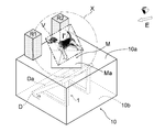
- FIG. 1 is a diagram for explaining the basic configuration of the exhibition apparatus according to the first embodiment of the present invention
- FIG. 2 is an external perspective view of the exhibition apparatus according to the first embodiment.
- a part of a casing such as a case and a housing and parts such as wiring and electrical components are omitted.
- the “image I” displayed on the display surface Da of the display D and the “spatial image I ′” that is a projection image thereof are exaggerated in thickness so that they are not actually (two-dimensional plane). I'm drawing.
- the display apparatus in this embodiment includes a panel-like micromirror array imaging optical element (hereinafter referred to as “micromirror array M” or simply “array M”) and a flat panel display such as an LCD ( Hereinafter, the display D) and the display mounting table 1 that supports the display D in an obliquely inclined manner below the array M (inside the case 10) are mainly configured.
- the display apparatus has a display surface with respect to one surface (lower surface Mb) of the array M by reflection of light by a number of micromirrors (corner reflectors: see FIGS. 11 and 12) provided in the micromirror array M.
- An image (image I) displayed on the display D arranged in a state where Da is inclined at a predetermined angle ⁇ is an aerial image I ′ rising obliquely in the space on the other surface (upper surface Ma) side of the array M. As shown in FIG.
- the exhibition apparatus has “exhibits for reinforcing the stereoscopic effect of the spatial image I ′” (front exhibits F1, F2) placed on the upper surface 10a of the case 10.
- Each of the front exhibits F1 and F2 has a distance (shortest distance) L from the center (point O: see FIG. 1) of the virtual display area V of the aerial image I ′ that is the diagonal length of the virtual display area V. It is arrange
- positioned in the position used as X or less (L ⁇ X). This is a feature of the display device of the present invention.
- the exhibit for reinforcing the three-dimensional effect of the aerial image I ′ covers the array M in a region other than the upper surface Ma of the array M so as not to disturb the image formation by the micromirror array M. It is placed so that there is no.
- a collection of points whose distance from the center (point O) of the virtual display area V (two-dimensional plane) is “diagonal length X of the virtual display area V” (in the figure, (Drawn with an alternate long and short dash line X) is a “sphere” centered on the point O.
- the display device of the first embodiment includes a plurality of the exhibits (F1, F2), and an upward inclination of the aerial image I ′.
- the front exhibits F1 and F2 are positioned in the left and right positions symmetrical with respect to the case horizontal center line of the virtual display area V.
- they are arranged in pairs at a position closer to the viewer than the aerial image I ′.
- the display device of the present embodiment and the video display method using the display device improve the stereoscopic effect and the realistic sensation of the aerial image I ′ as compared to the conventional display device (FIG. 18 and the like).
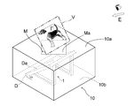
- FIG. 3 shows an example (second embodiment) in which the exhibits (middle exhibits C1, C2) for enhancing the three-dimensional effect are arranged on the left and right sides of the space image I ′ as viewed from the viewer (E).
- FIG. 4 shows an example (third embodiment) in which the exhibits (rear exhibits R1, R2) are arranged behind the aerial image I ′ when viewed from the viewer (E).
- the middle exhibits C1 and C2 are arranged in pairs at left and right positions that are symmetrical with respect to the center line of the virtual display region V in the left-right direction of the case. It is installed. Therefore, when the aerial image I ′ is displayed on the upper side of the case 10 (micromirror array M), the entity (exhibits C1, C2) is present in the vicinity of the aerial image I ′. Binocular parallax occurs between them, and the stereoscopic effect and presence of the spatial image I ′ are improved as compared with the conventional display device.
- each of the rear exhibits R1, R2 is in a left-right position that is symmetric with respect to the case horizontal direction center line of the virtual display region V and the space.
- a pair is disposed at a position on the back side away from the image I ′.
- the aerial image I ′ is displayed on the upper side of the case 10 (micromirror array M)
- binocular parallax occurs between the aerial image I ′ and the rear exhibits R1 and R2
- the rear exhibits R1 and R2 serve as the background of the aerial image I ′, and the stereoscopic effect and presence of the aerial image I ′ are further improved.
- FIGS. 5 and 6 show examples in which the front exhibits F1, F2, the middle exhibits C1, C2, and the rear exhibits R1, R2 are all arranged on the upper surface 10a of the case 10 (first). 4), each of the exhibits F1, F2, C1, C2, R1, and R2 has a distance L from the center (point O) of the virtual display area V of the aerial image I ′. It is arranged so as to surround this aerial image I ′ at a position where the diagonal length X of the display area V is equal to or smaller than (L ⁇ X).
- the conventional display can be achieved by displaying the projected spatial image I ′ in the circular space formed by these exhibits F1, F2, C1, C2, R1, and R2.
- the stereoscopic effect and the realistic sensation of the aerial image I ′ are improved.
- it is more sophisticated (complex) due to the distance (gap) between the exhibits F1, F2, C1, C2, R1, R2, and the shadows produced by these exhibits F1, F2, C1, C2, R1, R2. Binocular parallax can be generated.
- the display apparatus of the present embodiment and the video display method using the display apparatus further improve the stereoscopic effect and the realistic sensation of the aerial image I ′.
- the exhibits arranged on the upper surface of the casing (case 10) are cuboids (columnar) as models, but the exhibits used are resin, metal, ceramics 3D objects made of paper and paper that can be picked up by hand, such as general products (small items), character products such as mascots and figures, vehicles, buildings, animals and plants, models of celestial bodies, etc. be able to.
- the exhibit F3 arranged on the upper surface 10a of the case 10 has a beam-like member (F ′) or a space between the upper portions of the columnar front exhibits F1 and F2. It is formed by connecting with a bridge-like member or the like.
- the beam-like member F ′ corresponds to the aerial image I ′. It is arranged at a position where a part or a part of the array upper surface Ma is concealed. And from a gap (gate-like gap) formed between the beam-like member F ′ of the exhibit F3 and the upper surface 10a of the case 10, a part (front corner) of the micromirror array M is formed. It is visible from the viewer.
- the exhibit F4 arranged on the upper surface 10a of the case 10 is arranged between the upper parts of the columnar front and rear exhibits (two each).
- a beam-like member (F ′, C ′, C ′, R ′) connected to the frame is formed in a frame shape.
- the beam member F ′ on the front side is the aerial image I ′.
- it is arranged at a position to hide a part of the array upper surface Ma.
- a part (front corner) of the micromirror array M is formed from a gap (a gate-like gap) formed between the beam member F ′ on the front side of the exhibit F4 and the case upper surface 10a. It is visible from the viewer.
- a frame-like exhibit F5 similar to the exhibit F4 is arranged along the outer edge shape of the micromirror array M (upper surface Ma).
- beam-like members F ′, F ′, R ′, R ′
- the frame-like exhibition F5 is different from the exhibitions F3 and F4, and the beam-like members F ′, F ′, R ′, and R are viewed from the viewpoint E side (the right side in the figure) of the viewer. “Is placed at a position that does not obscure the aerial image I (does not obstruct projection).
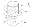
- the exhibit F6 arranged on the upper surface 10a of the case 10 is formed in a hollow cylindrical shape, and the exhibit F6 is a transparent or translucent resin. Etc. are used.
- the exhibit F6 can be seen through the peripheral surface (side surface) of the aerial image I '.
- the exhibit F6 is also a region other than the upper surface Ma of the micromirror array M, and at least a part of the center (point O) of the virtual display region V of the aerial image I ′. ) Is positioned and placed at a position where the diagonal length X of the virtual display region V is equal to or less than the diagonal length X (L ⁇ X).
- various lenses including a Fresnel lens and the like, and refractive imaging elements such as afocal optical micromirrors and corner reflectors can be used.
- a micromirror array M convex corner reflector array
- the micromirror array M is arranged so as to be substantially horizontal with respect to the viewer's viewpoint (sense) by an arbitrary fixing member or the like.
- the micromirror array (corner reflector array) M will be described in more detail. As shown in FIG. 11, the micromirror array M has a large number of minute convexes on the lower surface Mb side of the substrate (substrate) 11.
- the square columnar unit optical elements 12 (corner reflectors) are arranged in a diagonal grid pattern (FIG. 11 is a view of the array M viewed from below).
- Each of the square columnar unit optical elements 12 of the micromirror array M has a pair of (two) light reflecting surfaces (a first side surface 12a and a second side surface 12b on the side of the square column) that form a corner reflector.
- Each is formed in a rectangular shape having a “ratio of the vertical length (height h) in the substrate thickness direction to the horizontal width (width w) in the substrate surface direction” [aspect ratio (h / w)] of 1.5 or more. .
- each unit optical element 12 has a pair of light reflecting surfaces (a first side surface 12a and a second side surface 12b) constituting each corner 12c.
- the outer edge (outer side) is rotated by 45 ° with respect to the front of the viewer.
- the lower image I of the micromirror array M is projected to a plane-symmetric position (above the imaging optical element) with respect to the array M (element surface P) so that the aerial image I ′ is formed. It has become.
- the panel-shaped imaging optical element used in the display device of the present invention has a dicing process using a rotary blade on the surface of a flat transparent substrate.
- Two or one optical element (micromirror array M1, M2, M3, M4, see FIGS. 13 to 17) in which a plurality of linear grooves parallel to each other are formed at a predetermined interval may be used. .
- micromirror arrays M1, M2, M3, and M4 are superposed in a state where one of two optical elements (substrates) having a plurality of parallel grooves on the surface is rotated by 90 ° (FIGS. 13 and 14).
- FIG. 15 and FIG. 16 or a plurality of parallel grooves perpendicular to each other in plan view are formed on the front and back surfaces of one flat substrate (FIG. 17).
- Direction one parallel groove group and the other parallel groove group intersect each other at the crossing point (intersection of the lattice) perpendicular to each other in plan view.
- a corner reflector composed of the light-reflective vertical surface (wall surface) of the other parallel groove group.
- the light reflecting wall surface of the parallel groove group of the one substrate and the light reflecting wall surface of the parallel groove group of the other substrate, which constitute the corner reflector, are viewed three-dimensionally (three-dimensionally). In this case, there is a so-called “twist position” relationship. Further, since each of the parallel grooves and the light reflecting wall surface thereof are formed by dicing using a rotary blade, the aspect ratio [height (length in the substrate thickness direction) of the light reflecting surface in the corner reflector is used. ) / Width (width in the horizontal direction of the substrate)], for example, it is advantageous in that the optical performance of the optical element can be adjusted relatively easily.
- the micromirror array M1 shown in FIGS. 13 and 14 includes a transparent flat substrate 21 of each optical element (21, 21 ′) constituting the micromirror array M1, A plurality of linear grooves 21g or grooves 21'g parallel to each other are formed at predetermined intervals on the upper surfaces 21a, 21'a of 21 'by dicing using a rotary blade.
- the micromirror array M1 uses the two optical elements (substrates 21 and 21 ′) having the same shape to invert the upper one substrate 21 ′ as shown in FIG. ′ Is rotated by 90 ° (on the plane) with respect to the other substrate 21 on the lower side, the surface 21′a in which the groove 21′g is formed on the upper substrate 21 ′ is replaced with the lower substrate 21.
- This is configured as a set of arrays M1 (FIG. 13) in which the continuous directions of g are orthogonal to each other in plan view.
- the upper substrate 21 is arranged such that the continuous direction of the grooves 21g and the grooves 21′g provided on the substrates 21 and 21 ′ is orthogonal to each other in plan view. 'Is rotated with respect to the other substrate 21 on the lower side (90 ° on the horizontal plane), and the rear surface 21' of the upper substrate 21 'is formed on the surface 21a in which the groove 21g is formed in the lower substrate 21. b (no groove 21′g is formed) is brought into contact with each other, and the substrates 21 and 21 ′ are overlapped and fixed vertically to form a set of arrays M2.
- the micromirror array M3 shown in FIG. 16 uses the two optical elements (substrates 21 and 21 ′) having the same shape and manufacturing method as described above to invert one of the lower substrates 21 ′ and reverse this substrate.
- the back surface 21b of the upper substrate 21 and the back surface 21′b of the lower substrate 21 ′ are brought into contact with each other.
- 21 ′ are stacked and fixed one above the other to constitute a set of arrays M3 in which the continuous directions of the grooves 21g and the grooves 21′g provided on the substrates 21, 21 ′ are orthogonal to each other in plan view. Has been.
- the micromirror array M4 shown in FIG. 17 has linear grooves parallel to each other on the upper surface 31a and the lower back surface 31b of the transparent flat substrate 31 by dicing using a rotary blade.
- a plurality of grooves 31g and grooves 31g ' are formed at a predetermined interval.
- the grooves 31g on the front surface 31a side and the grooves 31g' on the back surface 31b side are perpendicular to each other in the direction of formation (continuous direction). It is formed to do.
- the planar two-dimensional image I (video etc.) displayed on the display D is the same as the exhibition apparatus using the micromirror array M.
- the exhibition apparatus has an advantage that the cost of the entire apparatus can be reduced because the micromirror array (M1, M2, M3, M4) to be used is inexpensive.
- the flat panel display (display D) for displaying the image I is in front of the viewer with respect to the lower surface Mb of the micromirror array M as shown in FIGS.
- the aerial image I ′ projected through the micromirror array M is directed toward the viewer, and is arranged so as to incline downward from the (front E side) toward the back side by a predetermined inclination angle ⁇ . It is like that.
- the display D used for displaying the image I a liquid crystal display panel (LCD) having a backlight, a plasma display panel, an organic EL display panel, and the like, “white” with no bias as much as possible over the entire visible light wavelength.
- a display panel that can reproduce “black” when not displayed with good contrast can be used.
- the display D may be a display unit such as a mobile phone or a portable information terminal.
- the size of the display surface Da is the size (planar shape) of the micromirror array M. The corresponding size can be used.
- the inclination angle ⁇ of the display D is set to 30 ° or more and less than 90 ° (30 ° ⁇ ⁇ ⁇ 90 °) in consideration of the posture, distance, etc. of the viewer who uses this display device.
- the box-shaped case 10 has been described as an example of the case that accommodates the display D.
- a case of another shape or an open case is used as the case used in the display device of the present invention. Any shape can be used as long as there is a space for placing an exhibit on the upper surface (top plate member) such as a shaped housing.
- the comparative example (display device) and example (exhibit device) used in the above verification are displayed on the display, the configuration and shape of the imaging optical element, the display, and the case other than the exhibits placed on the upper surface of the device. 10 subjects (monitors) who randomly extracted these devices from people who had never seen them, with the same conditions such as the image and surrounding environment. , Which display looks more three-dimensional?
- the configuration of the display device (display device) used for the evaluation is as follows. Comparative Example 1-Conventional display device shown in FIG. 18 (no exhibit) Example 1 Exhibition apparatus (exhibitions F1, F2) described in the first embodiment (FIG. 2) Example 2 Exhibition apparatus described in the fourth embodiment (FIG. 6) (exhibits F1, F2, C1, C2, R1, R2) Example 3 Exhibition apparatus (exhibit F5) described in the seventh embodiment (FIG. 9)
- the result of sensory evaluation is -About 10 people who answered that the apparatus of Example 1 feels a three-dimensional effect of the aerial image more than the apparatus of Comparative Example 1-About the apparatus of Example 2, compared to the apparatus of Comparative Example 1, the space 10 people / 10 people who answered that they feel more three-dimensionality of the image 10 people / 10 people who answered that the device of Example 3 feels more three-dimensionality of the aerial image than the device of Comparative Example 1
- the display apparatus of the present invention and the video display method using the display apparatus are suitable for projecting a related video around a three-dimensional object, such as a diorama, a plastic model, a solid model, a garage kit, a paper model, etc. Or, it is suitable for display / display of minicars, food toys, figures and the like. In addition to commercial use using characters, product models, etc., it can also be used in academic and educational fields, such as visualization of the structure of chemical substances that are difficult to express with a three-dimensional model alone.
Landscapes
- Physics & Mathematics (AREA)
- General Physics & Mathematics (AREA)
- Optics & Photonics (AREA)
- Business, Economics & Management (AREA)
- Accounting & Taxation (AREA)
- Marketing (AREA)
- Engineering & Computer Science (AREA)
- Theoretical Computer Science (AREA)
- Optical Elements Other Than Lenses (AREA)
- Devices For Indicating Variable Information By Combining Individual Elements (AREA)
Abstract
Description
L≦X ・・・(1)
〔式(1)において、Lは、仮想表示領域の中心と展示物の間の距離。Xは、仮想表示領域の対角長さもしくは仮想表示領域の最大径のうちの長い方の値。〕
L≦X ・・・(1)
〔式(1)において、Lは、仮想表示領域の中心と展示物の間の距離。Xは、仮想表示領域の対角長さもしくは仮想表示領域の最大径のうちの長い方の値。〕
L≦X ・・・(1)
〔上記式(1)において、Lは、仮想表示領域の中心と展示物の間の距離。Xは、仮想表示領域の対角長さもしくは仮想表示領域の最大径のうちの長い方の値。〕
L≦X ・・・(1)
〔上記式(1)において、Lは、仮想表示領域の中心と展示物の間の距離。Xは、仮想表示領域の対角長さもしくは仮想表示領域の最大径のうちの長い方の値。〕
つぎに、前記各実施形態の構成の展示装置のうちのいくつかを選んで、装置上面に配置される展示物による「空間像の立体感の向上効果」を、従来の構成の表示装置(展示物の無い、図18の構成)との比較により検証した例について、説明する。
・比較例1-図18に記載の従来の表示装置(展示物なし)
・実施例1-第1実施形態(図2)に記載の展示装置(展示物F1,F2)
・実施例2-第4実施形態(図6)に記載の展示装置(展示物F1,F2,C1,C2,R1,R2)
・実施例3-第7実施形態(図9)に記載の展示装置(展示物F5)
・実施例1の装置について、比較例1の装置に比べ、空間像の立体感をより感じると答えた人 10名/10人
・実施例2の装置について、比較例1の装置に比べ、空間像の立体感をより感じると答えた人 10名/10人
・実施例3の装置について、比較例1の装置に比べ、空間像の立体感をより感じると答えた人 10名/10人
10 ケース
10a 上面
10b 底部
11 基板
12 単位光学素子
12a,12b 側面
12c コーナー
21,21’ 基板
21a,21’a 表面
21b,21’b 裏面
21g,21’g 溝
31 基板
31a 表面
31b 裏面
31g,31g’ 溝
D ディスプレイ
Da 表示面
F,C,R 展示物
M マイクロミラーアレイ
Ma 上面
Mb 下面
I 画像
I’ 空間像
V 空間像の仮想表示領域
X 仮想表示領域の対角長さ
L 展示物と仮想表示領域の中心との距離
Claims (10)
- ディスプレイを収容する筐体の上面に光透過状に配設された結像光学素子と、この結像光学素子の下側に、結像光学素子の下面に対してその表示面が所定角度傾斜した状態で配置されたディスプレイと、上記筐体の上面に配置された展示物とを備え、上記ディスプレイの表示面に表示された映像を、上記結像光学素子を介して、結像光学素子の素子面に対して上記表示面と面対称となる空間位置に形成される仮想表示領域内に、斜め状に立ち上がる空間像として結像させ、この空間像を上記展示物と関連させて表示する展示装置であって、筐体の上面における上記展示物が、上記結像光学素子の上面以外の領域で、かつ、下記式(1)を満たす位置に配置されていることを特徴とする展示装置。
L≦X ・・・(1)
〔式(1)において、Lは、仮想表示領域の中心と展示物の間の距離。Xは、仮想表示領域の対角長さもしくは仮想表示領域の最大径のうちの長い方の値。〕 - 上記展示物を複数個備え、これら複数個の展示物のうちの少なくとも1組が、上記仮想表示領域の左右方向中心線に対して対称となる左右位置に、対となって配設されている請求項1記載の展示装置。
- 上記結像光学素子が、コーナーリフレクタ型の単位光学素子からなるマイクロミラーアレイである請求項1または2記載の展示装置。
- 上記結像光学素子の下面に対する上記ディスプレイの表示面の傾斜角が、30°以上90°未満に設定されている請求項1~3のいずれか一項に記載の展示装置。
- 筐体の上面に光透過状に配設された結像光学素子を介して、この結像光学素子の下側に下り傾斜状に配設されたディスプレイの表示面に表示された映像を、上記表示面に対応して上記筐体の上方の空間に形成される仮想表示領域内に、斜め状に立ち上がる空間像として結像させ、この空間像を、上記筐体の上面に配置された展示物と合わせて展示する映像展示方法であって、
上記筐体の上面における上記結像光学素子の上面以外の領域に、上記空間像の立体感を補強するための展示物を、下記式(1)を満たすように配置して、展示を行うことを特徴とする映像展示方法。
L≦X ・・・(1)
〔式(1)において、Lは、仮想表示領域の中心と展示物の間の距離。Xは、仮想表示領域の対角長さもしくは仮想表示領域の最大径のうちの長い方の値。〕 - 上記立体感を補強するための展示物を複数個備え、上記空間像の上り傾斜に正対する筐体前側から見た場合、上記複数個の展示物のうちの少なくとも1組が、上記仮想表示領域の左右方向中心線に対して対称となる左右位置に、対となって配設されている請求項5記載の映像展示方法。
- 上記左右対称に配置された展示物の組のうちの少なくとも1組を、上記筐体の上方に結像する空間像より前側で、かつ、上記結像光学素子の縁部に隣接する位置に載置して展示を行う請求項6記載の映像展示方法。
- 上記空間像より前側の位置に配置された左右の展示物が、空間像の上り傾斜に正対する筐体前側から見た場合、この空間像の一部を隠蔽する位置に載置されているか、もしくは、これら展示物の間が、上記空間像の一部を隠蔽する梁状部材または橋状部材で連結されている請求項7記載の映像展示方法。
- 上記左右対称に配置された展示物の組のうちの少なくとも1組を、上記筐体の上方に結像する空間像より後側で、かつ、上記結像光学素子の縁部に隣接する位置に載置して展示を行う請求項6記載の映像展示方法。
- 上記左右対称に配置された展示物の組のうちの少なくとも1組を、上記筐体の上方に結像する空間像より左右側で、かつ、上記結像光学素子の縁部に隣接する位置に載置して展示を行う請求項6記載の映像展示方法。
Priority Applications (2)
| Application Number | Priority Date | Filing Date | Title |
|---|---|---|---|
| CN201480029498.2A CN105229515A (zh) | 2013-06-07 | 2014-05-21 | 展示装置以及影像展示方法 |
| US14/894,872 US9910409B2 (en) | 2013-06-07 | 2014-05-21 | Exhibition device and video picture exhibition method |
Applications Claiming Priority (2)
| Application Number | Priority Date | Filing Date | Title |
|---|---|---|---|
| JP2013120847A JP2014238492A (ja) | 2013-06-07 | 2013-06-07 | 展示装置および映像展示方法 |
| JP2013-120847 | 2013-06-07 |
Publications (1)
| Publication Number | Publication Date |
|---|---|
| WO2014196356A1 true WO2014196356A1 (ja) | 2014-12-11 |
Family
ID=52008008
Family Applications (1)
| Application Number | Title | Priority Date | Filing Date |
|---|---|---|---|
| PCT/JP2014/063426 Ceased WO2014196356A1 (ja) | 2013-06-07 | 2014-05-21 | 展示装置および映像展示方法 |
Country Status (4)
| Country | Link |
|---|---|
| US (1) | US9910409B2 (ja) |
| JP (1) | JP2014238492A (ja) |
| CN (1) | CN105229515A (ja) |
| WO (1) | WO2014196356A1 (ja) |
Cited By (2)
| Publication number | Priority date | Publication date | Assignee | Title |
|---|---|---|---|---|
| US20180003997A1 (en) * | 2015-01-08 | 2018-01-04 | Nitto Denko Corporation | Exhibition device and video picture exhibition method |
| CN113612983A (zh) * | 2021-08-11 | 2021-11-05 | 张云峰 | 一种基于vr技术的可视化展示展览系统及其使用方法 |
Families Citing this family (4)
| Publication number | Priority date | Publication date | Assignee | Title |
|---|---|---|---|---|
| CN109979252A (zh) * | 2019-03-15 | 2019-07-05 | 黄河水利职业技术学院 | 可以充分优化教师讲课内容的高效教学系统 |
| KR102231649B1 (ko) * | 2019-10-21 | 2021-03-24 | 김동욱 | 3d데이터를 이용하여 쌍방향 인터랙션이 가능한 홀로그램 생성 장치 및 방법 |
| JP7251828B2 (ja) * | 2020-09-17 | 2023-04-04 | 神田工業株式会社 | 展示装置及び展示方法 |
| CN118466046A (zh) * | 2023-02-08 | 2024-08-09 | 群创光电股份有限公司 | 图像显示装置 |
Citations (3)
| Publication number | Priority date | Publication date | Assignee | Title |
|---|---|---|---|---|
| JP2001330916A (ja) * | 2000-05-23 | 2001-11-30 | Photo Craft Sha:Kk | 視覚表示方法および装置 |
| JP2011081296A (ja) * | 2009-10-09 | 2011-04-21 | Pioneer Electronic Corp | 表示装置 |
| WO2011052588A1 (ja) * | 2009-10-28 | 2011-05-05 | シャープ株式会社 | 光学システム |
Family Cites Families (9)
| Publication number | Priority date | Publication date | Assignee | Title |
|---|---|---|---|---|
| JP3983953B2 (ja) | 2000-03-10 | 2007-09-26 | パイオニア株式会社 | 立体的2次元画像表示装置及び画像表示方法 |
| JP3980242B2 (ja) | 2000-03-10 | 2007-09-26 | パイオニア株式会社 | 立体的2次元画像表示装置及び画像表示方法 |
| KR101018523B1 (ko) | 2006-03-23 | 2011-03-03 | 도쿠리츠 교세이 호진 죠호 츠신 켄큐 키코 | 결상 소자, 디스플레이 장치 |
| CN101641630B (zh) * | 2007-03-05 | 2011-11-23 | 独立行政法人情报通信研究机构 | 多视点空中映像显示元件 |
| JP4267668B2 (ja) * | 2007-03-08 | 2009-05-27 | 株式会社日立製作所 | 立体像表示装置 |
| JP5392613B2 (ja) * | 2009-09-28 | 2014-01-22 | スタンレー電気株式会社 | ヘッドアップディスプレイ |
| JP5614745B2 (ja) * | 2010-12-03 | 2014-10-29 | スタンレー電気株式会社 | 2面コーナーリフレクタアレイ光学素子を用いた表示装置 |
| US8692738B2 (en) * | 2011-06-10 | 2014-04-08 | Disney Enterprises, Inc. | Advanced Pepper's ghost projection system with a multiview and multiplanar display |
| EP3118664B1 (en) * | 2015-07-17 | 2019-06-19 | Lg Electronics Inc. | Micro mirror array, manufacturing method of the micro mirror array, and floating display device including the micro mirror array |
-
2013
- 2013-06-07 JP JP2013120847A patent/JP2014238492A/ja active Pending
-
2014
- 2014-05-21 CN CN201480029498.2A patent/CN105229515A/zh active Pending
- 2014-05-21 WO PCT/JP2014/063426 patent/WO2014196356A1/ja not_active Ceased
- 2014-05-21 US US14/894,872 patent/US9910409B2/en not_active Expired - Fee Related
Patent Citations (3)
| Publication number | Priority date | Publication date | Assignee | Title |
|---|---|---|---|---|
| JP2001330916A (ja) * | 2000-05-23 | 2001-11-30 | Photo Craft Sha:Kk | 視覚表示方法および装置 |
| JP2011081296A (ja) * | 2009-10-09 | 2011-04-21 | Pioneer Electronic Corp | 表示装置 |
| WO2011052588A1 (ja) * | 2009-10-28 | 2011-05-05 | シャープ株式会社 | 光学システム |
Cited By (3)
| Publication number | Priority date | Publication date | Assignee | Title |
|---|---|---|---|---|
| US20180003997A1 (en) * | 2015-01-08 | 2018-01-04 | Nitto Denko Corporation | Exhibition device and video picture exhibition method |
| CN113612983A (zh) * | 2021-08-11 | 2021-11-05 | 张云峰 | 一种基于vr技术的可视化展示展览系统及其使用方法 |
| CN113612983B (zh) * | 2021-08-11 | 2024-01-19 | 张云峰 | 一种基于vr技术的可视化展示展览系统及其使用方法 |
Also Published As
| Publication number | Publication date |
|---|---|
| CN105229515A (zh) | 2016-01-06 |
| US9910409B2 (en) | 2018-03-06 |
| JP2014238492A (ja) | 2014-12-18 |
| US20160116886A1 (en) | 2016-04-28 |
Similar Documents
| Publication | Publication Date | Title |
|---|---|---|
| KR101365218B1 (ko) | 3차원 영상표시장치 및 이를 이용한 영상표시방법 | |
| US20180284470A1 (en) | Display device, and display method for aerial image | |
| JP5992302B2 (ja) | 表示装置 | |
| WO2014196356A1 (ja) | 展示装置および映像展示方法 | |
| JP6143161B2 (ja) | 表示装置 | |
| US20120200916A1 (en) | Multi-Stereoscopic Viewing Apparatus | |
| US11592686B2 (en) | Touchable and 360-degree playable holographic display | |
| JPWO2006061959A1 (ja) | 立体的二次元画像表示装置及び立体的二次元画像表示方法 | |
| JP6115998B2 (ja) | 展示装置 | |
| JP2013228671A (ja) | 表示装置 | |
| WO2012142803A1 (zh) | 一种用于广告展示的三维立体成像设备和方法 | |
| KR101848353B1 (ko) | 홀로그램 영상 구현을 위한 스마트폰용 홀로그램 투사장치 | |
| JP6583954B2 (ja) | 展示装置および映像展示方法 | |
| Miyazaki et al. | Floating three-dimensional image display using micro-mirror array imaging element | |
| WO2010095486A1 (ja) | 立体表示装置 | |
| US11226493B2 (en) | Display system for producing daylight-visible holographic or floating 3D imagery | |
| CN201122207Y (zh) | 幻影成像装置 | |
| CN101206306A (zh) | 幻影成像装置 | |
| JP5045917B2 (ja) | 立体ディスプレイ | |
| JP2021103269A (ja) | 画像表示装置 | |
| JP6465378B2 (ja) | 情報表示装置 | |
| WO2006035817A1 (ja) | 立体的二次元画像表示装置及び立体的二次元画像表示方法 | |
| US20260099059A1 (en) | Double-sided, multiplane, backward refraction imaging device for use in optics related stem education | |
| JP2009205058A (ja) | 立体視表示装置 | |
| WO2007052261A2 (en) | A screen projection system |
Legal Events
| Date | Code | Title | Description |
|---|---|---|---|
| WWE | Wipo information: entry into national phase |
Ref document number: 201480029498.2 Country of ref document: CN |
|
| 121 | Ep: the epo has been informed by wipo that ep was designated in this application |
Ref document number: 14807544 Country of ref document: EP Kind code of ref document: A1 |
|
| WWE | Wipo information: entry into national phase |
Ref document number: 14894872 Country of ref document: US |
|
| NENP | Non-entry into the national phase |
Ref country code: DE |
|
| 122 | Ep: pct application non-entry in european phase |
Ref document number: 14807544 Country of ref document: EP Kind code of ref document: A1 |