WO2014196065A1 - 過電圧保護装置及び過電圧保護システム - Google Patents
過電圧保護装置及び過電圧保護システム Download PDFInfo
- Publication number
- WO2014196065A1 WO2014196065A1 PCT/JP2013/065724 JP2013065724W WO2014196065A1 WO 2014196065 A1 WO2014196065 A1 WO 2014196065A1 JP 2013065724 W JP2013065724 W JP 2013065724W WO 2014196065 A1 WO2014196065 A1 WO 2014196065A1
- Authority
- WO
- WIPO (PCT)
- Prior art keywords
- bus
- overvoltage protection
- abnormality detection
- detection signal
- positive
- Prior art date
- Legal status (The legal status is an assumption and is not a legal conclusion. Google has not performed a legal analysis and makes no representation as to the accuracy of the status listed.)
- Ceased
Links
Images

Classifications
-
- H—ELECTRICITY
- H02—GENERATION; CONVERSION OR DISTRIBUTION OF ELECTRIC POWER
- H02H—EMERGENCY PROTECTIVE CIRCUIT ARRANGEMENTS
- H02H7/00—Emergency protective circuit arrangements specially adapted for specific types of electric machines or apparatus or for sectionalised protection of cable or line systems, and effecting automatic switching in the event of an undesired change from normal working conditions
- H02H7/08—Emergency protective circuit arrangements specially adapted for specific types of electric machines or apparatus or for sectionalised protection of cable or line systems, and effecting automatic switching in the event of an undesired change from normal working conditions for dynamo-electric motors
- H02H7/085—Emergency protective circuit arrangements specially adapted for specific types of electric machines or apparatus or for sectionalised protection of cable or line systems, and effecting automatic switching in the event of an undesired change from normal working conditions for dynamo-electric motors against excessive load
- H02H7/0854—Emergency protective circuit arrangements specially adapted for specific types of electric machines or apparatus or for sectionalised protection of cable or line systems, and effecting automatic switching in the event of an undesired change from normal working conditions for dynamo-electric motors against excessive load responsive to rate of change of current, couple or speed, e.g. anti-kickback protection
-
- H—ELECTRICITY
- H02—GENERATION; CONVERSION OR DISTRIBUTION OF ELECTRIC POWER
- H02H—EMERGENCY PROTECTIVE CIRCUIT ARRANGEMENTS
- H02H7/00—Emergency protective circuit arrangements specially adapted for specific types of electric machines or apparatus or for sectionalised protection of cable or line systems, and effecting automatic switching in the event of an undesired change from normal working conditions
- H02H7/08—Emergency protective circuit arrangements specially adapted for specific types of electric machines or apparatus or for sectionalised protection of cable or line systems, and effecting automatic switching in the event of an undesired change from normal working conditions for dynamo-electric motors
- H02H7/093—Emergency protective circuit arrangements specially adapted for specific types of electric machines or apparatus or for sectionalised protection of cable or line systems, and effecting automatic switching in the event of an undesired change from normal working conditions for dynamo-electric motors against increase beyond, or decrease below, a predetermined level of rotational speed
-
- H—ELECTRICITY
- H02—GENERATION; CONVERSION OR DISTRIBUTION OF ELECTRIC POWER
- H02H—EMERGENCY PROTECTIVE CIRCUIT ARRANGEMENTS
- H02H7/00—Emergency protective circuit arrangements specially adapted for specific types of electric machines or apparatus or for sectionalised protection of cable or line systems, and effecting automatic switching in the event of an undesired change from normal working conditions
- H02H7/10—Emergency protective circuit arrangements specially adapted for specific types of electric machines or apparatus or for sectionalised protection of cable or line systems, and effecting automatic switching in the event of an undesired change from normal working conditions for converters; for rectifiers
- H02H7/12—Emergency protective circuit arrangements specially adapted for specific types of electric machines or apparatus or for sectionalised protection of cable or line systems, and effecting automatic switching in the event of an undesired change from normal working conditions for converters; for rectifiers for static converters or rectifiers
- H02H7/1216—Emergency protective circuit arrangements specially adapted for specific types of electric machines or apparatus or for sectionalised protection of cable or line systems, and effecting automatic switching in the event of an undesired change from normal working conditions for converters; for rectifiers for static converters or rectifiers for AC-AC converters
-
- H—ELECTRICITY
- H02—GENERATION; CONVERSION OR DISTRIBUTION OF ELECTRIC POWER
- H02H—EMERGENCY PROTECTIVE CIRCUIT ARRANGEMENTS
- H02H7/00—Emergency protective circuit arrangements specially adapted for specific types of electric machines or apparatus or for sectionalised protection of cable or line systems, and effecting automatic switching in the event of an undesired change from normal working conditions
- H02H7/10—Emergency protective circuit arrangements specially adapted for specific types of electric machines or apparatus or for sectionalised protection of cable or line systems, and effecting automatic switching in the event of an undesired change from normal working conditions for converters; for rectifiers
- H02H7/12—Emergency protective circuit arrangements specially adapted for specific types of electric machines or apparatus or for sectionalised protection of cable or line systems, and effecting automatic switching in the event of an undesired change from normal working conditions for converters; for rectifiers for static converters or rectifiers
- H02H7/122—Emergency protective circuit arrangements specially adapted for specific types of electric machines or apparatus or for sectionalised protection of cable or line systems, and effecting automatic switching in the event of an undesired change from normal working conditions for converters; for rectifiers for static converters or rectifiers for inverters, i.e. DC/AC converters
- H02H7/1227—Emergency protective circuit arrangements specially adapted for specific types of electric machines or apparatus or for sectionalised protection of cable or line systems, and effecting automatic switching in the event of an undesired change from normal working conditions for converters; for rectifiers for static converters or rectifiers for inverters, i.e. DC/AC converters responsive to abnormalities in the output circuit, e.g. short circuit
-
- H—ELECTRICITY
- H02—GENERATION; CONVERSION OR DISTRIBUTION OF ELECTRIC POWER
- H02P—CONTROL OR REGULATION OF ELECTRIC MOTORS, ELECTRIC GENERATORS OR DYNAMO-ELECTRIC CONVERTERS; CONTROLLING TRANSFORMERS, REACTORS OR CHOKE COILS
- H02P29/00—Arrangements for regulating or controlling electric motors, appropriate for both AC and DC motors
- H02P29/02—Providing protection against overload without automatic interruption of supply
- H02P29/024—Detecting a fault condition, e.g. short circuit, locked rotor, open circuit or loss of load
- H02P29/0241—Detecting a fault condition, e.g. short circuit, locked rotor, open circuit or loss of load the fault being an overvoltage
Definitions
- the disclosed embodiment relates to an overvoltage protection device and an overvoltage protection system.
- Patent Document 1 a circuit breaker is disposed between the inverter and the permanent magnet AC motor, and the circuit breaker interrupts the electrical connection between the inverter and the permanent magnet AC motor based on the control of the motor ECU.
- An overvoltage protection device is described.
- the present invention has been made in view of such problems, and an object of the present invention is to provide an overvoltage protection device and an overvoltage protection system that can prevent adverse effects due to overvoltage from a rotating electrical machine to a power converter. .
- an overvoltage protection device connected to a rotating electrical machine, wherein a DC current input unit, a positive DC bus connected to the input unit, and a negative DC bus are connected to the input unit.
- Power converter comprising: a side DC bus; an AC converter connected to the positive DC bus and the negative DC bus; a first capacitor connected between the positive DC bus and the negative DC bus And a switch provided in a connection path between the AC converter of the power converter and the rotating electrical machine, and an abnormality detection that outputs an abnormality detection signal of at least one of the power converter and the rotating electrical machine
- the overvoltage protection device having a portion is applied.
- an overvoltage protection device connected to a rotating electrical machine, wherein a DC current input unit and a positive DC bus connected to the input unit, respectively. And a negative DC bus, an AC converter connected to the positive DC bus and the negative DC bus, a first capacitor connected between the positive DC bus and the negative DC bus, and the positive side At least one of a second capacitor and a resistor, the at least one of the second capacitor and the resistor, and the positive DC bus connected to the first capacitor between the DC bus and the negative DC bus
- a power converter having an open / close switch provided between the negative DC bus, an abnormality detection unit that outputs an abnormality detection signal of at least one of the power converter and the rotating electrical machine, A switch that is provided in a connection path between the AC converter of the power converter and the rotating electrical machine and that opens in response to the abnormality detection signal from the abnormality detector; the positive DC bus; and
- An overvoltage protection device having a switch control unit that closes and opens the
- the overvoltage protection device and the overvoltage protection system of the present invention it is possible to prevent adverse effects due to overvoltage from the rotating electrical machine to the power converter.
- the overvoltage protection system 1 of the present embodiment includes a rotary motor 2 (rotary electric machine) and an overvoltage protection device 3 connected to the motor 2.
- the motor 2 is configured as a so-called three-phase AC motor driven by three-phase (for example, U, V, W phase) AC power.
- the motor 2 is not limited to being configured as a three-phase AC motor driven by three-phase AC power, but is configured as a so-called single-phase AC motor driven by single-phase AC power. Also good.
- the motor 2 includes a stator and a rotor (none of which is shown) that is rotatably supported by the stator, and is coupled to the rotor by rotating the rotor with respect to the stator.
- the shaft (not shown) is rotated to output the rotational force.
- stator is configured as an armature having a winding (not shown), and the rotor is configured as a field having a magnet (not shown) that generates a magnetic field.
- the stator may be configured as a field having a magnet, and the rotor may be configured as an armature having a winding.
- the overvoltage protection device 3 cuts off the connection between the inverter device 10 (power conversion device) that converts DC power into AC power and the electromagnetic switch 20 (switch, the AC conversion unit of the power conversion device, and the rotating electrical machine. Means).
- the inverter device 10 includes a converter unit 11 (DC current input unit), a capacitor 12 (first capacitor, means for suppressing rise of voltage between the positive DC bus and the negative DC bus), and an inverter unit 13. (AC converter) and an abnormality detector 14 (means for detecting at least one abnormality of the power converter and the rotating electrical machine).
- a converter unit 11 DC current input unit
- a capacitor 12 first capacitor, means for suppressing rise of voltage between the positive DC bus and the negative DC bus
- an inverter unit 13 AC converter
- an abnormality detector 14 means for detecting at least one abnormality of the power converter and the rotating electrical machine.
- the converter unit 11 includes six diodes, rectifies three-phase (for example, R, S, and T-phase) AC power supplied from the three-phase AC power supply 4, and a DC bus P that is a positive DC bus, and DC power is supplied to a DC bus N which is a negative DC bus.
- the converter unit 11 is not limited to the case where it is configured by six diodes, and may have other configurations.
- the AC power supply for supplying AC power to the converter unit 11 is not limited to the three-phase AC power supply 4 for supplying three-phase AC power, and may be a single-phase AC power supply for supplying single-phase AC power or the like. .
- the power source for supplying power to the inverter device 10 is not limited to the AC power source for supplying AC power, but may be a DC power source for supplying DC power.
- the power source that supplies power to the inverter device 10 is a DC power source, the converter unit 11 is not necessarily required.
- the capacitor 12 is connected between the DC buses P and N, and absorbs or discharges the electric charge between the DC buses P and N due to capacitance.
- the inverter unit 13 is connected to the DC buses P and N, and includes six switching elements and six free-wheeling diodes connected in reverse parallel to the six switching elements.
- the inverter part 13 is not limited to when comprised with six switching elements and six free-wheeling diodes, Other structures may be sufficient.
- the inverter unit 13 converts DC power into three-phase (for example, U, V, W phase) AC power and supplies it to the motor 2.
- the abnormality detection unit 14 detects an abnormality in at least one of the inverter device 10 and the motor 2 that is driving the inverter device 10 and outputs a corresponding abnormality detection signal to an open / close switch 25 (described later) of the electromagnetic switch 20.
- the induced voltage (back electromotive voltage) applied from the motor 2 between the DC buses P and N exceeds the withstand voltage of the inverter device 10, thereby causing the inverter device 10 to There is a risk of adverse effects.
- the abnormality of at least one of the inverter device 10 and the motor 2 is variously exemplified and is not particularly limited.
- an abnormality in at least one of the inverter device 10 and the motor 2 is a torque abnormality (overtorque) that deviates from a presumed torque range, and deviates from a presumed speed range.
- a torque abnormality overtorque
- the abnormality detection unit 14 detects an overtorque detection signal that is a corresponding abnormality detection signal.
- the abnormality detection unit 14 detects an overspeed detection signal that is a corresponding abnormality detection signal.
- a speed deviation abnormality detection signal which is a corresponding abnormality detection signal, is output to the open / close switch 25 (described later) of the electromagnetic switch 20.
- the abnormality of at least one of the inverter device 10 and the motor 2 is at least one of overtorque, overspeed, and speed deviation abnormality.
- the case where the detection unit 14 outputs any one of an overtorque detection signal, an overspeed detection signal, and a speed deviation abnormality detection signal will be described.
- the type of abnormality detection signal output by the abnormality detection unit 14 is the above signal. It is not limited to.
- the electromagnetic switch 20 includes three contacts 21 to 23, an electromagnetic coil 24 to which single-phase AC power is supplied from the single-phase AC power supply 5, and an open / close switch 25.
- the power source that supplies power to the electromagnetic coil 24 is not limited to the single-phase AC power source 5 that supplies single-phase AC power, and may be a DC power source that supplies DC power.
- the contacts 21 to 23 are provided in connection paths w1 to w3 between the inverter unit 13 of the inverter device 10 and the motor 2, respectively. These contacts 21 to 23 are closed when the inverter device 10 is normally driven, that is, when none of the over-torque detection signal, over-speed detection signal, and speed deviation abnormality detection signal is input to the open / close switch 25. Thus, the inverter device 10 and the motor 2 are connected so that three-phase AC power is supplied to the motor 2.
- the open / close switch 25 is provided on the bus b1 (or the bus b2) among the buses b1 and b2 connected to the electromagnetic coil 24 and the single-phase AC power source 5.
- the open / close switch 25 is simply opened when the inverter device 10 is normally driven, that is, when none of the over-torque detection signal, over-speed detection signal, and speed deviation abnormality detection signal is input.
- the current from the phase AC power supply 5 is prevented from flowing into the electromagnetic coil 24 (the electromagnetic coil 24 is not conducted).
- an electromagnetic switch 20 at least one of overtorque, overspeed, and speed deviation abnormality occurs during driving of the inverter device 10, and an overtorque detection signal, an overspeed detection signal, and a speed deviation abnormality detection signal are detected.
- the open / close switch 25 When at least one of them is input to the open / close switch 25, the open / close switch 25 is closed to enter a closed state, so that a current from the single-phase AC power supply 5 flows to the electromagnetic coil 24.
- the contacts 21 to 23 are opened to enter an open state, thereby disconnecting (disconnecting) the connection between the inverter device 10 and the motor 2.
- the connection between the inverter device 10 and the motor 2 is cut off by the electromagnetic switch 20 will be described.
- connection between the inverter device 10 and the motor 2 is cut off by a switch other than the electromagnetic switch 20. May be. By the way, a predetermined time is required until the electromagnetic switch 20 completes the disconnection of the connection between the inverter device 10 and the motor 2.
- the electromagnetic switch 20 when at least one of the overtorque detection signal, the overspeed detection signal, and the speed deviation abnormality detection signal is input to the open / close switch 25 of the electromagnetic switch 20, the electromagnetic switch 20 is connected to the inverter device 10 and the motor.
- the connection with 2 is started.
- the capacitor 12 absorbs the electric charge between the DC buses P and N until a predetermined time elapses until the electromagnetic switch 20 completes the disconnection of the connection between the inverter device 10 and the motor 2. Thereby, the capacitor 12 suppresses the rise of the voltage between the DC buses P and N due to the induced voltage from the motor 2.
- FIG. 2 shows a graph in which the horizontal axis represents time t and the vertical axis represents the voltage V applied between the DC buses P and N.
- the voltage V between the DC buses P and N rises with time t.
- the capacitor 12 absorbs the electric charge between the DC buses P and N
- the increase in the voltage V between the DC buses P and N is slower (slower) than in the comparative example.
- the DC bus P, before the voltage V between the N is an overvoltage exceeding the breakdown voltage V max of the inverter 10, that blocking the connection between the inverter device 10 and the motor 2 by the electromagnetic switch 20 is completed, Eventually, the voltage V between the DC buses P and N becomes constant.
- the overvoltage protection device 3 of the present embodiment includes the abnormality detection unit 14 and the electromagnetic switch 20.
- the contacts 21 to 23 of the electromagnetic switch 20 are opened according to an abnormality detection signal from the abnormality detection unit 14, thereby connecting the inverter device 10 and the motor 2. Can be separated.
- a predetermined time is required until the electromagnetic switch 20 completes the disconnection of the connection between the inverter device 10 and the motor 2.
- the capacitor 12 is connected between the DC buses P and N.
- the capacitor 12 absorbs the electric charge between the DC buses P and N, so that the voltage between the DC buses P and N due to the induced voltage from the motor 2 is increased. Can be suppressed.
- the contacts 21 to 23 of the electromagnetic switch 20 open in response to an abnormality detection signal from the abnormality detection unit 14.
- the contacts 21 to 23 of the electromagnetic switch 20 By opening the contacts 21 to 23 of the electromagnetic switch 20 according to the abnormality detection signal from the abnormality detection unit 14, the connection between the inverter device 10 and the motor 2 can be reliably disconnected.
- the abnormality detection unit 14 outputs at least one of an overtorque detection signal, an overspeed detection signal, and a speed deviation abnormality detection signal.
- the overvoltage protection system 1 of this embodiment includes a motor 2 and an overvoltage protection device 3.
- the motor 2 is the same as that in the first embodiment.
- the overvoltage protection device 3 includes an inverter device 10, an electromagnetic switch 20, and a voltage detector 30 provided outside the inverter device 10.
- the voltage detector 30 may be provided inside the inverter device 10.
- the inverter device 10 includes a converter unit 11, a capacitor 12, an inverter unit 13, an abnormality detection unit 14, a capacitor 15 (second capacitor), a resistor 16, and an open / close switch 17.
- the converter unit 11, the capacitor 12, the inverter unit 13, and the abnormality detection unit 14 are the same as those in the first embodiment.
- the capacitor 15 and the resistor 16 are connected in parallel with the capacitor 12 between the DC buses P and N.
- the capacitor 15 absorbs or discharges the electric charge between the DC buses P and N due to the capacitance.
- the resistor 16 consumes power.
- the open / close switch 17 is provided between the capacitor 15 and the resistor 16 and the DC bus P (or DC bus N).
- the open / close switch 17 is opened when the inverter device 10 is normally driven, specifically when a switch control signal to be described later is not input, so that the capacitor 15 and the resistor are connected between the DC buses P and N. 16 is not connected (the capacitor 15 and the resistor 16 are not conducted).
- the electromagnetic switch 20 is the same as that in the first embodiment.
- the voltage detector 30 includes a voltage detection unit 31 and a switch control unit 32.
- the voltage detector 31 detects the voltage between the DC buses P and N.
- the switch control unit 32 outputs a control signal (hereinafter referred to as “switch control signal” as appropriate) to the open / close switch 17 of the inverter device 10 in accordance with the voltage value between the DC buses P and N detected by the voltage detection unit 31. . Specifically, the switch control unit 32 outputs a switch control signal to the open / close switch 17 when the voltage value between the DC buses P and N detected by the voltage detection unit 31 exceeds a predetermined voltage threshold value. To do.
- the electromagnetic switch 20 when at least one of the overtorque detection signal, the overspeed detection signal, and the speed deviation abnormality detection signal is input to the open / close switch 25 of the electromagnetic switch 20, the electromagnetic switch 20 is connected to the inverter device 10 and the motor.
- the connection with 2 is started.
- the capacitor 12 absorbs the electric charge between the DC buses P and N until a predetermined time elapses until the electromagnetic switch 20 completes the disconnection of the connection between the inverter device 10 and the motor 2. Thereby, the capacitor 12 suppresses the rise of the voltage between the DC buses P and N due to the induced voltage from the motor 2.
- the switch control unit 32 outputs a switch control signal to the open / close switch 17.
- the open / close switch 17 is closed to enter the closed state, thereby connecting the capacitor 15 and the resistor 16 in parallel with the capacitor 12 between the DC buses P and N.
- the capacitors 12 and 15 cooperate to absorb the electric charge between the DC buses P and N by their total capacity, thereby suppressing the rise of the voltage between the DC buses P and N due to the induced voltage from the motor 2.
- the resistor 16 consumes the electric charge stored in the capacitor 12 to reduce the voltage between the DC buses P and N.
- the switch control unit 32 When the voltage between the DC buses P and N drops to a certain value, the switch control unit 32 outputs a control signal to the open / close switch 17. As a result, the open / close switch 17 is opened to enter the open state, thereby releasing the connection of the capacitor 15 and the resistor 16 between the DC buses P and N.
- FIG. 4 shows a graph in which the horizontal axis represents time t and the vertical axis represents the voltage V applied between the DC buses P and N.
- the voltage V between the DC buses P and N rises with time t.
- the capacitor 15 and the resistor 16 are connected in parallel with the capacitor 12 between the DC buses P and N.
- the charge between the DC buses P and N is absorbed by the capacitors 12 and 15 and the charge stored in the capacitor 12 is consumed by the resistor 16, thereby increasing the voltage V between the DC buses P and N. Is slower (slower) than the comparative example.
- a capacitor 15 and a resistor 16 and an open / close switch 17 are provided.
- the capacitor 15 and the resistor 16 can be connected in parallel between the DC buses P and N in addition to the capacitor 12.
- the capacitors 12 and 15 cooperate with each other until the electromagnetic switch 20 completes the disconnection of the connection between the inverter device 10 and the motor 2 until the total capacity thereof charges.
- the resistor 16 consumes the charge accumulated in the capacitor 12 until the predetermined time elapses, so that the voltage between the DC buses P and N can be actively reduced.
- the switch control unit 32 of the voltage detector 30 closes the open / close switch 17 in accordance with the voltage value between the DC buses P and N.
- the switch control unit 32 of the voltage detector 30 closes the open / close switch 17 in accordance with the voltage value between the DC buses P and N.
- the capacitor 15 and the resistor 16 are provided, and when the voltage value between the DC buses P and N drops again to a certain value after the open / close switch 17 is closed as described above.
- the open / close switch 17 is opened, and the charge stored in the capacitor 15 can be consumed by the resistor 16.
- the overvoltage protection system 1 of this embodiment includes a motor 2 and an overvoltage protection device 3.
- the motor 2 is the same as that in the first embodiment.
- the overvoltage protection device 3 includes an inverter device 10 and an electromagnetic switch 20.
- the inverter device 10 includes a converter unit 11, a capacitor 12, an inverter unit 13, an abnormality detection unit 14 ′ (means for detecting at least one abnormality among the switch control unit, the power conversion device, and the rotating electric machine), and a capacitor 15. And a resistor 16 and an open / close switch 17 '.
- the converter unit 11, the capacitor 12, and the inverter unit 13 are the same as those in the first embodiment.
- the abnormality detection unit 14 Similar to the above-described abnormality detection unit 14, the abnormality detection unit 14 'detects a corresponding over-torque detection signal when detecting the above-described over-torque, and detects a corresponding over-speed detection when detecting the above-described over-speed.
- a corresponding speed deviation abnormality detection signal is output to the opening / closing switch 25 and the opening / closing switch 17 ′ of the electromagnetic switch 20.
- the capacitor 15 and the resistor 16 are the same as those in the second embodiment.
- the open / close switch 17 ' is provided between the capacitor 15 and the resistor 16 and the DC bus P (or DC bus N).
- the opening / closing switch 17 ′ is in an open state when the inverter device 10 is normally driven, specifically, when any of the overtorque detection signal, the overspeed detection signal, and the speed deviation abnormality detection signal is not input.
- the capacitor 15 and the resistor 16 are not connected between the DC buses P and N (the capacitor 15 and the resistor 16 are not conducted).
- the open / close switch 17 ′ generates at least one of overtorque, overspeed, and speed deviation abnormality during driving of the inverter device 10, and includes an overtorque detection signal, an overspeed detection signal, and a speed deviation abnormality detection signal. When at least one of them is input, the closing operation is performed and the capacitor 15 and the resistor 16 are connected in parallel with the capacitor 12 between the DC buses P and N.
- the electromagnetic switch 20 is the same as that in the first embodiment.
- the electromagnetic switch 20 when at least one of the overtorque detection signal, the overspeed detection signal, and the speed deviation abnormality detection signal is input to the open / close switch 25 of the electromagnetic switch 20, the electromagnetic switch 20 is connected to the inverter device 10 and the motor. The connection with 2 is started. At the same time, when at least one of the over-torque detection signal, the over-speed detection signal, and the speed deviation abnormality detection signal is input to the open / close switch 17 ′, the open / close switch 17 ′ is closed to enter the closed state.
- the capacitor 15 and the resistor 16 are connected in parallel with the capacitor 12 between the DC buses P and N.
- the capacitors 12 and 15 work together until the electromagnetic switch 20 completes the disconnection of the connection between the inverter device 10 and the motor 2, and the DC bus P is determined by their total capacity. , N is absorbed, the rise of the voltage between the DC buses P, N due to the induced voltage from the motor 2 is suppressed. At the same time, the resistor 16 consumes the electric charge stored in the capacitor 12 to reduce the voltage between the DC buses P and N.
- the capacitors 12 and 15 cooperate until the electromagnetic switch 20 completes a predetermined time until the connection between the inverter device 10 and the motor 2 is completed.
- the resistor 16 consumes the charge accumulated in the capacitor 12 until the predetermined time elapses, so that the voltage between the DC buses P and N can be actively reduced.
- the abnormality detection unit 14 ' closes the open / close switch 17' in response to the abnormality detection signal.
- the capacitor 15 and the resistor 16 are connected in parallel between the DC buses P and N in addition to the capacitor 12, thereby adversely affecting the inverter device 10 due to overvoltage caused by the induced voltage from the motor 2. Can be reliably prevented.
- the inverter device 10 to which no abnormality detection signal is output is normally driven, it is possible to avoid unnecessary loss by opening the open / close switch 17 ′.
- the overvoltage protection system 1 of the present embodiment includes a variable field motor device 6 (rotary electric machine), an overvoltage protection device 3, and a field adjustment mechanism 8 (field adjustment unit).
- variable field motor device 6 has a rotary motor 2 'and a hydraulic drive mechanism 7 (variable field mechanism, mechanical drive mechanism).
- the motor 2 ' is configured as a three-phase AC motor.
- the motor 2 ' is not limited to the case where it is configured as a three-phase AC motor, and may be configured as a single-phase AC motor or the like.
- the motor 2 ' has a stator 110 and a rotor 120 supported so as to be rotatable with respect to the stator 110. By rotating with respect to the stator 110, the shaft 130 coupled to the rotor 120 is rotated to output a rotational force.
- the stator 110 includes a winding 111 formed of an air-core coil and an iron core 112, and is configured as an armature.
- the rotor 120 includes a magnetic pole portion 121 that generates a magnetic field and an iron core 122, and is configured as a field.
- the magnetic pole part 121 is divided into three in the axial direction, and the load-side magnetic pole part 121b and the anti-load-side magnetic pole part 121c can be rotated relative to the central magnetic pole part 121a fixed to the outer periphery of the shaft 130. ing.
- Each of the magnetic pole portions 121a, 121b, and 121c is configured by mounting a magnet 123 that generates a magnetic field in a substantially V-shaped mounting hole provided in the iron core 122 with the magnetization direction facing or back.
- a hydraulic control unit (not shown) provided in the variable field motor device 6 passes through the magnetizing side oil introducing path 132 and the demagnetizing side oil introducing path 133 provided in the shaft 130, and the hydraulic pressure provided in the shaft 130. Hydraulic pressure is supplied to the chamber 134. Accordingly, the hydraulic control unit moves the movable pressure receiving plate 150 mounted in the hydraulic chamber 134 in the circumferential direction, and the load side field pole portion 121b and the anti-load side magnetic pole portion fastened integrally with the pressure receiving plate 150. By rotating the 121c relative to the magnetic pole part 121a at the center, the interlinkage magnetic flux interlinking between the stator 110 and the rotor 120 is changed.
- the hydraulic drive mechanism 7 includes the hydraulic control unit, the magnetizing side oil introducing path 132, the demagnetizing side oil introducing path 133, the hydraulic chamber 134, the pressure receiving plate 150, and the like.
- the hydraulic drive mechanism 7 supplies the hydraulic pressure to the hydraulic chamber 134 under the control of the hydraulic control unit, thereby rotating the load-side field pole portion 121b and the anti-load-side magnetic pole portion 121c relative to the central magnetic pole portion 121a.
- the flux linkage is changed by mechanical adjustment of the rotor 120, such as moving it.
- the overvoltage protection device 3 includes an inverter device 10 and an electromagnetic switch 20.
- the inverter device 10 includes a converter unit 11, a capacitor 12, an inverter unit 13, and an abnormality detection unit 14 ′′ (means for detecting at least one abnormality among the power conversion device and the rotating electric machine).
- the converter unit 11, the capacitor 12, and the inverter unit 13 are the same as those in the first embodiment.
- the abnormality detection unit 14 detects a corresponding overtorque signal when detecting the above-described overtorque, and detects a corresponding overspeed detection when detecting the above-described overspeed.
- a corresponding speed deviation abnormality detection signal is output to the open / close switch 25 of the electromagnetic switch 20 and the field adjustment mechanism 8.
- the electromagnetic switch 20 is the same as that in the first embodiment.
- the field adjustment mechanism 8 weakens the magnetic field factor with respect to the hydraulic control unit of the hydraulic drive mechanism 7 when any of the overtorque detection signal, the overspeed detection signal, and the speed deviation abnormality detection signal is input.
- a control signal for setting to 0 is output.
- the field ratio is a ratio of an induced voltage constant in a state where the load-side magnetic pole part 121b and the anti-load-side magnetic pole part 121c are relatively rotated with respect to the central magnetic pole part 121a.
- the hydraulic control unit of the hydraulic drive mechanism 7 controls the hydraulic pressure supplied to the hydraulic chamber 134 in accordance with the control signal input from the field adjustment mechanism 8, and the load side field pole part 121 b and the central magnetic pole part 121 a The relative rotation of the non-load-side magnetic pole part 121c is controlled.
- the hydraulic drive mechanism 7 reduces the induced voltage generated from the motor 2 ′ by changing the flux linkage to weaken or adjust the magnetic field to zero.
- a relatively large response delay occurs until the magnetic flux change is completed.
- the electromagnetic switch 20 when at least one of the overtorque detection signal, the overspeed detection signal, and the speed deviation abnormality detection signal is input to the open / close switch 25 of the electromagnetic switch 20, the electromagnetic switch 20 is connected to the inverter device 10 and the motor. The connection with 2 'is started.
- the field adjustment mechanism 8 when at least one of an overtorque detection signal, an overspeed detection signal, and a speed deviation abnormality detection signal is input to the field adjustment mechanism 8, the field adjustment mechanism 8 becomes a hydraulic control unit of the hydraulic drive mechanism 7. A control signal is output.
- the capacitor 12 absorbs the electric charge between the DC buses P and N until a predetermined time elapses until the electromagnetic switch 20 completes the disconnection between the inverter device 10 and the motor 2 '. As a result, the capacitor 12 suppresses the rise of the voltage between the DC buses P and N due to the induced voltage from the motor 2 '.
- the field adjustment mechanism 8 sets the field ratio to the hydraulic control unit of the hydraulic drive mechanism 7 of the variable field motor device 6 in accordance with the abnormality detection signal from the abnormality detection unit 14 ′′. Since the induced voltage generated from the motor 2 'can be reduced, the voltage between the DC buses P and N can be reduced until the inverter device 10 and the motor 2' are completely shut off. The rising edge can be further reliably suppressed.
- variable field motor device 6 includes the hydraulic drive mechanism 7 in particular.
- the hydraulic drive mechanism 7 changes the linkage flux in response to this, and the induced voltage generated from the motor 2 ′ can be reduced.
- the rise of the voltage between the DC buses P and N can be more reliably suppressed until the inverter device 10 and the motor 2 'are completely shut off.
- the hydraulic drive mechanism 7 changes the flux linkage by mechanical adjustment with respect to the rotor 120.
- the hydraulic drive mechanism 7 changes the flux linkage in order to reduce the induced voltage in this way, a relatively large response delay occurs until the magnetic flux change is completed. Therefore, the function of suppressing the rise of the voltage between the DC buses P and N by the capacitor 12 as described above is particularly effective.
- the field adjustment mechanism 8 outputs a control signal that weakens or sets the field factor to 0 to the hydraulic control unit of the hydraulic drive mechanism 7.
- the overvoltage protection system 1 includes a variable field motor device 6, an overvoltage protection device 3, and a field adjustment mechanism 8.
- variable field motor device 6 is the same as that in the fourth embodiment.
- the overvoltage protection device 3 has an inverter device 10.
- the inverter device 10 includes a converter unit 11, a capacitor 12, an inverter unit 13, and an abnormality detection unit 14 ⁇ / b> A (means for detecting at least one abnormality among the power conversion device and the rotating electric machine).
- the converter unit 11, the capacitor 12, and the inverter unit 13 are the same as those in the first embodiment.
- the abnormality detection unit 14A detects a corresponding overtorque signal when detecting the above-described overtorque, and detects a corresponding overspeed detection signal when detecting the above-described overspeed.
- a corresponding speed deviation abnormality detection signal is output to the field adjustment mechanism 8.
- the field adjustment mechanism 8 is the same as that in the fourth embodiment.
- the field adjustment mechanism 8 controls the hydraulic control of the hydraulic drive mechanism 7.
- a control signal is output to the unit.
- the field adjustment mechanism 8 controls the hydraulic control unit of the hydraulic drive mechanism 7 of the variable field motor device 6 in accordance with the abnormality detection signal from the abnormality detection unit 14A. Outputs a control signal that weakens the magnetic field. Thereby, the induced voltage generated from the motor 2 'can be reduced.
- the capacitor 12 is connected between the DC buses P and N.
- the capacitor 12 absorbs the electric charge between the DC buses P and N, so that the voltage between the DC buses P and N due to the induced voltage from the motor 2 is increased. Can be suppressed.
- the inverter device 10 includes the abnormality detection units 14, 14 ′, 14 ′′, 14A has been described, but the present invention is not limited to this.
- An anomaly detection unit may be provided outside.
- the said 2nd Embodiment demonstrated the case where the inverter apparatus 10 was provided with the capacitor
- the present invention can be applied to the case where the inverter device 10 includes any one of the capacitor 15 and the resistor 16 connected in parallel with the capacitor 12 between the DC buses P and N.
- variable field motor device 6 includes the hydraulic drive mechanism 7 .
- the present invention is not limited to this.
- the variable field motor device 6 has a mechanism (variable field mechanism, mechanical drive mechanism) that changes the linkage flux by mechanical adjustment to a rotor different from the mechanism in which the hydraulic drive mechanism 7 changes the linkage flux. ) May be provided.
- the variable field motor device 6 may include a mechanism (variable field mechanism) that changes the flux linkage by adjusting the rotor other than mechanical (for example, electrical adjustment).
- the overvoltage protection device 3 includes the inverter device 10 that converts DC power into AC power.
- the present invention is not limited to this.
- the present invention can be applied to a case where the overvoltage protection device 3 includes a converter device, a power conditioner, or the like that converts AC power to DC power as a power converter.
- the overvoltage protection device 3 includes the motors 2 and 2 ′ that are AC motors driven by AC power.
- the present invention is not limited to this.
- the present invention can also be applied when the overvoltage protection device 3 includes a DC motor (rotary electric machine) that is driven by DC power.
- the overvoltage protection system 1 includes the motors 2 and 2 ′ that are electric motors.
- the present invention is not limited to this.
- the present invention can also be applied when the overvoltage protection system 1 includes a generator (rotating electric machine).
- Overvoltage protection system 2 Motor (rotary electric machine) 3 Overvoltage protection device 6 Variable control motor device (rotary electric machine) 7 Hydraulic drive mechanism (variable field mechanism, mechanical drive mechanism) 8 Field adjustment mechanism (Field adjustment mechanism) 10 Inverter device (power converter) 11 Converter section (DC current input section) 12 capacitor (first capacitor, means for suppressing the rise of the voltage between the positive DC bus and the negative DC bus) 13 Inverter part (AC converter) 14 Abnormality detection unit (means for detecting an abnormality of at least one of the power converter and the rotating electrical machine) 14 'abnormality detection unit (means for detecting an abnormality of at least one of the switch control unit, the power converter, and the rotating electrical machine) 14 ′′ abnormality detection unit (means for detecting abnormality of at least one of the power converter and the rotating electric machine) 14A Abnormality detection unit (means for detecting an abnormality in at least one of the power converter and the rotating electrical machine) 15 Capacitor (second capacitor) 16 Resistance 17 Open / close switch 20 Electrom
Landscapes
- Engineering & Computer Science (AREA)
- Power Engineering (AREA)
- Control Of Ac Motors In General (AREA)
- Protection Of Static Devices (AREA)
Abstract
【課題】回転電機から電力変換装置に対し過電圧による悪影響が及ぶのを防止する。 【解決手段】過電圧保護装置3は、コンバータ部11、コンバータ部11にそれぞれ接続された直流バスP,N、直流バスP,Nに接続されたインバータ部13、直流バスP,N間に接続されたコンデンサ12を有するインバータ装置10と、インバータ装置10のインバータ部13とモータ2との間の接続路w1~w3に設けられた電磁開閉器20と、インバータ装置10及びモータ2のうち少なくとも一方の異常検出信号を出力する異常検出部14とを有する。
Description
開示の実施形態は、過電圧保護装置及び過電圧保護システムに関する。
特許文献1には、インバータと永久磁石式交流モータとの間に遮断器が配置され、モータECUの制御に基づき遮断器がインバータと永久磁石式交流モータとの間の電気的接続を遮断する、過電圧保護装置が記載されている。
しかしながら、特許文献1に記載のものでは、インバータの制御に異常が生じてモータから高い誘起電圧が生じたとき、遮断器がインバータとモータとの接続を遮断するまでの間に一定の時間が経過する。この結果、その時間が経過する間に、モータからの誘起電圧による過電圧によってインバータに悪影響が及ぶおそれがある。
本発明はこのような問題点に鑑みてなされたものであり、回転電機から電力変換装置に対し過電圧による悪影響が及ぶのを防止できる、過電圧保護装置及び過電圧保護システムを提供することを目的とする。
上記課題を解決するため、本発明の一の観点によれば、回転電機に接続される過電圧保護装置であって、直流電流の入力部、前記入力部にそれぞれ接続された正側直流母線及び負側直流母線、前記正側直流母線及び前記負側直流母線に接続された交流変換部、前記正側直流母線と前記負側直流母線との間に接続された第1コンデンサ、を有する電力変換装置と、前記電力変換装置の前記交流変換部と前記回転電機との間の接続路に設けられた開閉器と、前記電力変換装置及び前記回転電機のうち少なくとも一方の異常検出信号を出力する異常検出部と、を有する過電圧保護装置が適用される。
また、上記課題を解決するため、本発明の別の観点によれば、回転電機に接続される過電圧保護装置であって、直流電流の入力部、前記入力部にそれぞれ接続された正側直流母線及び負側直流母線、前記正側直流母線及び前記負側直流母線に接続された交流変換部、前記正側直流母線と前記負側直流母線との間に接続された第1コンデンサ、前記正側直流母線と前記負側直流母線との間に前記第1コンデンサと並列に接続される、第2コンデンサ及び抵抗の少なくとも一方、前記第2コンデンサ及び前記抵抗の前記少なくとも一方と前記正側直流母線若しくは前記負側直流母線との間に設けられた開閉スイッチ、を有する電力変換装置と、前記電力変換装置及び前記回転電機のうち少なくとも一方の異常検出信号を出力する異常検出部と、前記電力変換装置の前記交流変換部と前記回転電機との間の接続路に設けられ、前記異常検出部からの前記異常検出信号に応じて開き動作する開閉器と、前記正側直流母線と前記負側直流母線との間の電圧値、若しくは、前記異常検出信号に応じて、前記開閉スイッチを閉じ動作させるスイッチ制御部と、を有する過電圧保護装置が適用される。
本発明の過電圧保護装置及び過電圧保護システムによれば、回転電機から電力変換装置に対し過電圧による悪影響が及ぶのを防止することができる。
以下、実施の形態について図面を参照して説明する。
<第1実施形態>
まず、図1及び図2を参照しつつ、第1実施形態について説明する。
まず、図1及び図2を参照しつつ、第1実施形態について説明する。
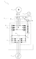
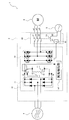
図1に示すように、本実施形態の過電圧保護システム1は、回転型のモータ2(回転電機)と、モータ2に接続される過電圧保護装置3とを有する。
モータ2は、3相(例えばU,V,W相)交流電力により駆動される、いわゆる3相交流モータとして構成されている。なお、モータ2は、3相交流電力により駆動される3相交流モータとして構成される場合に限定されるものではなく、単相交流電力により駆動される、いわゆる単相交流モータ等として構成されてもよい。このモータ2は、固定子、及び、固定子に対し回転自在に支持された回転子(いずれも図示せず)を有し、回転子が固定子に対し回転することで、回転子に結合されたシャフト(図示せず)を回転させ、回転力を出力する。詳細は図示していないが、固定子は、巻線(図示せず)を有する電機子として構成され、回転子は、磁界を発生する磁石(図示せず)を有する界磁として構成されている。なお、固定子が磁石を有する界磁として構成され、回転子が巻線を有する電機子として構成されてもよい。
過電圧保護装置3は、直流電力を交流電力に変換するインバータ装置10(電力変換装置)と、電磁開閉器20(開閉器、電力変換装置の交流変換部と回転電機との間の接続を遮断する手段)とを有する。
インバータ装置10は、コンバータ部11(直流電流の入力部)と、コンデンサ12(第1コンデンサ、正側直流母線と負側直流母線との間の電圧の立ち上がりを抑制する手段)と、インバータ部13(交流変換部)と、異常検出部14(電力変換装置及び回転電機のうち少なくとも一方の異常を検出する手段)とを有する。
コンバータ部11は、6つのダイオードで構成され、3相交流電源4から供給される3相(例えばR,S,T相)交流電力を整流し、正側直流母線である直流バスP、及び、負側直流母線である直流バスNへ直流電力を供給する。なお、コンバータ部11は、6つのダイオードで構成される場合に限定されるものではなく、他の構成でもよい。また、コンバータ部11へ交流電力を供給する交流電源としては、3相交流電力を供給する3相交流電源4に限定されるものではなく、単相交流電力を供給する単相交流電源等でもよい。また、インバータ装置10へ電力を供給する電源としては、交流電力を供給する交流電源に限定されるものではなく、直流電力を供給する直流電源でもよい。インバータ装置10へ電力を供給する電源が直流電源である場合には、コンバータ部11は必ずしも必要ではない。
コンデンサ12は、直流バスP,N間に接続され、静電容量により直流バスP,N間の電荷を吸収したり放出する。
インバータ部13は、直流バスP,Nに接続され、6つのスイッチング素子と、6つのスイッチング素子にそれぞれ逆並列接続された6つの還流ダイオードとで構成されている。なお、インバータ部13は、6つのスイッチング素子及び6つの還流ダイオードで構成される場合に限定されるものではなく、他の構成でもよい。このインバータ部13は、直流電力を3相(例えばU,V,W相)交流電力に変換し、モータ2へ供給する。
異常検出部14は、インバータ装置10の駆動中のインバータ装置10及びモータ2の少なくとも一方の異常を検出し、対応する異常検出信号を電磁開閉器20の開閉スイッチ25(後述)へ出力する。インバータ装置10及びモータ2のうち少なくとも一方の異常時には、直流バスP,N間に印加されるモータ2からの誘起電圧(逆起電圧)がインバータ装置10の耐圧を超える過電圧によって、インバータ装置10に悪影響が及ぶおそれがある。インバータ装置10及びモータ2のうち少なくとも一方の異常としては、種々挙げられ、特に限定されるものではない。但し、以下では、説明の便宜上、インバータ装置10及びモータ2のうち少なくとも一方の異常が、予め想定されたトルクの範囲を逸脱するトルク異常(過トルク)、予め想定された速度の範囲を逸脱する速度異常(過速度)、及び、予め想定された速度偏差の範囲を逸脱する速度偏差異常のうち少なくとも1つである場合について説明する。異常検出部14は、上記過トルクを検出した場合には、対応する異常検出信号である過トルク検出信号、上記過速度を検出した場合には、対応する異常検出信号である過速度検出信号、上記速度偏差異常を検出した場合には、対応する異常検出信号である速度偏差異常検出信号を、電磁開閉器20の開閉スイッチ25(後述)へ出力する。なお、この例では、上記のように、インバータ装置10及びモータ2のうち少なくとも一方の異常が過トルク、過速度、及び、速度偏差異常のうち少なくとも1つであると仮定しているので、異常検出部14が過トルク検出信号、過速度検出信号、及び速度偏差異常検出信号のいずれか1つを出力する場合について説明するが、異常検出部14が出力する異常検出信号の種類は、上記信号に限定されるものではない。
電磁開閉器20は、3つの接点21~23と、単相交流電源5から単相交流電力が供給される電磁コイル24と、開閉スイッチ25とを有する。なお、電磁コイル24へ電力を供給する電源としては、単相交流電力を供給する単相交流電源5に限定されるものではなく、直流電力を供給する直流電源等でもよい。
接点21~23は、インバータ装置10のインバータ部13とモータ2との間の接続路w1~w3にそれぞれ設けられている。これら接点21~23は、インバータ装置10の通常駆動時、つまり過トルク検出信号、過速度検出信号、及び速度偏差異常検出信号のいずれもが開閉スイッチ25に入力されていない場合に、閉じ状態となることで、インバータ装置10とモータ2とを接続し、3相交流電力がモータ2へ供給されるようにしている。
開閉スイッチ25は、電磁コイル24及び単相交流電源5に接続されたバスb1,b2のうちバスb1(又はバスb2でもよい)に設けられている。この開閉スイッチ25は、インバータ装置10の通常駆動時、つまり過トルク検出信号、過速度検出信号、及び速度偏差異常検出信号のいずれもが入力されていない場合に、開き状態となることで、単相交流電源5からの電流が電磁コイル24に流れない(電磁コイル24が導通されない)ようにしている。
このような電磁開閉器20では、インバータ装置10の駆動中に過トルク、過速度、及び速度偏差異常のうち少なくとも1つが生じ、過トルク検出信号、過速度検出信号、及び速度偏差異常検出信号のうち少なくとも1つが開閉スイッチ25に入力された場合に、開閉スイッチ25が閉じ動作して閉じ状態となることで、単相交流電源5からの電流が電磁コイル24に流れる。すると、電磁開閉器20では、接点21~23が開き動作して開き状態となることで、インバータ装置10とモータ2との接続を遮断する(切り離す)。なお、この例では、電磁開閉器20によりインバータ装置10とモータ2との接続を遮断する場合について説明するが、電磁開閉器20以外の開閉器によりインバータ装置10とモータ2との接続を遮断してもよい。ところで、電磁開閉器20がインバータ装置10とモータ2との接続を遮断完了するまでの間には、所定の時間が必要である。
本実施形態では、過トルク検出信号、過速度検出信号、及び速度偏差異常検出信号のうち少なくとも1つが電磁開閉器20の開閉スイッチ25に入力されると、電磁開閉器20がインバータ装置10とモータ2との接続を遮断開始する。そして、電磁開閉器20がインバータ装置10とモータ2との接続を遮断完了するまでの所定の時間が経過するまでの間、コンデンサ12が直流バスP,N間の電荷を吸収する。これにより、コンデンサ12がモータ2からの誘起電圧による直流バスP,N間の電圧の立ち上がりを抑制する。
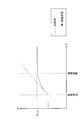
以下、図2を参照しつつ、直流バスP,N間に印加されるモータ2からの誘起電圧の変化について説明する。図2には、横軸を時間t、縦軸を直流バスP,N間に印加される電圧Vとしたグラフを示している。
図2に示すグラフでは、インバータ装置10の駆動中に過トルク、過速度、及び速度偏差異常のうち少なくとも1つが生じ、モータ2からの誘起電圧により直流バスP,N間の電圧Vが時間tの経過に伴い上昇する状況を示している。
このとき、電磁開閉器20及びコンデンサ12が設けられていない比較例の場合には、直流バスP,N間の電圧Vが時間tの経過に伴い上昇し、やがて直流バスP,N間の電圧Vがインバータ装置10の耐圧Vmaxを超える過電圧状態となっている。
一方、本実施形態の場合には、電磁開閉器20によりインバータ装置10とモータ2との接続の遮断が開始された後、直流バスP,N間の電圧Vが時間tの経過に伴い上昇するが、コンデンサ12により直流バスP,N間の電荷が吸収されることで、直流バスP,N間の電圧Vの上昇が上記比較例よりも遅く(緩やかに)なっている。そして、直流バスP,N間の電圧Vがインバータ装置10の耐圧Vmaxを超える過電圧となる前に、電磁開閉器20によりインバータ装置10とモータ2との接続の遮断が完了されることで、やがて直流バスP,N間の電圧Vが一定となっている。
以上説明したように、本実施形態の過電圧保護装置3においては、異常検出部14と電磁開閉器20とが備えられる。インバータ装置10の駆動中に異常が生じた場合、異常検出部14からの異常検出信号に応じて電磁開閉器20の接点21~23を開き動作させることで、インバータ装置10とモータ2との接続を切り離すことができる。
ここで、電磁開閉器20がインバータ装置10とモータ2との接続を遮断完了するまでの間には、所定の時間が必要である。これに対応して、本実施形態においては、直流バスP,N間にコンデンサ12が接続されている。これにより、上記所定の時間が経過するまでの間は、コンデンサ12が直流バスP,N間の電荷を吸収することで、モータ2からの誘起電圧による直流バスP,N間の電圧の立ち上がりを抑制することができる。
以上の結果、本実施形態によれば、モータ2からの誘起電圧による過電圧によってインバータ装置10に悪影響が及ぶのを確実に防止することができる。
また、本実施形態では特に、電磁開閉器20の接点21~23が、異常検出部14からの異常検出信号に応じて開き動作する。異常検出部14からの異常検出信号に応じて電磁開閉器20の接点21~23を開き動作させることで、インバータ装置10とモータ2との接続を確実に切り離すことができる。
また、本実施形態では特に、異常検出部14が、過トルク検出信号、過速度検出信号、及び速度偏差異常検出信号のうち少なくとも1つを出力する。これにより、インバータ装置10やモータ2において、予め想定されたトルクや速度、速度偏差の範囲を逸脱するような状況が生じた場合、これに対応して電磁開閉器20の接点21~23を確実に開き動作させることができる。
<第2実施形態>
次に、図3及び図4を参照しつつ、第2実施形態について説明する。なお、本実施形態において、上記第1実施形態と同様の部分には同符号を付し、適宜説明を省略する。
次に、図3及び図4を参照しつつ、第2実施形態について説明する。なお、本実施形態において、上記第1実施形態と同様の部分には同符号を付し、適宜説明を省略する。
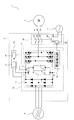
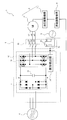
図3に示すように、本実施形態の過電圧保護システム1は、モータ2と、過電圧保護装置3とを有する。
モータ2は、上記第1実施形態と同様である。
過電圧保護装置3は、インバータ装置10と、電磁開閉器20と、インバータ装置10の外部に設けられた電圧検出器30とを有する。なお、電圧検出器30は、インバータ装置10の内部に設けられてもよい。
インバータ装置10は、コンバータ部11と、コンデンサ12と、インバータ部13と、異常検出部14と、コンデンサ15(第2コンデンサ)と、抵抗16と、開閉スイッチ17とを有する。
コンバータ部11、コンデンサ12、インバータ部13、及び異常検出部14は、上記第1実施形態と同様である。
コンデンサ15及び抵抗16は、直流バスP,N間にコンデンサ12と並列に接続される。コンデンサ15は、静電容量により直流バスP,N間の電荷を吸収したり放出する。抵抗16は、電力を消費する。
開閉スイッチ17は、コンデンサ15及び抵抗16と直流バスP(又は直流バスNでもよい)との間に設けられている。この開閉スイッチ17は、インバータ装置10の通常駆動時、具体的には後述するスイッチ制御信号が入力されていない場合に、開き状態となることで、直流バスP,N間に、コンデンサ15及び抵抗16が接続されない(コンデンサ15及び抵抗16が導通されない)ようにしている。
電磁開閉器20は、上記第1実施形態と同様である。
電圧検出器30は、電圧検出部31と、スイッチ制御部32とを備える。
電圧検出部31は、直流バスP,N間の電圧を検出する。
スイッチ制御部32は、電圧検出部31により検出された直流バスP,N間の電圧値に応じて、インバータ装置10の開閉スイッチ17へ制御信号(以下適宜「スイッチ制御信号」という)を出力する。具体的には、スイッチ制御部32は、電圧検出部31により検出された直流バスP,N間の電圧値が所定の電圧しきい値を超えた場合に、開閉スイッチ17へスイッチ制御信号を出力する。
上記開閉スイッチ17は、直流バスP,N間の電圧値が所定の電圧しきい値を超え、スイッチ制御信号が入力された場合に、閉じ動作して閉じ状態となることで、直流バスP,N間に、コンデンサ15及び抵抗16をコンデンサ12と並列に接続する。
本実施形態では、過トルク検出信号、過速度検出信号、及び速度偏差異常検出信号のうち少なくとも1つが電磁開閉器20の開閉スイッチ25に入力されると、電磁開閉器20がインバータ装置10とモータ2との接続を遮断開始する。そして、電磁開閉器20がインバータ装置10とモータ2との接続を遮断完了するまでの所定の時間が経過するまでの間、コンデンサ12が直流バスP,N間の電荷を吸収する。これにより、コンデンサ12がモータ2からの誘起電圧による直流バスP,N間の電圧の立ち上がりを抑制する。またこの間に、電圧検出部31が検出した直流バスP,N間の電圧値が所定の電圧しきい値を超えると、スイッチ制御部32が開閉スイッチ17へスイッチ制御信号を出力する。これにより、開閉スイッチ17が、閉じ動作して閉じ状態となることで、直流バスP,N間に、コンデンサ15及び抵抗16をコンデンサ12と並列に接続する。すると、コンデンサ12,15が協働して、それらの合計容量により直流バスP,N間の電荷を吸収することで、モータ2からの誘起電圧による直流バスP,N間の電圧の立ち上がりを抑制する。またこれと共に、抵抗16がコンデンサ12に蓄えられた電荷を消費することで、直流バスP,N間の電圧を降下させる。なお、直流バスP,N間の電圧が一定値まで降下すると、スイッチ制御部32が開閉スイッチ17へ制御信号を出力する。これにより、開閉スイッチ17が、開き動作して開き状態となることで、上記直流バスP,N間へのコンデンサ15及び抵抗16の接続が解除される。
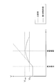
以下、図4を参照しつつ、直流バスP,N間に印加されるモータ2からの誘起電圧の変化について説明する。図4には、横軸を時間t、縦軸を直流バスP,N間に印加される電圧Vとしたグラフを示している。
図4に示すグラフでは、インバータ装置10の駆動中に過トルク、過速度、及び速度偏差異常のうち少なくとも1つが生じ、モータ2からの誘起電圧により直流バスP,N間の電圧Vが時間tの経過に伴い上昇する状況を示している。
このとき、電磁開閉器20、コンデンサ12,15、及び抵抗16が設けられていない比較例の場合には、直流バスP,N間の電圧Vが時間tの経過に伴い上昇し、やがて直流バスP,N間の電圧Vがインバータ装置10の耐圧Vmaxを超える過電圧状態となっている。
一方、本実施形態の場合には、電磁開閉器20によりインバータ装置10とモータ2との接続の遮断が開始された後、直流バスP,N間の電圧Vが時間tの経過に伴い上昇するが、直流バスP,N間の電圧値が所定の電圧しきい値Vsを超えると、直流バスP,N間に、コンデンサ15及び抵抗16がコンデンサ12と並列に接続される。これにより、コンデンサ12,15により直流バスP,N間の電荷が吸収されると共に、抵抗16によりコンデンサ12に蓄えられた電荷が消費されることで、直流バスP,N間の電圧Vの上昇が上記比較例よりも遅く(緩やかに)なっている。そして、直流バスP,N間の電圧Vがインバータ装置10の耐圧Vmaxを超える過電圧となる前に、電磁開閉器20によりインバータ装置10とモータ2との接続の遮断が完了されることで、やがて直流バスP,N間の電圧Vが一定値まで下降している。
以上説明した本実施形態によれば、上記第1実施形態と同様、モータ2からの誘起電圧による過電圧によってインバータ装置10に悪影響が及ぶのを確実に防止することができる。
また、本実施形態では特に、コンデンサ15及び抵抗16と、開閉スイッチ17とが設けられる。これにより、開閉スイッチ17を閉じ状態とすることで、直流バスP,N間に、上記コンデンサ12に加え、コンデンサ15及び抵抗16を並列接続することができる。これにより、電磁開閉器20がインバータ装置10とモータ2との接続を遮断完了するまでの所定の時間が経過するまでの間に、コンデンサ12,15が協働してそれらの合計容量により電荷を吸収することで、直流バスP,N間の電圧の立ち上がりをさらに遅くすることができる。またこれと共に、上記所定の時間が経過するまでの間に、コンデンサ12が溜め込んだ電荷を抵抗16が消費することで、直流バスP,N間の電圧を積極的に降下させることができる。
また、本実施形態では特に、電圧検出器30のスイッチ制御部32が、直流バスP,N間の電圧値に応じて、開閉スイッチ17を閉じ状態とする。これにより、直流バスP,N間に、コンデンサ12に加えてコンデンサ15及び抵抗16を並列接続することで、モータ2からの誘起電圧による過電圧によってインバータ装置10に悪影響が及ぶのを確実に防止することができる。また、直流バスP,N間の電圧値が高くなっていないインバータ装置10の通常駆動時には、開閉スイッチ17を開き状態とすることで、無駄な損失が生じるのを回避することができる。さらに、本実施形態では、コンデンサ15及び抵抗16が設けられており、上記のように開閉スイッチ17が閉じ状態となった後、直流バスP,N間の電圧値が再び一定値まで降下したとき、開閉スイッチ17が開き状態となって、コンデンサ15が溜め込んだ電荷を抵抗16で消費することができる。
<第3実施形態>
次に、図5を参照しつつ、第3実施形態について説明する。なお、本実施形態において、上記第1及び第2実施形態と同様の部分には同符号を付し、適宜説明を省略する。
次に、図5を参照しつつ、第3実施形態について説明する。なお、本実施形態において、上記第1及び第2実施形態と同様の部分には同符号を付し、適宜説明を省略する。
図5に示すように、本実施形態の過電圧保護システム1は、モータ2と、過電圧保護装置3とを有する。
モータ2は、上記第1実施形態と同様である。
過電圧保護装置3は、インバータ装置10と、電磁開閉器20とを有する。
インバータ装置10は、コンバータ部11と、コンデンサ12と、インバータ部13と、異常検出部14′(スイッチ制御部、電力変換装置及び回転電機のうち少なくとも一方の異常を検出する手段)と、コンデンサ15と、抵抗16と、開閉スイッチ17′とを有する。
コンバータ部11、コンデンサ12、インバータ部13は、上記第1実施形態と同様である。
異常検出部14′は、前述の異常検出部14と同様、前述の過トルクを検出した場合には、対応する過トルク検出信号、前述の過速度を検出した場合には、対応する過速度検出信号、前述の速度偏差異常を検出した場合には、対応する速度偏差異常検出信号を、電磁開閉器20の開閉スイッチ25と開閉スイッチ17′とへ出力する。
コンデンサ15及び抵抗16は、上記第2実施形態と同様である。
開閉スイッチ17′は、コンデンサ15及び抵抗16と直流バスP(又は直流バスNでもよい)との間に設けられている。この開閉スイッチ17′は、インバータ装置10の通常駆動時、具体的には過トルク検出信号、過速度検出信号、及び速度偏差異常検出信号のいずれもが入力されていない場合に、開き状態となることで、直流バスP,N間に、コンデンサ15及び抵抗16が接続されない(コンデンサ15及び抵抗16が導通されない)ようにしている。また、開閉スイッチ17′は、インバータ装置10の駆動中に過トルク、過速度、及び速度偏差異常のうち少なくとも1つが生じ、過トルク検出信号、過速度検出信号、及び速度偏差異常検出信号のうち少なくとも1つが入力された場合に、閉じ動作して閉じ状態となることで、直流バスP,N間に、コンデンサ15及び抵抗16をコンデンサ12と並列に接続する。
電磁開閉器20は、上記第1実施形態と同様である。
本実施形態では、過トルク検出信号、過速度検出信号、及び速度偏差異常検出信号のうち少なくとも1つが電磁開閉器20の開閉スイッチ25に入力されると、電磁開閉器20がインバータ装置10とモータ2との接続を遮断開始する。またこれと共に、過トルク検出信号、過速度検出信号、及び速度偏差異常検出信号のうち少なくとも1つが開閉スイッチ17′に入力されると、開閉スイッチ17′が、閉じ動作して閉じ状態となることで、直流バスP,N間に、コンデンサ15及び抵抗16をコンデンサ12と並列に接続する。そして、電磁開閉器20がインバータ装置10とモータ2との接続を遮断完了するまでの所定の時間が経過するまでの間、コンデンサ12,15が協働して、それらの合計容量により直流バスP,N間の電荷を吸収することで、モータ2からの誘起電圧による直流バスP,N間の電圧の立ち上がりを抑制する。またこれと共に、抵抗16がコンデンサ12に蓄えられた電荷を消費することで、直流バスP,N間の電圧を降下させる。
以上説明した本実施形態によれば、上記第1及び第2実施形態と同様、モータ2からの誘起電圧による過電圧によってインバータ装置10に悪影響が及ぶのを確実に防止することができる。また、上記第2実施形態と同様、電磁開閉器20がインバータ装置10とモータ2との接続を遮断完了するまでの所定の時間が経過するまでの間に、コンデンサ12,15が協働してそれらの合計容量により電荷を吸収することで、直流バスP,N間の電圧の立ち上がりをさらに遅くすることができる。またこれと共に、上記所定の時間が経過するまでの間に、コンデンサ12が溜め込んだ電荷を抵抗16が消費することで、直流バスP,N間の電圧を積極的に降下させることができる。
また、本実施形態では特に、異常検出部14′が、異常検出信号に応じて、開閉スイッチ17′を閉じ状態とする。これにより、上記第2実施形態と同様、直流バスP,N間に、コンデンサ12に加えてコンデンサ15及び抵抗16を並列接続することで、モータ2からの誘起電圧による過電圧によってインバータ装置10に悪影響が及ぶのを確実に防止することができる。また、異常検出信号が出力されていないインバータ装置10の通常駆動時には、開閉スイッチ17′を開き状態とすることで、無駄な損失が生じるのを回避することができる。
<第4実施形態>
次に、図6~図8を参照しつつ、第4実施形態について説明する。なお、本実施形態において、上記第1~第3実施形態と同様の部分には同符号を付し、適宜説明を省略する。
次に、図6~図8を参照しつつ、第4実施形態について説明する。なお、本実施形態において、上記第1~第3実施形態と同様の部分には同符号を付し、適宜説明を省略する。
図6に示すように、本実施形態の過電圧保護システム1は、可変界磁モータ装置6(回転電機)と、過電圧保護装置3と、界磁調整機構8(界磁調整部)とを有する。
可変界磁モータ装置6は、回転型のモータ2′と、油圧駆動機構7(可変界磁機構、機械駆動機構)とを有する。
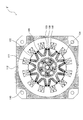
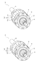
モータ2′は、3相交流モータとして構成されている。なお、モータ2′は、3相交流モータとして構成される場合に限定されるものではなく、単相交流モータ等として構成されてもよい。図7及び図8(a)(b)に示すように、このモータ2′は、固定子110と、固定子110に対し回転自在に支持された回転子120とを有し、回転子120が固定子110に対し回転することで、回転子120に結合されたシャフト130を回転させ、回転力を出力する。
固定子110は、空芯コイルで構成された巻線111と、鉄心112とを備え、電機子として構成されている。
回転子120は、磁界を発生する磁極部121と、鉄心122とを備え、界磁として構成されている。
磁極部121は、軸方向に3分割されており、シャフト130の外周に固定された中央の磁極部121aに対し負荷側磁極部121b及び反負荷側磁極部121cが相対的に回動可能となっている。各磁極部121a,121b,121cは、鉄心122に設けられた略V字形状の装着孔に磁界を発生する磁石123が着磁方向を対面又は背面としつつ装着されることで構成されている。
可変界磁モータ装置6に備えられた油圧制御部(図示せず)は、シャフト130に設けられた増磁側油導入路132及び減磁側油導入路133を通して、シャフト130に設けられた油圧室134に油圧を供給する。これにより、油圧制御部は、油圧室134に装着された移動自在の受圧プレート150を円周方向に移動させ、受圧プレート150に一体に締結された負荷側界極部121b及び反負荷側磁極部121cを中央の磁極部121aに対し相対的に回動させることで、固定子110と回転子120との間を鎖交する鎖交磁束を変化させる。なお、油圧駆動機構7は、上記油圧制御部、増磁側油導入路132、減磁側油導入路133、油圧室134、受圧プレート150等により構成されている。つまり、油圧駆動機構7は、油圧制御部の制御により油圧室134に油圧を供給することで、負荷側界極部121b及び反負荷側磁極部121cを中央の磁極部121aに対し相対的に回動させるというような、回転子120に対する機械的な調整により、鎖交磁束を変化させる。
すなわち、鎖交磁束を弱めるときには、油圧制御部の制御により減磁側油導入路133から油圧室134へ高圧のオイルが導入され、受圧プレート150が円周方向一方側へ移動することで、中央の磁極部121aに対する負荷側磁極部121b及び反負荷側磁極部121cの相対角度が増加される。図8(a)に示す状態では、負荷側磁極部121b及び反負荷側磁極部121cは、中央の磁極部121aに対し相対的に大きく回動し、磁極同士が相殺して鎖交磁束は弱くなっている。
一方、鎖交磁束を強めるときには、油圧制御部の制御により増磁側油導入路132から油圧室134へ高圧のオイルが導入され、受圧プレート150が円周方向他方側へ移動することで、中央の磁極部121aに対する負荷側磁極部121b及び反負荷側磁極部121cの相対角度が減少される。図8(b)に示す状態では、負荷側磁極部121b及び反負荷側磁極部121cは、中央の磁極部121aと磁極を並べ、鎖交磁束は最も強くなっている。
過電圧保護装置3は、インバータ装置10と、電磁開閉器20とを有する。
インバータ装置10は、コンバータ部11と、コンデンサ12と、インバータ部13と、異常検出部14″(電力変換装置及び回転電機のうち少なくとも一方の異常を検出する手段)とを有する。
コンバータ部11、コンデンサ12、インバータ部13は、上記第1実施形態と同様である。
異常検出部14″は、前述の異常検出部14と同様、前述の過トルクを検出した場合には、対応する過トルク検出信号、前述の過速度を検出した場合には、対応する過速度検出信号、前述の速度偏差異常を検出した場合には、対応する速度偏差異常検出信号を、電磁開閉器20の開閉スイッチ25と界磁調整機構8とへ出力する。
電磁開閉器20は、上記第1実施形態と同様である。
界磁調整機構8は、過トルク検出信号、過速度検出信号、及び速度偏差異常検出信号のいずれかが入力された場合に、油圧駆動機構7の油圧制御部に対し、界磁率を弱めるか若しくは0にする制御信号を出力する。界磁率は、中央の磁極部121aに対し負荷側磁極部121b及び反負荷側磁極部121cが相対的に回動した状態での誘起電圧定数の割合である。
上記油圧駆動機構7の油圧制御部は、界磁調整機構8から入力された制御信号に応じて、油圧室134に供給する油圧を制御し、中央の磁極部121aに対する負荷側界極部121b及び反負荷側磁極部121cの相対的な回動を制御する。これにより、油圧駆動機構7は、鎖交磁束を変化させて界磁率を弱めるか若しくは0に調整することで、モータ2′から生じる誘起電圧を低減する。但し、上記のように油圧駆動機構7が鎖交磁束を変化させるとき、磁束変化の完了までに比較的大きな応答遅れが生じる。
本実施形態では、過トルク検出信号、過速度検出信号、及び速度偏差異常検出信号のうち少なくとも1つが電磁開閉器20の開閉スイッチ25に入力されると、電磁開閉器20がインバータ装置10とモータ2′との接続を遮断開始する。またこれと共に、過トルク検出信号、過速度検出信号、及び速度偏差異常検出信号のうち少なくとも1つが界磁調整機構8に入力されると、界磁調整機構8が油圧駆動機構7の油圧制御部に対し制御信号を出力する。これにより、油圧駆動機構7が鎖交磁束を変化させることによる界磁率の調整を開始するが、界磁率の調整が完了するまでに比較的大きな時間を有する。そして、電磁開閉器20がインバータ装置10とモータ2′との接続を遮断完了するまでの所定の時間が経過するまでの間、コンデンサ12が直流バスP,N間の電荷を吸収する。これにより、コンデンサ12がモータ2′からの誘起電圧による直流バスP,N間の電圧の立ち上がりを抑制する。
以上説明した本実施形態によれば、上記第1~第3実施形態と同様、モータ2′からの誘起電圧による過電圧によってインバータ装置10に悪影響が及ぶのを確実に防止することができる。
また、本実施形態では特に、界磁調整機構8が、異常検出部14″からの異常検出信号に応じて、可変界磁モータ装置6の油圧駆動機構7の油圧制御部に対し、界磁率を弱める制御信号を出力する。これにより、モータ2′から生じる誘起電圧を低減することができるので、インバータ装置10とモータ2′とが遮断完了するまでの間、直流バスP,N間の電圧の立ち上がりをさらに確実に抑制することができる。
また、本実施形態の過電圧保護システム1では特に、可変界磁モータ装置6が油圧駆動機構7を備える。これにより、異常検出部14″から異常検出信号が出力された際には、これに応じて油圧駆動機構7が鎖交磁束を変化させ、モータ2′から生じる誘起電圧を低減することができる。この結果、インバータ装置10とモータ2′とが遮断完了するまでの間、直流バスP,N間の電圧の立ち上がりをさらに確実に抑制することができる。
また、本実施形態では特に、油圧駆動機構7が、回転子120に対する機械的な調整により鎖交磁束を変化させる。このようにして誘起電圧を低減するために油圧駆動機構7が鎖交磁束を変化させるとき、磁束変化の完了までに比較的大きな応答遅れが生じる。したがって、前述したような、コンデンサ12による直流バスP,N間の電圧の立ち上がり抑制機能が特に効果的である。
また、本実施形態では特に、界磁調整機構8が、油圧駆動機構7の油圧制御部に対し、界磁率を弱めるか若しくは0にする制御信号を出力する。これにより、異常検出部14″から異常検出信号が出力された際には、モータ2′から生じる誘起電圧を確実に低減することができる。
<第5実施形態>
次に、図9を参照しつつ、第5実施形態について説明する。なお、本実施形態において、上記第1~第4実施形態と同様の部分には同符号を付し、適宜説明を省略する。
次に、図9を参照しつつ、第5実施形態について説明する。なお、本実施形態において、上記第1~第4実施形態と同様の部分には同符号を付し、適宜説明を省略する。
図9に示すように、本実施形態の過電圧保護システム1は、可変界磁モータ装置6と、過電圧保護装置3と、界磁調整機構8とを有する。
可変界磁モータ装置6は、上記第4実施形態と同様である。
過電圧保護装置3は、インバータ装置10を有する。
インバータ装置10は、コンバータ部11と、コンデンサ12と、インバータ部13と、異常検出部14A(電力変換装置及び回転電機のうち少なくとも一方の異常を検出する手段)とを有する。
コンバータ部11、コンデンサ12、インバータ部13は、上記第1実施形態と同様である。
異常検出部14Aは、前述の異常検出部14と同様、前述の過トルクを検出した場合には、対応する過トルク検出信号、前述の過速度を検出した場合には、対応する過速度検出信号、前述の速度偏差異常を検出した場合には、対応する速度偏差異常検出信号を、界磁調整機構8へ出力する。
界磁調整機構8は、上記第4実施形態と同様である。
本実施形態では、過トルク検出信号、過速度検出信号、及び速度偏差異常検出信号のうち少なくとも1つが界磁調整機構8に入力されると、界磁調整機構8が油圧駆動機構7の油圧制御部に対し制御信号を出力する。これにより、油圧駆動機構7が鎖交磁束を変化させることによる界磁率の調整を開始するが、界磁率の調整が完了するまでに比較的大きな時間を有する。そして、界磁率の調整が完了するまでの間、コンデンサ12が直流バスP,N間の電荷を吸収する。これにより、コンデンサ12がモータ2′からの誘起電圧による直流バスP,N間の電圧の立ち上がりを抑制する。
以上説明したように、本実施形態においては、界磁調整機構8が、異常検出部14Aからの異常検出信号に応じて、可変界磁モータ装置6の油圧駆動機構7の油圧制御部に対し、界磁率を弱める制御信号を出力する。これにより、モータ2′から生じる誘起電圧を低減することができる。
ここで、油圧駆動機構7により誘起電圧を低減するとき、誘起電圧の低減までに比較的大きな応答遅れが生じる。これに対応して、本実施形態においては、直流バスP,N間にコンデンサ12が接続されている。これにより、上記誘起電圧が低減されるまでの間は、コンデンサ12が直流バスP,N間の電荷を吸収することで、モータ2からの誘起電圧による直流バスP,N間の電圧の立ち上がりを抑制することができる。
以上の結果、本実施形態によれば、モータ2′からの誘起電圧による過電圧によってインバータ装置10に悪影響が及ぶのを確実に防止することができる。
<変形例等>
なお、実施の形態は、上記内容に限られるものではなく、その趣旨及び技術的思想を逸脱しない範囲内で種々の変形が可能である。
なお、実施の形態は、上記内容に限られるものではなく、その趣旨及び技術的思想を逸脱しない範囲内で種々の変形が可能である。
すなわち、上記第1~第5実施形態では、インバータ装置10が異常検出部14,14′,14″,14Aを備える場合について説明したが、これに限定されるものではない。例えば、インバータ装置10の外部に、異常検出部が設けられてもよい。
また、上記第2実施形態では、インバータ装置10が、直流バスP,N間に、コンデンサ12と並列に接続されるコンデンサ15及び抵抗16を備える場合について説明したが、これに限定されるものではない。例えば、インバータ装置10が、直流バスP,N間に、コンデンサ12と並列に接続されるコンデンサ15及び抵抗16うちのいずれか一方を備える場合についても適用可能である。
また、上記第4及び第5実施形態では、可変界磁モータ装置6が油圧駆動機構7を備える場合について説明したが、これに限定されるものではない。例えば、可変界磁モータ装置6は、油圧駆動機構7が鎖交磁束を変化させる仕組みとは異なる回転子に対する機械的な調整により、鎖交磁束を変化させる機構(可変界磁機構、機械駆動機構)を備えてもよい。さらには、可変界磁モータ装置6は、回転子に対する機械的以外の調整(例えば電気的な調整等)により、鎖交磁束を変化させる機構(可変界磁機構)を備えてもよい。
また、上記第1~第5実施形態では、過電圧保護装置3が直流電力を交流電力に変換するインバータ装置10を備える場合について説明したが、これに限定されるものではない。例えば、過電圧保護装置3が、電力変換装置として、交流電力から直流電力に変換するコンバータ装置やパワーコンディショナ等を備える場合にも適用可能である。
また、上記第1~第5実施形態では、過電圧保護装置3が交流電力に駆動する交流モータであるモータ2,2′を備える場合について説明したが、これに限定されるものではない。例えば、過電圧保護装置3が、直流電力に駆動する直流モータ(回転電機)を備える場合にも適用可能である。
また、上記第1~第5実施形態では、過電圧保護システム1が電動機であるモータ2,2′を備える場合について説明したが、これに限定されるものではない。例えば、過電圧保護システム1が、発電機(回転電機)を備える場合にも適用可能である。
また、以上既に述べた以外にも、上記各実施形態や各変形例等による手法を適宜組み合わせて利用してもよい。
その他、一々例示はしないが、上記各実施形や各変形例等は、その趣旨を逸脱しない範囲内において、種々の変更が加えられて実施されるものである。
1 過電圧保護システム
2 モータ(回転電機)
3 過電圧保護装置
6 可変制御モータ装置(回転電機)
7 油圧駆動機構(可変界磁機構、機械駆動機構)
8 界磁調整機構(界磁調整機構)
10 インバータ装置(電力変換装置)
11 コンバータ部(直流電流の入力部)
12 コンデンサ(第1コンデンサ、正側直流母線と負側直流母線との間の電圧の立ち上がりを抑制する手段)
13 インバータ部(交流変換部)
14 異常検出部(電力変換装置及び回転電機のうち少なくとも一方の異常を検出する手段)
14′ 異常検出部(スイッチ制御部、電力変換装置及び回転電機のうち少なくとも一方の異常を検出する手段)
14″ 異常検出部(電力変換装置及び回転電機のうち少なくとも一方の異常を検出する手段)
14A 異常検出部(電力変換装置及び回転電機のうち少なくとも一方の異常を検出する手段)
15 コンデンサ(第2コンデンサ)
16 抵抗
17 開閉スイッチ
20 電磁開閉器(開閉器、電力変換装置の交流変換部と回転電機との間の接続を遮断する手段)
32 スイッチ制御部
110 固定子
120 回転子
N 直流バス(負側直流母線)
P 直流バス(正側直流母線)
w1~w3 接続路
2 モータ(回転電機)
3 過電圧保護装置
6 可変制御モータ装置(回転電機)
7 油圧駆動機構(可変界磁機構、機械駆動機構)
8 界磁調整機構(界磁調整機構)
10 インバータ装置(電力変換装置)
11 コンバータ部(直流電流の入力部)
12 コンデンサ(第1コンデンサ、正側直流母線と負側直流母線との間の電圧の立ち上がりを抑制する手段)
13 インバータ部(交流変換部)
14 異常検出部(電力変換装置及び回転電機のうち少なくとも一方の異常を検出する手段)
14′ 異常検出部(スイッチ制御部、電力変換装置及び回転電機のうち少なくとも一方の異常を検出する手段)
14″ 異常検出部(電力変換装置及び回転電機のうち少なくとも一方の異常を検出する手段)
14A 異常検出部(電力変換装置及び回転電機のうち少なくとも一方の異常を検出する手段)
15 コンデンサ(第2コンデンサ)
16 抵抗
17 開閉スイッチ
20 電磁開閉器(開閉器、電力変換装置の交流変換部と回転電機との間の接続を遮断する手段)
32 スイッチ制御部
110 固定子
120 回転子
N 直流バス(負側直流母線)
P 直流バス(正側直流母線)
w1~w3 接続路
Claims (11)
- 回転電機に接続される過電圧保護装置であって、
直流電流の入力部、前記入力部にそれぞれ接続された正側直流母線及び負側直流母線、前記正側直流母線及び前記負側直流母線に接続された交流変換部、前記正側直流母線と前記負側直流母線との間に接続された第1コンデンサ、を有する電力変換装置と、
前記電力変換装置の前記交流変換部と前記回転電機との間の接続路に設けられた開閉器と、
前記電力変換装置及び前記回転電機のうち少なくとも一方の異常検出信号を出力する異常検出部と、
を有することを特徴とする過電圧保護装置。 - 前記開閉器は、
前記異常検出部からの前記異常検出信号に応じて開き動作する
ことを特徴とする請求項1記載の過電圧保護装置。 - 前記異常検出部は、
過トルク検出信号、過速度検出信号、及び速度偏差異常検出信号のうち少なくとも1つを出力する
ことを特徴とする請求項1又は2記載の過電圧保護装置。 - 前記電力変換装置は、
前記正側直流母線と前記負側直流母線との間に前記第1コンデンサと並列に接続される、第2コンデンサ及び抵抗の少なくとも一方と、
前記第2コンデンサ及び前記抵抗の前記少なくとも一方と、前記正側直流母線若しくは前記負側直流母線との間に設けられた開閉スイッチと、
を備えることを特徴とする請求項1乃至3のいずれか1項記載の過電圧保護装置。 - 前記正側直流母線と前記負側直流母線との間の電圧値、若しくは、前記異常検出信号に応じて、前記開閉スイッチを閉じ動作させるスイッチ制御部を有する
ことを特徴とする請求項4記載の過電圧保護装置。 - 前記異常検出部からの前記異常検出信号に応じて、前記回転電機に対し、界磁率を弱める制御信号を出力する界磁調整部を備える
ことを特徴とする請求項1乃至5のいずれか1項記載の過電圧保護装置。 - 回転電機に接続される過電圧保護装置であって、
直流電流の入力部、前記入力部にそれぞれ接続された正側直流母線及び負側直流母線、前記正側直流母線及び前記負側直流母線に接続された交流変換部、前記正側直流母線と前記負側直流母線との間に接続されたコンデンサ、を有する電力変換装置と、
前記電力変換装置及び前記回転電機のうち少なくとも一方の異常検出信号を出力する異常検出部と、
前記異常検出部からの前記異常検出信号に応じて、前記回転電機に対し、界磁率を弱める制御信号を出力する界磁調整部と、
を有することを特徴とする過電圧保護装置。 - 回転電機に接続される過電圧保護装置であって、
直流電流の入力部、前記入力部にそれぞれ接続された正側直流母線及び負側直流母線、前記正側直流母線及び前記負側直流母線に接続された交流変換部、を有する電力変換装置と、
前記電力変換装置及び前記回転電機のうち少なくとも一方の異常を検出する手段と、
前記異常を検出する手段で前記少なくとも一方の異常が検出された場合に、前記正側直流母線と前記負側直流母線との間の電圧の立ち上がりを抑制する手段と、
前記異常を検出する手段で前記少なくとも一方の異常が検出された場合に、前記電力変換装置の前記交流変換部と前記回転電機との間の接続を遮断する手段と、
を有することを特徴とする過電圧保護装置。 - 請求項6記載の過電圧保護装置と、
回転子、固定子、前記回転子と前記固定子との間の鎖交磁束を変化させる可変界磁機構、を有する回転電機と、
を備えることを特徴とする過電圧保護システム。 - 前記可変磁界機構は、
前記回転子に対する機械的な調整により前記鎖交磁束を変化させる機械駆動機構である
ことを特徴とする請求項9記載の過電圧保護システム。 - 前記界磁調整部は、
前記可変界磁機構に対し、界磁率を弱めるか若しくは0にする制御信号を出力する
ことを特徴とする請求項9又は10記載の過電圧保護システム。
Priority Applications (2)
| Application Number | Priority Date | Filing Date | Title |
|---|---|---|---|
| PCT/JP2013/065724 WO2014196065A1 (ja) | 2013-06-06 | 2013-06-06 | 過電圧保護装置及び過電圧保護システム |
| JP2015521241A JPWO2014196065A1 (ja) | 2013-06-06 | 2013-06-06 | 過電圧保護装置及び過電圧保護システム |
Applications Claiming Priority (1)
| Application Number | Priority Date | Filing Date | Title |
|---|---|---|---|
| PCT/JP2013/065724 WO2014196065A1 (ja) | 2013-06-06 | 2013-06-06 | 過電圧保護装置及び過電圧保護システム |
Publications (1)
| Publication Number | Publication Date |
|---|---|
| WO2014196065A1 true WO2014196065A1 (ja) | 2014-12-11 |
Family
ID=52007739
Family Applications (1)
| Application Number | Title | Priority Date | Filing Date |
|---|---|---|---|
| PCT/JP2013/065724 Ceased WO2014196065A1 (ja) | 2013-06-06 | 2013-06-06 | 過電圧保護装置及び過電圧保護システム |
Country Status (2)
| Country | Link |
|---|---|
| JP (1) | JPWO2014196065A1 (ja) |
| WO (1) | WO2014196065A1 (ja) |
Cited By (3)
| Publication number | Priority date | Publication date | Assignee | Title |
|---|---|---|---|---|
| CN108134375A (zh) * | 2018-03-09 | 2018-06-08 | 核工业理化工程研究院 | 永磁同步电机控制电路的保护装置 |
| JP2019176559A (ja) * | 2018-03-27 | 2019-10-10 | 株式会社Subaru | 車両用電源装置 |
| US20250007276A1 (en) * | 2021-11-15 | 2025-01-02 | Jordi Chaves Garcia | Torque protection mechanism for brushless motors |
Citations (6)
| Publication number | Priority date | Publication date | Assignee | Title |
|---|---|---|---|---|
| JPH0919003A (ja) * | 1995-06-27 | 1997-01-17 | Honda Motor Co Ltd | 電動車両におけるコンデンサの劣化判定装置 |
| JP2003333862A (ja) * | 2002-05-15 | 2003-11-21 | Toshiba Corp | 電力変換装置 |
| WO2007072622A1 (ja) * | 2005-12-21 | 2007-06-28 | Honda Motor Co., Ltd. | 電動機 |
| WO2011104848A1 (ja) * | 2010-02-25 | 2011-09-01 | 三菱電機株式会社 | 電力変換装置 |
| WO2012105266A1 (ja) * | 2011-02-03 | 2012-08-09 | パナソニック株式会社 | モータ駆動装置 |
| JP2013046440A (ja) * | 2011-08-22 | 2013-03-04 | Yaskawa Electric Corp | 回転電機 |
-
2013
- 2013-06-06 WO PCT/JP2013/065724 patent/WO2014196065A1/ja not_active Ceased
- 2013-06-06 JP JP2015521241A patent/JPWO2014196065A1/ja active Pending
Patent Citations (6)
| Publication number | Priority date | Publication date | Assignee | Title |
|---|---|---|---|---|
| JPH0919003A (ja) * | 1995-06-27 | 1997-01-17 | Honda Motor Co Ltd | 電動車両におけるコンデンサの劣化判定装置 |
| JP2003333862A (ja) * | 2002-05-15 | 2003-11-21 | Toshiba Corp | 電力変換装置 |
| WO2007072622A1 (ja) * | 2005-12-21 | 2007-06-28 | Honda Motor Co., Ltd. | 電動機 |
| WO2011104848A1 (ja) * | 2010-02-25 | 2011-09-01 | 三菱電機株式会社 | 電力変換装置 |
| WO2012105266A1 (ja) * | 2011-02-03 | 2012-08-09 | パナソニック株式会社 | モータ駆動装置 |
| JP2013046440A (ja) * | 2011-08-22 | 2013-03-04 | Yaskawa Electric Corp | 回転電機 |
Cited By (4)
| Publication number | Priority date | Publication date | Assignee | Title |
|---|---|---|---|---|
| CN108134375A (zh) * | 2018-03-09 | 2018-06-08 | 核工业理化工程研究院 | 永磁同步电机控制电路的保护装置 |
| JP2019176559A (ja) * | 2018-03-27 | 2019-10-10 | 株式会社Subaru | 車両用電源装置 |
| JP7041567B2 (ja) | 2018-03-27 | 2022-03-24 | 株式会社Subaru | 車両用電源装置 |
| US20250007276A1 (en) * | 2021-11-15 | 2025-01-02 | Jordi Chaves Garcia | Torque protection mechanism for brushless motors |
Also Published As
| Publication number | Publication date |
|---|---|
| JPWO2014196065A1 (ja) | 2017-02-23 |
Similar Documents
| Publication | Publication Date | Title |
|---|---|---|
| JP5845429B2 (ja) | モータ | |
| JP4647684B2 (ja) | 電力変換装置 | |
| JP3091768B2 (ja) | 電圧調整器付きハイブリッド交流発電機 | |
| RU2410823C2 (ru) | Двигатель с поперечным потоком и турбодвигатель с двигателем с поперечным потоком такого рода | |
| JP5014437B2 (ja) | 励磁機と、送電系統に接続されない電力変換器とを有する可変速風力タービンのための電圧低下対応ライドスルーシステム | |
| US11502567B2 (en) | Stator winding for a rotating electrical machine | |
| CN102570936B (zh) | 旋转机的控制装置、旋转机系统、车辆、电动汽车及发电系统 | |
| US10320183B2 (en) | Control strategy of a dual lane fault tolerant permanent magnet motor to reduce drag torque under fault condition | |
| US20140239876A1 (en) | Electric drive with reconfigurable winding | |
| US11228267B2 (en) | Electric drive device | |
| JP6636207B2 (ja) | 電動機の駆動装置および冷凍サイクル適用機器 | |
| CN109756164B (zh) | 发电机中的主磁场电路和与发电机一起使用的方法 | |
| US20140346988A1 (en) | Alternating current electric system and control method thereof | |
| JP6253850B2 (ja) | 交流回転電機の制御装置 | |
| JP4147732B2 (ja) | 永久磁石型回転電機 | |
| JPH0947055A (ja) | 電気自動車の電気システム | |
| WO2018211620A1 (ja) | 多群多相回転電機の駆動装置 | |
| Chai et al. | Performance comparison and winding fault detection of duplex 2-phase and 3-phase fault-tolerant permanent magnet brushless machines | |
| JP2024537265A (ja) | 他励式電気同期機 | |
| JP2015033150A (ja) | 界磁巻線型同期電動機 | |
| WO2014196065A1 (ja) | 過電圧保護装置及び過電圧保護システム | |
| CA2773830C (en) | Electric machine assembly with fail-safe arrangement | |
| JP2010088233A (ja) | モータの制御回路 | |
| Daniar et al. | An outer rotor surface PM motor with integrated chokes for fault-tolerant operation in the presence of short-circuit faults between adjacent turns | |
| Mellor et al. | Faulted behaviour of permanent magnet electric vehicle traction drives |
Legal Events
| Date | Code | Title | Description |
|---|---|---|---|
| 121 | Ep: the epo has been informed by wipo that ep was designated in this application |
Ref document number: 13886205 Country of ref document: EP Kind code of ref document: A1 |
|
| ENP | Entry into the national phase |
Ref document number: 2015521241 Country of ref document: JP Kind code of ref document: A |
|
| NENP | Non-entry into the national phase |
Ref country code: DE |
|
| 122 | Ep: pct application non-entry in european phase |
Ref document number: 13886205 Country of ref document: EP Kind code of ref document: A1 |