WO2014196025A1 - ピットカバーシステム - Google Patents
ピットカバーシステム Download PDFInfo
- Publication number
- WO2014196025A1 WO2014196025A1 PCT/JP2013/065530 JP2013065530W WO2014196025A1 WO 2014196025 A1 WO2014196025 A1 WO 2014196025A1 JP 2013065530 W JP2013065530 W JP 2013065530W WO 2014196025 A1 WO2014196025 A1 WO 2014196025A1
- Authority
- WO
- WIPO (PCT)
- Prior art keywords
- pit cover
- pit
- cover piece
- moving device
- holding unit
- Prior art date
- Legal status (The legal status is an assumption and is not a legal conclusion. Google has not performed a legal analysis and makes no representation as to the accuracy of the status listed.)
- Ceased
Links
Images













Classifications
-
- G—PHYSICS
- G01—MEASURING; TESTING
- G01M—TESTING STATIC OR DYNAMIC BALANCE OF MACHINES OR STRUCTURES; TESTING OF STRUCTURES OR APPARATUS, NOT OTHERWISE PROVIDED FOR
- G01M17/00—Testing of vehicles
- G01M17/007—Wheeled or endless-tracked vehicles
- G01M17/0072—Wheeled or endless-tracked vehicles the wheels of the vehicle co-operating with rotatable rolls
- G01M17/0074—Details, e.g. roller construction, vehicle restraining devices
Definitions
- a pit cover system is a mobile pit cover system capable of closing an opening disposed in an upper surface portion of a pit, and the upper surface of the pit.
- a plurality of pit cover pieces that can be arranged in the vertical direction along the internal direction of the pit from the position, and the plurality of pit cover pieces arranged in the vertical direction are moved in the vertical direction
- the first pit cover moving device and the pit cover piece located at the top of the plurality of pit cover pieces arranged in the vertical direction so as to close the opening.
- a second pit cover moving device capable of being pushed in a horizontal direction that is a direction perpendicular to the vertical direction.
- the pit cover system according to the present invention can realize a stable operation with a simple configuration.
- the pit cover pieces are arranged at right angles from the inside of the pit to the upper surface (floor surface) of the pit. Therefore, an extra space for storing the pit cover piece under the floor can be omitted, and the pit can be reduced.
- no gap is generated between the floor surface and the vertically disposed pit cover piece. Therefore, in the pit cover system according to the present invention, the strength of the pit upper surface can be maintained.
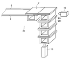
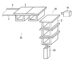
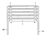
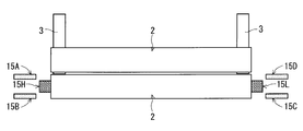
- the horizontally disposed pit cover piece 2 is movable on the rail 3 extending in the horizontal direction. Adjacent horizontally disposed pit cover pieces 2 are in contact with each other in the horizontal direction.
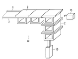
- a recess H ⁇ b> 1 corresponding to the thickness of one pit cover piece 2 is formed between the upper surface of the vertically arranged pit cover piece 2 and the floor surface 30 by the above-described extrusion operation. It is formed.
- FIGS. 3 to 5 The operations described in FIGS. 3 to 5 are repeated until the opening formed in the floor 30 is closed, and the pit cover pieces 2 housed in the pits 20 are successively leveled at the position of the floor 30. Move in the direction.
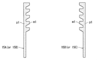
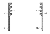
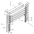
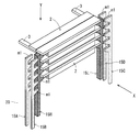
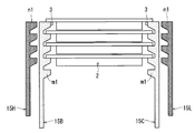
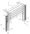
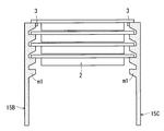
- the vertically disposed pit cover pieces 2 constitute the first holding portions 15A, 15B, 15C, 15D and the second holding portions 15H, constituting the first pit cover moving device. It is held (supported) by 15L.
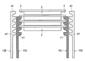
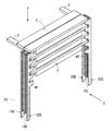
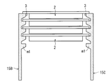
- FIG. 12 and 13 are views showing the state after the extrusion operation.
- FIG. 12 is a perspective view showing a state after the extrusion operation.
- FIG. 13 is a diagram of the configuration diagram of FIG. 12 viewed from the pit 20 (that is, a top view viewed from the Y direction of FIG. 12).
- the first holding portion moving device (not shown) The first holding portions 15A, 15B, 15C, and 15D are moved in a direction to cancel the placement of the vertically disposed pit cover piece 2 by the first placement portion m1.
Landscapes
- Physics & Mathematics (AREA)
- General Physics & Mathematics (AREA)
- Investigating Or Analyzing Materials By The Use Of Ultrasonic Waves (AREA)
- Automatic Analysis And Handling Materials Therefor (AREA)
- Laying Of Electric Cables Or Lines Outside (AREA)
- Vehicle Cleaning, Maintenance, Repair, Refitting, And Outriggers (AREA)
- Underground Structures, Protecting, Testing And Restoring Foundations (AREA)
Abstract
Description
図3は、上記一方の水平配設ピットカバー片2および上記一方の垂直配設ピットカバー片2の具体的な構成を示した。斜視図である。なお、図3では、図面簡略化の観点により、ピットカバー片2とレール3とピットカバー片2の移動させる装置のみを図示、それ以外の構成は省略している。
本実施の形態においても、実施の形態1同様、ピット20の上面部に形成された開口部を塞ぐことが可能な移動式のピットカバーシステムを提供する。本実施の形態においても、ピット20の上面部位置(床面30位置)からピット20内部方向に沿って、垂直方向に配置されることが可能な複数の垂直配設ピットカバー片2を有する。そして、当該垂直配設ピットカバー片2を、当該垂直方向に移動させることが可能な、第一のピットカバー移動装置を有する。また、最上部に位置する垂直配設ピットカバー片2を、開口部を塞ぐように、水平方向に押し出すことが可能な第二のピットカバー移動装置を有する。
2 ピットカバー片、垂直配設ピットカバー片、水平配設ピットカバー片
2A 平板部
2B 箱部
3,4 レール
H1 凹部
10A,10B シャシーダイナモメータ装置
15 第一のピットカバー移動装置
15A,15B,15C,15D 第一の保持部
15H,15L 第二の保持部
16 第二のピットカバー移動装置
20 ピット
30 床面
m1 第一の載置部
n1 第二の載置部
p1,q1 基軸部
Claims (7)
- ピット(20)の上面部に配設された開口部を塞ぐことが可能な移動式のピットカバーシステムであって、
前記ピットの前記上面部位置から前記ピット内部方向に沿って、垂直方向に配置されることが可能な複数のピットカバー片(2)と、
前記垂直方向に配設される前記複数のピットカバー片を、前記垂直方向に移動させることが可能な、第一のピットカバー移動装置(15)と、
前記垂直方向に配置されている前記複数のピットカバー片のうち、最上部に位置する前記ピットカバー片を、前記開口部を塞ぐように、前記垂直方向に対して直角な方向である水平方向に押し出すことが可能な、第二のピットカバー移動装置(16)とを、備えている、
ことを特徴とするピットカバーシステム。 - (A)前記第二のピットカバー移動装置は、前記最上部に位置する前記ピットカバー片を前記水平方向に押し出し、
(B)前記(A)の後に、前記第一のピットカバー移動装置は、前記垂直方向に配設される前記複数のピットカバー片を上方向に移動させる、
ことを特徴とする請求項1に記載のピットカバーシステム。 - 前記ピットカバー片は、
前記ピットの前記上面部位置から前記ピット内部方向に沿って、前記垂直方向に、積み重なって配置されており、
前記第一のピットカバー移動装置は、
前記積み重なっている前記ピットカバー片を、上方向に移動させることができる第一のシリンダー(15)であり、
前記第二のピットカバー移動装置は、
前記積み重なっている前記ピットカバー片のうち、前記最上部に位置する前記ピットカバー片を、前記水平方向に押し出すことができる第二のシリンダー(16)である、
ことを特徴とする請求項2に記載のピットカバーシステム。 - 前記第一のピットカバー移動装置は、
前記垂直方向に所定の間隔だけ隔てて配設されている複数の第一の載置部(m1)を有する櫛状の第一の保持部(15A,15B,15C,15D)と、
前記垂直方向に所定の間隔だけ隔てて配設されている複数の第二の載置部(n1)を有する櫛状であり、前記第一の保持部に隣接して配置される第二の保持部(15H,15L)と、
前記第一の保持部を移動させることが可能な第一の保持部移動装置と、
前記第二の保持部を移動させることが可能な第二の保持部移動装置とを、有しており、
前記垂直方向に配置されている前記複数の前記ピットカバー片において、各前記ピットカバー片は、
前記第一の載置部および前記第二の載置部の少なくとも一方に載置されている、
ことを特徴とする請求項2に記載のピットカバーシステム。 - (a)前記第一の載置部および前記第二の載置部の両方において、前記ピットカバー片が保持されている状態において、前記第一の保持部移動装置は、前記第一の保持部を、前記第一の載置部による前記ピットカバー片の載置を解消する方向に移動させ、
(b)前記(a)の後、前記第二の保持部移動装置は、前記第二の載置部により前記ピットカバー片が保持されている状態で、前記第二の保持部を前記上方向に移動させ、
(c)前記(b)の後、前記第一の保持部移動装置は、前記第一の保持部を、前記第一の載置部により前記ピットカバー片を載置できる方向に移動させる、
ことを特徴とする請求項4に記載のピットカバーシステム。 - (d)前記(c)の後、前記第二の保持部移動装置は、前記第二の保持部を、前記第二の載置部による前記ピットカバー片の載置を解消する方向に移動させ、
(e)前記(d)の後、前記第二の保持部移動装置は、前記第二の保持部を下方向に移動させ、
(f)前記(e)の後、前記第二の保持部移動装置は、前記第二の保持部を、前記第二の載置部により前記ピットカバー片を載置できる方向に移動させる、
ことを特徴とする請求項5に記載のピットカバーシステム。 - 前記第二のピットカバー移動装置は、
垂直方向に配置される前記複数のピットカバー片のうち、前記最上部に位置する前記ピットカバー片を、前記水平方向に押し出すことができるシリンダーであり、
ことを特徴とする請求項4に記載のピットカバーシステム。
Priority Applications (3)
| Application Number | Priority Date | Filing Date | Title |
|---|---|---|---|
| JP2015521206A JP6177906B2 (ja) | 2013-06-05 | 2013-06-05 | ピットカバーシステム |
| CN201380077220.8A CN105264353B (zh) | 2013-06-05 | 2013-06-05 | 井槽盖系统 |
| PCT/JP2013/065530 WO2014196025A1 (ja) | 2013-06-05 | 2013-06-05 | ピットカバーシステム |
Applications Claiming Priority (1)
| Application Number | Priority Date | Filing Date | Title |
|---|---|---|---|
| PCT/JP2013/065530 WO2014196025A1 (ja) | 2013-06-05 | 2013-06-05 | ピットカバーシステム |
Publications (1)
| Publication Number | Publication Date |
|---|---|
| WO2014196025A1 true WO2014196025A1 (ja) | 2014-12-11 |
Family
ID=52007701
Family Applications (1)
| Application Number | Title | Priority Date | Filing Date |
|---|---|---|---|
| PCT/JP2013/065530 Ceased WO2014196025A1 (ja) | 2013-06-05 | 2013-06-05 | ピットカバーシステム |
Country Status (3)
| Country | Link |
|---|---|
| JP (1) | JP6177906B2 (ja) |
| CN (1) | CN105264353B (ja) |
| WO (1) | WO2014196025A1 (ja) |
Citations (3)
| Publication number | Priority date | Publication date | Assignee | Title |
|---|---|---|---|---|
| JP2548143Y2 (ja) * | 1992-08-10 | 1997-09-17 | 三菱重工業株式会社 | 加振装置を収容したピット |
| JP2002116118A (ja) * | 2000-10-10 | 2002-04-19 | Meidensha Corp | ピットカバー装置 |
| JP4244488B2 (ja) * | 2000-03-17 | 2009-03-25 | 株式会社明電舎 | シャシダイナモメータ装置 |
Family Cites Families (2)
| Publication number | Priority date | Publication date | Assignee | Title |
|---|---|---|---|---|
| DE19900620A1 (de) * | 1999-01-11 | 2000-07-13 | Maha Gmbh & Co Kg | Rollenprüfstand für Kraftfahrzeuge |
| US6561013B1 (en) * | 2001-10-30 | 2003-05-13 | Burke E. Porter Machinery Company | Vehicle testing assembly |
-
2013
- 2013-06-05 CN CN201380077220.8A patent/CN105264353B/zh active Active
- 2013-06-05 WO PCT/JP2013/065530 patent/WO2014196025A1/ja not_active Ceased
- 2013-06-05 JP JP2015521206A patent/JP6177906B2/ja active Active
Patent Citations (3)
| Publication number | Priority date | Publication date | Assignee | Title |
|---|---|---|---|---|
| JP2548143Y2 (ja) * | 1992-08-10 | 1997-09-17 | 三菱重工業株式会社 | 加振装置を収容したピット |
| JP4244488B2 (ja) * | 2000-03-17 | 2009-03-25 | 株式会社明電舎 | シャシダイナモメータ装置 |
| JP2002116118A (ja) * | 2000-10-10 | 2002-04-19 | Meidensha Corp | ピットカバー装置 |
Also Published As
| Publication number | Publication date |
|---|---|
| CN105264353A (zh) | 2016-01-20 |
| CN105264353B (zh) | 2018-09-14 |
| JP6177906B2 (ja) | 2017-08-09 |
| JPWO2014196025A1 (ja) | 2017-02-23 |
Similar Documents
| Publication | Publication Date | Title |
|---|---|---|
| JP5374409B2 (ja) | 鉄道車両のバッテリー格納装置 | |
| CN105986718B (zh) | 具有与门尺寸无关的门配件的推拉门 | |
| JP2018518648A (ja) | 密閉箱 | |
| KR101845735B1 (ko) | 3 차원 인쇄 장치 | |
| JP2013050477A5 (ja) | ||
| JP6301535B2 (ja) | ピットカバーシステム | |
| JP6177906B2 (ja) | ピットカバーシステム | |
| CN105824200B (zh) | 一种基板支撑结构及曝光机 | |
| CN112478560B (zh) | 一种仓储装置及入库、出库控制方法 | |
| JP2010110800A (ja) | ダイカスト鋳造型およびダイカスト鋳造方法 | |
| JP5184495B2 (ja) | 床用目地装置 | |
| JP2018016962A (ja) | 床用目地装置 | |
| JP6239462B2 (ja) | 試験装置 | |
| CN104959566A (zh) | 汽油马达盖的加工模具 | |
| CN108143095B (zh) | 升降工作桌 | |
| JP6572000B2 (ja) | 電気機器収納用ラック | |
| JP3132984U (ja) | レベリングブロック | |
| JP5203156B2 (ja) | 床用目地装置 | |
| JP2015068031A (ja) | 床用目地装置 | |
| JP2012051003A (ja) | カウンタカム装置 | |
| CN108266936B (zh) | 冰箱 | |
| JP2017074742A (ja) | 三次元造形装置 | |
| CN205541935U (zh) | 磁头静态机械参数测试工装 | |
| CN108216829B (zh) | 抽屉式料盘储料柜 | |
| CN202535119U (zh) | 可并联的手动电池充电交换机构 |
Legal Events
| Date | Code | Title | Description |
|---|---|---|---|
| WWE | Wipo information: entry into national phase |
Ref document number: 201380077220.8 Country of ref document: CN |
|
| 121 | Ep: the epo has been informed by wipo that ep was designated in this application |
Ref document number: 13886392 Country of ref document: EP Kind code of ref document: A1 |
|
| ENP | Entry into the national phase |
Ref document number: 2015521206 Country of ref document: JP Kind code of ref document: A |
|
| NENP | Non-entry into the national phase |
Ref country code: DE |
|
| 122 | Ep: pct application non-entry in european phase |
Ref document number: 13886392 Country of ref document: EP Kind code of ref document: A1 |