WO2014192926A1 - 点滴スタンド、及び、点滴スタンド用のアタッチメント - Google Patents
点滴スタンド、及び、点滴スタンド用のアタッチメント Download PDFInfo
- Publication number
- WO2014192926A1 WO2014192926A1 PCT/JP2014/064447 JP2014064447W WO2014192926A1 WO 2014192926 A1 WO2014192926 A1 WO 2014192926A1 JP 2014064447 W JP2014064447 W JP 2014064447W WO 2014192926 A1 WO2014192926 A1 WO 2014192926A1
- Authority
- WO
- WIPO (PCT)
- Prior art keywords
- tray
- handle
- infusion
- support column
- attachment
- Prior art date
Links
Images


Classifications
-
- A—HUMAN NECESSITIES
- A61—MEDICAL OR VETERINARY SCIENCE; HYGIENE
- A61M—DEVICES FOR INTRODUCING MEDIA INTO, OR ONTO, THE BODY; DEVICES FOR TRANSDUCING BODY MEDIA OR FOR TAKING MEDIA FROM THE BODY; DEVICES FOR PRODUCING OR ENDING SLEEP OR STUPOR
- A61M5/00—Devices for bringing media into the body in a subcutaneous, intra-vascular or intramuscular way; Accessories therefor, e.g. filling or cleaning devices, arm-rests
- A61M5/14—Infusion devices, e.g. infusing by gravity; Blood infusion; Accessories therefor
- A61M5/1414—Hanging-up devices
- A61M5/1415—Stands, brackets or the like for supporting infusion accessories
-
- A—HUMAN NECESSITIES
- A47—FURNITURE; DOMESTIC ARTICLES OR APPLIANCES; COFFEE MILLS; SPICE MILLS; SUCTION CLEANERS IN GENERAL
- A47B—TABLES; DESKS; OFFICE FURNITURE; CABINETS; DRAWERS; GENERAL DETAILS OF FURNITURE
- A47B13/00—Details of tables or desks
- A47B13/003—Connecting table tops to underframes
-
- A—HUMAN NECESSITIES
- A61—MEDICAL OR VETERINARY SCIENCE; HYGIENE
- A61M—DEVICES FOR INTRODUCING MEDIA INTO, OR ONTO, THE BODY; DEVICES FOR TRANSDUCING BODY MEDIA OR FOR TAKING MEDIA FROM THE BODY; DEVICES FOR PRODUCING OR ENDING SLEEP OR STUPOR
- A61M5/00—Devices for bringing media into the body in a subcutaneous, intra-vascular or intramuscular way; Accessories therefor, e.g. filling or cleaning devices, arm-rests
- A61M5/14—Infusion devices, e.g. infusing by gravity; Blood infusion; Accessories therefor
- A61M5/1414—Hanging-up devices
- A61M5/1417—Holders or handles for hanging up infusion containers
-
- A—HUMAN NECESSITIES
- A61—MEDICAL OR VETERINARY SCIENCE; HYGIENE
- A61G—TRANSPORT, PERSONAL CONVEYANCES, OR ACCOMMODATION SPECIALLY ADAPTED FOR PATIENTS OR DISABLED PERSONS; OPERATING TABLES OR CHAIRS; CHAIRS FOR DENTISTRY; FUNERAL DEVICES
- A61G7/00—Beds specially adapted for nursing; Devices for lifting patients or disabled persons
- A61G7/05—Parts, details or accessories of beds
- A61G7/0503—Holders, support devices for receptacles, e.g. for drainage or urine bags
Definitions
- the present invention relates to an infusion stand used when instilling a patient in a hospital, a nursing facility, a home, or the like, and an attachment for an infusion stand.
- This application claims priority based on Japanese Patent Application No. 2013-111602 filed in Japan on May 31, 2013 and Japanese Patent Application No. 2013-116003 filed in Japan on May 31, 2013, The contents are incorporated here.
- Infusion is a mechanism in which an infusion pack is placed at a higher position than the patient, and the infusion in the infusion pack is sent into the patient's body using gravity. Therefore, it is common to use an infusion stand that supports the infusion pack above the patient.
- a support column that extends in the vertical direction is attached to a leg that is placed on the floor surface, and an infusion suspension is attached to the upper end of the support column.
- an infusion suspension is attached to the upper end of the support column.
- the infusion suspension is provided with a pair of arm portions extending in a substantially horizontal direction from the upper end of the support column, and the distal end portion of each arm portion. And a hook portion for hanging.
- Each of these drip stands is provided with casters on the legs so that a patient, a nurse or the like can freely move the stand as needed.
- a tray (article mounting table) is provided on the drip stand as a surface for placing the patient's belongings when moving and a work surface for hanging the infusion pack. desirable. In such a configuration, the convenience of the drip stand can be further improved.
- the drip stand described in Patent Document 2 is provided with a grip handle that includes an annular handle body, a boss portion fixed to the outer surface of the support column, and a connecting portion that connects the boss portion and the handle body. ing.
- the stand can be moved by gripping the grip handle from any direction around the support column.
- the stand can be operated by holding the grip handle by a plurality of persons. For this reason, the operability as an infusion stand is good.
- the tray and the grip handle as described above on the support portion of the drip stand.
- a plurality of projecting parts from the support part can be formed in the separated parts of the support part, and the appearance may be lowered.
- a restriction portion on the tray.
- a tray having a restriction portion is employed, not only the appearance is lowered as described above, but also the space occupied by the tray on the column portion is increased.
- an object of the present invention is to provide an infusion stand that can improve convenience and operability without deteriorating appearance or increasing occupied space.
- Another object of the present invention is to provide an infusion stand that can improve convenience and operability without deteriorating the appearance or complicating the installation work, and an attachment for the infusion stand.
- a first aspect of the present invention is an infusion stand in which an infusion pack is suspended and supported via an infusion hanging tool on a support column extending in the vertical direction, and has an article placement surface on which an article can be placed.
- a tray and a guide member that is disposed above at least a part of the article placement surface of the tray and regulates the fall of the article placed on the tray, and the tray and the guide member are directly Alternatively, a grip space portion that is indirectly connected to the support column and that allows an operator to grip the guide member as a grip handle is provided between the guide member and the tray.
- an operator such as a patient or a nurse can operate the drip stand by gripping the guide member above the tray as a grip handle.
- the tray and the guide member are not arranged far apart in the vertical direction of the support column.
- the second aspect of the present invention is the drip stand according to the first aspect, wherein the tray is provided with an insertion hole through which the support column is inserted in the vertical direction.
- the tray is provided with an insertion hole through which the support column is inserted in the vertical direction.
- the insertion hole is provided at a position offset from the center of the tray in a top view. In this case, it is possible to secure a collective article placement space on the tray that does not interfere with the support column.
- the guide member is disposed at an upper position along the outer peripheral edge of the tray. In this case, almost the entire upper surface of the tray can be used as the article placement surface.
- the inner peripheral surface of the guide member is outside the outer peripheral surface of the tray or substantially at the same position in a top view. Formed.
- the guide member since the guide member is not located on the inner side of the tray in plan view, almost the entire upper surface of the tray can be effectively used as the article placement surface. Further, when the operator grips the guide member as a grip handle, the tray is less likely to get in the way.
- the guide member is formed to have a shape similar to the outer edge shape of the tray in a top view. In this case, the appearance balance becomes good and the appearance from the outside does not deteriorate.
- the guide member is formed to have an annular shape when viewed from above. In this case, when the operator grips the guide member as a grip handle, the guide member can be gripped from any direction.
- An eighth aspect of the present invention is an infusion stand in which an infusion pack is supported by suspension through an infusion suspension tool on a support column extending in the vertical direction, and has an article placement surface on which an article can be placed.
- a tray a grip handle that is spaced apart so as to ensure a grip space that an operator can grip between the tray, a connecting portion that connects the tray and the grip handle, the tray, and the tray And an attachment that attaches at least one of the grip handles to the support post.
- the tray and the grip handle can be attached to the support column via the mounting portion as an integral attachment.
- the attachment portion is provided in the connection portion.
- the entire attachment can be made more compact, and the appearance is improved.
- the tray is provided with an insertion hole through which the column portion is inserted in the vertical direction.
- the column portion is not disposed outside the tray, the amount of the tray protruding from the column portion can be suppressed small.
- the grip handle is formed to have a shape similar to the outer edge shape of the tray in a top view. In this case, the appearance balance becomes good and the appearance from the outside does not deteriorate.
- the grip handle is formed in an annular shape when viewed from above. In this case, when the operator grips the grip handle, the grip handle can be gripped from any direction.
- a thirteenth aspect of the present invention is an attachment for an infusion stand attached to a support column extending in the vertical direction of an infusion stand, the tray having an article placement surface on which an article can be placed, and the tray.
- the guide member on the upper side of the tray by a predetermined distance can function as both a restricting portion for restricting dropping of the article and a grip handle. Therefore, an article can be easily placed on the tray without causing a decrease in appearance and an increase in occupied space due to the tray and the grip handle being spaced apart on the support shaft, and the operator can guide the guide member.
- the drip stand can be easily operated by gripping.
- the tray and the grip handle can be compactly attached to the support column as an integral attachment. Therefore, an article can be easily placed on the tray without causing deterioration in appearance and complication of attachment work, and the operator can easily operate the drip stand by holding the grip handle.
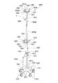
- FIGS. 1 to 6 are perspective views showing the appearance of an infusion stand 1 according to this embodiment.
- the infusion stand 1 includes a leg block 2 placed on the floor of a hospital, a care facility, a home, etc., a support column 3 supported by the leg block 2 and extending in the vertical direction, and a support unit. 3 and an infusion hanging tool 4 that supports the infusion pack P in a suspended manner.
- the leg block 2 includes five leg frames 11 that extend radially to the outer peripheral side of the boss 10 that holds the lower end of the support column 3, and casters 12 that are attached to the extending ends of the leg frames 11. Therefore, the leg block 2 of this embodiment is movable on the floor surface via the casters 12. In the case of this embodiment, the upper side of the boss portion 10 and the leg frame 11 is actually covered with the resin cover member 13. However, in FIGS. Reference numerals 10 and 11 are attached to portions corresponding to the boss portion 10 and the leg frame 11.
- the support column 3 includes a hollow outer support column 3A whose lower end is attached to the leg block 2 and a hollow inner support column 3B to which the infusion suspension 4 is attached to the upper end.
- the lower region of the support column 3B is slidably fitted into the upper portion of the outer support column 3A.
- a lock mechanism (not shown) for fixing the relative position of the outer support column 3A and the inner support column 3B is provided inside the support column 3. By releasing the lock mechanism, the relative position of the outer column 3A and the inner column 3B (the length of expansion / contraction of the column 3) can be adjusted as appropriate.
- a release operation sleeve 14 for releasing the lock mechanism is installed at a substantially middle portion of the inner column 3B in the vertical direction.
- the release operation sleeve 14 is connected to the lock release piece of the lock mechanism inside the inner column 3B.
- the lock mechanism is released when the operator slides upward by an operator such as a nurse, and the lock mechanism is maintained in the locked state again when operated downward.
- a loading hook attachment 15 and a handle attachment 16 are attached to the outer support column 3A so as to be adjustable up and down.
- the loading hook attachment 15 includes a boss portion 17 that can be fastened and fixed to the outer peripheral surface of the outer support column 3A, and a pair of hook portions 18 and 18 that extend in the opposite direction from the boss portion 17. 18 can support a hanging bag, baggage 19 and the like as appropriate.
- the handle attachment 16 will be described in detail later.
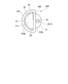
- the infusion suspension 4 is a substantially rectangular shape standing up and down so as to surround the boss portion 27 fastened and fixed to the upper end of the inner support 3B of the support 3 and the axis o of the support 3.
- a cylindrical peripheral wall 28, a connecting column 29 that connects the boss 27 and the peripheral wall 28, and an outer surface of the lower end of the peripheral wall 28 project outward (on the opposite side to the side where the axis o of the column 3 is located).
- four suspension support pieces 30 are provided.
- the peripheral wall 28 is formed in such a manner that four support walls 31..., Which are rounded in the shape of an arc on both sides in the left-right direction, are arranged in a square shape and adjacent support walls 31, 31 are connected to each other.
- the entire peripheral wall 28 is integrally formed in a rectangular tube shape by a hard resin material.
- the outer surface 31a of each support wall 31 (the surface on the side opposite to the side where the axis center o of the support column 3 is located) is formed substantially flat with a central region in the width direction as a center.
- connection struts 29 are provided in a total of four so as to connect the center position in the width direction of the lower edge of each support wall 31 and the outer surface of the boss portion 27.
- the suspension support piece 30 is formed in a substantially L-shaped cross section by a metal plate material. One side of the L shape is attached to the center position in the width direction of the lower edge of the corresponding support wall 31, and the other side of the L shape extends upward. The tip of one side of the L-shape of the suspension support piece 30 is inserted into the corresponding support wall 31 and the connection column 29 and fixed to the connection column 29. As shown in FIG. 1, the suspension hole 30 of the infusion pack P can be engaged with each suspension support piece 30.
- symbol 8a in FIG. 1 is the upper seal part of the infusion pack P in which the suspending hole 7 is formed
- symbol 9 is the extraction pipe
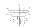
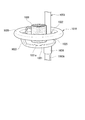
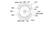
- FIGS. 3 and 4 are perspective views showing the handle attachment 16 portion
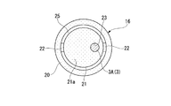
- FIG. 5 is a top view of the handle attachment 16 portion showing the support post 3 in a broken view
- FIG. 6 is a side view of a portion of the handle attachment 16 partly in section.
- the handle attachment 16 has a tray 21 on which an everyday item such as a cup and other articles 26 can be placed on the upper surface, and a handle main body 20 (an annular grip handle disposed at a predetermined distance above the tray 21.
- a guide member a pair of connecting struts 22 and 22 (connecting portions) for connecting the tray 21 and the handle main body 20, and a boss portion 24 (mounting portion) that can be fastened and fixed to the outer peripheral surface of the outer strut 3A. I have.
- the tray 21 is formed in a circular flat plate shape that is slightly smaller than the inner peripheral surface of the handle body 20, and its upper surface is an article placement surface 21 a for placing the article 26.
- the tray 21 is disposed on the lower side of the handle main body 20 coaxially with the handle main body 20, and is connected to the handle main body 20 by connecting columns 22 and 22 at opposing positions on the outer periphery of the tray 21.
- the connection column 22 is disposed so as to be inclined so as to connect the upper surface on the outer peripheral side of the tray 21 and the lower surface on the inner peripheral side of the handle body 20.
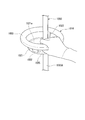
- the tray 21 is provided with an insertion hole 23 penetrating vertically at a position offset from the center portion thereof, and the outer support column 3A is inserted through the insertion hole 23.
- the tray 21, the connecting struts 22 and 22, and the handle body 20 are integrally formed with a hard resin together with a part of the boss portion 24.
- the boss portion 24 is provided at a position that is coaxial with the insertion hole 23 on the lower surface of the tray 21.
- the boss portion 24 includes a half-cylindrical inner cylinder 24a provided so as to protrude from the lower surface of the tray 21, and an outer cylinder 24b attached to the outside of the inner cylinder 24a.
- the inner cylinder 24a can be deformed radially inward with the halved portion as the center, and a male screw 50 is provided on the outer peripheral surface.
- the outer cylinder 24b is provided with a female screw 51 that can be screwed with the male screw 50 of the inner cylinder 24a.
- the outer cylinder 24a By tightening the male cylinder 50 on the male screw 50 of the inner cylinder 24a, the outer cylinder 24a has an outer peripheral surface of the column portion 3 (outer column 3A). Can be fixed by pressure. Accordingly, by loosening the tightening of the outer cylinder 24b of the boss portion 24, the handle attachment 16 can move on the column portion 3 (outer column 3A), and the handlebar 16 can be re-tightened at a desired position by retightening the outer tube 24b.
- the attachment 16 can be fixed with respect to the support
- the tray 21 is directly connected to the support column 3 via the boss portion 24, and the handle body 20 (guide member) is indirectly connected to the support column 3 via the tray 21. .
- a sufficient holding space 25 is secured for the operator to hold the handle body 20. Therefore, an operator such as a patient or a nurse can grip the handle body 20 and move the drip stand 1 in a free direction unless the caster 12 of the leg block 2 is locked.
- the handle body 20 also functions as a guide member (regulator) that regulates the fall of the article 26 placed on the tray 21.
- the tray 21 may interfere with the outer column 3A.
- the upper surface of the handle body 20 is formed so that the entire region is substantially horizontal, so that a large article such as an infusion pack P is placed on the upper surface of the handle body 20 as necessary. It is also possible.
- the handle attachment 16 attached to the support column 3 has the flat tray 21 having the article placement surface 21a, and the tray 21 above the article placement surface 21a.
- a handle body 20 that is an annular guide member disposed so as to surround the handle body 20, and a grip space 25 is secured between the handle body 20 and the tray 21. Therefore, the placement function unit and the grip handle function unit of the article 26 can be compactly integrated and installed around the support column 3. For this reason, in the drip stand 1 of this embodiment, the operator can place the article 26 around the support column 3 and move it without moving the appearance of the support column 3 and increasing the occupied space. It is possible to realize both of the reliable gripping by.
- the handle body 20 also functions as a guide member (regulator) that regulates the fall of the article 26 placed on the article placement surface 21 a of the tray 21. Convenience when the article 26 is placed thereon can be further enhanced. Therefore, in the case of this drip stand 1, while the handle attachment 16 has a function of restricting the drop of the article 26, an increase in occupied space can be suppressed and the overall appearance can be reduced.
- the tray 21 of the handle attachment 16 can be arranged outside the support column 3 by a connecting arm or the like extending from the side of the tray 21, but in the drip stand 1 of this embodiment, the handle attachment 16 Since the insertion hole 23 is provided in the tray 21 and the column portion 3 is inserted into the insertion hole 23, the amount of the tray 21 protruding from the column portion 3 can be further reduced. Therefore, in this infusion stand 1, the convenience and appearance as an infusion stand can be further enhanced.
- the insertion hole 23 is provided at a position that is offset from the center position of the tray 21 in a top view, the collective article placement that does not interfere with the support column 3 on the tray 21. Space can be secured. For this reason, in the drip stand 1, it is possible to suppress the amount of protrusion of the tray 21 while ensuring the ease of placing the article 26 on the tray 21.
- the handle attachment 16 does not necessarily have to be provided with the insertion hole 23 at a position offset from the center position of the tray 21, and the insertion hole 23 is not positioned at the center position of the tray 21 as in the modification shown in FIG. 7. It is also possible to provide it.
- the handle body 20 of the handle attachment 16 is disposed above at least a part of the article placement surface 21 a of the tray 21, the handle body 20 is necessarily disposed at an upper position of the tray 21 along the outer peripheral edge of the tray 21. It does not have to be. However, since the drip stand 1 of this embodiment is disposed at an upper position of the tray 21 so that the handle body 20 is along the outer peripheral edge of the tray 21, a wide region on the upper surface of the tray 21 is placed on the article. It can be used effectively as the surface 21a. In particular, in the case of this embodiment, the handle main body 20 of the handle attachment 16 is arranged so that the inner peripheral surface of the handle main body 20 is outside the outer peripheral surface of the tray 21 in a top view.
- the handle body 20 may be formed so that the inner peripheral surface of the handle main body 20 is substantially at the same position as the outer peripheral surface of the tray 21 when viewed from above.
- the handle main body 20 of the handle attachment 16 disposed above the tray 21 is formed in a shape similar to the outer edge shape of the tray 21, so that the appearance balance is good. The appearance from the outside does not deteriorate.
- the handle main body 20 of the handle attachment 16 does not necessarily need to be annular as long as it is disposed above at least a part of the article placement surface 21a of the tray 21.
- the drip stand 1 of this embodiment has the handle body 20 formed in an annular shape, when the operator holds the handle body 20 as a holding handle, it can be held from any direction in the peripheral area, and the operability is improved. Has the advantage of being good.
- FIGS. 8A to 11 are a perspective view and a top view of the handle attachment 116 portion of the second embodiment.
- the handle attachment 116 according to this embodiment includes a disc-shaped tray 21 whose upper surface is an article placement surface 21a, and an annular handle body 20 (guide member) that is disposed at a predetermined distance above the tray 21. And).
- the handle body 20 is disposed so as to be concentric with the tray 21, and a gripping space portion 25 is secured between the handle body 20 and the tray 21.
- the inner peripheral surface of the handle body 20 is formed in a circular shape that is slightly larger than the outer peripheral surface of the tray 21.
- the handle main body 20 and the tray 21 are connected by a pair of connecting columns disposed at opposite positions on the circumference.
- the handle main body 20 and the tray 21 are connected together.
- the two connecting columns 122 are connected.
- the connecting strut 122 is integrally formed with a trapezoidal bulging portion 33 that bulges radially inward from the inner peripheral surface of the handle body 20 to a position reaching the outer peripheral edge of the tray 21.
- An insertion hole 23 through which the outer column 3 ⁇ / b> A of the column 3 is inserted in the vertical direction is formed in the bulge 33 and a portion connected to the bulge 33 on the tray 21.
- the bulging portion 33 constitutes at least a part of an attachment portion for attaching the handle attachment 116 to the support column portion 3. In the case of this embodiment, the insertion hole 23 is disposed at a position offset from the center position of the tray 21.
- pillar part 3 may be provided in the bulging part 33, you may provide in the lower surface side of the tray 21 similarly to 1st Embodiment.
- the infusion stand of this embodiment can obtain the same basic effects as those of the first embodiment. Further, since the handle main body 20 of the handle attachment 116 is connected to the connection support column 122 only at one place in the circumferential direction, when the operator grips the handle main body 20 as a grip handle, it does not interfere with the connection support column 122. It is possible to enhance the operability by expanding the area that can be gripped. Further, the appearance quality can be further improved.
- the connecting column 122 that connects the handle body 20 and the tray 21 is provided with the bulging portion 33 that constitutes at least a part of the mounting portion that attaches the handle attachment 116 to the column portion 3.
- the handle attachment 116 itself can be made more compact.
- the tray 21 and the handle body 20 are connected obliquely by the connecting column 122 without providing the bulging portion on the connecting column 122.
- FIG. 9A is a top view of the handle attachment 216 portion of the third embodiment.
- the handle attachment 216 of this embodiment includes a disc-shaped tray 21 whose upper surface is an article placement surface 21a, a handle body 220 (guide member) that is spaced above the tray 21 by a predetermined distance, The gripping space 25 is secured between the handle body 220 and the tray 21.
- the handle main body 220 is not a complete annular shape, but is an arc shape in which a part of a circle is cut out.
- the handle body 220 is disposed so as to be concentric with the tray 21.
- the arc ends on both sides of the handle main body 220 and the central area of the arc are connected to the outer peripheral edge of the tray 21 by three connecting columns 22.
- An insertion hole 23 through which the column 3 is inserted is provided at a position offset from the center position of the tray 21.
- the inner surface of the handle body 220 is formed in a circular shape that is slightly larger than the outer peripheral surface of the tray 21.
- a concave space 35 that is recessed in a substantially fan shape toward the outer peripheral surface of the tray 21 when viewed from above is provided between the arc ends on both sides of the handle body 220.
- the drip stand of this embodiment can obtain the same basic effects as those of the first embodiment.
- the handle main body 220 of the handle attachment 216 is formed in a circular arc shape in which a part of the circular shape is cut out, and a concave space 35 is provided between the circular arc ends on both sides thereof. Therefore, for example, when an infusion pump is connected to an infusion pack suspended from an infusion suspension and an infusion tube is connected to the patient via the infusion pump, the tubes drawn from the infusion pack are handled by the handle. It can be pulled out through the concave space 35 without interfering with the main body 220. For this reason, the workability
- the example in which the insertion hole 23 is disposed at a position offset from the center position of the tray 21 has been described, but the insertion hole 23 may be disposed at the center position of the tray 21 as in the modification shown in FIG. 9B. good.
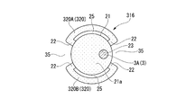
- FIG. 10A is a top view of the handle attachment 316 portion of the fourth embodiment.
- the handle attachment 316 of this embodiment includes a disc-shaped tray 21 whose upper surface is an article placement surface 21a, a handle main body 320 (guide member) disposed at a predetermined distance above the tray 21, and The gripping space 25 is secured between the handle body 320 and the tray 21.
- the handle main body 320 includes a pair of arc-shaped handle pieces 320A and 320B. Both end portions of the handle pieces 320 ⁇ / b> A and 320 ⁇ / b> B are coupled to the outer peripheral edge portion of the tray 21 by the coupling column 22.
- a concave space 35 is provided between each of the adjacent handle pieces 320A and 320B.
- an insertion hole 23 through which the column portion 3 is inserted in the vertical direction is provided at a position offset toward the one concave space 35 with respect to the center position of the tray 21.
- the drip stand of this embodiment can basically obtain the same effects as those of the third embodiment. Furthermore, since two concave spaces 35 are provided at opposite positions on the circumference of the handle main body 320, it is possible to draw the tubes downward from a plurality of locations around the tray 21 during the drip operation. Therefore, workability and convenience at the time of infusion can be further enhanced.
- the insertion hole 23 may be arranged at the center position of the tray 21 as in the modification shown in FIG. 10B.
- FIG. 11 is a top view of the handle attachment 416 portion of the fifth embodiment.
- the handle attachment 416 of this embodiment includes a disc-shaped tray 21 whose upper surface is an article placement surface 21a, a handle main body 420 (guide member) disposed at a predetermined distance above the tray 21, and The gripping space 25 is secured between the handle body 420 and the tray 21.
- the handle body 420 is formed in a substantially D shape having a semicircular arc portion 420a and a straight portion 420b that linearly connects both ends of the arc portion 420a.
- the handle main body 420 is disposed at a position offset outward from the column portion 3 on the upper side of the tray 21.
- the arcuate portion 420a of the handle body 420 is formed to have an outer diameter that is slightly larger than the outer diameter of the tray 21, and is connected to the outer peripheral edge portion of the tray 21 by the three connecting columns 22 so as to be concentric with the center of the tray 21. ing.
- the straight portion 420 b of the handle main body 420 is disposed so as to cross over the tray 21 at a position offset to the outside of the support column portion 3.
- a substantially semicircular space 435 is provided outside the straight portion 420 b of the handle body 420.
- the drip stand of this embodiment can basically obtain substantially the same effect as the third and fourth embodiments.
- the handle body 420 is formed in a substantially D shape
- the support column 3 is disposed outside the handle body 420
- a substantially semicircular space 435 is provided outside the handle body 420. Therefore, a larger space for pulling out the tubes downward can be secured at a position adjacent to the outside of the handle main body 420, and the articles placed on the article placement surface 21 a of the tray 21 can be Interference can be prevented.
- FIGS. 12 to 17 are perspective views showing the appearance of an infusion stand 1001 according to this embodiment.
- the drip stand 1001 includes a leg block 1002 placed on the floor of a hospital, a nursing facility, a home, etc., a support column 1003 supported by the leg block 1002 and extending in the vertical direction, and a support column An infusion suspension tool 1004 that is attached to the upper end of 1003 and supports the infusion pack P in a suspended manner.
- the leg block 1002 includes five leg frames 1011 that extend radially to the outer peripheral side of the boss 1010 that holds the lower end of the support column 1003, and casters 1012 that are attached to the extending ends of the leg frames 1011. Therefore, the leg block 1002 of this embodiment is movable on the floor surface via the casters 1012. In the case of this embodiment, the upper side of the boss portion 1010 and the leg frame 1011 is actually covered with a resin cover member 1013. However, in FIGS. Reference numerals 1010 and 1011 are assigned to portions corresponding to the boss portion 1010 and the leg frame 1011.
- the support column 1003 includes a hollow outer support column 1003A whose lower end is attached to the leg block 1002, and a hollow inner support column 1003B to which an infusion suspension 1004B is attached to the upper end.
- the lower region of the support column 1003B is slidably fitted into the upper portion of the outer support column 1003A.
- a lock mechanism (not shown) for fixing the relative position of the outer support column 1003A and the inner support column 1003B is provided inside the support column 1003, a lock mechanism (not shown) for fixing the relative position of the outer support column 1003A and the inner support column 1003B is provided inside the support column 1003, a lock mechanism (not shown) for fixing the relative position of the outer support column 1003A and the inner support column 1003B is provided inside the support column 1003, a lock mechanism (not shown) for fixing the relative position of the outer support column 1003A and the inner support column 1003B is provided inside the support column 1003, a lock mechanism (not shown) for fixing the relative position of the outer support column 1003
- a release operation sleeve 1014 for releasing the lock mechanism is provided at a substantially middle portion in the vertical direction of the inner support column 1003B.
- the release operation sleeve 1014 is connected to the lock release piece of the lock mechanism inside the inner column 1003B.
- the lock mechanism is released when the operator slides upward by an operator such as a nurse, and the lock mechanism is maintained in the locked state again when operated downward.
- a loading hook attachment 1015 and a handle attachment 1016 that is an attachment for an infusion stand according to this embodiment are attached to the outer support column 1003A so as to be adjustable up and down.
- the loading hook attachment 1015 includes a boss portion 1017 that can be fastened and fixed to the outer peripheral surface of the outer support column 1003A, and a pair of hook portions 1018 and 1018 extending in the opposite direction from the boss portion 1017.
- a bag, baggage 1019, and the like can be appropriately suspended and supported at 1018.
- the handle attachment 1016 will be described in detail later.
- the infusion suspension 1004 has a boss portion 1027 fastened and fixed to the upper end portion of the inner support column 1003B of the support column portion 1003, and a substantially rectangular shape erected along the vertical direction so as to surround the axis center o of the support column portion 1003.
- a cylindrical peripheral wall 1028, a connecting column 1029 that connects the boss portion 1027 and the peripheral wall 1028, and an outer surface of the lower end portion of the peripheral wall 1028 project outward (on the opposite side to the side where the axis center o of the column portion 1003 is located).
- four suspension support pieces 1030 are provided.
- the peripheral wall 1028 is formed in such a manner that four support walls 1031... Are rounded in a circular arc shape on both sides in the left-right direction, and adjacent support walls 1031 and 1031 are connected to each other.
- the entire peripheral wall 1028 is integrally formed of a hard resin material in a rectangular tube shape.
- the outer surface 1031a of each support wall 1031 (the surface opposite to the side where the axis center o of the support column 1003 is located) is formed substantially flat with the center region in the width direction as the center.
- the suspension support piece 1030 is formed in a substantially L-shaped cross section by a metal plate material. One side of the L shape is attached to the center position in the width direction of the lower edge of the corresponding support wall 1031, and the other side of the L shape extends upward. The tip of one side of the L-shape of the suspension support piece 1030 is inserted into the corresponding support wall 1031 and the connection column 1029 and fixed to the connection column 1029. As shown in FIG. 12, a suspension hole 1007 of the infusion pack P can be engaged with each suspension support piece 1030.
- symbol 1008a in FIG. 12 is the upper seal part of the infusion pack P in which the hanging hole 1007 is formed, and the code
- symbol 1009 is the extraction
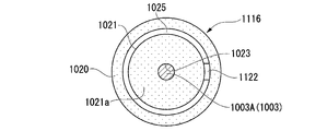
- FIG. 14 and 15 are perspective views showing the handle attachment 1016 portion
- FIG. 16 is a top view of the handle attachment 1016 portion with the strut portion 1003 broken away.
- FIG. 17 is a side view of a handle attachment 1016 portion with a part thereof in cross section.
- the handle attachment 1016 includes a tray 1021 on which an everyday item such as a cup and other articles 1026 can be placed on an upper surface, and an annular grip handle 1020 (guide member) disposed at a predetermined distance above the tray 1021. And a pair of connecting struts 1022 and 1022 (connecting portions) for connecting the tray 1021 and the grip handle 1020 and a boss portion 1024 (attaching portion) that can be fastened and fixed to the outer peripheral surface of the outer strut 1003A. Yes.
- the tray 1021 is formed in a circular flat plate shape that is slightly smaller than the inner peripheral surface of the grip handle 1020, and its upper surface is an article placement surface 1021 a on which the article 1026 is placed.
- the tray 1021 is disposed on the lower side of the grip handle 1020 and coaxially with the handle main body 20, and is connected to the grip handle 1020 by connecting struts 1022 and 1022 at opposing positions on the outer periphery of the tray 1021.
- the connecting column 1022 is disposed so as to be inclined so as to connect the upper surface on the outer peripheral side of the tray 1021 and the lower surface on the inner peripheral side of the grip handle 1020.
- the tray 1021 is provided with an insertion hole 1023 penetrating vertically at a position offset from the center thereof, and the outer column 1003A of the column part 1003 is inserted into the insertion hole 1023.
- the tray 1021, the connecting columns 1022 and 1022, and the grip handle 1020 are integrally formed with a hard resin together with a part of the boss portion 1024.
- the boss portion 1024 is provided at a position coaxial with the insertion hole 1023 on the lower surface of the tray 1021.
- the boss portion 1024 includes a half-cylindrical inner cylinder 1024a provided so as to protrude from the lower surface of the tray 1021, and an outer cylinder 1024b attached to the outside of the inner cylinder 1024a.
- the inner cylinder 1024a can be deformed radially inward with the half portion as a center, and a male screw 1050 is provided on the outer peripheral surface.
- the outer cylinder 1024b is provided with a female screw 1051 that can be screwed with the male screw 1050 of the inner cylinder 1024a. It can be fixed by pressure.
- the handle attachment 1016 can move on the support column 1003 (outer support column 1003A), and the handle is secured by retightening the outer tube 1024b at a desired position.
- the attachment 1016 can be fixed to the support column 1003 (outer support column 1003A).
- a grip space 1025 sufficient for the operator to grip the grip handle 1020 is secured below the grip handle 1020 connected to the tray 1021 by the pair of connection posts 1022 and 1022. Therefore, an operator such as a patient or a nurse can grip the grip handle 1020 and move the drip stand 1001 in a free direction unless the caster 1012 of the leg block 1002 is locked.
- the grip handle 1020 also functions as a guide member (regulator) that regulates the fall of the article 1026 placed on the tray 1021.
- the tray 1021 since the insertion hole 1023 on the tray 1021 through which the outer column 1003A is inserted is disposed at a position offset from the center of the tray 1021, the tray 1021 may interfere with the outer column 1003A. There is no sufficient article placement space.
- the upper surface of the grip handle 1020 is formed so that the entire region is substantially horizontal, a large article such as an infusion pack P is placed on the upper surface of the grip handle 1020 as necessary. It is also possible.
- the grip 102 is secured by arranging the tray 1021 and the grip handle 1020 apart from each other, so that the outer shape of the handle attachment 1016 as a whole is secured. Can be kept compact.
- the drip stand 1001 according to this embodiment is configured such that the tray 1021 and the grip handle 1020 of the handle attachment 1016 are mutually connected by the connecting column 1022 so that a grip space portion 1025 is secured between the grip handle 1020 and the tray 1021.
- a boss portion 1024 as an attachment portion is integrally provided on the lower surface side of the tray 1021. Therefore, the placement function unit and the grip handle function unit of the article 1026 can be integrated together compactly and easily attached around the support column 1003.
- the article 1026 is placed around the support column 1003 and the operation is performed without moving the display unit 1003 without deteriorating the appearance around the support column 1003 and the workability of the attachment. Both reliable gripping by a person can be realized.
- the grip handle 1020 of the handle attachment 1016 also functions as a guide member (regulator) that regulates the fall of the article 1026 placed on the article placement surface 1021a of the tray 1021. Therefore, convenience when the article 1026 is placed on the tray 1021 can be further improved. Therefore, in the case of this drip stand 1001, while the handle attachment 1016 has a function of restricting the drop of the article 1026, an increase in occupied space can be suppressed and the overall appearance can be improved.
- the tray 1021 of the handle attachment 1016 can be arranged outside the support column 1003 by a connecting arm or the like extending from the side of the handle attachment 1016 tray 1021, but in the handle attachment 1016 of this embodiment, the tray 1021 Since the insertion hole 1023 is provided in 1021 and the column portion 1003 is inserted into the insertion hole 1023, the amount of protrusion of the tray 1021 from the column portion 1003 can be further reduced. Therefore, when this handle attachment 1016 is employed, the convenience and appearance of the drip stand 1001 can be further enhanced.
- the insertion hole 1023 is provided at a position offset from the center position of the tray 1021 of the handle attachment 1016 in a top view, and therefore does not interfere with the support column 1003 on the tray 1021. A grouped article placement space can be secured. Therefore, the drip stand 1001 can suppress the amount of protrusion of the tray 1021 while ensuring the ease of placing the article 1026 on the tray 1021 of the handle attachment 1016.
- the handle attachment 1016 does not necessarily have to be provided with the insertion hole 1023 at a position offset from the center position of the tray 1021, and the insertion hole 1023 is positioned at the center position of the tray 1021 as in the modification shown in FIG. It is also possible to provide it.
- the grip handle 1020 of the handle attachment 1016 does not necessarily have to be disposed at an upper position of the tray 1021 so as to follow the outer peripheral edge of the tray 1021.
- the handle attachment 1016 of this embodiment is disposed at an upper position of the tray 1021 so that the grip handle 1020 is along the outer peripheral edge of the tray 1021, a wide area on the upper surface of the tray 1021 is placed on the article. It can be effectively used as the surface 1021a.
- the grip handle 1020 of the handle attachment 1016 is arranged so that the inner peripheral surface of the grip handle 1020 is outside the outer peripheral surface of the tray 1021 in a top view. Almost the entire upper surface can be effectively used as the article placement surface 1021a.
- the tray 1021 is not easily obstructed when the operator grips the grip handle 1020.
- the grip handle 1020 may be formed so that the inner peripheral surface of the grip handle 1020 is substantially in the same position as the outer peripheral surface of the tray 1021 in a top view.
- the grip handle 1020 disposed above the tray 1021 of the handle attachment 1016 is formed in a shape similar to the outer shape of the tray 1021, so that the appearance balance is good, and the external The appearance from is not reduced.
- the grip handle 1020 of the handle attachment 1016 does not necessarily have to be annular.
- the handle attachment 1016 of this embodiment has a grip handle 1020 formed in an annular shape, so that when the operator grips the grip handle 1020, the handle attachment 1016 can be gripped from any direction in the peripheral area, and has good operability.
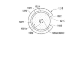
- FIGS. 19A to 23 are a perspective view and a top view of the handle attachment 1116 portion of the seventh embodiment.
- the handle attachment 1116 of this embodiment includes a disc-shaped tray 1021 whose upper surface is an article placement surface 1021a, and an annular grip handle 1020 that is disposed at a predetermined distance above the tray 1021.
- the grip handle 1020 is arranged so as to be concentric with the tray 1021, and a grip space portion 1025 is secured between the grip handle 1020 and the tray 1021.
- the inner peripheral surface of the grip handle 1020 is formed in a circular shape that is slightly larger than the outer peripheral surface of the tray 1021.
- the grip handle 1020 and the tray 1021 are connected to each other by a pair of connection posts arranged at opposite positions on the circumference.
- the grip handle 1020 and the tray 1021 are connected to each other.
- the two connecting columns 1122 are connected.
- the connecting strut 1122 is integrally formed with a trapezoidal bulging portion 1033 that bulges radially inward from the inner peripheral surface of the grip handle 1020 to a position reaching the outer peripheral edge of the tray 1021.
- An insertion hole 1023 through which the outer column 1003A of the column unit 1003 is inserted in the vertical direction is formed in the protruding unit 1033 and a portion connected to the protruding unit 1033 on the tray 1021.
- the bulging portion 1033 constitutes at least a part of an attachment portion for attaching the handle attachment 1116 to the column portion 1003.
- the insertion hole 1023 is disposed at a position offset from the center position of the tray 1021.
- a fixing portion for pressing and fixing the handle attachment 1116 to the support column portion 1003 may be provided on the bulging portion 1033, but may be provided on the lower surface side of the tray 1021 as in the sixth embodiment.
- the handle attachment 1116 of this embodiment can obtain the same basic effect as that of the sixth embodiment. Further, since the grip handle 1020 is connected to the connection support column 1122 only at one place in the circumferential direction, an area that can be gripped without interfering with the connection support column 1122 when the operator grips the grip handle 1020 is expanded. The operability can be improved. Further, the appearance quality can be further improved.
- the handle attachment 1116 itself is made more compact. can do.
- the example in which the insertion hole 1023 is arranged at a position offset from the center position of the tray 1021 has been described, but the insertion hole 1023 may be arranged at the center position of the tray 1021 as in the modification shown in FIG. 19C. good.
- the tray 1021 and the grip handle 1020 are obliquely coupled by the coupling column 1122 without providing the bulging portion on the coupling column 1122.
- FIG. 20A is a top view of the handle attachment 1216 portion of the eighth embodiment.
- the handle attachment 1216 of this embodiment includes a disc-shaped tray 1021 whose upper surface is an article placement surface 1021a, a grip handle 1220 (guide member) that is spaced above the tray 1021 by a predetermined distance, and And a gripping space portion 1025 is secured between the gripping handle 1220 and the tray 1021.
- the grip handle 1220 is not a complete annular shape, but an arc shape with a part of a circle cut out.
- the grip handle 1220 is disposed so as to be concentric with the tray 1021.
- the arc ends on both sides of the grip handle 1220 and the center area of the arc are connected to the outer peripheral edge of the tray 1021 by three connecting columns 1022. Further, an insertion hole 1023 through which the column part 1003 is inserted is provided at a position offset from the center position of the tray 1021.
- the inner surface of the grip handle 1220 is formed in a circular shape that is slightly larger than the outer peripheral surface of the tray 1021.
- a concave space 1035 that is recessed in a substantially fan shape toward the outer peripheral surface of the tray 1021 when viewed from above is provided between the arc ends on both sides of the grip handle 1220.
- the handle attachment 1216 of this embodiment can obtain the same basic effects as those of the sixth embodiment.
- the grip handle 1220 is formed in a circular arc shape with a part of the circular shape cut out, and a concave space 1035 is provided between the circular arc ends on both sides thereof. Therefore, for example, when an infusion pump is connected to an infusion pack suspended on an infusion suspension and an infusion tube is connected to the patient via the infusion pump, the tubes drawn from the infusion pack are gripped. It can be pulled out through the concave space 1035 without interfering with the handle 1220. For this reason, the workability
- the insertion hole 1023 may be arranged at the center position of the tray 1021 as in the modification shown in FIG. 20B. good.
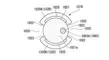
- FIG. 21A is a top view of the handle attachment 1316 portion of the ninth embodiment.
- the handle attachment 1316 of this embodiment includes a disc-shaped tray 1021 whose upper surface is an article placement surface 1021a, a grip handle 1320 (guide member) disposed at a predetermined distance above the tray 1021, and And a grip space portion 1025 is secured between the grip handle 1320 and the tray 1021.
- the grip handle 1320 includes a pair of arc-shaped handle pieces 1320A and 1320B. Both end portions of each handle piece 1320A, 1320B are connected to the outer peripheral edge portion of the tray 1021 by a connecting post 1022.
- a concave space 1035 is provided between each of adjacent handle pieces 1320A and 1320B.
- an insertion hole 1023 through which the support column 1003 is inserted in the vertical direction is provided at a position offset toward the one concave space 1035 with respect to the center position of the tray 1021.
- the handle attachment 1316 of this embodiment can basically obtain the same effects as those of the eighth embodiment. Furthermore, since the two concave spaces 1035 and 1035 are provided at opposite positions on the circumference of the grip handle 1320, it is possible to draw the tubes downward from a plurality of locations around the tray 1021 during the drip operation. Therefore, workability and convenience at the time of infusion can be further enhanced. Also in this embodiment, the insertion hole 1023 may be arranged at the center position of the tray 1021 as in the modification shown in FIG. 21B.
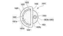
- FIG. 22 is a top view of the handle attachment 1416 portion of the tenth embodiment.
- the handle attachment 1416 of this embodiment includes a disc-shaped tray 1021 whose upper surface is an article placement surface 1021a, a grip handle 1420 (guide member) disposed at a predetermined distance above the tray 1021, and And a grip space portion 1025 is secured between the grip handle 1420 and the tray 1021.
- an insertion hole 1023 through which the column part 1003 is inserted in the vertical direction is provided at a position offset from the center position of the tray 1021.
- the grip handle 1420 is formed in a substantially D shape having a semicircular arc portion 1420a and linear portions 1420b that linearly connect both ends of the arc portion 1420a.
- the grip handle 1420 is disposed at a position offset outward from the upper column portion 1003 of the tray 1021.
- the arcuate portion 1420a of the grip handle 1420 is formed with an outer diameter that is slightly larger than the outer diameter of the tray 1021, and is connected to the outer peripheral edge portion of the tray 1021 by three connecting columns 1022 so as to be concentric with the center of the tray 1021. ing.
- the linear portion 1420b of the grip handle 1420 is disposed so as to cross over the tray 1021 at a position offset to the outside of the support column 1003.
- a substantially semicircular space 1435 is provided outside the straight portion 1420 b of the grip handle 1420.
- the handle attachment 1416 of this embodiment can basically obtain the same effects as those of the eighth and ninth embodiments.
- the grip handle 1420 is formed in a substantially D shape, a support column 1003 is disposed outside the grip handle 1420, and a substantially semicircular space 1435 is provided outside the grip handle 1420. Therefore, a larger space for pulling out the tubes downward can be secured at a position adjacent to the outside of the grip handle 1420, and the articles placed on the article placement surface 1021a of the tray 1021 Interference can be prevented.
- FIG. 23 is a perspective view of the handle attachment 1616 portion of the eleventh embodiment.
- the handle attachment 1616 of this embodiment includes a disc-shaped tray 1621 on which an article can be placed on the upper surface side, and an annular grip handle 1620 disposed at a predetermined distance below the tray 1621.
- the holding space portion 1025 is secured between the holding handle 1620 and the tray 1621.
- the grip handle 1620 is arranged so as to be concentric with the tray 1621, and is connected to the outer peripheral edge portion of the tray 1621 by a pair of connecting columns 1622 (connecting portions) arranged at opposing positions on the circumference of the tray 1621. Yes.
- the inner peripheral surface of the grip handle 1620 is formed larger than the outer peripheral surface of the tray 1621. Further, an insertion hole 1023 through which the support column 1003 is inserted is provided on the tray 1621 at a position offset from the center position. A boss 1624 for attaching the handle attachment 1616 to the support column 1003 is provided on the lower surface of the tray 1621. Is provided.
- an annular flange 1621b is provided on the outer peripheral side on the upper surface side of the tray 1621, and a concave article placement surface 1621a is provided inside the flange 1621b. Further, the upper surface of the flange portion 1621b is formed to be substantially horizontal.
- the handle attachment 1616 of this embodiment since the grip space 1025 is provided between the grip handle 1620 and the tray 1621 disposed on the upper side, the operator can move the drip stand.
- the grip handle 1620 portion can be gripped. Further, an article such as a cup can be placed on the article placement surface of the tray 1621. Furthermore, since the upper surface of the flange portion 1621b of the tray 1621 is formed substantially horizontally, an enlarged article such as an infusion pack P can be placed on the upper surface of the flange portion 1621b.
- the tray 1621 and the grip handle 1620 are coupled by the coupling column 1622, and the boss portion 1624 for attaching to the column unit 1003 is integrally provided on the lower surface of the tray 1621. And the grip handle function unit can be integrated together compactly and easily attached around the support column 1003. Also in this embodiment, the insertion hole 1023 may be provided at the center position of the tray 1621.
- the tray portion of the handle attachment is attached to the support column, but the handle body portion is not attached to the support column, but the tray portion and the handle body portion are both attached. It is also possible to make it attachable to a support
- an infusion stand that can improve convenience and operability without deteriorating appearance or increasing occupied space.
- an infusion stand and an infusion stand attachment that can improve convenience and operability without deteriorating the appearance or complicating the mounting work. Can do.
Landscapes
- Health & Medical Sciences (AREA)
- Vascular Medicine (AREA)
- Engineering & Computer Science (AREA)
- Anesthesiology (AREA)
- Biomedical Technology (AREA)
- Heart & Thoracic Surgery (AREA)
- Hematology (AREA)
- Life Sciences & Earth Sciences (AREA)
- Animal Behavior & Ethology (AREA)
- General Health & Medical Sciences (AREA)
- Public Health (AREA)
- Veterinary Medicine (AREA)
- Medical Preparation Storing Or Oral Administration Devices (AREA)
- Infusion, Injection, And Reservoir Apparatuses (AREA)
Abstract
この点滴スタンドは、物品が載置可能な物品載置面を有するトレーと、前記トレーの前記物品載置面の少なくとも一部の上方に配置され前記トレー上に載置された物品の落下を規制するガイド部材と、を備え、前記トレーと前記ガイド部材とが直接若しくは間接的に支柱部に連結され、前記ガイド部材と前記トレーとの間に、操作者が前記ガイド部材を把持ハンドルとして把持可能な把持空間部が設けられている。上記構造により、見栄えの低下や占有スペースの増大を招くことなく、利便性の向上と操作性の向上を図ることのできる点滴スタンドを提供することができる。
Description
本発明は、病院、介護施設、自宅等において患者に点滴を行う際等に用いられる点滴スタンド、及び、点滴スタンド用のアタッチメントに関する。
本願は、2013年5月31日に日本に出願された特願2013-116002号、および、2013年5月31日に日本に出願された特願2013-116003号に基づき優先権を主張し、その内容をここに援用する。
本願は、2013年5月31日に日本に出願された特願2013-116002号、および、2013年5月31日に日本に出願された特願2013-116003号に基づき優先権を主張し、その内容をここに援用する。
病院や介護施設、自宅等において、患者に対する治療活動として点滴を打つケースが多く見られる。点滴は、輸液パックを患者よりも高い位置に配置し、重力を利用して輸液パック内の輸液を患者の体内に送るという仕組みである。したがって、輸液パックを患者の上方に支持しておく点滴スタンドを用いるのが一般的である。
こうした点滴スタンドの基本構成としては、床面上に載置される脚部に、上下方向に沿って延出する支柱部が取り付けられ、その支柱部の上端部に輸液吊り下げ具が取り付けられているのが一般的である(例えば、特許文献1~3参照)。
特許文献1~3に記載の点滴スタンドは、輸液吊り下げ具が、支柱部の上端から略水平方向に延出する一対のアーム部と、各アーム部の先端部に設けられて輸液パックを直接吊り下げるためのフック部と、を備えた構成とされている。また、これらの点滴スタンドは、いずれも患者や看護師等が必要に応じてスタンドを自由に移動できるように脚部にキャスタが設けられている。
使い勝手を向上させるために、移動する際の患者の所有物を載置する面や、輸液パックを吊り下げる作業時の作業面として、点滴スタンドにトレー(物品載置台)が設けられているのが望ましい。このような構成とした場合には、点滴スタンドの利便性をより向上させることができる。
特許文献1~3に記載の点滴スタンドは、輸液吊り下げ具が、支柱部の上端から略水平方向に延出する一対のアーム部と、各アーム部の先端部に設けられて輸液パックを直接吊り下げるためのフック部と、を備えた構成とされている。また、これらの点滴スタンドは、いずれも患者や看護師等が必要に応じてスタンドを自由に移動できるように脚部にキャスタが設けられている。
使い勝手を向上させるために、移動する際の患者の所有物を載置する面や、輸液パックを吊り下げる作業時の作業面として、点滴スタンドにトレー(物品載置台)が設けられているのが望ましい。このような構成とした場合には、点滴スタンドの利便性をより向上させることができる。
また、点滴スタンドを移動させる際には、点滴スタンドの支柱部と一体に形成される把持ハンドルが設けられることが望ましい。このような把持ハンドルを備えた点滴スタンドが従来より案出されている(例えば、特許文献2参照)。
特許文献2に記載の点滴スタンドには、円環状のハンドル本体と、支柱部の外面に固定されるボス部と、ボス部とハンドル本体を連結する連結部とによって構成される把持ハンドルが設けられている。この特許文献2に記載の点滴スタンドにおいては、支柱部の周囲のいずれの方向からでも把持ハンドルを把持してスタンドを移動させることができる。また、複数人で把持ハンドルを把持してスタンドを操作することもできる。このため、点滴スタンドとしての操作性が良好である。
特許文献2に記載の点滴スタンドには、円環状のハンドル本体と、支柱部の外面に固定されるボス部と、ボス部とハンドル本体を連結する連結部とによって構成される把持ハンドルが設けられている。この特許文献2に記載の点滴スタンドにおいては、支柱部の周囲のいずれの方向からでも把持ハンドルを把持してスタンドを移動させることができる。また、複数人で把持ハンドルを把持してスタンドを操作することもできる。このため、点滴スタンドとしての操作性が良好である。
ところで、点滴スタンドの利便性と操作性を高めるために、点滴スタンドの支柱部に、上記のようなトレーと把持ハンドルとを設けることが考えられる。しかし、単純にトレーと把持ハンドルとを支柱部上の離間した部位に別々に設けた場合、支柱部からの張り出し部位が支柱部の離間した箇所に複数でき、見栄えが低下する可能性がある。
また、物品を載置するトレー上には、載置した物品の落下を規制する規制部があることが望ましい。このため、上記のようにトレーと把持ハンドルとを支柱部上の離間した部位に別々に設ける場合にも、トレーに規制部を設けることが考えられる。しかし、この場合、規制部を備えたトレーを採用すると、上述のように見栄えが低下するばかりでなく、支柱部上でのトレーの占有スペースが大きくなってしまう。
また、物品を載置するトレー上には、載置した物品の落下を規制する規制部があることが望ましい。このため、上記のようにトレーと把持ハンドルとを支柱部上の離間した部位に別々に設ける場合にも、トレーに規制部を設けることが考えられる。しかし、この場合、規制部を備えたトレーを採用すると、上述のように見栄えが低下するばかりでなく、支柱部上でのトレーの占有スペースが大きくなってしまう。
また、トレーと把持ハンドルとを支柱部上の離間した部位に別々に設ける場合、これらの取付作業が煩雑になってしまう。
そこで本発明は、見栄えの低下や占有スペースの増大を招くことなく、利便性の向上と操作性の向上を図ることのできる点滴スタンドを提供することを目的とする。
また、本発明は、見栄えの低下や取付作業の煩雑化を招くことなく、利便性の向上と操作性の向上を図ることのできる点滴スタンド、及び、点滴スタンド用のアタッチメントを提供することを目的とする。
本発明では、上記課題を解決するために以下の構成を採用した。
本発明の第一の態様は、上下方向に延びる支柱部に、輸液パックが輸液吊り下げ具を介して吊り下げ支持される点滴スタンドであって、物品が載置可能な物品載置面を有するトレーと、前記トレーの前記物品載置面の少なくとも一部の上方に配置され前記トレー上に載置された物品の落下を規制するガイド部材と、を備え、前記トレーと前記ガイド部材とが直接若しくは間接的に前記支柱部に連結され、前記ガイド部材と前記トレーとの間に、操作者が前記ガイド部材を把持ハンドルとして把持可能な把持空間部が設けられている。
これにより、トレー上の物品載置面に物品を載せ置くと、その物品の落下がガイド部材によって規制される。また、患者や看護師等の操作者は、トレーの上方のガイド部材を把持ハンドルとして把持することにより、点滴スタンドを操作できる。また、トレーとガイド部材とが支柱部の上下方向で大きく離間して配置されることがなくなる。
本発明の第二の態様は、上記第一の態様に係る点滴スタンドにおいて、前記トレーには、前記支柱部が上下方向に挿通される挿通孔が設けられている。この場合、支柱部がトレーの外側に配置されないことから、支柱部からのトレーの張り出し量が小さく抑えられる。
本発明の第三の態様は、上記第二の態様に係る点滴スタンドにおいて、前記挿通孔は、上面視で、前記トレーの中心からオフセットした位置に設けられる。この場合、トレー上に支柱部と干渉しない纏まった物品載置スペースを確保することが可能になる。
本発明の第四の態様は、上記第一ないし第三の態様に係る点滴スタンドにおいて、前記トレーの外周縁部に沿う上方位置に前記ガイド部材が配設される。
この場合、トレーの上面のほぼ全域を物品載置面として利用することが可能になる。
この場合、トレーの上面のほぼ全域を物品載置面として利用することが可能になる。
本発明の第五の態様は、上記第四の態様に係る点滴スタンドにおいて、前記ガイド部材の内周面は、上面視で、前記トレーの外周面よりも外側、若しくは、略同一位置となるように形成される。この場合、ガイド部材が平面視でトレーよりも内側に位置しないことから、トレーの上面のほぼ全域を物品載置面として有効利用することが可能になる。また、操作者がガイド部材を把持ハンドルとして把持するときに、トレーが邪魔になりにくくなる。
本発明の第六の態様は、上記第一ないし第五の態様に係る点滴スタンドにおいて、前記ガイド部材は、上面視で、前記トレーの外縁形状と相似形状をなすように形成される。この場合、外観バランスが良好になり、外部からの見栄えが低下しない。
本発明の第七の態様は、上記第一ないし第六の態様に係る点滴スタンドにおいて、前記ガイド部材は、上面視で、環状をなすように形成される。この場合、操作者がガイド部材を把持ハンドルとして把持するときに、いずれの方向からもガイド部材を把持することが可能になる。
本発明の第八の態様は、上下方向に延びる支柱部に、輸液パックが輸液吊り下げ具を介して吊り下げ支持される点滴スタンドであって、物品が載置可能な物品載置面を有するトレーと、前記トレーとの間に操作者が把持し得る把持空間部を確保するように離間して配置される把持ハンドルと、前記トレーと前記把持ハンドルを連結する連結部と、前記トレーと前記把持ハンドルの少なくともいずれか一方を前記支柱部に取り付ける取付部と、を有するアタッチメントを備えている。
これにより、トレー上の物品載置面には物品を載せ置くことが可能になり、患者や看護師等の操作者は、把持ハンドルを把持して点滴スタンドを操作することが可能になる。また、トレーと把持ハンドルは、一体のアタッチメントとして取付部を介して支柱部に取り付けることが可能になる。
これにより、トレー上の物品載置面には物品を載せ置くことが可能になり、患者や看護師等の操作者は、把持ハンドルを把持して点滴スタンドを操作することが可能になる。また、トレーと把持ハンドルは、一体のアタッチメントとして取付部を介して支柱部に取り付けることが可能になる。
本発明の第九の態様は、上記第八の態様に係る点滴スタンドにおいて、前記取付部は、前記連結部に設けられる。この場合、アタッチメント全体をよりコンパクト化することが可能になり、外観が良好になる。
本発明の第十の態様は、上記第八または第九の態様に係る点滴スタンドにおいて、前記トレーには、前記支柱部が上下方向に挿通される挿通孔が設けられている。この場合、支柱部がトレーの外側に配置されないことから、支柱部からのトレーの張り出し量が小さく抑えられる。
本発明の第十一の態様は、上記第八ないし第十の態様に係る点滴スタンドにおいて、前記把持ハンドルは、上面視で、前記トレーの外縁形状と相似形状をなすように形成される。この場合、外観バランスが良好になり、外部からの見栄えが低下しない。
本発明の第十二の態様は、上記第八ないし第十一の態様に係る点滴スタンドにおいて、前記把持ハンドルは、上面視で、環状をなすように形成される。この場合、操作者が把持ハンドルを把持するときに、いずれの方向からも把持ハンドルを把持することが可能になる。
本発明の第十三の態様は、点滴スタンドの上下方向に延びる支柱部に取り付けられる点滴スタンド用のアタッチメントであって、物品が載置可能な物品載置面を有するトレーと、前記トレーとの間に操作者が把持し得る把持空間部を確保するように離間して配置される把持ハンドルと、前記トレーと前記把持ハンドルを連結する連結部と、前記トレーと前記把持ハンドルの少なくともいずれか一方を前記支柱部に取り付ける取付部と、を備えている。
本発明によれば、トレーの所定距離上方側のガイド部材を、物品の落下を規制する規制部と把持ハンドルの双方として機能させることができる。したがって、トレーと把持ハンドルが支持軸上で離間して配置されることによる見栄えの低下や占有スペースの増大を招くことなく、トレー上へ物品を容易に載置し、かつ、操作者がガイド部材を把持して点滴スタンドを容易に操作することができる。
また、本発明によれば、トレーと把持ハンドルとを、一体のアタッチメントとして支柱部にコンパクトに取り付けることができる。したがって、見栄えの低下や取付作業の煩雑化を招くことなく、トレー上へ物品を容易に載置し、かつ、操作者が把持ハンドルを把持して点滴スタンドを容易に操作することができる。
(第1の実施形態)
以下、本発明の実施形態を図面に基づいて説明する。
最初に、図1~図6に示す第1の実施形態について説明する。なお、以下で説明する各実施形態やその変形例においては、同一部分に同一符号を付して重複する説明を省略するものとする。
図1,図2は、この実施形態に係る点滴スタンド1の外観を示す斜視図である。
点滴スタンド1は、病院や介護施設、自宅等の床面上に載置される脚部ブロック2と、脚部ブロック2に支持されて上下方向に沿って延出する支柱部3と、支柱部3の上端部に取り付けられ、輸液パックPを吊り下げ支持する輸液吊り下げ具4と、を備えている。
以下、本発明の実施形態を図面に基づいて説明する。
最初に、図1~図6に示す第1の実施形態について説明する。なお、以下で説明する各実施形態やその変形例においては、同一部分に同一符号を付して重複する説明を省略するものとする。
図1,図2は、この実施形態に係る点滴スタンド1の外観を示す斜視図である。
点滴スタンド1は、病院や介護施設、自宅等の床面上に載置される脚部ブロック2と、脚部ブロック2に支持されて上下方向に沿って延出する支柱部3と、支柱部3の上端部に取り付けられ、輸液パックPを吊り下げ支持する輸液吊り下げ具4と、を備えている。
脚部ブロック2は、支柱部3の下端を保持するボス部10の外周側に放射状に延びる5本の脚フレーム11と、各脚フレーム11の延出端に取り付けられるキャスタ12と、を有する。したがって、この実施形態の脚部ブロック2は、キャスタ12を介して床面上を移動可能である。なお、この実施形態の場合、実際にはボス部10や脚フレーム11の上方側が樹脂製のカバー部材13によって覆われているが、図1,図2においては、図示都合上、カバー部材13上のボス部10や脚フレーム11に対応する箇所に符号10,11を付している。
この実施形態の場合、支柱部3は、下端が脚部ブロック2に取り付けられる中空状のアウタ支柱3Aと、上端に輸液吊り下げ具4が取り付けられる中空状のインナ支柱3Bと、を備え、インナ支柱3Bの下部領域がアウタ支柱3Aの上部に摺動自在に嵌入されている。支柱部3の内部には、アウタ支柱3Aとインナ支柱3Bの相対位置を固定するための図示しないロック機構が装備される。ロック機構を解除することにより、アウタ支柱3Aとインナ支柱3Bの相対位置(支柱部3の伸縮長さ)を適宜調整できる。
インナ支柱3Bの上下方向の略中間部には、ロック機構を解除操作するための解除操作スリーブ14が設置されている。解除操作スリーブ14は、インナ支柱3Bの内部においてロック機構のロック解除片に接続される。看護師等の操作者によって上方にスライド操作されたときにロック機構を解除し、下方に戻し操作されたときにロック機構を再度ロック状態に維持する。
また、この実施形態では、アウタ支柱3Aには、荷掛けフックアタッチメント15と、ハンドルアタッチメント16(点滴スタンド用のアタッチメント)が昇降調整可能に取り付けられている。
荷掛けフックアタッチメント15は、アウタ支柱3Aの外周面に対して締結固定可能なボス部17と、ボス部17から相反方向に延出する一対のフック部18,18と、を備え、各フック部18にウロバッグや手荷物19等を適宜吊り下げ支持できる。ハンドルアタッチメント16については後に詳述する。
荷掛けフックアタッチメント15は、アウタ支柱3Aの外周面に対して締結固定可能なボス部17と、ボス部17から相反方向に延出する一対のフック部18,18と、を備え、各フック部18にウロバッグや手荷物19等を適宜吊り下げ支持できる。ハンドルアタッチメント16については後に詳述する。
輸液吊り下げ具4は、支柱部3のインナ支柱3Bの上端部に締結固定されるボス部27と、支柱部3の軸心o回りを取り囲むように上下方向に沿って立設された略方形筒状の周壁28と、ボス部27と周壁28を連結する連結支柱29と、周壁28の下端部の外側面から外側(支柱部3の軸心oの位置される側と逆側)に突出する4つの吊り下げ支持片30…と、を備えている。
周壁28は、左右方向の両側の縁部が円弧状に丸みをおびた4つの支持壁31…が方形状に配置され、隣接する支持壁31,31同士が相互に連結するよう形成される。この実施形態の場合、周壁28全体が硬質の樹脂材料によって方形筒状に一体に形成されている。各支持壁31の外面31a(支柱部3の軸心oの位置される側と逆側の面)は幅方向の中央領域を中心としてほぼ平坦に形成されている。
連結支柱29は、各支持壁31の下縁の幅方向の中央位置とボス部27の外面とを連結するように計4つ設けられている。吊り下げ支持片30は、金属製の板材によって断面略L字状に形成される。L字の一辺は対応する支持壁31の下縁の幅方向の中央位置に取り付けられ、L字の他辺は上方に向かって延びる。吊り下げ支持片30のL字の一辺の先端部は対応する支持壁31と連結支柱29に挿し込まれ、連結支柱29に固定されている。各吊り下げ支持片30には、図1に示すように、輸液パックPの吊り下げ孔7が係合可能とされている。なお、図1中の符号8aは、吊り下げ孔7が形成されている輸液パックPの上シール部であり、符号9は、図示しない点滴チューブが接続される輸液パックPの注出筒である。
図3,図4は、ハンドルアタッチメント16部分を示す斜視図であり、図5は、支柱部3を破断して示すハンドルアタッチメント16部分の上面図である。また、図6は、一部を断面にしたハンドルアタッチメント16部分の側面図である。
ハンドルアタッチメント16は、上面にカップ等の日用品やその他の物品26を載置可能なトレー21と、トレー21の上方側に所定距離離間して配置される円環状の把持ハンドルであるハンドル本体20(ガイド部材)と、トレー21とハンドル本体20を連結する一対の連結支柱22,22(連結部)と、アウタ支柱3Aの外周面に対して締結固定可能なボス部24(取付部)と、を備えている。
ハンドルアタッチメント16は、上面にカップ等の日用品やその他の物品26を載置可能なトレー21と、トレー21の上方側に所定距離離間して配置される円環状の把持ハンドルであるハンドル本体20(ガイド部材)と、トレー21とハンドル本体20を連結する一対の連結支柱22,22(連結部)と、アウタ支柱3Aの外周面に対して締結固定可能なボス部24(取付部)と、を備えている。
トレー21は、ハンドル本体20の内周面よりも一回り小さい円形の平板状に形成され、その上面が物品26を載せ置くための物品載置面21aとされている。トレー21は、ハンドル本体20の下方側に、ハンドル本体20と同軸に配置され、トレー21の外周上の対向する位置において、連結支柱22,22によってハンドル本体20に連結されている。連結支柱22は、トレー21の外周側の上面とハンドル本体20の内周側の下面を連結するように傾斜して配置されている。トレー21には、その中心部からオフセットした位置に、上下に貫通する挿通孔23が設けられ、挿通孔23にアウタ支柱3Aが挿通される。
この実施形態の場合、トレー21と連結支柱22,22とハンドル本体20とは、ボス部24の一部とともに硬質樹脂によって一体に形成されている。
この実施形態の場合、トレー21と連結支柱22,22とハンドル本体20とは、ボス部24の一部とともに硬質樹脂によって一体に形成されている。
また、ボス部24は、トレー21の下面の挿通孔23と同軸となる位置に設けられている。ボス部24は、トレー21の下面から突出するよう設けられた半割円筒状の内筒24aと、内筒24aの外側に被着される外筒24bとから構成されている。内筒24aは、半割部を中心として径方向内側に変形可能であり、外周面に雄ねじ50が設けられている。一方、外筒24bは、内筒24aの雄ねじ50と螺合可能な雌ねじ51を備え、内筒24aの雄ねじ50に締め込むことによって、内筒24aを支柱部3(アウタ支柱3A)の外周面に圧接固定できる。したがって、ボス部24の外筒24bの締め込みを緩めることによって、ハンドルアタッチメント16は支柱部3(アウタ支柱3A)上を移動可能であり、所望の位置で外筒24bを再度締め込むことによってハンドルアタッチメント16を支柱部3(アウタ支柱3A)に対して固定することができる。
なお、この実施形態の場合、トレー21はボス部24を介して支柱部3に直接連結され、ハンドル本体20(ガイド部材)は、トレー21を介して支柱部3に間接的に連結されている。
なお、この実施形態の場合、トレー21はボス部24を介して支柱部3に直接連結され、ハンドル本体20(ガイド部材)は、トレー21を介して支柱部3に間接的に連結されている。
ここで、一対の連結支柱22,22によってトレー21に連結されたハンドル本体20の下方には、操作者がハンドル本体20を把持するのに充分な把持空間部25が確保されている。このため、患者や看護師等の操作者は、脚部ブロック2のキャスタ12がロックされていなければ、ハンドル本体20を把持して点滴スタンド1を自由な方向に移動させることができる。
また、ハンドル本体20とトレー21との間に把持空間部25が確保されているものの、トレー21の上面からハンドル本体20までの高さが、カップ等の患者が日常一般に使用する物品26の高さよりも低く設定されているため、ハンドル本体20はトレー21上に載置された物品26の落下を規制するガイド部材(規制部)としても機能する。この実施形態の場合、アウタ支柱3Aが挿通されるトレー21上の挿通孔23がトレー21の中心からオフセットした位置に配置されているため、トレー21上には、アウタ支柱3Aと干渉することのない充分な物品配置スペースが確保されている。
また、この実施形態では、ハンドル本体20の上面は全域が略水平になるように形成されているため、必要に応じてハンドル本体20の上面にも点滴パックP等の大型の物品を載置することも可能となっている。
また、この実施形態では、ハンドル本体20の上面は全域が略水平になるように形成されているため、必要に応じてハンドル本体20の上面にも点滴パックP等の大型の物品を載置することも可能となっている。
以上のようにこの実施形態に係る点滴スタンド1においては、支柱部3に取り付けられるハンドルアタッチメント16に、物品載置面21aを有する平板状のトレー21と、トレー21の物品載置面21aの上方を取り囲むように配置される環状のガイド部材であるハンドル本体20と、が設けられ、ハンドル本体20とトレー21の間に把持空間部25が確保されている。したがって、物品26の載置機能部と把持ハンドル機能部とをコンパクトに集約して支柱部3回りに設置することができる。このため、この実施形態の点滴スタンド1においては、支柱部3回りの見栄えの低下や占有スペースの増大を招くことなく、支柱部3回りへの物品26の載置と、移動時等における操作者による確実な把持との双方を実現することができる。
また、特に、この点滴スタンド1においては、ハンドル本体20が、トレー21の物品載置面21a上に載置した物品26の落下を規制するガイド部材(規制部)としても機能するため、トレー21上に物品26を載置した際の利便性をより高めることができる。したがって、この点滴スタンド1の場合、ハンドルアタッチメント16が物品26の落下規制機能を備えながらも、占有スペースの増大を抑え、全体の見栄え低下も良好にすることができる。
また、特に、この点滴スタンド1においては、ハンドル本体20が、トレー21の物品載置面21a上に載置した物品26の落下を規制するガイド部材(規制部)としても機能するため、トレー21上に物品26を載置した際の利便性をより高めることができる。したがって、この点滴スタンド1の場合、ハンドルアタッチメント16が物品26の落下規制機能を備えながらも、占有スペースの増大を抑え、全体の見栄え低下も良好にすることができる。
また、トレー21の側方から延びる連結アーム等により、ハンドルアタッチメント16のトレー21を支柱部3の外側に配置することも可能であるが、この実施形態の点滴スタンド1においては、ハンドルアタッチメント16のトレー21に挿通孔23を設け、支柱部3が挿通孔23に挿通されるため、支柱部3からのトレー21の張り出し量をより小さくすることができる。したがって、この点滴スタンド1では、点滴スタンドとしての利便性と見栄えをより高めることができる。
さらに、この実施形態の点滴スタンド1においては、挿通孔23が、上面視でトレー21の中心位置からオフセットした位置に設けられているため、トレー21上に支柱部3と干渉しない纏まった物品載置スペースを確保することができる。このため、この点滴スタンド1では、トレー21上への物品26の載置し易さを確保しつつ、トレー21の張り出し量を抑制することができる。
ただし、ハンドルアタッチメント16は、必ずしも、トレー21の中心位置からオフセットした位置に挿通孔23を設けなければならないものではなく、図7に示す変形例のように、挿通孔23をトレー21の中心位置に設けることも可能である。
ただし、ハンドルアタッチメント16は、必ずしも、トレー21の中心位置からオフセットした位置に挿通孔23を設けなければならないものではなく、図7に示す変形例のように、挿通孔23をトレー21の中心位置に設けることも可能である。
また、ハンドルアタッチメント16のハンドル本体20は、トレー21の物品載置面21aの少なくとも一部の上方に配置されていれば、必ずしもトレー21の外周縁部に沿うようにトレー21の上方位置に配置されていなくても良い。しかしながら、この実施形態の点滴スタンド1は、ハンドル本体20がトレー21の外周縁部に沿うようにトレー21の上方位置に配置されていることから、トレー21の上面上の広い領域を物品載置面21aとして有効に利用することができる。
特に、この実施形態の場合、ハンドルアタッチメント16のハンドル本体20が、上面視で、ハンドル本体20の内周面がトレー21の外周面よりも外側となるように配置されているため、トレー21の上面のほぼ全域を物品載置面21aとして有効利用することができる。さらに、操作者がハンドル本体20を把持ハンドルとして把持するときに、トレー21が邪魔になりにくくなるという利点がある。
なお、ハンドル本体20は、上面視で、ハンドル本体20の内周面がトレー21の外周面と略同一位置となるように形成しても良い。
特に、この実施形態の場合、ハンドルアタッチメント16のハンドル本体20が、上面視で、ハンドル本体20の内周面がトレー21の外周面よりも外側となるように配置されているため、トレー21の上面のほぼ全域を物品載置面21aとして有効利用することができる。さらに、操作者がハンドル本体20を把持ハンドルとして把持するときに、トレー21が邪魔になりにくくなるという利点がある。
なお、ハンドル本体20は、上面視で、ハンドル本体20の内周面がトレー21の外周面と略同一位置となるように形成しても良い。
また、この実施形態の点滴スタンド1においては、トレー21の上方に配置されるハンドルアタッチメント16のハンドル本体20がトレー21の外縁形状と相似形状に形成されているため、外観バランスが良好であり、外部からの見栄えが低下しない。
また、ハンドルアタッチメント16のハンドル本体20は、トレー21の物品載置面21aの少なくとも一部の上方に配置されていれば、必ずしも環状である必要はない。しかしながら、この実施形態の点滴スタンド1は、ハンドル本体20が環状に形成されているため、操作者がハンドル本体20を把持ハンドルとして把持するときに周域のいずれの方向からも把持でき、操作性が良いという利点がある。
(第2の実施形態)
つづいて、図8A~図11に示す他の実施形態について説明する。図8A~図11に示す各実施形態は、上述した第1の実施形態とハンドルアタッチメントの構造のみが異なり、他の部分は同様の構造となっている。
図8Aおよび8Bは、第2の実施形態のハンドルアタッチメント116部分の斜視図と上面図である。
この実施形態のハンドルアタッチメント116は、上面が物品載置面21aとされた円板状のトレー21と、トレー21の上方側に所定距離離間して配置される円環状のハンドル本体20(ガイド部材)と、を備える。ハンドル本体20はトレー21と同心となるように配置され、ハンドル本体20とトレー21の間に把持空間部25が確保されている。この実施形態の場合も、ハンドル本体20の内周面は、トレー21の外周面よりも一回り大きい円形形状に形成されている。第1の実施形態では、ハンドル本体20とトレー21は、円周上の対向する位置に配置される一対の連結支柱によって連結されていたが、この実施形態では、ハンドル本体20とトレー21が一つの連結支柱122によって連結されている。
連結支柱122には、ハンドル本体20の内周面から、トレー21の外周縁に達する位置まで径方向内側に膨出する台形状の膨出部33が一体に形成されている。膨出部33と、トレー21上の膨出部33に連結される部位とには、支柱部3のアウタ支柱3Aが上下方向に挿通される挿通孔23が形成される。膨出部33は、ハンドルアタッチメント116を支柱部3に取り付ける取付部の少なくとも一部を構成する。この実施形態の場合、挿通孔23はトレー21の中心位置からオフセットした位置に配置されている。なお、ハンドルアタッチメント116を支柱部3に圧接固定するための固定部は、膨出部33に設けても良いが、第1の実施形態と同様にトレー21の下面側に設けても良い。
この実施形態の点滴スタンドは、第1の実施形態と同様の基本的な効果を得ることができる。さらに、ハンドルアタッチメント116のハンドル本体20が円周方向の一箇所のみで連結支柱122によって連結されているため、ハンドル本体20を操作者が把持ハンドルとして把持するときに、連結支柱122と干渉せずに把持できる領域を拡張して操作性を高めることができる。また、外観品質をより高めることができる。
さらに、この実施形態の場合、ハンドル本体20とトレー21を連結する連結支柱122に、ハンドルアタッチメント116を支柱部3に取り付ける取付部の少なくとも一部を構成する膨出部33が設けられているため、ハンドルアタッチメント116自体をよりコンパクト化することができる。
なお、ここでは、挿通孔23をトレー21の中心位置からオフセットした位置に配置する例について説明したが、図8Cに示す変形例のように挿通孔23をトレー21の中心位置に配置しても良い。この変形例の場合、連結支柱122には膨出部を設けずに、連結支柱122によってトレー21とハンドル本体20を斜めに連結する。
なお、ここでは、挿通孔23をトレー21の中心位置からオフセットした位置に配置する例について説明したが、図8Cに示す変形例のように挿通孔23をトレー21の中心位置に配置しても良い。この変形例の場合、連結支柱122には膨出部を設けずに、連結支柱122によってトレー21とハンドル本体20を斜めに連結する。
(第3の実施形態)
図9Aは、第3の実施形態のハンドルアタッチメント216部分の上面図である。
この実施形態のハンドルアタッチメント216は、上面が物品載置面21aとされた円板状のトレー21と、トレー21の上方側に所定距離離間して配置されるハンドル本体220(ガイド部材)と、を備え、ハンドル本体220とトレー21の間に把持空間部25が確保されている。ただし、この実施形態の場合、ハンドル本体220は完全な円環形状ではなく、円形の一部が切欠かれた円弧形状とされている。ハンドル本体220は、トレー21と同心となるように配置される。ハンドル本体220の両側の円弧端と円弧の中央領域が3つの連結支柱22によってトレー21の外周縁部に連結されている。また、トレー21の中心位置からオフセットした位置に、支柱部3が挿通される挿通孔23が設けられている。ハンドル本体220の内面は、トレー21の外周面よりも一回り大きい円形形状に形成されている。
また、ハンドル本体220の両側の円弧端の間には、上面視で、トレー21の外周面に向かって略扇状に窪む凹状空間35が設けられている。
この実施形態の点滴スタンドは、第1の実施形態と同様の基本的な効果を得ることができる。さらに、ハンドルアタッチメント216のハンドル本体220が、円形の一部が切欠かれた円弧形状に形成され、その両側の円弧端の間に凹状空間35が設けられている。したがって、例えば、輸液吊り下げ具に吊り下げられた輸液パックに輸液ポンプを接続し、輸液ポンプを介して患者に点滴チューブを接続するような場合に、輸液パックから引き出されたチューブ類を、ハンドル本体220と干渉することなく凹状空間35を通して下方に引き出すことができる。このため、点滴時における作業性と利便性をより高めることができる。
なお、ここでは、挿通孔23をトレー21の中心位置からオフセットした位置に配置する例について説明したが、図9Bに示す変形例のように挿通孔23をトレー21の中心位置に配置しても良い。
なお、ここでは、挿通孔23をトレー21の中心位置からオフセットした位置に配置する例について説明したが、図9Bに示す変形例のように挿通孔23をトレー21の中心位置に配置しても良い。
(第4の実施形態)
図10Aは、第4の実施形態のハンドルアタッチメント316部分の上面図である。
この実施形態のハンドルアタッチメント316は、上面が物品載置面21aとされた円板状のトレー21と、トレー21の上方側に所定距離離間して配置されるハンドル本体320(ガイド部材)と、を備え、ハンドル本体320とトレー21の間に把持空間部25が確保されている。ハンドル本体320は、円弧状の一対のハンドル片320A,320Bから成る。各ハンドル片320A,320Bの両端部が連結支柱22によってトレー21の外周縁部に連結されている。この実施形態では、隣接するハンドル片320A,320Bの各間に凹状空間35が設けられている。トレー21上には、支柱部3が上下方向に挿通される挿通孔23が、トレー21の中心位置に対して一方の凹状空間35側にオフセットした位置に設けられている。
この実施形態の点滴スタンドは、基本的に第3の実施形態と同様の効果を得ることができる。さらに、ハンドル本体320の円周上の対向する位置に二つの凹状空間35,35が設けられているため、点滴作業時等にトレー21回りの複数個所からチューブ類を下方に引き出すことが可能になるため、点滴時における作業性と利便性をより高めることができる。
なお、この実施形態の場合も、図10Bに示す変形例のように挿通孔23をトレー21の中心位置に配置しても良い。
なお、この実施形態の場合も、図10Bに示す変形例のように挿通孔23をトレー21の中心位置に配置しても良い。
(第5の実施形態)
図11は、第5の実施形態のハンドルアタッチメント416部分の上面図である。
この実施形態のハンドルアタッチメント416は、上面が物品載置面21aとされた円板状のトレー21と、トレー21の上方側に所定距離離間して配置されるハンドル本体420(ガイド部材)と、を備え、ハンドル本体420とトレー21の間に把持空間部25が確保されている。トレー21上には、支柱部3が上下方向に挿通される挿通孔23が、トレー21の中心位置からオフセットした位置に設けられている。ハンドル本体420は、半円状の円弧部420aと、円弧部420aの両端部を直線状に連結する直線部420bと、を有する略D字状に形成される。ハンドル本体420は、トレー21の上方側の支柱部3から外側にオフセットした位置に配置されている。ハンドル本体420の円弧部420aは、トレー21の外径よりも一回り大きい外径に形成され、トレー21の中心と同心となるように3つの連結支柱22によってトレー21の外周縁部に連結されている。また、ハンドル本体420の直線部420bは、支柱部3の外側にオフセットした位置でトレー21の上方を横切るように配置されている。この実施形態では、ハンドル本体420の直線部420bの外側には略半円状の空間435が設けられている。
この実施形態の点滴スタンドは、基本的に第3,第4の実施形態とほぼ同様の効果を得ることができる。さらに、ハンドル本体420が略D字状に形成され、ハンドル本体420の外側に支柱部3が配置され、ハンドル本体420の外側に略半円状の空間435が設けられている。したがって、ハンドル本体420の外側に隣接する位置に、チューブ類を下方に引き出すためのスペースをより大きく確保することができ、トレー21の物品載置面21a上に載置した物品が支柱部3と干渉するのを防止することができる。
(第6の実施形態)
以下、この発明の実施形態を図面に基づいて説明する。
最初に、図12~図17に示す第6の実施形態について説明する。なお、以下で説明する各実施形態やその変形例においては、同一部分に同一符号を付して重複する説明を省略するものとする。
図12,図13は、この実施形態に係る点滴スタンド1001の外観を示す斜視図である。
点滴スタンド1001は、病院や介護施設、自宅等の床面上に載置される脚部ブロック1002と、脚部ブロック1002に支持されて上下方向に沿って延出する支柱部1003と、支柱部1003の上端部に取り付けられ、輸液パックPを吊り下げ支持する輸液吊り下げ具1004と、を備えている。
以下、この発明の実施形態を図面に基づいて説明する。
最初に、図12~図17に示す第6の実施形態について説明する。なお、以下で説明する各実施形態やその変形例においては、同一部分に同一符号を付して重複する説明を省略するものとする。
図12,図13は、この実施形態に係る点滴スタンド1001の外観を示す斜視図である。
点滴スタンド1001は、病院や介護施設、自宅等の床面上に載置される脚部ブロック1002と、脚部ブロック1002に支持されて上下方向に沿って延出する支柱部1003と、支柱部1003の上端部に取り付けられ、輸液パックPを吊り下げ支持する輸液吊り下げ具1004と、を備えている。
脚部ブロック1002は、支柱部1003の下端を保持するボス部1010の外周側に放射状に延びる5本の脚フレーム1011と、各脚フレーム1011の延出端に取り付けられるキャスタ1012と、を有する。したがって、この実施形態の脚部ブロック1002は、キャスタ1012を介して床面上を移動可能である。なお、この実施形態の場合、実際にはボス部1010や脚フレーム1011の上方側が樹脂製のカバー部材1013によって覆われているが、図12,図13においては、図示都合上、カバー部材1013上のボス部1010や脚フレーム1011に対応する箇所に符号1010,1011を付している。
この実施形態の場合、支柱部1003は、下端が脚部ブロック1002に取り付けられる中空状のアウタ支柱1003Aと、上端に輸液吊り下げ具1004が取り付けられる中空状のインナ支柱1003Bと、を備え、インナ支柱1003Bの下部領域がアウタ支柱1003Aの上部に摺動自在に嵌入されている。支柱部1003の内部には、アウタ支柱1003Aとインナ支柱1003Bの相対位置を固定するための図示しないロック機構が装備される。ロック機構を解除することにより、アウタ支柱1003Aとインナ支柱1003Bの相対位置(支柱部1003の伸縮長さ)を適宜調整できる。
インナ支柱1003Bの上下方向の略中間部には、前記ロック機構を解除操作するための解除操作スリーブ1014が設置されている。この解除操作スリーブ1014は、インナ支柱1003Bの内部においてロック機構のロック解除片に接続される。看護師等の操作者によって上方にスライド操作されたときにロック機構を解除し、下方に戻し操作されたときにロック機構を再度ロック状態に維持する。
また、この実施形態では、アウタ支柱1003Aには、荷掛けフックアタッチメント1015と、この実施形態に係る点滴スタンド用のアタッチメントであるハンドルアタッチメント1016が昇降調整可能に取り付けられている。
荷掛けフックアタッチメント1015は、アウタ支柱1003Aの外周面に対して締結固定可能なボス部1017と、ボス部1017から相反方向に延出する一対のフック部1018,1018と、を備え、各フック部1018にウロバッグや手荷物1019等を適宜吊り下げ支持できる。ハンドルアタッチメント1016については後に詳述する。
荷掛けフックアタッチメント1015は、アウタ支柱1003Aの外周面に対して締結固定可能なボス部1017と、ボス部1017から相反方向に延出する一対のフック部1018,1018と、を備え、各フック部1018にウロバッグや手荷物1019等を適宜吊り下げ支持できる。ハンドルアタッチメント1016については後に詳述する。
輸液吊り下げ具1004は、支柱部1003のインナ支柱1003Bの上端部に締結固定されるボス部1027と、支柱部1003の軸心o回りを取り囲むように上下方向に沿って立設された略方形筒状の周壁1028と、ボス部1027と周壁1028を連結する連結支柱1029と、周壁1028の下端部の外側面から外側(支柱部1003の軸心oの位置される側と逆側)に突出する4つの吊り下げ支持片1030…と、を備えている。
周壁1028は、左右方向の両側の縁部が円弧状に丸みをおびた4つの支持壁1031…が方形状に配置され、隣接する支持壁1031,1031同士が相互に連結するよう形成される。この実施形態の場合、周壁1028全体が硬質の樹脂材料によって方形筒状に一体に形成されている。各支持壁1031の外面1031a(支柱部1003の軸心oの位置される側と逆側の面)は幅方向の中央領域を中心としてほぼ平坦に形成されている。
連結支柱1029は、各支持壁1031の下縁の幅方向の中央位置とボス部1027の外面とを連結するように計4つ設けられている。吊り下げ支持片1030は、金属製の板材によって断面略L字状に形成される。L字の一辺は対応する支持壁1031の下縁の幅方向の中央位置に取り付けられ、L字の他辺は上方に向かって延びる。吊り下げ支持片1030のL字の一辺の先端部は対応する支持壁1031と連結支柱1029に挿し込まれ、連結支柱1029に固定されている。各吊り下げ支持片1030には、図12に示すように、輸液パックPの吊り下げ孔1007が係合可能とされている。なお、図12中の符号1008aは、吊り下げ孔1007が形成されている輸液パックPの上シール部であり、符号1009は、図示しない点滴チューブが接続される輸液パックPの注出筒である。
図14,図15は、ハンドルアタッチメント1016部分を示す斜視図であり、図16は、支柱部1003を破断して示すハンドルアタッチメント1016部分の上面図である。また、図17は、一部を断面にしたハンドルアタッチメント1016部分の側面図である。
ハンドルアタッチメント1016は、上面にカップ等の日用品やその他の物品1026を載置可能なトレー1021と、トレー1021の上方側に所定距離離間して配置される円環状の把持ハンドル1020(ガイド部材)と、トレー1021と把持ハンドル1020を連結する一対の連結支柱1022,1022(連結部)と、アウタ支柱1003Aの外周面に対して締結固定可能なボス部1024(取付部)と、を一体に備えている。
ハンドルアタッチメント1016は、上面にカップ等の日用品やその他の物品1026を載置可能なトレー1021と、トレー1021の上方側に所定距離離間して配置される円環状の把持ハンドル1020(ガイド部材)と、トレー1021と把持ハンドル1020を連結する一対の連結支柱1022,1022(連結部)と、アウタ支柱1003Aの外周面に対して締結固定可能なボス部1024(取付部)と、を一体に備えている。
トレー1021は、把持ハンドル1020の内周面よりも一回り小さい円形の平板状に形成され、その上面が物品1026を載せ置くための物品載置面1021aとされている。トレー1021は、把持ハンドル1020の下方側に、ハンドル本体20と同軸に配置され、トレー1021の外周上の対向する位置において、連結支柱1022,1022によって把持ハンドル1020に連結されている。連結支柱1022は、トレー1021の外周側の上面と把持ハンドル1020の内周側の下面を連結するように傾斜して配置されている。トレー1021には、その中心部からオフセットした位置に、上下に貫通する挿通孔1023が設けられ、挿通孔1023に支柱部1003のアウタ支柱1003Aが挿通される。
この実施形態の場合、トレー1021と連結支柱1022,1022と把持ハンドル1020とが、ボス部1024の一部とともに硬質樹脂によって一体に形成されている。
この実施形態の場合、トレー1021と連結支柱1022,1022と把持ハンドル1020とが、ボス部1024の一部とともに硬質樹脂によって一体に形成されている。
また、ボス部1024は、トレー1021の下面の挿通孔1023と同軸となる位置に設けられている。ボス部1024は、トレー1021の下面から突出するよう設けられた半割円筒状の内筒1024aと、内筒1024aの外側に被着される外筒1024bとから構成されている。内筒1024aは、半割部を中心として径方向内側に変形可能であり、外周面に雄ねじ1050が設けられている。一方、外筒1024bは、内筒1024aの雄ねじ1050と螺合可能な雌ねじ1051を備え、内筒1024aの雄ねじ1050に締め込むことによって、内筒1024aを支柱部1003(アウタ支柱1003A)の外周面に圧接固定できるようになっている。したがって、ボス部1024の外筒1024bの締め込みを緩めることによって、ハンドルアタッチメント1016は支柱部1003(アウタ支柱1003A)上を移動可能であり、所望の位置で外筒1024bを再度締め込むことによってハンドルアタッチメント1016を支柱部1003(アウタ支柱1003A)に対して固定することができる。
ここで、一対の連結支柱1022,1022によってトレー1021に連結された把持ハンドル1020の下方には、操作者が把持ハンドル1020を把持するのに充分な把持空間部1025が確保されている。このため、患者や看護師等の操作者は、脚部ブロック1002のキャスタ1012がロックされていなければ、把持ハンドル1020を把持して点滴スタンド1001を自由な方向に移動させることができる。
また、把持ハンドル1020とトレー1021との間に把持空間部1025が確保されているものの、トレー1021の上面から把持ハンドル1020までの高さが、カップ等の患者が日常一般に使用する物品1026の高さよりも低く設定されているため、把持ハンドル1020はトレー1021上に載置された物品1026の落下を規制するガイド部材(規制部)としても機能する。この実施形態の場合、アウタ支柱1003Aが挿通されるトレー1021上の挿通孔1023がトレー1021の中心からオフセットした位置に配置されているため、トレー1021上には、アウタ支柱1003Aと干渉することのない充分な物品配置スペースが確保されている。
また、この実施形態では、把持ハンドル1020の上面は全域が略水平になるように形成されているため、必要に応じて把持ハンドル1020の上面にも点滴パックP等の大型の物品を載置することも可能となっている。
また、この実施形態では、把持ハンドル1020の上面は全域が略水平になるように形成されているため、必要に応じて把持ハンドル1020の上面にも点滴パックP等の大型の物品を載置することも可能となっている。
以上のようにこの実施形態に係る点滴スタンド1001においては、トレー1021と把持ハンドル1020とが、上下に離間して配置されることによって把持空間が確保されているので、ハンドルアタッチメント1016全体としての外形をコンパクトにおさめることができる。
また、この実施形態に係る点滴スタンド1001は、ハンドルアタッチメント1016のトレー1021と把持ハンドル1020とが、把持ハンドル1020とトレー1021の間に把持空間部1025が確保されるように連結支柱1022によって相互に連結され、トレー1021の下面側に取付部であるボス部1024が一体に設けられている。したがって、物品1026の載置機能部と把持ハンドル機能部とをコンパクトに一体に集約して支柱部1003回りに容易に取り付けることができる。このため、この実施形態の点滴スタンド1001においては、支柱部1003回りの見栄えの低下や取付作業性の低下を招くことなく、支柱部1003回りへの物品1026の載置と、移動時等における操作者による確実な把持との双方を実現することができる。
また、特に、この点滴スタンド1001においては、ハンドルアタッチメント1016の把持ハンドル1020が、トレー1021の物品載置面1021a上に載置した物品1026の落下を規制するガイド部材(規制部)としても機能するため、トレー1021上に物品1026を載置した際の利便性をより高めることができる。したがって、この点滴スタンド1001の場合、ハンドルアタッチメント1016が物品1026の落下規制機能を備えながらも、占有スペースの増大を抑え、全体の見栄えも良好にすることができる。
また、ハンドルアタッチメント1016トレー1021の側方から延びる連結アーム等により、ハンドルアタッチメント1016のトレー1021を支柱部1003の外側に配置することも可能であるが、この実施形態のハンドルアタッチメント1016においては、トレー1021に挿通孔1023を設け、支柱部1003が挿通孔1023に挿通されるため、支柱部1003からのトレー1021の張り出し量をより小さくすることができる。したがって、このハンドルアタッチメント1016を採用した場合には、点滴スタンド1001としての利便性と見栄えをより高めることができる。
さらに、この実施形態の点滴スタンド1001においては、挿通孔1023が、上面視でハンドルアタッチメント1016のトレー1021の中心位置からオフセットした位置に設けられているため、トレー1021上に支柱部1003と干渉しない纏まった物品載置スペースを確保することができる。このため、この点滴スタンド1001では、ハンドルアタッチメント1016のトレー1021上への物品1026の載置し易さを確保しつつ、トレー1021の張り出し量を抑制することができる。
ただし、ハンドルアタッチメント1016は、必ずしも、トレー1021の中心位置からオフセットした位置に挿通孔1023を設けなければならないものではなく、図18に示す変形例のように、挿通孔1023をトレー1021の中心位置に設けることも可能である。
ただし、ハンドルアタッチメント1016は、必ずしも、トレー1021の中心位置からオフセットした位置に挿通孔1023を設けなければならないものではなく、図18に示す変形例のように、挿通孔1023をトレー1021の中心位置に設けることも可能である。
また、ハンドルアタッチメント1016の把持ハンドル1020は、必ずしもトレー1021の外周縁部に沿うようにトレー1021の上方位置に配置されていなくても良い。しかしながら、この実施形態のハンドルアタッチメント1016は、把持ハンドル1020がトレー1021の外周縁部に沿うようにトレー1021の上方位置に配置されていることから、トレー1021の上面上の広い領域を物品載置面1021aとして有効に利用することができる。
特に、この実施形態の場合、ハンドルアタッチメント1016の把持ハンドル1020が、上面視で、把持ハンドル1020の内周面がトレー1021の外周面よりも外側となるように配置されているため、トレー1021の上面のほぼ全域を物品載置面1021aとして有効利用することができる。さらに、操作者が把持ハンドル1020を把持するときに、トレー1021が邪魔になりにくくなるという利点がある。
なお、把持ハンドル1020は、上面視で、把持ハンドル1020の内周面がトレー1021の外周面と略同一位置となるように形成しても良い。
特に、この実施形態の場合、ハンドルアタッチメント1016の把持ハンドル1020が、上面視で、把持ハンドル1020の内周面がトレー1021の外周面よりも外側となるように配置されているため、トレー1021の上面のほぼ全域を物品載置面1021aとして有効利用することができる。さらに、操作者が把持ハンドル1020を把持するときに、トレー1021が邪魔になりにくくなるという利点がある。
なお、把持ハンドル1020は、上面視で、把持ハンドル1020の内周面がトレー1021の外周面と略同一位置となるように形成しても良い。
また、この実施形態の点滴スタンド1001においては、ハンドルアタッチメント1016のトレー1021の上方に配置される把持ハンドル1020がトレー1021の外形と相似形状に形成されているため、外観バランスが良好であり、外部からの見栄えが低下しない。
また、ハンドルアタッチメント1016の把持ハンドル1020は、必ずしも環状である必要はない。しかしながら、この実施形態のハンドルアタッチメント1016は、把持ハンドル1020が環状に形成されているため、操作者が把持ハンドル1020を把持するときに周域のいずれの方向からも把持でき、操作性が良いという利点がある。
(第7の実施形態)
つづいて、図19A~図23に示す他の実施形態について説明する。図19A~図23に示す各実施形態は、上述した第6の実施形態とハンドルアタッチメントの構造のみが異なり、他の部分は同様の構造となっている。
図19Aおよび19Bは、第7の実施形態のハンドルアタッチメント1116部分の斜視図と上面図である。
この実施形態のハンドルアタッチメント1116は、上面が物品載置面1021aとされた円板状のトレー1021と、トレー1021の上方側に所定距離離間して配置される円環状の把持ハンドル1020と、を備える。把持ハンドル1020はトレー1021と同心となるように配置され、把持ハンドル1020とトレー1021の間に把持空間部1025が確保されている。この実施形態の場合も、把持ハンドル1020の内周面は、トレー1021の外周面よりも一回り大きい円形形状に形成されている。第6の実施形態では、把持ハンドル1020とトレー1021は、円周上の対向する位置に配置される一対の連結支柱によって連結されていたが、この実施形態では、把持ハンドル1020とトレー1021が一つの連結支柱1122によって連結されている。
連結支柱1122には、把持ハンドル1020の内周面から、トレー1021の外周縁に達する位置まで径方向内側に膨出する台形状の膨出部1033が一体に形成されている。膨出部1033と、トレー1021上の膨出部1033に連結される部位とには、支柱部1003のアウタ支柱1003Aが上下方向に挿通される挿通孔1023が形成される。膨出部1033は、ハンドルアタッチメント1116を支柱部1003に取り付ける取付部の少なくとも一部を構成する。この実施形態の場合、挿通孔1023はトレー1021の中心位置からオフセットした位置に配置されている。なお、ハンドルアタッチメント1116を支柱部1003に圧接固定するための固定部は、膨出部1033に設けても良いが、第6の実施形態と同様にトレー1021の下面側に設けても良い。
この実施形態のハンドルアタッチメント1116は、第6の実施形態と同様の基本的な効果を得ることができる。さらに、把持ハンドル1020が円周方向の一箇所のみで連結支柱1122によって連結されているため、把持ハンドル1020を操作者が把持するときに、連結支柱1122と干渉せずに把持できる領域を拡張して操作性を高めることができる。また、外観品質をより高めることができる。
さらに、この実施形態の場合、把持ハンドル1020とトレー1021を連結する連結支柱1122に、取付部の少なくとも一部を構成する膨出部1033が設けられているため、ハンドルアタッチメント1116自体をよりコンパクト化することができる。
なお、ここでは、挿通孔1023をトレー1021の中心位置からオフセットした位置に配置する例について説明したが、図19Cに示す変形例のように挿通孔1023をトレー1021の中心位置に配置しても良い。この変形例の場合、連結支柱1122には膨出部を設けずに、連結支柱1122によってトレー1021と把持ハンドル1020を斜めに連結する。
なお、ここでは、挿通孔1023をトレー1021の中心位置からオフセットした位置に配置する例について説明したが、図19Cに示す変形例のように挿通孔1023をトレー1021の中心位置に配置しても良い。この変形例の場合、連結支柱1122には膨出部を設けずに、連結支柱1122によってトレー1021と把持ハンドル1020を斜めに連結する。
(第8の実施形態)
図20Aは、第8の実施形態のハンドルアタッチメント1216部分の上面図である。
この実施形態のハンドルアタッチメント1216は、上面が物品載置面1021aとされた円板状のトレー1021と、トレー1021の上方側に所定距離離間して配置される把持ハンドル1220(ガイド部材)と、を備え、把持ハンドル1220とトレー1021の間に把持空間部1025が確保されている。ただし、この実施形態の場合、把持ハンドル1220は完全な円環形状ではなく、円形の一部が切欠かれた円弧形状とされている。把持ハンドル1220は、トレー1021と同心となるように配置される。把持ハンドル1220の両側の円弧端と円弧の中央領域が3つの連結支柱1022によってトレー1021の外周縁部に連結されている。また、トレー1021の中心位置からオフセットした位置に、支柱部1003の挿通される挿通孔1023が設けられている。把持ハンドル1220の内面は、トレー1021の外周面よりも一回り大きい円形形状に形成されている。
また、把持ハンドル1220の両側の円弧端の間には、上面視で、トレー1021の外周面に向かって略扇状に窪む凹状空間1035が設けられている。
この実施形態のハンドルアタッチメント1216は、第6の実施形態と同様の基本的な効果を得ることができる。さらに、把持ハンドル1220が、円形の一部が切欠かれた円弧形状に形成され、その両側の円弧端の間に凹状空間1035が設けられている。したがって、例えば、輸液吊り下げ具に吊り下げられた輸液パックに輸液ポンプを接続し、輸液ポンプを介して患者に点滴チューブを接続するような場合に、輸液パックから引き出されたチューブ類を、把持ハンドル1220と干渉することなく凹状空間1035を通して下方に引き出すことができる。このため、点滴時における作業性と利便性をより高めることができる。
なお、ここでは、挿通孔1023をトレー1021の中心位置からオフセットした位置に配置する例について説明したが、図20Bに示す変形例のように挿通孔1023をトレー1021の中心位置に配置しても良い。
なお、ここでは、挿通孔1023をトレー1021の中心位置からオフセットした位置に配置する例について説明したが、図20Bに示す変形例のように挿通孔1023をトレー1021の中心位置に配置しても良い。
(第9の実施形態)
図21Aは、第9の実施形態のハンドルアタッチメント1316部分の上面図である。
この実施形態のハンドルアタッチメント1316は、上面が物品載置面1021aとされた円板状のトレー1021と、トレー1021の上方側に所定距離離間して配置される把持ハンドル1320(ガイド部材)と、を備え、把持ハンドル1320とトレー1021の間に把持空間部1025が確保されている。把持ハンドル1320は、円弧状の一対のハンドル片1320A,1320Bから成る。各ハンドル片1320A,1320Bの両端部が連結支柱1022によってトレー1021の外周縁部に連結されている。この実施形態では、隣接するハンドル片1320A,1320Bの各間に凹状空間1035が設けられている。トレー1021上には、支柱部1003が上下方向に挿通される挿通孔1023が、トレー1021の中心位置に対して一方の凹状空間1035側にオフセットした位置に設けられている。
この実施形態のハンドルアタッチメント1316は、基本的に第8の実施形態と同様の効果を得ることができる。さらに、把持ハンドル1320の円周上の対向する位置に二つの凹状空間1035,1035が設けられているため、点滴作業時等にトレー1021回りの複数個所からチューブ類を下方に引き出すことが可能になるため、点滴時における作業性と利便性をより高めることができる。
なお、この実施形態の場合も、図21Bに示す変形例のように挿通孔1023をトレー1021の中心位置に配置しても良い。
なお、この実施形態の場合も、図21Bに示す変形例のように挿通孔1023をトレー1021の中心位置に配置しても良い。
(第10の実施形態)
図22は、第10の実施形態のハンドルアタッチメント1416部分の上面図である。
この実施形態のハンドルアタッチメント1416は、上面が物品載置面1021aとされた円板状のトレー1021と、トレー1021の上方側に所定距離離間して配置される把持ハンドル1420(ガイド部材)と、を備え、把持ハンドル1420とトレー1021の間に把持空間部1025が確保されている。トレー1021上には、支柱部1003が上下方向に挿通される挿通孔1023が、トレー1021の中心位置からオフセットした位置に設けられている。把持ハンドル1420は、半円状の円弧部1420aと、円弧部1420aの両端部を直線状に連結する直線部1420bと、を有する略D字状に形成される。把持ハンドル1420は、トレー1021の上方側の支柱部1003から外側にオフセットした位置に配置されている。把持ハンドル1420の円弧部1420aは、トレー1021の外径よりも一回り大きい外径に形成され、トレー1021の中心と同心となるように3つの連結支柱1022によってトレー1021の外周縁部に連結されている。また、把持ハンドル1420の直線部1420bは、支柱部1003の外側にオフセットした位置でトレー1021の上方を横切るように配置されている。この実施形態では、把持ハンドル1420の直線部1420bの外側には略半円状の空間1435が設けられている。
この実施形態のハンドルアタッチメント1416は、基本的に第8,第9の実施形態とほぼ同様の効果を得ることができる。さらに、把持ハンドル1420が略D字状に形成され、把持ハンドル1420の外側に支柱部1003が配置され、把持ハンドル1420の外側に略半円状の空間1435が設けられている。したがって、把持ハンドル1420の外側に隣接する位置に、チューブ類を下方に引き出すためのスペースをより大きく確保することができ、トレー1021の物品載置面1021a上に載置した物品が支柱部1003と干渉するのを防止することができる。
(第11の実施形態)
図23は、第11の実施形態のハンドルアタッチメント1616部分の斜視図である。
この実施形態のハンドルアタッチメント1616は、上面側に物品の載置が可能な円板状のトレー1621と、トレー1621の下方側に所定距離離間して配置される円環状の把持ハンドル1620と、を備え、把持ハンドル1620とトレー1621の間に把持空間部1025が確保されている。把持ハンドル1620は、トレー1621と同心となるように配置され、トレー1621の円周上の対向する位置に配置された一対の連結支柱1622(連結部)によってトレー1621の外周縁部に連結されている。この実施形態の場合、把持ハンドル1620の内周面がトレー1621の外周面よりも大きく形成されている。
また、トレー1621上には、中心位置からオフセットした位置に支柱部1003が挿通される挿通孔1023が設けられ、トレー1621の下面には、ハンドルアタッチメント1616を支柱部1003に取り付けるためのボス部1624が設けられている。
この実施形態の場合、トレー1621の上面側には、外周側に円環状の淵部1621bが設けられ、淵部1621bの内側に凹状の物品載置面1621aが設けられている。また、淵部1621bの上面は略水平になるように形成されている。
この実施形態のハンドルアタッチメント1616においては、把持ハンドル1620とその上方側に配置されるトレー1621の間に、把持空間部1025が設けられているため、点滴スタンドを移動させる際等には操作者が把持ハンドル1620部分を把持することができる。また、トレー1621の物品載置面上には、カップ等の物品を載せ置くことができる。さらに、トレー1621の淵部1621bの上面が略水平に形成されているため、淵部1621bの上面には輸液パックP等の大型化の物品を載置することもできる。
この実施形態の場合も、トレー1621と把持ハンドル1620が連結支柱1622によって連結され、トレー1621の下面に支柱部1003に取り付けるためのボス部1624が一体に設けられているため、物品載置機能部と把持ハンドル機能部とをコンパクトに一体に集約して支柱部1003回りに容易に取り付けることができる。
この実施形態の場合も、挿通孔1023はトレー1621の中心位置に設けても良い。
この実施形態の場合も、トレー1621と把持ハンドル1620が連結支柱1622によって連結され、トレー1621の下面に支柱部1003に取り付けるためのボス部1624が一体に設けられているため、物品載置機能部と把持ハンドル機能部とをコンパクトに一体に集約して支柱部1003回りに容易に取り付けることができる。
この実施形態の場合も、挿通孔1023はトレー1621の中心位置に設けても良い。
なお、本発明は上記の実施形態に限定されるものではなく、その要旨を逸脱しない範囲で種々の設計変更が可能である。例えば、上述した各実施形態では、ハンドルアタッチメントのトレー部分が支柱部に取り付けられているが、トレー部分ではなくハンドル本体部分が支柱部に取り付けられるようにしたり、トレー部分とハンドル本体部分の両方が支柱部に取り付けられるようにすることも可能である。
本発明によれば、見栄えの低下や占有スペースの増大を招くことなく、利便性の向上と操作性の向上を図ることのできる点滴スタンドを提供することができる。
また、本発明によれば、見栄えの低下や取付作業の煩雑化を招くことなく、利便性の向上と操作性の向上を図ることのできる点滴スタンド、及び、点滴スタンド用のアタッチメントを提供することができる。
また、本発明によれば、見栄えの低下や取付作業の煩雑化を招くことなく、利便性の向上と操作性の向上を図ることのできる点滴スタンド、及び、点滴スタンド用のアタッチメントを提供することができる。
1,1001 点滴スタンド
3,1003 支柱部
4,1004 輸液吊り下げ具
16,116,216,316,416,1016,1116,1216,1316,1416,1616 ハンドルアタッチメント(アタッチメント)
20,220,320,420 ハンドル本体(ガイド部材)
21,1021,1621 トレー
21a,1021a、1621a 物品載置面
22,122,1022,1122,1622 連結支柱(連結部)
23,1023 挿通孔
24,1024 ボス部(取付部)
25,1025 把持空間部
1020,1220,1320,1420,1620 把持ハンドル
P 点滴パック
3,1003 支柱部
4,1004 輸液吊り下げ具
16,116,216,316,416,1016,1116,1216,1316,1416,1616 ハンドルアタッチメント(アタッチメント)
20,220,320,420 ハンドル本体(ガイド部材)
21,1021,1621 トレー
21a,1021a、1621a 物品載置面
22,122,1022,1122,1622 連結支柱(連結部)
23,1023 挿通孔
24,1024 ボス部(取付部)
25,1025 把持空間部
1020,1220,1320,1420,1620 把持ハンドル
P 点滴パック
Claims (13)
- 上下方向に延びる支柱部に、輸液パックが輸液吊り下げ具を介して吊り下げ支持される点滴スタンドであって、
物品が載置可能な物品載置面を有するトレーと、
前記トレーの前記物品載置面の少なくとも一部の上方に配置され前記トレー上に載置された物品の落下を規制するガイド部材と、を備え、
前記トレーと前記ガイド部材とが直接若しくは間接的に前記支柱部に連結され、
前記ガイド部材と前記トレーとの間に、操作者が前記ガイド部材を把持ハンドルとして把持可能な把持空間部が設けられている点滴スタンド。 - 前記トレーには、前記支柱部が上下方向に挿通される挿通孔が設けられている請求項1に記載の点滴スタンド。
- 前記挿通孔は、上面視で、前記トレーの中心からオフセットした位置に設けられている請求項2に記載の点滴スタンド。
- 前記トレーの外周縁部に沿う上方位置に前記ガイド部材が配設されている請求項1に記載の点滴スタンド。
- 前記ガイド部材の内周面は、上面視で、前記トレーの外周面よりも外側、若しくは、略同一位置となるように形成されている請求項4に記載の点滴スタンド。
- 前記ガイド部材は、上面視で、前記トレーの外縁形状と相似形状をなすように形成されている請求項1に記載の点滴スタンド。
- 前記ガイド部材は、上面視で、環状をなすように形成されている請求項1に記載の点滴スタンド。
- 上下方向に延びる支柱部に、輸液パックが輸液吊り下げ具を介して吊り下げ支持される点滴スタンドであって、
物品が載置可能な物品載置面を有するトレーと、
前記トレーとの間に操作者が把持し得る把持空間部を確保するように離間して配置される把持ハンドルと、
前記トレーと前記把持ハンドルを連結する連結部と、
前記トレーと前記把持ハンドルの少なくともいずれか一方を前記支柱部に取り付ける取付部と、を有するアタッチメントを備えている点滴スタンド。 - 前記取付部は、前記連結部に設けられている請求項1に記載の点滴スタンド。
- 前記トレーに、前記支柱部が上下方向に挿通される挿通孔が設けられている請求項8に記載の点滴スタンド。
- 前記把持ハンドルは、上面視で、前記トレーの外縁形状と相似形状をなすように形成されている請求項8に記載の点滴スタンド。
- 前記把持ハンドルは、上面視で、環状をなすように形成されている請求項8に記載の点滴スタンド。
- 点滴スタンドの上下方向に延びる支柱部に取り付けられる点滴スタンド用のアタッチメントであって、
物品が載置可能な物品載置面を有するトレーと、
前記トレーとの間に操作者が把持し得る把持空間部を確保するように離間して配置される把持ハンドルと、
前記トレーと前記把持ハンドルを連結する連結部と、
前記トレーと前記把持ハンドルの少なくともいずれか一方を前記支柱部に取り付ける取付部と、を備えている点滴スタンド用のアタッチメント。
Priority Applications (3)
| Application Number | Priority Date | Filing Date | Title |
|---|---|---|---|
| US14/893,927 US20160114102A1 (en) | 2013-05-31 | 2014-05-30 | Iv stand, and attachment for iv stand |
| CN201480029795.7A CN105246451A (zh) | 2013-05-31 | 2014-05-30 | 点滴架以及用于点滴架的附件 |
| EP14803562.9A EP3006008A4 (en) | 2013-05-31 | 2014-05-30 | Iv stand, and attachment for iv stand |
Applications Claiming Priority (4)
| Application Number | Priority Date | Filing Date | Title |
|---|---|---|---|
| JP2013-116002 | 2013-05-31 | ||
| JP2013116003A JP2014233400A (ja) | 2013-05-31 | 2013-05-31 | 点滴スタンド、及び、点滴スタンド用のアタッチメント |
| JP2013116002A JP6226568B2 (ja) | 2013-05-31 | 2013-05-31 | 点滴スタンド |
| JP2013-116003 | 2013-05-31 |
Publications (1)
| Publication Number | Publication Date |
|---|---|
| WO2014192926A1 true WO2014192926A1 (ja) | 2014-12-04 |
Family
ID=51988945
Family Applications (1)
| Application Number | Title | Priority Date | Filing Date |
|---|---|---|---|
| PCT/JP2014/064447 WO2014192926A1 (ja) | 2013-05-31 | 2014-05-30 | 点滴スタンド、及び、点滴スタンド用のアタッチメント |
Country Status (4)
| Country | Link |
|---|---|
| US (1) | US20160114102A1 (ja) |
| EP (1) | EP3006008A4 (ja) |
| CN (1) | CN105246451A (ja) |
| WO (1) | WO2014192926A1 (ja) |
Families Citing this family (6)
| Publication number | Priority date | Publication date | Assignee | Title |
|---|---|---|---|---|
| CN105593059B (zh) * | 2013-07-19 | 2018-07-31 | 萤火虫医疗公司 | 用于移动性辅助和输液管理的设备 |
| US10426887B2 (en) * | 2016-06-21 | 2019-10-01 | Pedigo Products, Inc. | Handle for mobile stand for use with intravenous delivery of medications |
| CA2986875A1 (en) * | 2017-11-15 | 2019-05-15 | Ridgeline Medical Supply Inc. | Equipment caddy for demountable engagement with a single-pole rolling stand |
| US11944779B2 (en) | 2020-10-19 | 2024-04-02 | Walter L. Smith | Intravenous fluid bag supporting assembly |
| US11523954B2 (en) | 2021-02-02 | 2022-12-13 | Valentino Easley | Apparatus for facilitating managing multiple biological fluid containers |
| US11766517B2 (en) * | 2021-03-17 | 2023-09-26 | Better Enterprise Co., Ltd. | Insert-storage type intravenous drip moving seat |
Citations (6)
| Publication number | Priority date | Publication date | Assignee | Title |
|---|---|---|---|---|
| JPS55156747U (ja) * | 1979-04-26 | 1980-11-11 | ||
| JP3466180B2 (ja) | 2002-04-22 | 2003-11-10 | 国一 宮地 | 多機能型点滴スタンド |
| CN201324409Y (zh) * | 2008-12-26 | 2009-10-14 | 北京谊安医疗系统股份有限公司 | 输液架 |
| CN201333221Y (zh) * | 2009-01-14 | 2009-10-28 | 李凌玉 | 多功能充气式输液架 |
| JP2012010718A (ja) | 2010-06-29 | 2012-01-19 | Tom-Medic Co Ltd | 輸液用スタンド |
| JP2013017653A (ja) | 2011-07-11 | 2013-01-31 | Kokuyo Co Ltd | 点滴スタンド |
Family Cites Families (21)
| Publication number | Priority date | Publication date | Assignee | Title |
|---|---|---|---|---|
| US2926879A (en) * | 1957-05-27 | 1960-03-01 | Raymond H Dietrich | Tumbler holder |
| US2955793A (en) * | 1957-09-11 | 1960-10-11 | Conrad R Geddert Sr | Adjustable bracket construction |
| US4332378A (en) * | 1980-04-15 | 1982-06-01 | Pryor John W | Ambulatory patient support stand |
| USD281453S (en) * | 1983-07-15 | 1985-11-19 | Baxter Travenol Laboratories, Inc. | Stand for intravenous equipment |
| US5038819A (en) * | 1990-09-17 | 1991-08-13 | Sutphen David C | Movable air stand for pneumatic tools |
| US5114023A (en) * | 1991-01-28 | 1992-05-19 | Lavin Janice A | Utility tray for intravenous pole |
| USD346655S (en) * | 1991-11-18 | 1994-05-03 | Harris Jay W | Combined tray and handle for an intravenous pole |
| US5337992A (en) * | 1993-02-08 | 1994-08-16 | Pryor Products, Inc. | Support device for ambulatory patient |
| US6619599B2 (en) * | 1998-03-04 | 2003-09-16 | Emergent Innovations, Llc | Intravenous (IV) pole supporting systems |
| US20020043181A1 (en) * | 2000-01-21 | 2002-04-18 | Lanny Gist | Portable, personal table system |
| AUPQ875800A0 (en) * | 2000-07-13 | 2000-08-03 | American Red Cross | Blood pack suspension means |
| DE10060281B4 (de) * | 2000-12-05 | 2004-07-29 | Weichert, Anna E. | Halte- oder Abstellvorrichtung |
| US6802484B1 (en) * | 2003-08-05 | 2004-10-12 | Kevin J. Kiley | Stand accessory holder |
| US20050109247A1 (en) * | 2003-10-17 | 2005-05-26 | Nelson Jerome S. | Rotatable tray for attachment to a vertical pole |
| US6969031B2 (en) * | 2003-12-02 | 2005-11-29 | Cari Lynn Ugent | Adjustable movable IV stand |
| US7641156B2 (en) * | 2008-05-29 | 2010-01-05 | Neil Medders | Portable drink stand |
| US7896298B2 (en) * | 2008-07-11 | 2011-03-01 | Amg Medical Inc. | Intravenous support apparatus |
| US20100052274A1 (en) * | 2008-08-27 | 2010-03-04 | West Richard L | Cart assemblies for use with blood filtration |
| CN102657905A (zh) * | 2012-04-23 | 2012-09-12 | 东北大学 | 一种具有呼叫定位功能的移动式输液支架及呼叫定位方法 |
| US8640894B1 (en) * | 2012-05-31 | 2014-02-04 | Timothy Cronin | Outdoor table organizer assembly |
| USD728096S1 (en) * | 2013-05-27 | 2015-04-28 | Okamura Corporation | Drip stand |
-
2014
- 2014-05-30 WO PCT/JP2014/064447 patent/WO2014192926A1/ja active Application Filing
- 2014-05-30 EP EP14803562.9A patent/EP3006008A4/en not_active Withdrawn
- 2014-05-30 CN CN201480029795.7A patent/CN105246451A/zh active Pending
- 2014-05-30 US US14/893,927 patent/US20160114102A1/en not_active Abandoned
Patent Citations (6)
| Publication number | Priority date | Publication date | Assignee | Title |
|---|---|---|---|---|
| JPS55156747U (ja) * | 1979-04-26 | 1980-11-11 | ||
| JP3466180B2 (ja) | 2002-04-22 | 2003-11-10 | 国一 宮地 | 多機能型点滴スタンド |
| CN201324409Y (zh) * | 2008-12-26 | 2009-10-14 | 北京谊安医疗系统股份有限公司 | 输液架 |
| CN201333221Y (zh) * | 2009-01-14 | 2009-10-28 | 李凌玉 | 多功能充气式输液架 |
| JP2012010718A (ja) | 2010-06-29 | 2012-01-19 | Tom-Medic Co Ltd | 輸液用スタンド |
| JP2013017653A (ja) | 2011-07-11 | 2013-01-31 | Kokuyo Co Ltd | 点滴スタンド |
Non-Patent Citations (1)
| Title |
|---|
| See also references of EP3006008A4 * |
Also Published As
| Publication number | Publication date |
|---|---|
| CN105246451A (zh) | 2016-01-13 |
| EP3006008A1 (en) | 2016-04-13 |
| US20160114102A1 (en) | 2016-04-28 |
| EP3006008A4 (en) | 2017-01-18 |
Similar Documents
| Publication | Publication Date | Title |
|---|---|---|
| WO2014192926A1 (ja) | 点滴スタンド、及び、点滴スタンド用のアタッチメント | |
| US7896298B2 (en) | Intravenous support apparatus | |
| CA2637581C (en) | Intravenous support apparatus | |
| CN209967249U (zh) | 一种外科护理用升降式输液架 | |
| CN105708627A (zh) | 一种折叠式急诊内科用新型担架 | |
| CN205494546U (zh) | 新式移动输液架 | |
| JP2014233398A (ja) | 点滴スタンド、及び、点滴スタンド用の輸液吊り下げ具 | |
| JP6226568B2 (ja) | 点滴スタンド | |
| CN215023853U (zh) | 一种胸外科多功能移动输液架 | |
| JP2014233400A (ja) | 点滴スタンド、及び、点滴スタンド用のアタッチメント | |
| CN106859772B (zh) | 用于将医疗设备固定到水平或竖直杆上面的夹具 | |
| CN206398309U (zh) | 一种伸缩脚架 | |
| CN205814778U (zh) | 一种多功能可调节移动输液架 | |
| CN212067349U (zh) | 一种妇产科护理用输液架升降装置 | |
| EP2145566B1 (en) | Intraveneous support apparatus | |
| JP2013017655A (ja) | 点滴スタンド | |
| JP3119933U (ja) | 分解組立式点滴ボトル用スタンド | |
| CN2892105Y (zh) | 随意行点滴架 | |
| CN215083318U (zh) | 一种输液架 | |
| CN219022617U (zh) | 一种多功能便携式输液架 | |
| CN211132431U (zh) | 一种胸部手术后患者用多功能共享输液架 | |
| CN204501324U (zh) | 一种实用性强的多功能护理床 | |
| CN215273371U (zh) | 一种新型便携式药箱 | |
| CN215023848U (zh) | 一种新型输液架 | |
| CN211912355U (zh) | 一种悬挂式输液支架 |
Legal Events
| Date | Code | Title | Description |
|---|---|---|---|
| 121 | Ep: the epo has been informed by wipo that ep was designated in this application |
Ref document number: 14803562 Country of ref document: EP Kind code of ref document: A1 |
|
| WWE | Wipo information: entry into national phase |
Ref document number: 2014803562 Country of ref document: EP |
|
| WWE | Wipo information: entry into national phase |
Ref document number: 14893927 Country of ref document: US |
|
| NENP | Non-entry into the national phase |
Ref country code: DE |